EP1633218B1 - A household appliance - Google Patents
A household appliance Download PDFInfo
- Publication number
- EP1633218B1 EP1633218B1 EP04735952A EP04735952A EP1633218B1 EP 1633218 B1 EP1633218 B1 EP 1633218B1 EP 04735952 A EP04735952 A EP 04735952A EP 04735952 A EP04735952 A EP 04735952A EP 1633218 B1 EP1633218 B1 EP 1633218B1
- Authority
- EP
- European Patent Office
- Prior art keywords
- foot
- household appliance
- gear
- housing
- stopper
- Prior art date
- Legal status (The legal status is an assumption and is not a legal conclusion. Google has not performed a legal analysis and makes no representation as to the accuracy of the status listed.)
- Expired - Lifetime
Links
- 230000007246 mechanism Effects 0.000 claims abstract description 28
- 239000011295 pitch Substances 0.000 claims description 8
- 210000000078 claw Anatomy 0.000 claims description 5
- 230000003028 elevating effect Effects 0.000 claims 1
- 210000002683 foot Anatomy 0.000 description 89
- 230000001419 dependent effect Effects 0.000 description 3
- 238000000034 method Methods 0.000 description 1
Images



Classifications
-
- A—HUMAN NECESSITIES
- A47—FURNITURE; DOMESTIC ARTICLES OR APPLIANCES; COFFEE MILLS; SPICE MILLS; SUCTION CLEANERS IN GENERAL
- A47L—DOMESTIC WASHING OR CLEANING; SUCTION CLEANERS IN GENERAL
- A47L15/00—Washing or rinsing machines for crockery or tableware
- A47L15/42—Details
- A47L15/4251—Details of the casing
- A47L15/4253—Supporting arrangements for the casing, e.g. rollers or supporting legs
-
- A—HUMAN NECESSITIES
- A47—FURNITURE; DOMESTIC ARTICLES OR APPLIANCES; COFFEE MILLS; SPICE MILLS; SUCTION CLEANERS IN GENERAL
- A47B—TABLES; DESKS; OFFICE FURNITURE; CABINETS; DRAWERS; GENERAL DETAILS OF FURNITURE
- A47B91/00—Feet for furniture in general
- A47B91/02—Adjustable feet
- A47B91/022—Adjustable feet using screw means
- A47B91/028—Means for rotational adjustment on a non-rotational foot
-
- D—TEXTILES; PAPER
- D06—TREATMENT OF TEXTILES OR THE LIKE; LAUNDERING; FLEXIBLE MATERIALS NOT OTHERWISE PROVIDED FOR
- D06F—LAUNDERING, DRYING, IRONING, PRESSING OR FOLDING TEXTILE ARTICLES
- D06F39/00—Details of washing machines not specific to a single type of machines covered by groups D06F9/00 - D06F27/00
- D06F39/12—Casings; Tubs
- D06F39/125—Supporting arrangements for the casing, e.g. rollers or legs
-
- F—MECHANICAL ENGINEERING; LIGHTING; HEATING; WEAPONS; BLASTING
- F25—REFRIGERATION OR COOLING; COMBINED HEATING AND REFRIGERATION SYSTEMS; HEAT PUMP SYSTEMS; MANUFACTURE OR STORAGE OF ICE; LIQUEFACTION SOLIDIFICATION OF GASES
- F25D—REFRIGERATORS; COLD ROOMS; ICE-BOXES; COOLING OR FREEZING APPARATUS NOT OTHERWISE PROVIDED FOR
- F25D2323/00—General constructional features not provided for in other groups of this subclass
- F25D2323/0011—Means for leveling refrigerators
Definitions
- This invention relates to a household appliance comprising a height adjusting mechanism adjusting the foot heights preferably the rear foot heights from the front part that is easily attained.
- the position of the household appliance is adjusted with respect to the floor by having the screwed feet carrying the household appliances moved upwards and downwards by the user. It may be difficult or often impossible especially for the feet at the back part to be moved. Thus the back feet are moved by controlling from the front part.
- German Patent 19606460 discloses a height adjusting device for household appliance, which moves in the body and is locked by its form.
- European Patent Application 1103206 defines a height adjusting mechanism, which provides the required position by a roller.
- French Patent Application 2618208 describes a height adjusting mechanism, comprising foot attached to screws for increasing the height by means of the adjustment links.
- German Utility Model 9421684U defines a household appliance having foots which can be elevated by screws.
- United States Patent 1417639 discloses a mechanism, which elevates by worm gears.
- DE 74 35 483 U describes a household appliance with a height adjusting mechanism according to the preamble of claim 1.
- the object of this invention is to provide a household appliance comprising a height adjusting mechanism, which levels the foot at unreachable points by preventing the excess of the limit heights.
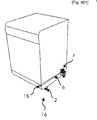
- Figure 1 is a perspective view of a household appliance.
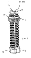
- Figure 2 is a perspective view of a height adjusting mechanism.
- Figure 3 is an exploded view of a height adjusting mechanism.
- Figure 4 is a top perspective view of the top position of the ring gear wherein a foot, which comprises a moving ring gear and to which a foot stopper ramp is attached.
- Figure 5 is a side perspective view of the position of the ring gear on the foot gear wherein a foot which comprises a moving ring gear and to which a foot stopper ramp is attached.
- Figure 6 is a bottom perspective view of the top position of the ring gear wherein a foot, which comprises a moving ring gear and to which a foot stopper ramp is attached.
- the household appliance (16) preferably a built-in household appliance which is the subject of the invention comprises a button (15) providing the adjustment of height, a height adjusting mechanism (7) providing the adjustment of the foot heights preferably the rear foot heights from the front part and an extension shaft (6) transferring the command from the button (15) to the height adjusting mechanism.
- Height adjusting mechanism (7) comprises a body (1) protecting itself and its parts, a foot (2) which carries and levels the household appliance (16), an worm gear (4) attached to the extension shaft (6) which moves the foot (2), a ring gear (5) which transfers the level the user uses as worm gear (4) to the foot (2), a foot stopper (3) on the foot (2) which prevents the elevation of the household appliance (16) over than the highest possible level without preventing its being lowered.
- the body (1) comprises a foot housing (8) into which the foot (2) is mounted on the body (1), more than one body gear tooth (10) inside the foot housing (8) and a worm gear housing (17) where the worm gear (4) is bedded.
- the foot (2) comprises more than one foot gear tooth (11) which is activated by moving among the body gear teeth (10), one or more cam housing (12) on the foot gear tooth (11), a fixing surface (9) for being fixed onto the floor below and a stopper housing (18) in which the foot stopper (3) is placed.
- the extension shaft (6) comprises one or more worm gear fixation housings (23) for being fixed to the height adjusting mechanism (7) to transfer the motion current on the extension shaft (6).
- the worm gear (4) comprises more than one gear pitch (27) for moving the foot (2) in the same number with the rotation amount when it is rotated around its own axis by the extension shaft (6), one bearing support (24) on both sides of the gear pitches for moving above, one or more worm gear fixation snap (22) close to the extension shaft (6) from the bearing supports (24) for attaching with the extension shaft (6) passing through the worm gear fixation housing (23) and one or more fixation ring (21) for preventing the removal of the worm gear fixation snap (22).
- Ring gear (5) comprises more than one ring gear (25) for transferring the drive force from the worm gear (4) to the foot (2), one or more cam (13) for moving on the foot gear tooth (11) sliding in the cam housing (12) and a support extension (26) for fixing into the foot housing (8).
- the body (1) comprises an assembly housing (28) for easy pass of the cam (13) on the top front surface of the foot housing (8) and easy mounting of the ring gear (5) and one or more holders (29) for holding the ring gear (5) on the foot housing (8) following the assembly.
- the foot stopper (3) comprises more than one foot stopper ramp (14) for preventing the excessive elevation of the foot (2) and returning to the prior gear pitch and one or more stopper fixation claw (19) for fixing into the stopper housing (18).
- the foot (2) comprises one or more stopper fixation housing (20) for providing its pass and fixation into the fixation claw (19).
- height adjusting mechanism (7) is grouped and fixed to the household appliance (16).
- the ring gear (5) is firstly fixed on the foot housing (8) in the mechanism body (1) in a way to be placed under the holder (29) and the cams (13) in the ring gear (5) are attached by rotating in a way to pass through the cam housing (12).
- the foot stopper (3) is fixed to the foot (2) and after the worm gear (4) is fixed on the worm gear housing (17) in the body (1), the extension shaft (6) is attached to the worm gear (4).
- the cams (13) rotate the foot (2) around its own axis by standing on the foot gear tooth (11) in the cam housing (12).
- the cams (13) move together with the ring gear (5) in the cam housings (12).
- At least one height adjusting mechanism (7) when all of the feet (2) of the household appliance (16) are wanted to be moved independent from each other, at least one height adjusting mechanism (7), at least one button (15) and at least one extension shaft (6) connecting the button (15) with the height adjusting mechanism (7) are used for each foot (2).
- the height adjusting mechanism (7) where there are feet wanted to be moved together is controlled by the same button (15) and the same extension shaft (6).
- the height adjusting mechanisms (7) where there are feet wanted to be moved together are controlled by the same button (7) and the same extension shaft (6).
- extension shaft (6) and the worm gear (4) are made as one piece and the drive force received from the button is transferred to the foot (2) by means of the ring gear (5).
- the user can elevate the feet (2) of the household appliance (16) without removing the foot (2) from the body and fix it at the desired position.
Landscapes
- Engineering & Computer Science (AREA)
- Textile Engineering (AREA)
- Finger-Pressure Massage (AREA)
- Ladders (AREA)
- Filters For Electric Vacuum Cleaners (AREA)
Abstract
Description
- This invention relates to a household appliance comprising a height adjusting mechanism adjusting the foot heights preferably the rear foot heights from the front part that is easily attained.
- In state of art, the position of the household appliance is adjusted with respect to the floor by having the screwed feet carrying the household appliances moved upwards and downwards by the user. It may be difficult or often impossible especially for the feet at the back part to be moved. Thus the back feet are moved by controlling from the front part.
- In known applications,
German Patent 19606460 discloses a height adjusting device for household appliance, which moves in the body and is locked by its form. - In another application in state of art,
European Patent Application 1103206 defines a height adjusting mechanism, which provides the required position by a roller. -
French Patent Application 2618208 -
German Utility Model 9421684U defines a household appliance having foots which can be elevated by screws. -
United States Patent 1417639 discloses a mechanism, which elevates by worm gears.DE 74 35 483 U describes a household appliance with a height adjusting mechanism according to the preamble ofclaim 1. - The object of this invention is to provide a household appliance comprising a height adjusting mechanism, which levels the foot at unreachable points by preventing the excess of the limit heights.
- The household appliance realized in order to attain above-mentioned objects of the present invention has been illustrated in the attached drawings, wherein;
- Figure 1 is a perspective view of a household appliance.
- Figure 2 is a perspective view of a height adjusting mechanism.
- Figure 3 is an exploded view of a height adjusting mechanism.
- Figure 4 is a top perspective view of the top position of the ring gear wherein a foot, which comprises a moving ring gear and to which a foot stopper ramp is attached.
- Figure 5 is a side perspective view of the position of the ring gear on the foot gear wherein a foot which comprises a moving ring gear and to which a foot stopper ramp is attached.
- Figure 6 is a bottom perspective view of the top position of the ring gear wherein a foot, which comprises a moving ring gear and to which a foot stopper ramp is attached.
- The components shown in the figures have been enumerated as below:
- 1.
- Body
- 2.
- Foot
- 3.
- Foot stopper
- 4.
- Worm gear
- 5.
- Ring gear
- 6.
- Extension shaft
- 7.
- Height adjusting mechanism
- 8.
- Foot housing
- 9.
- Fixing surface
- 10.
- Body gear teeth
- 11.
- Foot gear teeth
- 12.
- Cam housing
- 13.
- Cam
- 14.
- Foot stopper ramp
- 15.
- Button
- 16.
- Household appliance
- 17.
- Worm gear housing
- 18.
- Stopper housing
- 19.
- Stopper fixation claw
- 20.
- Stopper fixation housing
- 21.
- Fixation ring
- 22.
- Worm gear fixation snap
- 23.
- Worm gear fixation housing
- 24.
- Bearing support
- 25.
- Ring gear
- 26.
- Support Extension
- 27.
- Gear pitch
- 28.
- Assembly housing
- 29.
- Holder
- The household appliance (16) preferably a built-in household appliance which is the subject of the invention comprises a button (15) providing the adjustment of height, a height adjusting mechanism (7) providing the adjustment of the foot heights preferably the rear foot heights from the front part and an extension shaft (6) transferring the command from the button (15) to the height adjusting mechanism.
- Height adjusting mechanism (7) comprises a body (1) protecting itself and its parts, a foot (2) which carries and levels the household appliance (16), an worm gear (4) attached to the extension shaft (6) which moves the foot (2), a ring gear (5) which transfers the level the user uses as worm gear (4) to the foot (2), a foot stopper (3) on the foot (2) which prevents the elevation of the household appliance (16) over than the highest possible level without preventing its being lowered.
- The body (1) comprises a foot housing (8) into which the foot (2) is mounted on the body (1), more than one body gear tooth (10) inside the foot housing (8) and a worm gear housing (17) where the worm gear (4) is bedded.
- The foot (2) comprises more than one foot gear tooth (11) which is activated by moving among the body gear teeth (10), one or more cam housing (12) on the foot gear tooth (11), a fixing surface (9) for being fixed onto the floor below and a stopper housing (18) in which the foot stopper (3) is placed.
- The extension shaft (6) comprises one or more worm gear fixation housings (23) for being fixed to the height adjusting mechanism (7) to transfer the motion current on the extension shaft (6).
- The worm gear (4) comprises more than one gear pitch (27) for moving the foot (2) in the same number with the rotation amount when it is rotated around its own axis by the extension shaft (6), one bearing support (24) on both sides of the gear pitches for moving above, one or more worm gear fixation snap (22) close to the extension shaft (6) from the bearing supports (24) for attaching with the extension shaft (6) passing through the worm gear fixation housing (23) and one or more fixation ring (21) for preventing the removal of the worm gear fixation snap (22).
- Ring gear (5) comprises more than one ring gear (25) for transferring the drive force from the worm gear (4) to the foot (2), one or more cam (13) for moving on the foot gear tooth (11) sliding in the cam housing (12) and a support extension (26) for fixing into the foot housing (8).
- The body (1) comprises an assembly housing (28) for easy pass of the cam (13) on the top front surface of the foot housing (8) and easy mounting of the ring gear (5) and one or more holders (29) for holding the ring gear (5) on the foot housing (8) following the assembly.
- The foot stopper (3) comprises more than one foot stopper ramp (14) for preventing the excessive elevation of the foot (2) and returning to the prior gear pitch and one or more stopper fixation claw (19) for fixing into the stopper housing (18).
- The foot (2) comprises one or more stopper fixation housing (20) for providing its pass and fixation into the fixation claw (19).
- In a preferred embodiment of the invention, height adjusting mechanism (7) is grouped and fixed to the household appliance (16). When the height adjusting mechanism (7) is being grouped, the ring gear (5) is firstly fixed on the foot housing (8) in the mechanism body (1) in a way to be placed under the holder (29) and the cams (13) in the ring gear (5) are attached by rotating in a way to pass through the cam housing (12). After the foot (2) is attached to the body (1) of the mechanism, the foot stopper (3) is fixed to the foot (2) and after the worm gear (4) is fixed on the worm gear housing (17) in the body (1), the extension shaft (6) is attached to the worm gear (4).
- When the said extension shaft (6) and the worm gear (4) are rotated, it rotates the ring gear (5) and the cams (13) on the ring gear (5) rotate the foot (2) by standing on the walls of the cam housings (12) and foot gear tooth (11) moves the foot (2) in upwards and downwards direction by rotating between the body gear tooth (10) of the mechanism.
- Due to the foot gear tooth (11) on the foot (2) designed to pass through the gear tooth (10) in the body (1), the foot (2) and the body (1) acts as a screw and a "fixed nut" respectively. As the cam (13) slides inside the cam housing (12), there is no force applied in the vertical direction but only a rotational force is applied. When the ring gear (5) rotates, gear inside rotates on the foot (2) and pulls the foot (2) upwards.
- When the foot stopper (3) is elevated on the body (1), it prevents the leaving of the foot (2) from the body (1) at the limit height. When the ring gear (5) is rotated in the clockwise direction, the cams (13) rotate the foot (2) around its own axis by standing on the foot gear tooth (11) in the cam housing (12). As the foot gear tooth (11) moves in the body gear tooth (10) fixed to the body (1), it elevates the body (1) and the household appliance (16) connected to the body (1) towards the upper part of the foot (2). While the ring gear (5) moves dependent with the body (1) towards the upper parts of the foot (2), the cams (13) move together with the ring gear (5) in the cam housings (12). When the cams (13) reach to the foot stopper (3) at the peak of the foot (2), the cams (13) exceed the foot stopper ramps (14) and enter into the cam housing (12) in which the other cam moves by making the foot stopper ramp (14) flexible when it reaches at the peak point. Similarly when it is continued to be rotated, the cams go on top of the foot stopper ramp (14) and back to its cam housing (12) by making the foot stopper ramp (14) flexible. Therefore both the leaving of the body (1) from the foot (2) is prevented and no matter it is continued to be rotated, ring gear (5) can not rotate the foot (2) around its axis and the elevation of the body (1) in other words of the household appliance (16) is stopped.
- When the ring gear (5) is rotated in the anti-clockwise direction at the last position, the foot stopper ramp (14) lean against the side walls and starts to rotate foot stopper ramp (14) together with the foot (2) it is fixed. In this way, ring gear (5) returns to its lower gear pitch and allows the foot (2) gets into the ring gear (5). When the foot (2) starts to rotate, it lowers the body (1) and the household appliance (16) to which the body (1) is fixed towards the lower part of the foot (2) due to the body gear tooth (10) including the foot gear tooth (11). Meanwhile the cams (13) move towards the lower part of the foot (2) in the cam housings (12) and rotate the foot (2) at the same time. The lowering process of the body (1) and the household appliance (16) to which the body is fixed continues up to the point where the body gear teeth (10) lean against the fixing surface (9) and ring gear (5) can not be rotated by the worm gear (4).
- In an embodiment of the invention, when all of the feet (2) of the household appliance (16) are wanted to be moved independent from each other, at least one height adjusting mechanism (7), at least one button (15) and at least one extension shaft (6) connecting the button (15) with the height adjusting mechanism (7) are used for each foot (2).
- In another embodiment of the invention, when couple feet (2) of the household appliance (16) are wanted to be moved dependent to each other, the height adjusting mechanism (7) where there are feet wanted to be moved together is controlled by the same button (15) and the same extension shaft (6).
- In another embodiment of the invention, when all of the feet (2) of the household appliance (16) is wanted to be moved dependent to each other, the height adjusting mechanisms (7) where there are feet wanted to be moved together are controlled by the same button (7) and the same extension shaft (6).
- In another embodiment of the invention, the extension shaft (6) and the worm gear (4) are made as one piece and the drive force received from the button is transferred to the foot (2) by means of the ring gear (5).
- Thanks to the application, which is the subject of the invention, the user can elevate the feet (2) of the household appliance (16) without removing the foot (2) from the body and fix it at the desired position.
Claims (11)
- A household appliance (16) comprising a button (15) providing the height adjustment, feet (2) for holding itself, a height adjusting mechanism (7) adjusting the foot (2) heights preferably the rear foot heights from the front part and an extension shaft (6) transferring the commands from the button (15) to the height adjusting mechanism (7) and with a foot stopper (3) which prevents the elevation of the household appliance (16) over than the highest possible level, further characterized in that the foot stopper (3) prevents the elevation of the household appliance (16) over the highest possible level without obstructing foot level adjustment, and leaving from the height adjusting mechanism (7).
- A household appliance (16) as defined in Claim I characterized with a height adjusting mechanism (7) comprising a body (1) carrying and protecting itself and its parts together, an worm gear (4) elevating the foot (2) attached to the activated extension shaft (6) and a ring gear (5) transferring the level adjustment applied by the user as the gear of the worm gear (4) to the foot (2).
- A household appliance (16) as defined in Claim 1 and 2 characterized with a foot stopper (3) comprising more than one foot gear tooth (11) and foot (2) having one or more cam housing (12), a ring gear (5) having one or more cams (13) for allowing the foot (2) move on the foot gear teeth (11) by sliding in the cam housings (12) and one or more foot stopper ramp (14) for preventing the excessive elevation of the foot (2) and returning to the prior gear pitch.
- A household appliance (16) as defined in Claim 1 to 3 characterized by a body (1) comprising a foot housing (8) in which the foot (2) is mounted, one or more ring gear tooth (10) in the foot housing (8) and an worm gear housing (17) in which the worm gear (4) is embedded.
- A household appliance (16) as defined in Claim 1 to 4 characterized by a foot (2) comprising a fixing surface (9) for being fixed onto the floor below and a stopper housing (18) in which the foot stopper (3) is placed.
- A household appliance (16) as defined in Claim 1 to 5 characterized by an extension shaft (6) comprising one or more worm gear fixation housings (23) for being fixed to the height adjusting mechanism (7) to transfer the motion current on the extension shaft (6).
- A household appliance (16) as defined in Claim 1 to 6 characterized by an worm gear (4) comprising more than one gear pitch (27) for moving the foot (2) in the same number with the rotation amount when it is rotated around its own axis by the extension shaft (6), one bearing support (24) on both sides of the gear pitches for moving above, one or more worm gear fixation snap (22) close to the extension shaft (6) from the bearing supports (24) for attaching with the extension shaft (6) passing through the worm gear fixation housing (23) and one or more fixation ring (21) for preventing the removal of the worm gear fixation snap (22).
- A household appliance (16) as defined in Claim 1 to 7 characterized by ring gear (5) comprising more than one ring gear (25) for transferring the drive force from the worm gear (4) to the foot (2), one or more cam (13) for moving on the foot gear tooth (11) sliding in the cam housing (12) and a support extension (26) for fixing into the foot housing (8).
- A household appliance (16) as defined in Claim 1 to 7 characterized with a body (1) comprising an assembly housing (28) for easy pass of the cam (13) and easy mounting of the ring gear (5) on the top front surface of the foot housing (8).
- A household appliance (16) as defined in Claim 1 to 7 characterized by a foot stopper (3) comprising one or more stopper fixation claws (19) for being fixed into the stopper housing (18).
- A household appliance (16) as defined in Claim 1 to 7 characterized by a foot (2) comprising one or more stopper fixation housing (20) for being fixed into the fixation claw (19).
Applications Claiming Priority (2)
| Application Number | Priority Date | Filing Date | Title |
|---|---|---|---|
| TR200300816 | 2003-06-04 | ||
| PCT/IB2004/050837 WO2004107914A1 (en) | 2003-06-04 | 2004-06-03 | A household appliance |
Publications (2)
| Publication Number | Publication Date |
|---|---|
| EP1633218A1 EP1633218A1 (en) | 2006-03-15 |
| EP1633218B1 true EP1633218B1 (en) | 2007-08-15 |
Family
ID=33509776
Family Applications (1)
| Application Number | Title | Priority Date | Filing Date |
|---|---|---|---|
| EP04735952A Expired - Lifetime EP1633218B1 (en) | 2003-06-04 | 2004-06-03 | A household appliance |
Country Status (5)
| Country | Link |
|---|---|
| EP (1) | EP1633218B1 (en) |
| AT (1) | ATE369768T1 (en) |
| DE (1) | DE602004008268T2 (en) |
| TR (1) | TR200600446T1 (en) |
| WO (1) | WO2004107914A1 (en) |
Cited By (2)
| Publication number | Priority date | Publication date | Assignee | Title |
|---|---|---|---|---|
| US10376129B2 (en) | 2016-11-08 | 2019-08-13 | Whirlpool Corporation | Dishwasher leveling assembly |
| US10918259B2 (en) | 2019-01-10 | 2021-02-16 | Haier Us Appliance Solutions, Inc. | Dishwasher appliance with a leak pan |
Families Citing this family (23)
| Publication number | Priority date | Publication date | Assignee | Title |
|---|---|---|---|---|
| DE102004050362A1 (en) * | 2004-10-15 | 2006-04-27 | BSH Bosch und Siemens Hausgeräte GmbH | Adjusting device, in particular for a leveling foot of a household appliance |
| DE102007057511B3 (en) * | 2007-11-29 | 2009-07-16 | BSH Bosch und Siemens Hausgeräte GmbH | Household appliance with a height adjustment device for a device foot |
| DE102007057512A1 (en) * | 2007-11-29 | 2009-06-04 | BSH Bosch und Siemens Hausgeräte GmbH | household appliance |
| EP2326232B1 (en) | 2008-08-18 | 2016-08-10 | Arçelik Anonim Sirketi | A household appliance |
| WO2011109687A2 (en) | 2010-03-05 | 2011-09-09 | Cornell University | Bidirectional gear, method, and applications |
| DE102010055986A1 (en) * | 2010-10-28 | 2012-05-03 | Liebherr-Hausgeräte Ochsenhausen GmbH | Installation household appliance assembly e.g. refrigerator and/or freezer assembly, has actuating element that moves compensating elements from position in which elements do not fill gap into another position in which elements fill gap |
| TR201101953A2 (en) * | 2011-02-28 | 2012-04-24 | Bsh Ev Aletleri̇ San Ve Ti̇c A.Ş. | A built-in household appliance |
| US9572429B2 (en) | 2013-05-03 | 2017-02-21 | Arcelik Anonim Sirketi | Household appliance having improved height profile adjustable feet |
| KR102137945B1 (en) * | 2013-11-01 | 2020-07-27 | 삼성전자주식회사 | Washing machine |
| US10006582B2 (en) | 2014-11-03 | 2018-06-26 | Arcelik Anonim Sirketi | Household appliance with control height adjustment mechanism |
| ITUB20153365A1 (en) * | 2015-09-03 | 2017-03-03 | Scilm Spa | EQUIPMENT FOR THE ADJUSTMENT OF SUPPORTING FEET FOR FURNITURE UPON A SUPPORT TABLE AND FURNITURE SUPPORT FOR FURNITURE UPON A SUPPORT PLAN |
| CN106988082B (en) * | 2016-01-20 | 2020-12-18 | 青岛海尔滚筒洗衣机有限公司 | Automatic leveling device for washing machine, washing machine and leveling method |
| US9803730B1 (en) * | 2016-11-21 | 2017-10-31 | Bsh Hausgeraete Gmbh | Home appliance device |
| CN108278449B (en) | 2017-01-06 | 2021-01-26 | 青岛海尔洗衣机有限公司 | Footing for household appliance and household appliance |
| CN108626531B (en) | 2017-03-23 | 2021-09-07 | 青岛胶南海尔洗衣机有限公司 | Foot for household appliance and household appliance |
| CN108118497B (en) * | 2018-01-04 | 2020-05-19 | 无锡小天鹅电器有限公司 | Adjusting structure and washing machine |
| DE102018221159A1 (en) | 2018-12-06 | 2020-06-10 | BSH Hausgeräte GmbH | Home appliance |
| WO2020126470A1 (en) * | 2018-12-21 | 2020-06-25 | Arcelik Anonim Sirketi | A household appliance having reinforced and height adjustable feet mechanism |
| DE102020102242B3 (en) * | 2020-01-30 | 2020-12-31 | EDM-System GmbH | Support leg |
| TWI754296B (en) * | 2020-06-09 | 2022-02-01 | 新加坡商鴻運科股份有限公司 | Supporting footstand and cabinet |
| CN113865223B (en) * | 2020-06-30 | 2023-02-17 | 青岛海尔电冰箱有限公司 | Foot adjustment system and refrigerator having the same |
| US11723463B2 (en) | 2021-09-21 | 2023-08-15 | True Manufacturing Co., Inc. | Refrigerator cabinet |
| WO2022066727A1 (en) * | 2020-09-24 | 2022-03-31 | True Manufacturing Company, Inc. | Refrigerator cabinet |
Family Cites Families (5)
| Publication number | Priority date | Publication date | Assignee | Title |
|---|---|---|---|---|
| US1417639A (en) | 1921-03-19 | 1922-05-30 | Daniel L Sterner | Table leveler |
| DE7435483U (en) * | 1974-10-21 | 1976-06-10 | Bosch-Siemens Hausgeraete Gmbh, 7000 Stuttgart | ARRANGEMENT OF HEIGHT-ADJUSTABLE FEET ON HOUSEHOLD APPLIANCES, IN PARTICULAR FOR BUILT-IN KITCHENS, SUCH AS COOKERS, REFRIGERATORS, WASHING, DISHWASHER AND DRYING APPLIANCES, ETC. |
| DE4138112A1 (en) * | 1991-11-19 | 1993-05-27 | Bosch Siemens Hausgeraete | Cabinet-type household appliance features base elevation - joined to appliance bottom by means of screw, elevation rests on appliance bottom |
| DE9421684U1 (en) | 1993-04-30 | 1996-08-14 | Hermann Forster Ag, Arbon | Built-in household appliance with leveling elements |
| DE19606460B4 (en) | 1996-02-21 | 2012-09-27 | BSH Bosch und Siemens Hausgeräte GmbH | Household appliance with a height adjustment device for a leveling foot of the household appliance |
-
2004
- 2004-06-03 TR TR2006/00446T patent/TR200600446T1/en unknown
- 2004-06-03 WO PCT/IB2004/050837 patent/WO2004107914A1/en not_active Ceased
- 2004-06-03 EP EP04735952A patent/EP1633218B1/en not_active Expired - Lifetime
- 2004-06-03 DE DE602004008268T patent/DE602004008268T2/en not_active Expired - Lifetime
- 2004-06-03 AT AT04735952T patent/ATE369768T1/en not_active IP Right Cessation
Cited By (2)
| Publication number | Priority date | Publication date | Assignee | Title |
|---|---|---|---|---|
| US10376129B2 (en) | 2016-11-08 | 2019-08-13 | Whirlpool Corporation | Dishwasher leveling assembly |
| US10918259B2 (en) | 2019-01-10 | 2021-02-16 | Haier Us Appliance Solutions, Inc. | Dishwasher appliance with a leak pan |
Also Published As
| Publication number | Publication date |
|---|---|
| ATE369768T1 (en) | 2007-09-15 |
| WO2004107914A1 (en) | 2004-12-16 |
| DE602004008268T2 (en) | 2008-03-13 |
| DE602004008268D1 (en) | 2007-09-27 |
| TR200600446T1 (en) | 2006-08-21 |
| EP1633218A1 (en) | 2006-03-15 |
Similar Documents
| Publication | Publication Date | Title |
|---|---|---|
| EP1633218A1 (en) | A household appliance | |
| EP3055603B1 (en) | Cabinet levelling apparatus | |
| US20060060015A1 (en) | Gearing mechanism and vehicle seat with such a gearing mechanism | |
| EP2326232B1 (en) | A household appliance | |
| EP1522297A3 (en) | Extendable and retractable leg rest | |
| CN212490260U (en) | Supporting device and interventional medical system | |
| WO2000044096A2 (en) | Electric circuit control apparatus for pressure-controlled electric pressure cooker | |
| ES2932528T3 (en) | Sanitary ware arrangement with height adjustment | |
| KR20090072786A (en) | Height adjustment device on the bench | |
| CN208545799U (en) | Movable stand and elevating lever | |
| KR200244624Y1 (en) | Adjust The Height And The Angle Of TV Support | |
| KR960003459Y1 (en) | Tilt angle adjuster for vehicle's outside back mirror | |
| KR102549498B1 (en) | Arm rest for seat | |
| KR100864051B1 (en) | General purpose milling machine | |
| KR20070085615A (en) | Toilet seat raising and lowering device | |
| CN217477439U (en) | Bicycle rack | |
| CN115054476B (en) | Vertical dental unit | |
| CN110101471B (en) | Bite-level adjustable implant device and control method for making implant holes | |
| CN220354858U (en) | Foot components for home appliances and home appliances | |
| KR200400579Y1 (en) | Remote control of High & Low Control system & Improvement of the Ground & the Floor protection system | |
| KR200324307Y1 (en) | an elevator | |
| DK1054126T3 (en) | Running shoes for a parallel slide and tilt bracket | |
| CN116138609B (en) | A rod bracket that is easy to disassemble | |
| CN218091876U (en) | Wallboard adjusting mechanism | |
| KR200163861Y1 (en) | The desk |
Legal Events
| Date | Code | Title | Description |
|---|---|---|---|
| PUAI | Public reference made under article 153(3) epc to a published international application that has entered the european phase |
Free format text: ORIGINAL CODE: 0009012 |
|
| 17P | Request for examination filed |
Effective date: 20060104 |
|
| AK | Designated contracting states |
Kind code of ref document: A1 Designated state(s): AT BE BG CH CY CZ DE DK EE ES FI FR GB GR HU IE IT LI LU MC NL PL PT RO SE SI SK TR |
|
| DAX | Request for extension of the european patent (deleted) | ||
| GRAP | Despatch of communication of intention to grant a patent |
Free format text: ORIGINAL CODE: EPIDOSNIGR1 |
|
| GRAS | Grant fee paid |
Free format text: ORIGINAL CODE: EPIDOSNIGR3 |
|
| GRAA | (expected) grant |
Free format text: ORIGINAL CODE: 0009210 |
|
| AK | Designated contracting states |
Kind code of ref document: B1 Designated state(s): AT BE BG CH CY CZ DE DK EE ES FI FR GB GR HU IE IT LI LU MC NL PL PT RO SE SI SK TR |
|
| REG | Reference to a national code |
Ref country code: GB Ref legal event code: FG4D |
|
| REG | Reference to a national code |
Ref country code: CH Ref legal event code: EP |
|
| REG | Reference to a national code |
Ref country code: IE Ref legal event code: FG4D |
|
| REF | Corresponds to: |
Ref document number: 602004008268 Country of ref document: DE Date of ref document: 20070927 Kind code of ref document: P |
|
| PG25 | Lapsed in a contracting state [announced via postgrant information from national office to epo] |
Ref country code: NL Free format text: LAPSE BECAUSE OF FAILURE TO SUBMIT A TRANSLATION OF THE DESCRIPTION OR TO PAY THE FEE WITHIN THE PRESCRIBED TIME-LIMIT Effective date: 20070815 Ref country code: FI Free format text: LAPSE BECAUSE OF FAILURE TO SUBMIT A TRANSLATION OF THE DESCRIPTION OR TO PAY THE FEE WITHIN THE PRESCRIBED TIME-LIMIT Effective date: 20070815 Ref country code: BG Free format text: LAPSE BECAUSE OF FAILURE TO SUBMIT A TRANSLATION OF THE DESCRIPTION OR TO PAY THE FEE WITHIN THE PRESCRIBED TIME-LIMIT Effective date: 20071115 Ref country code: ES Free format text: LAPSE BECAUSE OF FAILURE TO SUBMIT A TRANSLATION OF THE DESCRIPTION OR TO PAY THE FEE WITHIN THE PRESCRIBED TIME-LIMIT Effective date: 20071126 |
|
| NLV1 | Nl: lapsed or annulled due to failure to fulfill the requirements of art. 29p and 29m of the patents act | ||
| PG25 | Lapsed in a contracting state [announced via postgrant information from national office to epo] |
Ref country code: LI Free format text: LAPSE BECAUSE OF FAILURE TO SUBMIT A TRANSLATION OF THE DESCRIPTION OR TO PAY THE FEE WITHIN THE PRESCRIBED TIME-LIMIT Effective date: 20070815 Ref country code: PL Free format text: LAPSE BECAUSE OF FAILURE TO SUBMIT A TRANSLATION OF THE DESCRIPTION OR TO PAY THE FEE WITHIN THE PRESCRIBED TIME-LIMIT Effective date: 20070815 Ref country code: CH Free format text: LAPSE BECAUSE OF FAILURE TO SUBMIT A TRANSLATION OF THE DESCRIPTION OR TO PAY THE FEE WITHIN THE PRESCRIBED TIME-LIMIT Effective date: 20070815 Ref country code: AT Free format text: LAPSE BECAUSE OF FAILURE TO SUBMIT A TRANSLATION OF THE DESCRIPTION OR TO PAY THE FEE WITHIN THE PRESCRIBED TIME-LIMIT Effective date: 20070815 |
|
| REG | Reference to a national code |
Ref country code: CH Ref legal event code: PL |
|
| ET | Fr: translation filed | ||
| PG25 | Lapsed in a contracting state [announced via postgrant information from national office to epo] |
Ref country code: BE Free format text: LAPSE BECAUSE OF FAILURE TO SUBMIT A TRANSLATION OF THE DESCRIPTION OR TO PAY THE FEE WITHIN THE PRESCRIBED TIME-LIMIT Effective date: 20070815 |
|
| PG25 | Lapsed in a contracting state [announced via postgrant information from national office to epo] |
Ref country code: DK Free format text: LAPSE BECAUSE OF FAILURE TO SUBMIT A TRANSLATION OF THE DESCRIPTION OR TO PAY THE FEE WITHIN THE PRESCRIBED TIME-LIMIT Effective date: 20070815 Ref country code: GR Free format text: LAPSE BECAUSE OF FAILURE TO SUBMIT A TRANSLATION OF THE DESCRIPTION OR TO PAY THE FEE WITHIN THE PRESCRIBED TIME-LIMIT Effective date: 20071116 |
|
| PG25 | Lapsed in a contracting state [announced via postgrant information from national office to epo] |
Ref country code: SK Free format text: LAPSE BECAUSE OF FAILURE TO SUBMIT A TRANSLATION OF THE DESCRIPTION OR TO PAY THE FEE WITHIN THE PRESCRIBED TIME-LIMIT Effective date: 20070815 Ref country code: CZ Free format text: LAPSE BECAUSE OF FAILURE TO SUBMIT A TRANSLATION OF THE DESCRIPTION OR TO PAY THE FEE WITHIN THE PRESCRIBED TIME-LIMIT Effective date: 20070815 Ref country code: PT Free format text: LAPSE BECAUSE OF FAILURE TO SUBMIT A TRANSLATION OF THE DESCRIPTION OR TO PAY THE FEE WITHIN THE PRESCRIBED TIME-LIMIT Effective date: 20080115 |
|
| PLBE | No opposition filed within time limit |
Free format text: ORIGINAL CODE: 0009261 |
|
| STAA | Information on the status of an ep patent application or granted ep patent |
Free format text: STATUS: NO OPPOSITION FILED WITHIN TIME LIMIT |
|
| PG25 | Lapsed in a contracting state [announced via postgrant information from national office to epo] |
Ref country code: RO Free format text: LAPSE BECAUSE OF FAILURE TO SUBMIT A TRANSLATION OF THE DESCRIPTION OR TO PAY THE FEE WITHIN THE PRESCRIBED TIME-LIMIT Effective date: 20070815 Ref country code: SE Free format text: LAPSE BECAUSE OF FAILURE TO SUBMIT A TRANSLATION OF THE DESCRIPTION OR TO PAY THE FEE WITHIN THE PRESCRIBED TIME-LIMIT Effective date: 20071115 |
|
| 26N | No opposition filed |
Effective date: 20080516 |
|
| PG25 | Lapsed in a contracting state [announced via postgrant information from national office to epo] |
Ref country code: MC Free format text: LAPSE BECAUSE OF NON-PAYMENT OF DUE FEES Effective date: 20080630 |
|
| GBPC | Gb: european patent ceased through non-payment of renewal fee |
Effective date: 20080603 |
|
| PG25 | Lapsed in a contracting state [announced via postgrant information from national office to epo] |
Ref country code: EE Free format text: LAPSE BECAUSE OF FAILURE TO SUBMIT A TRANSLATION OF THE DESCRIPTION OR TO PAY THE FEE WITHIN THE PRESCRIBED TIME-LIMIT Effective date: 20070815 Ref country code: IE Free format text: LAPSE BECAUSE OF NON-PAYMENT OF DUE FEES Effective date: 20080603 |
|
| PG25 | Lapsed in a contracting state [announced via postgrant information from national office to epo] |
Ref country code: GB Free format text: LAPSE BECAUSE OF NON-PAYMENT OF DUE FEES Effective date: 20080603 Ref country code: SI Free format text: LAPSE BECAUSE OF FAILURE TO SUBMIT A TRANSLATION OF THE DESCRIPTION OR TO PAY THE FEE WITHIN THE PRESCRIBED TIME-LIMIT Effective date: 20070815 |
|
| PG25 | Lapsed in a contracting state [announced via postgrant information from national office to epo] |
Ref country code: CY Free format text: LAPSE BECAUSE OF FAILURE TO SUBMIT A TRANSLATION OF THE DESCRIPTION OR TO PAY THE FEE WITHIN THE PRESCRIBED TIME-LIMIT Effective date: 20070815 |
|
| PG25 | Lapsed in a contracting state [announced via postgrant information from national office to epo] |
Ref country code: HU Free format text: LAPSE BECAUSE OF FAILURE TO SUBMIT A TRANSLATION OF THE DESCRIPTION OR TO PAY THE FEE WITHIN THE PRESCRIBED TIME-LIMIT Effective date: 20080216 Ref country code: LU Free format text: LAPSE BECAUSE OF NON-PAYMENT OF DUE FEES Effective date: 20080603 |
|
| PG25 | Lapsed in a contracting state [announced via postgrant information from national office to epo] |
Ref country code: IT Free format text: LAPSE BECAUSE OF NON-PAYMENT OF DUE FEES Effective date: 20080630 |
|
| REG | Reference to a national code |
Ref country code: FR Ref legal event code: PLFP Year of fee payment: 13 |
|
| REG | Reference to a national code |
Ref country code: FR Ref legal event code: PLFP Year of fee payment: 14 |
|
| REG | Reference to a national code |
Ref country code: FR Ref legal event code: PLFP Year of fee payment: 15 |
|
| PGFP | Annual fee paid to national office [announced via postgrant information from national office to epo] |
Ref country code: DE Payment date: 20180625 Year of fee payment: 15 |
|
| REG | Reference to a national code |
Ref country code: DE Ref legal event code: R119 Ref document number: 602004008268 Country of ref document: DE |
|
| PG25 | Lapsed in a contracting state [announced via postgrant information from national office to epo] |
Ref country code: DE Free format text: LAPSE BECAUSE OF NON-PAYMENT OF DUE FEES Effective date: 20200101 |
|
| PG25 | Lapsed in a contracting state [announced via postgrant information from national office to epo] |
Ref country code: FR Free format text: LAPSE BECAUSE OF NON-PAYMENT OF DUE FEES Effective date: 20190630 |
|
| PGFP | Annual fee paid to national office [announced via postgrant information from national office to epo] |
Ref country code: TR Payment date: 20230524 Year of fee payment: 20 |