EP1633117A1 - Method of notifying of service area in a mobile terminal - Google Patents
Method of notifying of service area in a mobile terminal Download PDFInfo
- Publication number
- EP1633117A1 EP1633117A1 EP05018779A EP05018779A EP1633117A1 EP 1633117 A1 EP1633117 A1 EP 1633117A1 EP 05018779 A EP05018779 A EP 05018779A EP 05018779 A EP05018779 A EP 05018779A EP 1633117 A1 EP1633117 A1 EP 1633117A1
- Authority
- EP
- European Patent Office
- Prior art keywords
- service
- service area
- received signal
- signal strength
- current received
- Prior art date
- Legal status (The legal status is an assumption and is not a legal conclusion. Google has not performed a legal analysis and makes no representation as to the accuracy of the status listed.)
- Withdrawn
Links
Images

Classifications
-
- H—ELECTRICITY
- H04—ELECTRIC COMMUNICATION TECHNIQUE
- H04B—TRANSMISSION
- H04B1/00—Details of transmission systems, not covered by a single one of groups H04B3/00 - H04B13/00; Details of transmission systems not characterised by the medium used for transmission
- H04B1/38—Transceivers, i.e. devices in which transmitter and receiver form a structural unit and in which at least one part is used for functions of transmitting and receiving
- H04B1/40—Circuits
-
- H—ELECTRICITY
- H04—ELECTRIC COMMUNICATION TECHNIQUE
- H04W—WIRELESS COMMUNICATION NETWORKS
- H04W48/00—Access restriction; Network selection; Access point selection
- H04W48/16—Discovering, processing access restriction or access information
-
- H—ELECTRICITY
- H04—ELECTRIC COMMUNICATION TECHNIQUE
- H04B—TRANSMISSION
- H04B17/00—Monitoring; Testing
- H04B17/20—Monitoring; Testing of receivers
- H04B17/23—Indication means, e.g. displays, alarms, audible means
-
- H—ELECTRICITY
- H04—ELECTRIC COMMUNICATION TECHNIQUE
- H04B—TRANSMISSION
- H04B17/00—Monitoring; Testing
- H04B17/30—Monitoring; Testing of propagation channels
- H04B17/309—Measuring or estimating channel quality parameters
- H04B17/318—Received signal strength
- H04B17/328—Reference signal received power [RSRP]; Reference signal received quality [RSRQ]
Definitions
- the present invention relates generally to a service area notification method in a mobile terminal.
- the present invention relates to a method of notifying a mobile terminal user about which service area his mobile terminal is located in and what service types are available in the service area, through the mobile terminal.
- a mobile terminal refers to a device, such as a cellular phone, PDA (Personal Digital Assistant), PCS (Personal Communication Service) phone, IMT-2000 (International Mobile Telecommunication-2000) terminal, GSM (Global System for Mobile Communication) terminal, or W-LAN (Wireless-Local Areas Network) terminal, that provides a communications function for enabling users to converse while roaming or to exchange data.
- PDA Personal Digital Assistant
- PCS Personal Computer System
- IMT-2000 International Mobile Telecommunication-2000
- GSM Global System for Mobile Communication
- W-LAN Wireless-Local Areas Network
- the mobile terminal is increasingly considered a necessity, to be carried at all times by any number of worldwide users irrespective of gender and age.
- the trend of the mobile terminal is toward small size, slimness, lightweight, and multimedia functionality, while taking into account the portability of the device.
- MSs mobile stations, hereinafter referred to as MSs
- the entire service area is segmented into relatively small radio areas called cells wherein a number of services are provided in each of the cells.
- This mobile communication system is typically comprised of a plurality of base stations (hereinafter referred to as BSs) that cover the cells and MSs that communicate by establishing radio channels with the BSs.
- BSs base stations
- MSs that communicate by establishing radio channels with the BSs.
- BSs Major access schemes between the BSs and the MSs include FDMA (Frequency Division Multiple Access), TDMA (Time Division Multiple Access), and CDMA (Code Division Multiple Access).
- FDMA Frequency Division Multiple Access
- TDMA Time Division Multiple Access
- CDMA Code Division Multiple Access
- a BS transmits a channel signal by which an MS identifies the BS for access.
- the proliferation of such mobile terminals has led to the increase in various services that the BSs can provide to MSs.
- an MS can transmit/receive a radio signal only within a service area, and available services are distinguished for the MS according to received signal strength indications in the service area.
- the MS when the MS is out of the service area, it typically outputs an out-of-service area notification message (e.g. NOSVC) to a display. That is, when the user is out of the range of the service area while roaming and moves to a no-service area, the MS displays a predetermined message or turns on/off a predetermined icon to notify the user that he is out of the service area.
- NOSVC out-of-service area notification message
- An object of the present invention is to substantially solve at least the above problems and disadvantages, and to provide at least the advantages below. Accordingly, an object of the present invention is to provide a method of notifying a mobile terminal user about which service area his mobile terminal is located in and what service types are available in the service area, through the mobile terminal.
- a service area notification method in a mobile terminal.
- a currently received signal strength of the mobile terminal is detected, and a service area corresponding to the currently received signal strength is determined from among a plurality of service areas distinguished according to received signal strength.
- the user is then notified of the determined service area and service type available in the service area. It is preferred that information regarding the plurality of service areas distinguished according to received signal strength and service types available in the service areas are stored in the device for reference.
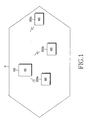
- FIG. 1 illustrates an exemplary configuration of a typical mobile communication system.
- a BS 100 and MSs 200a, 200b and 200c are shown located within a cell (that is, cell A), wherein MSs 200a, 200b and 200c are under the control of the BS 100.
- the BS 100 transmits a channel signal by which the MSs 200a, 200b and 200c can identify the BS 100 to be accessed.
- the MSs 200a, 200b and 200c establish radio channels and communicate with the BS 100 on the radio channels.
- the received signal strengths of the MSs 200a, 200b and 200c from the BS 100 are inversely proportion to their distances to the BS 100. However, if many MSs are in the vicinity of the BS 100 and thus, a cell density increases, the received signal strengths also decrease. Among the MSs 200a, 200b and 200c, the MS 200a nearest to the BS 100 has the highest received signal strength, while the MS 200c remotest from the BS 100 has the lowest received signal strength.
- FIG. 2 is a block diagram of an exemplary MS 200 provided with a camera according to an embodiment of the present invention.
- the MS 200 is comprised of a controller 210, a MODEM 220, an RF (Radio Frequency) module 223, an audio processor 225, a keypad 227, a memory 230, a camera module 240, an image processor 250, and a display 260.
- RF Radio Frequency
- the RF module 223 substantially controls the communications in the mobile terminal 200.
- the RF module 223 includes an RF transmitter (not shown) for upconverting and amplifying a transmission signal, and an RF receiver (not shown) for low-noise amplifying and downconverting a received signal.
- the RF module 223 can comprise an RF processor (not shown), an IF (Intermediate Frequency) processor (not shown), and a baseband processor (not shown).
- the MODEM 220 is provided with a transmitter (not shown) for encoding and modulating the transmission signal, and a receiver (not shown) for demodulating and decoding the received signal.
- the audio processor 225 may comprise a CODEC (not shown), which may include a data CODEC for processing packet data, and an audio CODEC for processing an audio signal including voice.
- CODEC not shown
- the audio processor 225 may comprise a CODEC (not shown), which may include a data CODEC for processing packet data, and an audio CODEC for processing an audio signal including voice.
- the audio processor 225 converts a digital audio signal received from the MODEM 220 into an analog signal through the audio CODEC prior to reproduction, or converts an analog audio signal generated from a microphone into a digital audio signal and transmits it to the MODEM 220.
- the CODEC may be provided separately or may be incorporated into the controller 210.
- the keypad 227 can be configured to have a key matrix structure (not shown).
- the keypad 227 includes alphanumerical keys, function keys, and a volume key located on the portable terminal, and can output a key input signal to the controller 210 corresponding to a key pressed by the user.
- the memory 230 may be configured to include a program memory and a data memory.
- the program memory stores programs for controlling the typical operations of the portable terminal 200.
- the program memory stores a program for notifying the user about which service area he is located in according to a received signal strength, and what service types are available in the service area.
- the data memory temporarily stores data generated during the execution of the programs.
- the memory 230 further stores a table of a plurality of service areas distinguished according to received signal strengths of the MS, and service types available in the service areas, as illustrated in Table 1 below.
- Table 1 Received signal strength Service area Available service type 1 st threshold (1Mbps or above) 1 st service area QoS-sensitive streaming service (moving pictures) and every data communication 2 nd threshold (384Kbps or above and below 1Mbps) 2 nd service area General data communication service (still image and wireless Internet) 3 rd threshold (below 384Kbps) 3 rd service area Voice call, message transmission/reception 0 No-service area Only functionalities of the terminal itself
- the area in which the MS is now located is the first service area and every radio data communication service including a QoS-sensitive streaming service (e.g. reception of moving pictures), is available to the MS while in the first service area.
- a QoS-sensitive streaming service e.g. reception of moving pictures
- the MS 200 is now located in the second service area which supports general data communication services including still image file transmission or wireless Internet, except for the QoS-sensitive streaming service.
- the MS 200 is now located in the third service area, and voice call and message transmission/reception are available to the MS while in the third service area. If the received signal strength is zero, all radio communication services are unavailable except for the functionality of the MS itself.
- Table 1 is a mere exemplary application and thus, the threshold ranges of column 1, service classifications of column 2, and available service types of column 3 are changeable in yet other embodiments of the present invention.
- controller 210 provides overall control for the MS 200, and may include the MODEM 220 and the CODEC.
- the controller 210 measures the strength of a signal received at an antenna of the MS 200, determines a current service area according to the received signal strength, determines service types available in the service area by referring to Table 1 stored in the memory 230, and displays the applicable service area and the service types on the display 260.
- the controller 210 can notify the user of the service area and the service types using a voice message, text message, alarm sound, color icon, or an avatar.
- the camera module 240 can be used in the exemplary embodiment of the present invention to capture an image. It includes a camera sensor (not shown) for converting the captured optical signal into an electrical signal, and a signal processor (not shown) for converting the analog image signal received from the camera sensor into digital data.
- the signal processor can be implemented as a DSP (Digital Signal Processor).
- the image processor 250 generates image data to display the image signal received from the camera module 240.
- the image processor 250 processes the image signal received from the camera module 240 on a frame basis, and outputs the frame image data according to the characteristics and size of the display 260.
- the image processor 250 is provided with an image CODEC (not shown) for compressing the frame image data to be displayed using a predetermined method, or decompressing the compressed frame image data into the original frame image data.
- the image CODEC can be one of a JPEG CODEC, an MPEG4 CODEC, and a Wavelet CODEC.
- the image processor 250 has an OSD (On Screen Display) function and outputs OSD data according to a screen size under the control of the controller 210.
- OSD On Screen Display
- the display 260 displays the image data received from the image processor 250 and user data received from the controller 210.
- the display 260 may use an LCD (Liquid Crystal Display) (not shown).
- the display 260 includes an LCD controller, a memory for storing image data, and an LCD device. If the LCD is implemented as a touch screen, the display 260 can further serve as an input portion.
- the display 260 under the control of the controller 210, notifies the user of a service area wherein the MS 200 is located, and what service types are available in the service area.
- the controller 210 senses the origination mode, processes received dialing information through the MODEM 220, and converts the processed information into an RF signal through the RF module 223 prior to transmission. Upon the generation of a response signal from another party, the controller 210 senses the response signal through the RF module 223 and the MODEM 220. A voice communication path is then established through the audio processor 225 so that the user can converse.
- the controller 210 senses the termination mode through the MODEM 220 and generates a ring signal through the audio processor 225.
- the controller 210 senses the answer and establishes the voice communication path through the audio processor 225 so that the user can converse.
- the controller 210 displays the text data processed by the MODEM 220 on the display 260.
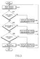
- FIG. 3 is a flowchart illustrating an exemplary method for notifying a user about a service area wherein the MS 200 is located, and what service types are available in the service area according to an embodiment of the present invention.
- a total of four illustrative service areas are defined according to received signal strength as illustrated in Table 1. That is, the method depicted in FIG. 3 is performed under the assumption that the received signal strength ranges for the first, second and third service areas, and the no-service area are respectively set as the first threshold range (e.g. 1Mbps or above), the second threshold range (e.g. 384kbps or above, but below 1Mbps), the third threshold range (e.g. below 384kbps, but above zero), and zero.
- the first threshold range e.g. 1Mbps or above
- the second threshold range e.g. 384kbps or above, but below 1Mbps
- the third threshold range e.g. below 384kbps, but above zero
- the present invention is not limited to the above specific values, categories or ranges, and thus it is to be appreciated that the thresholds are changeable in yet other embodiments of the present invention.
- the controller 210 first detects the strength of a signal received through the antenna of an MS 200 in step S310.
- step S320 the controller 210 compares the detected received signal strength with the threshold value ranges in the table stored in the memory 230 and determines whether the received signal strength falls within the first threshold range corresponding to the first service area wherein QoS-sensitive streaming service is available.
- the controller 210 notifies the user of the first service area and the service types available in the first service area through the display 260 in step S330. Specifically, for the notification step, the controller 210 may output a voice message or an alarm sound through the audio processor 225, or may display a text message, color icon, or an avatar on the display 260, or may output a combination of the voice and text messages at the same time.
- the QoS-sensitive streaming service such as reception of moving pictures, and any other radio data communication service are available to the MS 200 while in the first service area.
- the controller 210 determines whether it falls within the second threshold range for the second service area in step S340.
- the controller 210 notifies the user of the second service area supporting general data communication services through the display 260 or the audio processor, and notifies the user of the service types available in the second service area through the display 260 in step S350.
- the general data communication services include wireless Internet service, transmission/reception of still image files, voice call, and message transmission/reception, with the exception of the QoS-sensitive streaming service.
- step S340 determines whether it falls within the third threshold range for the third service area in step S360.
- the controller 210 notifies the user of the third service area supporting voice call and message transmission/reception through the display 260 or the audio processor, and notifies the user of the service types available in the third service area through the display 260 in step S370.
- the third service area only voice call and message transmission/reception are available.
- the controller 210 determines that the MS 200 is located in the no-service area where radio communication is impossible and notifies the user of the no-service area through the display 260 or the audio processor 225 in step S380. In the no-service area, no radio data communication is available. However, if the MS 200 is equipped with a camera, it can perform a multimedia function like photographing.
- the method of FIG. 3 has been described above given that the received signal strength becomes weak as the MS 200 is located farther from the BS 100 as illustrated and described in regard to FIG. 1, for example, as the MS 200 is moving farther from the BS 100.
- the received signal strength also becomes weak.
- the user of an MS is notified of service areas according to received signal strength and is further notified of the service types available in the service areas. Therefore, the user can easily determine the current service area and the service types available in the current service area.
Landscapes
- Engineering & Computer Science (AREA)
- Computer Networks & Wireless Communication (AREA)
- Signal Processing (AREA)
- Quality & Reliability (AREA)
- Physics & Mathematics (AREA)
- Electromagnetism (AREA)
- Computer Security & Cryptography (AREA)
- Mobile Radio Communication Systems (AREA)
- Telephone Function (AREA)
Abstract
Description
- This application claims the benefit under 35 U.S.C. §119(a) of Korean Patent Application No. 10-2004-0071256 entitled "Method Of Notifying Of Service Area In A Mobile Terminal" filed in the Korean Intellectual Property Office on September 7, 2004, the entire disclosure of which is incorporated herein by reference.
- The present invention relates generally to a service area notification method in a mobile terminal. In particular, the present invention relates to a method of notifying a mobile terminal user about which service area his mobile terminal is located in and what service types are available in the service area, through the mobile terminal.
- Typically, a mobile terminal refers to a device, such as a cellular phone, PDA (Personal Digital Assistant), PCS (Personal Communication Service) phone, IMT-2000 (International Mobile Telecommunication-2000) terminal, GSM (Global System for Mobile Communication) terminal, or W-LAN (Wireless-Local Areas Network) terminal, that provides a communications function for enabling users to converse while roaming or to exchange data.
- The mobile terminal is increasingly considered a necessity, to be carried at all times by any number of worldwide users irrespective of gender and age. The trend of the mobile terminal is toward small size, slimness, lightweight, and multimedia functionality, while taking into account the portability of the device. In the existing mobile communication system implemented with current mobile terminals (that is, mobile stations, hereinafter referred to as MSs), the entire service area is segmented into relatively small radio areas called cells wherein a number of services are provided in each of the cells.
- This mobile communication system is typically comprised of a plurality of base stations (hereinafter referred to as BSs) that cover the cells and MSs that communicate by establishing radio channels with the BSs.
- Major access schemes between the BSs and the MSs include FDMA (Frequency Division Multiple Access), TDMA (Time Division Multiple Access), and CDMA (Code Division Multiple Access). In any of the above access schemes, a BS transmits a channel signal by which an MS identifies the BS for access. The proliferation of such mobile terminals has led to the increase in various services that the BSs can provide to MSs.
- However, an MS can transmit/receive a radio signal only within a service area, and available services are distinguished for the MS according to received signal strength indications in the service area.
- Therefore, when the MS is out of the service area, it typically outputs an out-of-service area notification message (e.g. NOSVC) to a display. That is, when the user is out of the range of the service area while roaming and moves to a no-service area, the MS displays a predetermined message or turns on/off a predetermined icon to notify the user that he is out of the service area.
- However, it would also be beneficial for the user to be further informed of available service types according to the current received signal strength, rather than to be simply notified that he is out of a service area when he moves out of the service area.
- Accordingly, a need exists for a system and method for notifying a user of current service areas and of the service types available in the current service areas.
- An object of the present invention is to substantially solve at least the above problems and disadvantages, and to provide at least the advantages below. Accordingly, an object of the present invention is to provide a method of notifying a mobile terminal user about which service area his mobile terminal is located in and what service types are available in the service area, through the mobile terminal.
- The above and other objects are substantially achieved by providing a service area notification method in a mobile terminal. A currently received signal strength of the mobile terminal is detected, and a service area corresponding to the currently received signal strength is determined from among a plurality of service areas distinguished according to received signal strength. The user is then notified of the determined service area and service type available in the service area. It is preferred that information regarding the plurality of service areas distinguished according to received signal strength and service types available in the service areas are stored in the device for reference.
- The above and other objects, features and advantages of the present invention will become more apparent from the following detailed description when taken in conjunction with the accompanying drawings in which:
- FIG. 1 illustrates an example configuration of a conventional mobile communication system;
- FIG. 2 is a block diagram of an MS according to an embodiment of the present invention; and
- FIG. 3 is a flowchart illustrating an exemplary method for notifying a user about which service area the MS is located in and what service types are available in the service area, according to an embodiment of the present invention.
- Throughout the drawings, like reference numerals will be understood to refer to like parts, components and structures.
- An exemplary embodiment of the present invention will be described herein below with reference to the accompanying drawings. In the following description, functions or constructions that are well-known to those skilled in the art are not described in detail since they would obscure the invention in unnecessary detail.
- FIG. 1 illustrates an exemplary configuration of a typical mobile communication system. Referring to FIG. 1, a
BS 100 andMSs MSs BS 100. TheBS 100 transmits a channel signal by which the MSs 200a, 200b and 200c can identify theBS 100 to be accessed. The MSs 200a, 200b and 200c establish radio channels and communicate with theBS 100 on the radio channels. - The received signal strengths of the
MSs BS 100 are inversely proportion to their distances to theBS 100. However, if many MSs are in the vicinity of theBS 100 and thus, a cell density increases, the received signal strengths also decrease. Among the MSs 200a, 200b and 200c, the MS 200a nearest to the BS 100 has the highest received signal strength, while the MS 200c remotest from the BS 100 has the lowest received signal strength. - FIG. 2 is a block diagram of an
exemplary MS 200 provided with a camera according to an embodiment of the present invention. - Referring to FIG. 2, the MS 200 is comprised of a
controller 210, aMODEM 220, an RF (Radio Frequency)module 223, anaudio processor 225, akeypad 227, amemory 230, acamera module 240, animage processor 250, and adisplay 260. - The
RF module 223 substantially controls the communications in themobile terminal 200. TheRF module 223 includes an RF transmitter (not shown) for upconverting and amplifying a transmission signal, and an RF receiver (not shown) for low-noise amplifying and downconverting a received signal. In doing so, theRF module 223 can comprise an RF processor (not shown), an IF (Intermediate Frequency) processor (not shown), and a baseband processor (not shown). - The MODEM 220 is provided with a transmitter (not shown) for encoding and modulating the transmission signal, and a receiver (not shown) for demodulating and decoding the received signal.
- The
audio processor 225 may comprise a CODEC (not shown), which may include a data CODEC for processing packet data, and an audio CODEC for processing an audio signal including voice. - The
audio processor 225 converts a digital audio signal received from the MODEM 220 into an analog signal through the audio CODEC prior to reproduction, or converts an analog audio signal generated from a microphone into a digital audio signal and transmits it to theMODEM 220. The CODEC may be provided separately or may be incorporated into thecontroller 210. - The
keypad 227 can be configured to have a key matrix structure (not shown). Thekeypad 227 includes alphanumerical keys, function keys, and a volume key located on the portable terminal, and can output a key input signal to thecontroller 210 corresponding to a key pressed by the user. - The
memory 230 may be configured to include a program memory and a data memory. The program memory stores programs for controlling the typical operations of theportable terminal 200. According to an embodiment of the present invention, the program memory stores a program for notifying the user about which service area he is located in according to a received signal strength, and what service types are available in the service area. The data memory temporarily stores data generated during the execution of the programs. - The
memory 230 further stores a table of a plurality of service areas distinguished according to received signal strengths of the MS, and service types available in the service areas, as illustrated in Table 1 below.Table 1 Received signal strength Service area Available service type 1st threshold (1Mbps or above) 1st service area QoS-sensitive streaming service (moving pictures) and every data communication 2nd threshold (384Kbps or above and below 1Mbps) 2nd service area General data communication service (still image and wireless Internet) 3rd threshold (below 384Kbps) 3rd service area Voice call, message transmission/reception 0 No-service area Only functionalities of the terminal itself - Referring to Table 1, if the strength of a received signal at the
MS 200 is equal to or greater than the first threshold, the area in which the MS is now located is the first service area and every radio data communication service including a QoS-sensitive streaming service (e.g. reception of moving pictures), is available to the MS while in the first service area. - If the received signal strength falls within the second threshold range, the MS 200 is now located in the second service area which supports general data communication services including still image file transmission or wireless Internet, except for the QoS-sensitive streaming service.
- If the received signal strength falls within the third threshold range, the MS 200 is now located in the third service area, and voice call and message transmission/reception are available to the MS while in the third service area. If the received signal strength is zero, all radio communication services are unavailable except for the functionality of the MS itself.
- It is to be understood herein that Table 1 is a mere exemplary application and thus, the threshold ranges of
column 1, service classifications of column 2, and available service types of column 3 are changeable in yet other embodiments of the present invention. - Returning to FIG. 2, the
controller 210 provides overall control for the MS 200, and may include the MODEM 220 and the CODEC. - According to an embodiment of the present invention, the
controller 210 measures the strength of a signal received at an antenna of theMS 200, determines a current service area according to the received signal strength, determines service types available in the service area by referring to Table 1 stored in thememory 230, and displays the applicable service area and the service types on thedisplay 260. - The
controller 210 can notify the user of the service area and the service types using a voice message, text message, alarm sound, color icon, or an avatar. - The
camera module 240 can be used in the exemplary embodiment of the present invention to capture an image. It includes a camera sensor (not shown) for converting the captured optical signal into an electrical signal, and a signal processor (not shown) for converting the analog image signal received from the camera sensor into digital data. The signal processor can be implemented as a DSP (Digital Signal Processor). - The
image processor 250 generates image data to display the image signal received from thecamera module 240. - The
image processor 250 processes the image signal received from thecamera module 240 on a frame basis, and outputs the frame image data according to the characteristics and size of thedisplay 260. Theimage processor 250 is provided with an image CODEC (not shown) for compressing the frame image data to be displayed using a predetermined method, or decompressing the compressed frame image data into the original frame image data. - The image CODEC can be one of a JPEG CODEC, an MPEG4 CODEC, and a Wavelet CODEC. In the exemplary embodiment of the present invention, it can be assumed that the
image processor 250 has an OSD (On Screen Display) function and outputs OSD data according to a screen size under the control of thecontroller 210. - The
display 260 displays the image data received from theimage processor 250 and user data received from thecontroller 210. Thedisplay 260 may use an LCD (Liquid Crystal Display) (not shown). In this case, thedisplay 260 includes an LCD controller, a memory for storing image data, and an LCD device. If the LCD is implemented as a touch screen, thedisplay 260 can further serve as an input portion. - According to an embodiment of the present invention, under the control of the
controller 210, thedisplay 260 notifies the user of a service area wherein theMS 200 is located, and what service types are available in the service area. - In operation, when the user dials through the
keypad 227 and sets an origination mode, thecontroller 210 senses the origination mode, processes received dialing information through theMODEM 220, and converts the processed information into an RF signal through theRF module 223 prior to transmission. Upon the generation of a response signal from another party, thecontroller 210 senses the response signal through theRF module 223 and theMODEM 220. A voice communication path is then established through theaudio processor 225 so that the user can converse. - In a termination mode, the
controller 210 senses the termination mode through theMODEM 220 and generates a ring signal through theaudio processor 225. When the user answers, thecontroller 210 senses the answer and establishes the voice communication path through theaudio processor 225 so that the user can converse. - While the origination and termination modes have been described in relation to a voice call, they are applied in substantially the same manner for data communication, including packet data and image data. In an idle mode or in text communications, the
controller 210 displays the text data processed by theMODEM 220 on thedisplay 260. - An exemplary operation for notifying a user of a service area wherein the
MS 200 is located according to the received signal strength of the MS, and for further notifying a user of service types available in the service area, will now be described in greater detail with reference to FIG. 3. - FIG. 3 is a flowchart illustrating an exemplary method for notifying a user about a service area wherein the
MS 200 is located, and what service types are available in the service area according to an embodiment of the present invention. - In accordance with an exemplary embodiment of the present invention, a total of four illustrative service areas are defined according to received signal strength as illustrated in Table 1. That is, the method depicted in FIG. 3 is performed under the assumption that the received signal strength ranges for the first, second and third service areas, and the no-service area are respectively set as the first threshold range (e.g. 1Mbps or above), the second threshold range (e.g. 384kbps or above, but below 1Mbps), the third threshold range (e.g. below 384kbps, but above zero), and zero.
- The present invention is not limited to the above specific values, categories or ranges, and thus it is to be appreciated that the thresholds are changeable in yet other embodiments of the present invention.
- Referring to FIGS. 2 and 3, the
controller 210 first detects the strength of a signal received through the antenna of anMS 200 in step S310. - In step S320, the
controller 210 compares the detected received signal strength with the threshold value ranges in the table stored in thememory 230 and determines whether the received signal strength falls within the first threshold range corresponding to the first service area wherein QoS-sensitive streaming service is available. - If the received signal strength corresponds to the first threshold range for the first service area, the
controller 210 notifies the user of the first service area and the service types available in the first service area through thedisplay 260 in step S330. Specifically, for the notification step, thecontroller 210 may output a voice message or an alarm sound through theaudio processor 225, or may display a text message, color icon, or an avatar on thedisplay 260, or may output a combination of the voice and text messages at the same time. The QoS-sensitive streaming service such as reception of moving pictures, and any other radio data communication service are available to theMS 200 while in the first service area. - If the received signal strength does not fall within the first threshold range in step S320, the
controller 210 then determines whether it falls within the second threshold range for the second service area in step S340. - If the received signal strength corresponds to the second service area, the
controller 210 notifies the user of the second service area supporting general data communication services through thedisplay 260 or the audio processor, and notifies the user of the service types available in the second service area through thedisplay 260 in step S350. The general data communication services include wireless Internet service, transmission/reception of still image files, voice call, and message transmission/reception, with the exception of the QoS-sensitive streaming service. - If the received signal strength does not fall within the second threshold range in step S340, the
controller 210 then determines whether it falls within the third threshold range for the third service area in step S360. - If the received signal strength corresponds to the third service area, the
controller 210 notifies the user of the third service area supporting voice call and message transmission/reception through thedisplay 260 or the audio processor, and notifies the user of the service types available in the third service area through thedisplay 260 in step S370. In the third service area, only voice call and message transmission/reception are available. - If the received signal strength is too weak to support voice call and message transmission/reception (for example, zero strength) in step S360, the
controller 210 the determines that theMS 200 is located in the no-service area where radio communication is impossible and notifies the user of the no-service area through thedisplay 260 or theaudio processor 225 in step S380. In the no-service area, no radio data communication is available. However, if theMS 200 is equipped with a camera, it can perform a multimedia function like photographing. - Notably, the method of FIG. 3 has been described above given that the received signal strength becomes weak as the
MS 200 is located farther from theBS 100 as illustrated and described in regard to FIG. 1, for example, as theMS 200 is moving farther from theBS 100. However, even when in the vicinity of theBS 100, if manyother MSs 200 are located in the same area such that cell density is increased, the received signal strength also becomes weak. - In accordance with the present invention as described above, the user of an MS is notified of service areas according to received signal strength and is further notified of the service types available in the service areas. Therefore, the user can easily determine the current service area and the service types available in the current service area.
- While the invention has been shown and described with reference to certain exemplary embodiments thereof, it will be understood by those skilled in the art that various changes in form and details may be made therein without departing from the spirit and scope of the invention as defined by the appended claims.
Claims (9)
- A service area notification method in a mobile terminal, comprising the steps of:detecting a current received signal strength of the mobile terminal;determining a service area and service types corresponding to the current received signal strength from among a plurality of service areas, respective ones of said plurality of service areas being distinguished according to received signal strength and service types available; andnotifying a user of the determined service area and the service types available in the determined service area.
- The service area notification method of claim 1, further comprising the step of:storing the plurality of service areas distinguished according to received signal strength and service types available.
- The service area notification method of claim 1, wherein the step of determining the service types comprises the steps of:determining whether the current received signal strength falls within a first range corresponding to a first service area wherein at least QoS (Quality of Service)-sensitive streaming service is available;determining whether the current received signal strength falls within a second range corresponding to a second service area wherein at least general data communication services are available if the current received signal strength does not fall within the first range;determining whether the current received signal strength falls within a third range corresponding to a third service area wherein at least voice call and message transmission/reception are available if the current received signal strength does not fall within the second range; anddetermining that the mobile terminal is located in a no-service area wherein radio communication is substantially impossible if the current received strength does not fall within the third range.
- The service area notification method of claim 1, wherein the notification step comprises the step of:notifying the user about the service types available in the determined service area by providing at least one of a voice message, a text message, an alarm sound, a color icon, and an avatar.
- The service area notification method of claim 3, wherein the general data communication services comprise wireless Internet service, still image file transmission/reception, voice call, and message transmission/reception.
- A mobile terminal providing service area notification, comprising:a controller for detecting a current received signal strength of the mobile terminal and determining a service area and service types corresponding to the current received signal strength from among a plurality of service areas distinguished respectively according to received signal strength and service types available; anda display for notifying the user about the service types available in the determined service area by providing at least one of a text message, a color icon, and an avatar; andan audio processor for notifying the user about the service types available in the determined service area by providing at least one of a voice message and an alarm sound.
- The mobile terminal of claim 6, further comprising:a memory for storing the plurality of service areas distinguished according to received signal strength and service types available.
- The mobile terminal of claim 6, wherein the controller further comprises:a first component for determining whether the current received signal strength falls within a first range corresponding to a first service area wherein at least QoS (Quality of Service)-sensitive streaming service is available;a second component for determining whether the current received signal strength falls within a second range corresponding to a second service area wherein at least general data communication services are available if the current received signal strength does not fall within the first range;a third component for determining whether the current received signal strength falls within a third range corresponding to a third service area wherein at least voice call and message transmission/reception are available if the current received signal strength does not fall within the second range; anda fourth component for determining that the mobile terminal is located in a no-service area wherein radio communication is substantially impossible if the current received strength does not fall within the third range.
- The mobile terminal of claim 8, wherein the general data communication services comprise wireless Internet service, still image file transmission/reception, voice call, and message transmission/reception.
Applications Claiming Priority (1)
| Application Number | Priority Date | Filing Date | Title |
|---|---|---|---|
| KR1020040071256A KR100651464B1 (en) | 2004-09-07 | 2004-09-07 | Service area notification method of mobile terminal |
Publications (1)
| Publication Number | Publication Date |
|---|---|
| EP1633117A1 true EP1633117A1 (en) | 2006-03-08 |
Family
ID=36166875
Family Applications (1)
| Application Number | Title | Priority Date | Filing Date |
|---|---|---|---|
| EP05018779A Withdrawn EP1633117A1 (en) | 2004-09-07 | 2005-08-30 | Method of notifying of service area in a mobile terminal |
Country Status (4)
| Country | Link |
|---|---|
| US (1) | US7493114B2 (en) |
| EP (1) | EP1633117A1 (en) |
| KR (1) | KR100651464B1 (en) |
| CN (1) | CN100358384C (en) |
Cited By (1)
| Publication number | Priority date | Publication date | Assignee | Title |
|---|---|---|---|---|
| WO2023107728A1 (en) * | 2021-12-10 | 2023-06-15 | Viasat, Inc. | Systems and methods for in-flight connectivity |
Families Citing this family (19)
| Publication number | Priority date | Publication date | Assignee | Title |
|---|---|---|---|---|
| CN101094434B (en) * | 2006-06-19 | 2011-02-02 | 华为技术有限公司 | Method for subscribing service related notification in mobile broadcast system |
| US8737350B2 (en) * | 2007-03-21 | 2014-05-27 | Qualcomm Incorporated | Methods and apparatus for RF handoff in a multi-frequency network |
| US8948757B2 (en) * | 2007-03-21 | 2015-02-03 | Qualcomm Incorporated | Methods and apparatus for RF handoff in a multi-frequency network |
| US8750248B2 (en) * | 2007-03-21 | 2014-06-10 | Qualcomm Incorporated | Methods and apparatus for RF handoff in a multi-frequency network |
| US7853244B1 (en) | 2007-03-21 | 2010-12-14 | At&T Mobility Ii Llc | Exclusive wireless service proposals |
| US8737353B2 (en) * | 2007-03-21 | 2014-05-27 | Qualcomm Incorporated | Methods and apparatus for RF handoff in a multi-frequency network |
| US8565799B2 (en) * | 2007-04-04 | 2013-10-22 | Qualcomm Incorporated | Methods and apparatus for flow data acquisition in a multi-frequency network |
| US20080301556A1 (en) * | 2007-05-30 | 2008-12-04 | Motorola, Inc. | Method and apparatus for displaying operational information about an electronic device |
| US20080297515A1 (en) * | 2007-05-30 | 2008-12-04 | Motorola, Inc. | Method and apparatus for determining the appearance of a character display by an electronic device |
| KR20090029011A (en) * | 2007-09-17 | 2009-03-20 | 삼성전자주식회사 | Call tone setting function Move voice call terminal and call tone setting method |
| KR101397012B1 (en) * | 2007-11-20 | 2014-06-27 | 엘지전자 주식회사 | Terminal and method of setting service for data communication therein |
| EP2071355B1 (en) * | 2007-12-13 | 2015-07-29 | Swisscom AG | System and method for determining a location area of a mobile user |
| US8570939B2 (en) | 2008-03-07 | 2013-10-29 | Qualcomm Incorporated | Methods and systems for choosing cyclic delays in multiple antenna OFDM systems |
| JP2009225194A (en) * | 2008-03-17 | 2009-10-01 | Fujitsu Ltd | Mobile terminal unit, wireless unit, information processor, and program for preventing thing left behind |
| CN101924955A (en) | 2009-06-16 | 2010-12-22 | 中兴通讯股份有限公司 | A method and system for improving the broadcasting quality of mobile phone TV |
| CN103294165B (en) * | 2013-04-12 | 2016-08-10 | 苏州佳世达电通有限公司 | Running gear and driving method thereof |
| CN116133139B (en) * | 2022-12-29 | 2025-12-09 | 中国联合网络通信集团有限公司 | Service area determining method, device, equipment and storage medium |
| CN116471212B (en) * | 2023-04-17 | 2023-11-14 | 安芯网盾(北京)科技有限公司 | Service type-based network traffic data processing method and system |
| WO2025062420A1 (en) * | 2023-09-18 | 2025-03-27 | Jio Platforms Limited | Method and system for notifying users for consuming a new communication service |
Citations (6)
| Publication number | Priority date | Publication date | Assignee | Title |
|---|---|---|---|---|
| US4683459A (en) * | 1985-05-28 | 1987-07-28 | Adt, Inc. | Alarm system test annunciator |
| EP0310379A2 (en) * | 1987-09-29 | 1989-04-05 | Kabushiki Kaisha Toshiba | Radio telephone apparatus |
| EP1079540A2 (en) * | 1999-07-12 | 2001-02-28 | Nokia Mobile Phones Ltd. | Method and arrangement for service-based indication and control of service need |
| WO2002011475A1 (en) * | 2000-08-01 | 2002-02-07 | Tae Gyu Lee | Method and apparatus of intelligent icon interface |
| EP1220560A2 (en) * | 2000-12-29 | 2002-07-03 | Samsung Electronics Co., Ltd. | Operator selection method for a mobile station |
| US20040152419A1 (en) * | 2003-01-03 | 2004-08-05 | Samsung Electronics Co., Ltd. | Method for displaying reception sensitivity on a multi-functional mobile terminal |
Family Cites Families (13)
| Publication number | Priority date | Publication date | Assignee | Title |
|---|---|---|---|---|
| KR970055712A (en) * | 1995-12-02 | 1997-07-31 | 권혁조 | How to connect communication service system with dual mode terminal |
| KR100254193B1 (en) * | 1997-06-23 | 2000-04-15 | 윤종용 | Ct2 wireless telecommunication network capable of displaying a cell range and method for displaying cell area of wireless terminal |
| KR100328860B1 (en) * | 1999-05-26 | 2002-03-20 | 이태규 | Method of intelligent icon interface and apparatus employing the same |
| JP3349477B2 (en) * | 1999-09-08 | 2002-11-25 | 三洋電機株式会社 | Mobile communication device, mobile communication system, and communication channel assignment request method |
| US6512752B1 (en) * | 1999-12-30 | 2003-01-28 | Ericsson Inc. | Adaptive carrier assignment in multiple reuse patterns for packet data systems based on service type and user location |
| US7130285B2 (en) * | 2000-04-12 | 2006-10-31 | Samsung Electronics Co., Ltd. | Method for providing concurrent service handoff in a mobile communication system |
| US20020039892A1 (en) * | 2000-10-04 | 2002-04-04 | Bo Lindell | System and method for network and service selection in a mobile communication station |
| US6799038B2 (en) * | 2002-01-09 | 2004-09-28 | Motorola, Inc. | Method and apparatus for wireless network selection |
| KR100540232B1 (en) * | 2002-12-28 | 2006-01-11 | 엘지전자 주식회사 | How to select a data call service system for a dual mode terminal |
| KR100602168B1 (en) * | 2003-12-08 | 2006-07-19 | 이노에이스(주) | Cell Reselection Method of Mobile Stations Moving Between Asynchronous and Synchronous Mobile Networks |
| KR100640364B1 (en) * | 2004-01-14 | 2006-10-30 | 삼성전자주식회사 | Dual-mode mobile communication terminal and method for informing a user whether a mobile communication system provides a communication service |
| KR100703381B1 (en) * | 2004-02-23 | 2007-04-03 | 삼성전자주식회사 | Packet data service apparatus and method in mobile communication system |
| US7606570B2 (en) * | 2004-04-16 | 2009-10-20 | Broadcom Corporation | Method and system for extended network access notification via a broadband access gateway |
-
2004
- 2004-09-07 KR KR1020040071256A patent/KR100651464B1/en not_active Expired - Fee Related
-
2005
- 2005-04-13 US US11/104,407 patent/US7493114B2/en not_active Expired - Fee Related
- 2005-07-11 CN CNB2005100828747A patent/CN100358384C/en not_active Expired - Fee Related
- 2005-08-30 EP EP05018779A patent/EP1633117A1/en not_active Withdrawn
Patent Citations (6)
| Publication number | Priority date | Publication date | Assignee | Title |
|---|---|---|---|---|
| US4683459A (en) * | 1985-05-28 | 1987-07-28 | Adt, Inc. | Alarm system test annunciator |
| EP0310379A2 (en) * | 1987-09-29 | 1989-04-05 | Kabushiki Kaisha Toshiba | Radio telephone apparatus |
| EP1079540A2 (en) * | 1999-07-12 | 2001-02-28 | Nokia Mobile Phones Ltd. | Method and arrangement for service-based indication and control of service need |
| WO2002011475A1 (en) * | 2000-08-01 | 2002-02-07 | Tae Gyu Lee | Method and apparatus of intelligent icon interface |
| EP1220560A2 (en) * | 2000-12-29 | 2002-07-03 | Samsung Electronics Co., Ltd. | Operator selection method for a mobile station |
| US20040152419A1 (en) * | 2003-01-03 | 2004-08-05 | Samsung Electronics Co., Ltd. | Method for displaying reception sensitivity on a multi-functional mobile terminal |
Cited By (3)
| Publication number | Priority date | Publication date | Assignee | Title |
|---|---|---|---|---|
| WO2023107728A1 (en) * | 2021-12-10 | 2023-06-15 | Viasat, Inc. | Systems and methods for in-flight connectivity |
| JP2025501696A (en) * | 2021-12-10 | 2025-01-23 | ヴィアサット,インコーポレイテッド | Systems and methods for in-flight connectivity - Patents.com |
| JP7852054B2 (en) | 2021-12-10 | 2026-04-27 | ヴィアサット,インコーポレイテッド | Systems and methods for in-flight connectivity |
Also Published As
| Publication number | Publication date |
|---|---|
| US7493114B2 (en) | 2009-02-17 |
| KR100651464B1 (en) | 2006-11-29 |
| CN100358384C (en) | 2007-12-26 |
| CN1747581A (en) | 2006-03-15 |
| US20060052098A1 (en) | 2006-03-09 |
| KR20060022436A (en) | 2006-03-10 |
Similar Documents
| Publication | Publication Date | Title |
|---|---|---|
| US7493114B2 (en) | Method and apparatus of notifying user of service area and service type for a mobile terminal | |
| US8761716B2 (en) | Device and method for processing emergency call in a portable terminal | |
| KR102449301B1 (en) | Communication method and device | |
| CN1960574B (en) | Method and device for preventing excessive handover in mobile communication system | |
| US20070287410A1 (en) | Position location system and method for mobile terminal | |
| KR101604766B1 (en) | Dual sim mobile terminal and operating method thereof | |
| KR100819882B1 (en) | Method and apparatus for controlling standby power radiation power of dual mode dual band terminal | |
| WO2008039584A1 (en) | Uniform emergency interconnect access in a multi-modal device | |
| US6993363B1 (en) | Wireless monitor tool for a mobile station | |
| CN1359601A (en) | System and method for automatically answering incoming emergency calls to a wireless phone | |
| US20210400550A1 (en) | Method for preventing an inter-rat change from being triggered and communications apparatus utilizing the same | |
| US20040192368A1 (en) | Method and mobile communication device for receiving a dispatch call | |
| US20120231783A1 (en) | Portable telephone and communication mode setting method | |
| US20070126861A1 (en) | Apparatus and method for connecting video call in mobile terminal | |
| CN116095779A (en) | Network switching method and device, electronic device, storage medium | |
| US20080139241A1 (en) | Mobile radio terminal | |
| EP1725004A1 (en) | DMB terminal for enabling simultaneous DMB viewing and phone call and method therefor | |
| US20080014936A1 (en) | Methods and devices for communication network selection by recipient | |
| US20060293070A1 (en) | Mobile terminal and method for processing messages apparatus | |
| KR20070065688A (en) | Method and method for providing a function of outputting SMS message during a video call | |
| US20240340732A1 (en) | Cell re-selection configuration method and apparatus, and communication device and storage medium | |
| JP4030271B2 (en) | Mobile communication terminal | |
| KR20090005454A (en) | Mobile terminal and its communication cell selection method | |
| KR100724928B1 (en) | Apparatus and method for call notification of PTT (Push―To―Talk) method in mobile communication system | |
| KR100632212B1 (en) | How to Display Current Consumption in Mobile Communication Terminal |
Legal Events
| Date | Code | Title | Description |
|---|---|---|---|
| PUAI | Public reference made under article 153(3) epc to a published international application that has entered the european phase |
Free format text: ORIGINAL CODE: 0009012 |
|
| 17P | Request for examination filed |
Effective date: 20050830 |
|
| AK | Designated contracting states |
Kind code of ref document: A1 Designated state(s): AT BE BG CH CY CZ DE DK EE ES FI FR GB GR HU IE IS IT LI LT LU LV MC NL PL PT RO SE SI SK TR |
|
| AX | Request for extension of the european patent |
Extension state: AL BA HR MK YU |
|
| 17Q | First examination report despatched |
Effective date: 20060920 |
|
| AKX | Designation fees paid |
Designated state(s): DE FR GB NL SE |
|
| RAP1 | Party data changed (applicant data changed or rights of an application transferred) |
Owner name: SAMSUNG ELECTRONICS CO., LTD. |
|
| STAA | Information on the status of an ep patent application or granted ep patent |
Free format text: STATUS: THE APPLICATION IS DEEMED TO BE WITHDRAWN |
|
| 18D | Application deemed to be withdrawn |
Effective date: 20170301 |