EP1632821A1 - Intermediate transfer member with a cleaning member - Google Patents
Intermediate transfer member with a cleaning member Download PDFInfo
- Publication number
- EP1632821A1 EP1632821A1 EP05107553A EP05107553A EP1632821A1 EP 1632821 A1 EP1632821 A1 EP 1632821A1 EP 05107553 A EP05107553 A EP 05107553A EP 05107553 A EP05107553 A EP 05107553A EP 1632821 A1 EP1632821 A1 EP 1632821A1
- Authority
- EP
- European Patent Office
- Prior art keywords
- cleaning
- image transfer
- image
- transfer member
- substance
- Prior art date
- Legal status (The legal status is an assumption and is not a legal conclusion. Google has not performed a legal analysis and makes no representation as to the accuracy of the status listed.)
- Granted
Links
- 238000004140 cleaning Methods 0.000 title claims abstract description 155
- 239000000126 substance Substances 0.000 claims abstract description 86
- 238000000034 method Methods 0.000 claims abstract description 19
- 239000000356 contaminant Substances 0.000 claims abstract description 15
- 239000010410 layer Substances 0.000 claims description 16
- 239000002344 surface layer Substances 0.000 claims description 12
- 238000007599 discharging Methods 0.000 claims description 5
- 229920002379 silicone rubber Polymers 0.000 claims description 5
- 238000011144 upstream manufacturing Methods 0.000 claims description 3
- 229920001973 fluoroelastomer Polymers 0.000 claims description 2
- 230000009477 glass transition Effects 0.000 claims description 2
- 229920000642 polymer Polymers 0.000 claims description 2
- 239000004810 polytetrafluoroethylene Substances 0.000 claims description 2
- 229920001343 polytetrafluoroethylene Polymers 0.000 claims description 2
- 230000003716 rejuvenation Effects 0.000 abstract description 13
- 238000007639 printing Methods 0.000 description 13
- 239000000463 material Substances 0.000 description 11
- 238000010438 heat treatment Methods 0.000 description 10
- 239000002245 particle Substances 0.000 description 6
- 238000000926 separation method Methods 0.000 description 5
- 239000003086 colorant Substances 0.000 description 4
- 238000004040 coloring Methods 0.000 description 4
- 230000009286 beneficial effect Effects 0.000 description 3
- 238000003384 imaging method Methods 0.000 description 3
- 229910052751 metal Inorganic materials 0.000 description 3
- 239000002184 metal Substances 0.000 description 3
- 239000004411 aluminium Substances 0.000 description 2
- 229910052782 aluminium Inorganic materials 0.000 description 2
- XAGFODPZIPBFFR-UHFFFAOYSA-N aluminium Chemical compound [Al] XAGFODPZIPBFFR-UHFFFAOYSA-N 0.000 description 2
- 230000008901 benefit Effects 0.000 description 2
- 239000011162 core material Substances 0.000 description 2
- 239000003779 heat-resistant material Substances 0.000 description 2
- 239000000203 mixture Substances 0.000 description 2
- 230000000007 visual effect Effects 0.000 description 2
- QQILFGKZUJYXGS-UHFFFAOYSA-N Indigo dye Chemical compound C1=CC=C2C(=O)C(C3=C(C4=CC=CC=C4N3)O)=NC2=C1 QQILFGKZUJYXGS-UHFFFAOYSA-N 0.000 description 1
- 229910000831 Steel Inorganic materials 0.000 description 1
- 239000000853 adhesive Substances 0.000 description 1
- 230000001070 adhesive effect Effects 0.000 description 1
- 230000000274 adsorptive effect Effects 0.000 description 1
- 239000011230 binding agent Substances 0.000 description 1
- 230000015572 biosynthetic process Effects 0.000 description 1
- 239000006229 carbon black Substances 0.000 description 1
- 239000011248 coating agent Substances 0.000 description 1
- 238000000576 coating method Methods 0.000 description 1
- 230000000295 complement effect Effects 0.000 description 1
- 230000007812 deficiency Effects 0.000 description 1
- 230000001419 dependent effect Effects 0.000 description 1
- 238000001514 detection method Methods 0.000 description 1
- 230000001627 detrimental effect Effects 0.000 description 1
- 239000000428 dust Substances 0.000 description 1
- 239000000975 dye Substances 0.000 description 1
- 238000005516 engineering process Methods 0.000 description 1
- 239000002657 fibrous material Substances 0.000 description 1
- 239000012535 impurity Substances 0.000 description 1
- 239000007788 liquid Substances 0.000 description 1
- 230000000737 periodic effect Effects 0.000 description 1
- 239000000049 pigment Substances 0.000 description 1
- 239000004033 plastic Substances 0.000 description 1
- 229920003023 plastic Polymers 0.000 description 1
- 238000003825 pressing Methods 0.000 description 1
- 238000009877 rendering Methods 0.000 description 1
- 229920005989 resin Polymers 0.000 description 1
- 239000011347 resin Substances 0.000 description 1
- 239000004945 silicone rubber Substances 0.000 description 1
- 238000005507 spraying Methods 0.000 description 1
- 239000010959 steel Substances 0.000 description 1
- 230000001360 synchronised effect Effects 0.000 description 1
- 229920001169 thermoplastic Polymers 0.000 description 1
- 229920005992 thermoplastic resin Polymers 0.000 description 1
- 239000004416 thermosoftening plastic Substances 0.000 description 1
Images
Classifications
-
- G—PHYSICS
- G03—PHOTOGRAPHY; CINEMATOGRAPHY; ANALOGOUS TECHNIQUES USING WAVES OTHER THAN OPTICAL WAVES; ELECTROGRAPHY; HOLOGRAPHY
- G03G—ELECTROGRAPHY; ELECTROPHOTOGRAPHY; MAGNETOGRAPHY
- G03G15/00—Apparatus for electrographic processes using a charge pattern
- G03G15/14—Apparatus for electrographic processes using a charge pattern for transferring a pattern to a second base
- G03G15/16—Apparatus for electrographic processes using a charge pattern for transferring a pattern to a second base of a toner pattern, e.g. a powder pattern, e.g. magnetic transfer
- G03G15/1605—Apparatus for electrographic processes using a charge pattern for transferring a pattern to a second base of a toner pattern, e.g. a powder pattern, e.g. magnetic transfer using at least one intermediate support
- G03G15/161—Apparatus for electrographic processes using a charge pattern for transferring a pattern to a second base of a toner pattern, e.g. a powder pattern, e.g. magnetic transfer using at least one intermediate support with means for handling the intermediate support, e.g. heating, cleaning, coating with a transfer agent
-
- G—PHYSICS
- G03—PHOTOGRAPHY; CINEMATOGRAPHY; ANALOGOUS TECHNIQUES USING WAVES OTHER THAN OPTICAL WAVES; ELECTROGRAPHY; HOLOGRAPHY
- G03G—ELECTROGRAPHY; ELECTROPHOTOGRAPHY; MAGNETOGRAPHY
- G03G15/00—Apparatus for electrographic processes using a charge pattern
- G03G15/14—Apparatus for electrographic processes using a charge pattern for transferring a pattern to a second base
- G03G15/16—Apparatus for electrographic processes using a charge pattern for transferring a pattern to a second base of a toner pattern, e.g. a powder pattern, e.g. magnetic transfer
- G03G15/1605—Apparatus for electrographic processes using a charge pattern for transferring a pattern to a second base of a toner pattern, e.g. a powder pattern, e.g. magnetic transfer using at least one intermediate support
- G03G15/162—Apparatus for electrographic processes using a charge pattern for transferring a pattern to a second base of a toner pattern, e.g. a powder pattern, e.g. magnetic transfer using at least one intermediate support details of the the intermediate support, e.g. chemical composition
-
- G—PHYSICS
- G03—PHOTOGRAPHY; CINEMATOGRAPHY; ANALOGOUS TECHNIQUES USING WAVES OTHER THAN OPTICAL WAVES; ELECTROGRAPHY; HOLOGRAPHY
- G03G—ELECTROGRAPHY; ELECTROPHOTOGRAPHY; MAGNETOGRAPHY
- G03G15/00—Apparatus for electrographic processes using a charge pattern
- G03G15/22—Apparatus for electrographic processes using a charge pattern involving the combination of more than one step according to groups G03G13/02 - G03G13/20
- G03G15/24—Apparatus for electrographic processes using a charge pattern involving the combination of more than one step according to groups G03G13/02 - G03G13/20 whereby at least two steps are performed simultaneously
-
- G—PHYSICS
- G03—PHOTOGRAPHY; CINEMATOGRAPHY; ANALOGOUS TECHNIQUES USING WAVES OTHER THAN OPTICAL WAVES; ELECTROGRAPHY; HOLOGRAPHY
- G03G—ELECTROGRAPHY; ELECTROPHOTOGRAPHY; MAGNETOGRAPHY
- G03G2215/00—Apparatus for electrophotographic processes
- G03G2215/01—Apparatus for electrophotographic processes for producing multicoloured copies
- G03G2215/0103—Plural electrographic recording members
-
- G—PHYSICS
- G03—PHOTOGRAPHY; CINEMATOGRAPHY; ANALOGOUS TECHNIQUES USING WAVES OTHER THAN OPTICAL WAVES; ELECTROGRAPHY; HOLOGRAPHY
- G03G—ELECTROGRAPHY; ELECTROPHOTOGRAPHY; MAGNETOGRAPHY
- G03G2215/00—Apparatus for electrophotographic processes
- G03G2215/16—Transferring device, details
- G03G2215/1647—Cleaning of transfer member
- G03G2215/1652—Cleaning of transfer member of transfer roll
-
- G—PHYSICS
- G03—PHOTOGRAPHY; CINEMATOGRAPHY; ANALOGOUS TECHNIQUES USING WAVES OTHER THAN OPTICAL WAVES; ELECTROGRAPHY; HOLOGRAPHY
- G03G—ELECTROGRAPHY; ELECTROPHOTOGRAPHY; MAGNETOGRAPHY
- G03G2215/00—Apparatus for electrophotographic processes
- G03G2215/16—Transferring device, details
- G03G2215/1647—Cleaning of transfer member
- G03G2215/1657—Cleaning of transfer member of transfer drum
-
- G—PHYSICS
- G03—PHOTOGRAPHY; CINEMATOGRAPHY; ANALOGOUS TECHNIQUES USING WAVES OTHER THAN OPTICAL WAVES; ELECTROGRAPHY; HOLOGRAPHY
- G03G—ELECTROGRAPHY; ELECTROPHOTOGRAPHY; MAGNETOGRAPHY
- G03G2215/00—Apparatus for electrophotographic processes
- G03G2215/16—Transferring device, details
- G03G2215/1676—Simultaneous toner image transfer and fixing
- G03G2215/1695—Simultaneous toner image transfer and fixing at the second or higher order transfer point
Definitions
- the present invention is directed to an image transfer device for transferring images of a marking substance, including ink and toner, from an image transfer member to a recording medium. Moreover the invention is related to a method of removing debris from the surface of the image transfer member of such image transfer device.
- Image reproduction systems such as printers and copiers, often include an image transfer device having an image transfer member, usually in the form of a belt or a drum, for receiving on its surface a marking substance, such as toner or ink, in image form and for subsequently transferring these images of marking substance in a transfer zone to a recording medium, such as paper.
- a marking substance such as toner or ink
- the image transfer member In an operative state, the image transfer member is urged against a counter member in the transfer zone while the recording medium passes therebetween.
- the transfer may take place by means of pressure, or heat, or heat and pressure each of them optionally assisted by electrostatic forces and/or vibrational forces.
- the marking substance is a toner, the marking substance must be fixed onto the receiving material in order to render the images permanent.
- transfer and fixing take place simultaneously. Otherwise a subsequent fixing step is to be executed. For example, this may be done by feeding the recording medium, onto which the unfixed marking substance is already deposited, through a fixing zone where an increased temperature and pressure serve to fix the image permanently to the recording medium.
- contaminants e.g. in the form of residual marking substance material and/or debris originating from the recording medium and/or other impurities may build up on the surface of the image transfer member.
- the recording medium is paper or a like fibrous material
- debris in the form of dust and fibres may build up on the image transfer member surface in the region of the transfer zone. If these contaminants remain on the image transfer member surface, the efficiency of the image transfer and the quality of the fixing where applicable, may be affected. Hence, it is desirable to clean the image transfer member surface.
- the image transfer member with the non-image toner pattern thereon passes the transfer zone while no recording medium is supplied and without urging the counter member against the image transfer member.
- Another example of such system is disclosed in US 6,226,489, where cleaning substance is also applied to the image transfer member when the transfer zone is opened.
- the non-image toner pattern on the image transfer member is guided further towards the contact zone between the image transfer member and the cleaning member, i.e. the cleaning zone.
- the non-image toner pattern passes the cleaning zone, the non-image toner pattern is transferred to the cleaning member surface thereby rejuvenating it.
- the periodic rejuvenation of the tacky surface layer described is found to lead to inconsistent cleaning characteristics caused by the reduction of the surface tackiness when proceeding in the operative state towards the next rejuvenation period. From this perspective, it seems beneficial to implement a high rejuvenation periodicity. However, as contrary to the operative state, in the rejuvenation stage no prints or copies are generated, a high rejuvenation periodicity is detrimental for the productivity of the image reproduction device. These conflicting requirements demand for a new approach for rejuvenating the tacky surface of the cleaning member.
- an image transfer device for transferring images of a marking substance to sheets of a recording medium, the device comprising:
- the cleaning member and the counter member may be selectively movable into and out of contact with the image transfer member surface and may be independently driven. Alternately, these items can be driven by the movement of the image transfer member.
- the image transfer member may be in the form of a drum or a belt and may be heated.
- a first and second backing roller may be provided, the first backing roller cooperating with the cleaning member to form the cleaning zone through which the belt passes, the second backing roller contacting the back of the image transfer belt opposite the counter member such that in the transfer zone both the belt and the recording medium pass while pressure is exerted on at least one of the second backing roller and the counter member to define the contact.
- the image transfer member typically has an outer layer of a silicone elastomer.
- the counter member typically has an outer layer of a silicone elastomer, or a PTFE, or a fluororubber.
- the outer layer of the counter member may be chosen such that it has a lower affinity to the cleaning substance than the outer layer of the image transfer member.
- a cleaning member with a tacky surface may also be engaged in contact with the counter member.
- the cleaning member usually is a cleaning roller, although also a cleaning web may be used.
- the cleaning roller is located downstream of the transfer zone and upstream of any intermediate transfer zone where images of marking substance are transferred to the image transfer member directly from an image forming member or indirectly via one or more further image transfer members.
- the kind of marking substance and image forming member which is used depends on the imaging technique used. Examples of imaging techniques include ink jet, electrography including electrophotograpy, and magnetography. Examples of marking substance include ink, dry particulate toner, and liquid toner. For instance in case of electrophotography, the marking substance may be a dry particulate toner, while the image forming member is a drum or a belt with a photoconductive outer layer whereon a latent image is formed and subsequently developed with toner.
- the tacky surface layer material and the cleaning substance can be formed of polymeric material having good adhesive and adsorptive properties, especially at the operating temperatures of the image transfer member.
- the cleaning substance comprises a polymer having a glass transition temperature below the temperature of the image transfer member at the cleaning zone.
- Such polymeric material may be toner, as a toner typically comprises a thermoplastic binder consisting of a thermoplastic resin or mixture of resins including colouring matter, e.g. carbon black or colouring material such as finely dispersed pigments or soluble dyes.
- the toner used as cleaning substance may be one of the toners used as marking substance for rendering the images. Alternately, it is also possible to use toner of a different composition as a cleaning substance, for example containing a lower level of colouring material, or even no colouring material at all.
- the applicator unit may be a simple dosing unit, which is able to supply fresh cleaning substance at a controllable rate and dose on predetermined locations of the moving image transfer member according to a predetermined pattern.
- An example of such dosing unit is a spray coating unit.
- the applicator unit may be an image forming unit. In the latter case a predetermined pattern of cleaning substance is imaged directly on the image forming member in some or each of the non-image areas. Alternately, a latent image pattern is first formed on the image forming member and subsequently developed thereon.
- the predetermined pattern of cleaning substance may be transferred in an intermediate transfer zone to the image transfer member directly from an image forming member or indirectly via one or more further intermediate image transfer members.
- the image forming member may constitute the image transfer member.
- the transferred pattern of cleaning substance present on the image transfer member passes the transfer zone.
- the remaining part of the pattern of cleaning substance present on the image transfer member downstream of the transfer zone is transferred substantially completely to the cleaning member in the cleaning zone.
- the cleaning member is a rotatable cleaning roller having a surface with a plurality of spaced-apart perforations therein for discharging any contaminants and excess cleaning substance assembled on the cleaning roller surface into a cavity in the cleaning roller.
- the perforations may be in the form of grooves.
- means are provided for synchronizing the position of the perforations in the cleaning member and the predetermined patterns of cleaning substance on the image transfer member to ensure that in the cleaning zone cleaning substance is only present on the image transfer member surface outside the perforations.
- the means for synchronizing the position may include a position sensor for determining the axial position of the cleaning member.
- the patterns of cleaning substance on the image transfer member are such that the portions of the image transfer member surface, covered by the patterns of cleaning substance, have an area coverage in the range from 1% to 30%. It is observed that by lowering the area coverage of the exposed portions, the transfer efficiency of cleaning substance to the counter member surface in the transfer zone can be effectively reduced.
- a method of removing contaminants from the surface of an endless image transfer member of a transfer device in which in operation the endless image transfer member is urged into contact with a counter member to form a transfer zone therebetween through which consecutive sheets of a recording medium are fed comprising:
- the printing system comprises an image transfer member, which can be moved cyclically.
- the image transfer member is an endless member, such as e.g. a drum or a belt.
- the image transfer member is a cylindrical drum (1), which can be moved in the direction of arrow (3).
- the image transfer member is constructed of a metal sleeve, e.g. aluminium, with an elastomeric covering (2).
- the image transfer member may be provided with an outer layer of silicone rubber, e.g. by means of coating.
- One or more process colours are available on the printing system dependent whether it concerns a monochrome or a multi-colour printing system.
- an image forming unit (4)(5)(6) is disposed along the path of rotation of the intermediate transfer member.
- Each of these image forming units comprises a cylindrical image forming member (7) on which a colour separation image of the corresponding process is formed.
- the image forming members are all in pressure contact with the image transfer member, the force with which the image forming members are pressed against the image transfer member being at maximum 1000 N per linear meter, e.g. 250 N per linear meter.
- Each image forming member is formed of a metal drum with a photo-conductive outer layer thereon, the various image forming devices being positioned along the circumference of the image forming member.
- These image forming devices comprise a charging device (11), e.g.
- a corona device e.g. a corona device
- an exposing device (12) e.g. a LED array
- a development device (13) for developing the latent image with marking substance
- a cleaning device (14) for removing any residual marking substance present on the image forming member after transfer of the developed separation image to the image transfer member.
- the development device is in this case a magnetic brush development device which comprises a magnetic roller (17) consisting of a rotatable sleeve with a stationary magnet system therein. The magnetic roller is positioned along the circumference of the image forming member with its surface at short distance from the image forming member surface without contacting it.
- a reservoir (18) with electrically conductive magnetically attractable dry particulate toner is positioned near the surface of each of the magnetic rollers (17). Each reservoir contains toner in one of the process colours.
- a stripper (19) is provided at each reservoir to ensure that an even layer of particulate toner is applied to the sleeve of the magnetic roller.
- a rotatable counter roller (23) which is selectively movable towards and away from the image transfer member surface with controlled pressure. Means (not shown) are provided to drive this counter member.
- This feed means consists of co-operating conveyor rollers (21) and a guide plate (22).
- the sheet discharging means includes co-operating conveyor belts (24) (25).
- a rotatable cleaning roller having a tacky surface.
- the cleaning roller (30) may be driven by drive means (not shown) and is selectively movable into and out-of an operative position in which the cleaning member surface is in contact with the image transfer member surface.
- a helical perforation is formed in the cleaning roller surface and extends to a cavity within the roller for discharging any contaminants and /or excess cleaning substance assembled on the roller surface therein. This helical perforation defines in the axial direction an alternating pattern of grooves and non-perforated areas, referred to as dams.
- the width and pitch of the perforation is of importance as they determine the ratio between the cleaning area and the non-cleaning area of the roller. As cleaning is only performed in the dam area and not in the grooves, proper consideration should be given when determining these parameters. A large cleaning area is desirable but account should be taken of the fact that the contaminants and/or excess cleaning substance assembled on the cleaning roller surface dams must be able to reach the grooves. Hence, for instance the viscosity of the cleaning substance should be involved in this consideration.
- a position sensor (not shown) is provided to detect the axial position and optionally also the radial position of the cleaning roller as well as control means (also not shown) for controlling the position of the cleaning roller responsive to the detected position.
- the tackiness of the surface layer of the cleaning roller may be improved and the viscosity of the layer may be adjusted by heating the surface layer upstream of the cleaning zone.
- a heating device may be provided for heating the cleaning substance on the cleaning roller surface to render the surface tacky prior to contact thereof with the transfer member surface.
- the heating device may be in the form of a lamp located in the inner core of the roller.
- external heating is preferred, for example by use of an external radiant heat source.
- means are provided for controlling the heating of the toner particles, for example by the use of a heat sensor to sense the temperature of the cleaning member surface, this sensor being coupled to a control device for the heating device.
- Heating the toner particles on the cleaning roller surface has several benefits.
- the heating device can be energized selectively to control the temperature and tackiness of the cleaning roller surface. This is especially beneficial at start up where, in the absence of such a heating device, it would take a significant amount of time (and possibly wastage of receiving material) before the temperature equilibria would be reached.
- a sequence of printing signals is generated. Responsive to this sequence of printing signals the printing system sequentially forms the respective separation images of marking substance of the corresponding process colour on the respective image forming members (7). In the respective pressure contact zones, the respective separation images are sequentially transferred in register to the image transfer member to thereby form a registered multi-colour image thereon.
- the marking substance is toner in dry particulate form.
- the registered multi-colour toner image on the image transfer member is heated by means known per se so that the toner softens and is rendered tacky.
- the printing system is such that the respective separation images of marking particles are formed complementary.
- marking particles of a process colour are accumulated on the free surface of the image-carrying member and substantially not on coloured marking particles already accumulated on the image-carrying member.
- substantially not means that any superimposed marking particles of different process colours may not lead to visual deficiencies, i.e. visual with the naked human eye, in the finally printed image.
- the printing system subsequently transfers the registered multi-colour toner image to a sheet of a recording medium which is controllably fed at the appropriate time by the conveyor rollers (21) through the transfer zone defined by establishing pressure contact between the rotating image transfer member and the rotating counter member.
- the sheet carrying the printed image is subsequently discharged by the co-operating conveyor belts (24) and (25).
- the image transfer member is further advanced towards the cleaning zone where any contaminants present on its surface may be removed by transferring them to the tacky surface of the rotating cleaning roller (30).
- the printing job is defined such that the consecutive images are printed each on separate sheets fed in consecution through the transfer zone.
- an inter-image area being the area between consecutive images carried on the image transfer member
- an inter-sheet area being the distance between the associated consecutive sheets.
- the part of the inter-image area coinciding with the inter-sheet area is referred to as the non-image area.
- a predetermined pattern of cleaning substance is formed in the non-image area.
- the toner preferably black toner when available, used to form this predetermined pattern constitutes the cleaning substance.
- the image forming unit and the formation process of the predetermined pattern is controlled such that the transfer of the cleaning substance pattern to the image transfer member in the pressure contact zone is effected in the non-image area.
- cleaning substance pattern in the non-image area reaches the transfer zone in the interval between two consecutive sheets, it can not be transferred to a sheet but instead will remain on the surface of the image transfer member or will be (partially) transferred to the counter member surface (23).
- a pattern is selected which can be synchronised with the cleaning member using the cleaning roller position detection and controlling means such that cleaning substance is only present in the cleaning zone in the area coinciding with the dams of the cleaning roller.
- a pattern is chosen having a dam width of about 1.1 mm which is well within the dam width of the cleaning roller.
- the dams of the pattern constitute the portions of the image transfer member surface in the non-image area covered with cleaning substance, while the dam width of the pattern is the width of the covered portions in the non-image area.
- a tacky surface cleaning roller (35) may also be provided to clean the counter member surface. Instead of providing the additional cleaning roller or in combination therewith, one can also opt to take appropriate measures to severely reduce or even nullify the transfer rate of cleaning substance to the counter member surface. One or these measures could be the use of a counter member surface layer having a lower affinity to cleaning substance compared to the image transfer member surface layer.
- counter member surface layers are polyorganosiloxane layers, in particular the ones disclosed in EP0349072 (Schoustra et al., Océ Technologies B.V.). Instead or in addition to this measure, on could also opt to lower the area coverage of the portions of the image transfer member surface in the non-image area covered by the patterns of cleaning substance as it has been observed that this is beneficial to reduce the transfer rate of cleaning substance to the counter member surface.
- the area coverage may be chosen typically in the range from 1% to 30%, or from 1% to 10%, or from 1% to 5%.
Landscapes
- Physics & Mathematics (AREA)
- General Physics & Mathematics (AREA)
- Electrostatic Charge, Transfer And Separation In Electrography (AREA)
Abstract
Also disclosed is a method for cleaning the image transfer member surface (2) of such image transfer device.
Description
- The present invention is directed to an image transfer device for transferring images of a marking substance, including ink and toner, from an image transfer member to a recording medium. Moreover the invention is related to a method of removing debris from the surface of the image transfer member of such image transfer device.
- Image reproduction systems, such as printers and copiers, often include an image transfer device having an image transfer member, usually in the form of a belt or a drum, for receiving on its surface a marking substance, such as toner or ink, in image form and for subsequently transferring these images of marking substance in a transfer zone to a recording medium, such as paper. In an operative state, the image transfer member is urged against a counter member in the transfer zone while the recording medium passes therebetween. The transfer may take place by means of pressure, or heat, or heat and pressure each of them optionally assisted by electrostatic forces and/or vibrational forces. Particularly in case the marking substance is a toner, the marking substance must be fixed onto the receiving material in order to render the images permanent. By applying an appropriate amount of pressure and heat in the transfer zone, transfer and fixing take place simultaneously. Otherwise a subsequent fixing step is to be executed. For example, this may be done by feeding the recording medium, onto which the unfixed marking substance is already deposited, through a fixing zone where an increased temperature and pressure serve to fix the image permanently to the recording medium.
In such image transfer devices, contaminants e.g. in the form of residual marking substance material and/or debris originating from the recording medium and/or other impurities may build up on the surface of the image transfer member. For instance when the recording medium is paper or a like fibrous material, debris in the form of dust and fibres may build up on the image transfer member surface in the region of the transfer zone. If these contaminants remain on the image transfer member surface, the efficiency of the image transfer and the quality of the fixing where applicable, may be affected. Hence, it is desirable to clean the image transfer member surface. - It is known to provide an endless cleaning member having a tacky substance on its surface and being positioned downstream of the transfer zone for removing contaminants from the image transfer member surface when being engaged in contact therewith. It is also known that over time the tackiness of the cleaning member reduces and hence the surface layer of the cleaning member needs to be rejuvenated. As disclosed in US 4,705,388 (Huntjens et al. / Océ-Nederland BV) or EP 0994861 (Douvdevani et al. / Indigo N.V.), this may for instance be done by periodically developing a non-image pattern of a tacky substance, in casu toner, on an image transfer member to rejuvenate the surface layer of the cleaning member. In such rejuvenation state, the image transfer member with the non-image toner pattern thereon passes the transfer zone while no recording medium is supplied and without urging the counter member against the image transfer member. Another example of such system is disclosed in US 6,226,489, where cleaning substance is also applied to the image transfer member when the transfer zone is opened. The non-image toner pattern on the image transfer member is guided further towards the contact zone between the image transfer member and the cleaning member, i.e. the cleaning zone. When the image transfer member with the non-image toner pattern passes the cleaning zone, the non-image toner pattern is transferred to the cleaning member surface thereby rejuvenating it. The periodic rejuvenation of the tacky surface layer described is found to lead to inconsistent cleaning characteristics caused by the reduction of the surface tackiness when proceeding in the operative state towards the next rejuvenation period. From this perspective, it seems beneficial to implement a high rejuvenation periodicity. However, as contrary to the operative state, in the rejuvenation stage no prints or copies are generated, a high rejuvenation periodicity is detrimental for the productivity of the image reproduction device. These conflicting requirements demand for a new approach for rejuvenating the tacky surface of the cleaning member.
- Thus it is an object of the present invention to provide a device and method in which an improved removal of contaminants from the surface of an image transfer member is possible.
- It is a further object of the present invention to rejuvenate the tacky surface of the cleaning member substantially without affecting the productivity of the image reproduction system.
- It is still a further object of the present invention rejuvenating the tacky surface of the cleaning member by providing refreshment material and simultaneously removing any excess and/or contaminated tacky surface material therefrom.
- To meet these objects according to a first aspect of the invention, there is provided an image transfer device for transferring images of a marking substance to sheets of a recording medium, the device comprising:
- an endless image transfer member for receiving consecutive images of a marking substance on its surface, the image transfer member being urged, in an operative state of the transfer device, into contact with a counter member to form a transfer zone therebetween for transferring the respective consecutive images to respective sheets of a recording medium fed consecutively through the transfer zone; and
- an endless cleaning member having, in an operative state of the transfer device, a surface in contact with the surface of the image transfer member in a cleaning zone downstream of the transfer zone, the surface of the cleaning member carrying a layer of tacky substance;
- The cleaning member and the counter member may be selectively movable into and out of contact with the image transfer member surface and may be independently driven. Alternately, these items can be driven by the movement of the image transfer member.
- The image transfer member may be in the form of a drum or a belt and may be heated. In case the image transfer member is a belt a first and second backing roller may be provided, the first backing roller cooperating with the cleaning member to form the cleaning zone through which the belt passes, the second backing roller contacting the back of the image transfer belt opposite the counter member such that in the transfer zone both the belt and the recording medium pass while pressure is exerted on at least one of the second backing roller and the counter member to define the contact.
- The image transfer member typically has an outer layer of a silicone elastomer. The counter member typically has an outer layer of a silicone elastomer, or a PTFE, or a fluororubber. To ensure that substantially all the cleaning substance remains on the image transfer member surface in the transfer zone where both members contact each other, the outer layer of the counter member may be chosen such that it has a lower affinity to the cleaning substance than the outer layer of the image transfer member. When part of the cleaning substance transfers to the counter member surface, a cleaning member with a tacky surface may also be engaged in contact with the counter member. Alternately one can also opt to move the counter member out of contact with the image transfer member in the time interval between two consecutive sheets in order to ensure that the cleaning substance remains on the image transfer member surface in the transfer zone. This is however less preferred as the disengagement and subsequent engagement of the counter member after each sheet negatively influences reliability and image quality, in particular image registering.
- The cleaning member usually is a cleaning roller, although also a cleaning web may be used. The cleaning roller is located downstream of the transfer zone and upstream of any intermediate transfer zone where images of marking substance are transferred to the image transfer member directly from an image forming member or indirectly via one or more further image transfer members. The kind of marking substance and image forming member which is used depends on the imaging technique used. Examples of imaging techniques include ink jet, electrography including electrophotograpy, and magnetography. Examples of marking substance include ink, dry particulate toner, and liquid toner. For instance in case of electrophotography, the marking substance may be a dry particulate toner, while the image forming member is a drum or a belt with a photoconductive outer layer whereon a latent image is formed and subsequently developed with toner.
- The tacky surface layer material and the cleaning substance can be formed of polymeric material having good adhesive and adsorptive properties, especially at the operating temperatures of the image transfer member. Preferably, the cleaning substance comprises a polymer having a glass transition temperature below the temperature of the image transfer member at the cleaning zone. Such polymeric material may be toner, as a toner typically comprises a thermoplastic binder consisting of a thermoplastic resin or mixture of resins including colouring matter, e.g. carbon black or colouring material such as finely dispersed pigments or soluble dyes. The toner used as cleaning substance may be one of the toners used as marking substance for rendering the images. Alternately, it is also possible to use toner of a different composition as a cleaning substance, for example containing a lower level of colouring material, or even no colouring material at all.
- The applicator unit may be a simple dosing unit, which is able to supply fresh cleaning substance at a controllable rate and dose on predetermined locations of the moving image transfer member according to a predetermined pattern. An example of such dosing unit is a spray coating unit. Particular in case the cleaning substance is toner or toner-like, the applicator unit may be an image forming unit. In the latter case a predetermined pattern of cleaning substance is imaged directly on the image forming member in some or each of the non-image areas. Alternately, a latent image pattern is first formed on the image forming member and subsequently developed thereon. The predetermined pattern of cleaning substance may be transferred in an intermediate transfer zone to the image transfer member directly from an image forming member or indirectly via one or more further intermediate image transfer members. Alternately, the image forming member may constitute the image transfer member. The transferred pattern of cleaning substance present on the image transfer member passes the transfer zone. The remaining part of the pattern of cleaning substance present on the image transfer member downstream of the transfer zone is transferred substantially completely to the cleaning member in the cleaning zone.
- In an embodiment of the invention, the cleaning member is a rotatable cleaning roller having a surface with a plurality of spaced-apart perforations therein for discharging any contaminants and excess cleaning substance assembled on the cleaning roller surface into a cavity in the cleaning roller. For instance, the perforations may be in the form of grooves. An advantage thereof is that building up on the cleaning member surface of any excess tacky substance possibly mixed with contaminants is prevented. The cleaning roller may be constructed of a metal such as steel or aluminium. The cleaning roller may however also be made of other heat-resistant material to the extent comporting with the operating temperature thereof. Such heat-resistant materials may include heat-resistant plastics. Optionally a perforated conformable layer may be provided on the cleaning member core material. In any case, the tacky layer is formed on the cleaning member outer surface.
- In a further embodiment of the invention, means are provided for synchronizing the position of the perforations in the cleaning member and the predetermined patterns of cleaning substance on the image transfer member to ensure that in the cleaning zone cleaning substance is only present on the image transfer member surface outside the perforations. The means for synchronizing the position may include a position sensor for determining the axial position of the cleaning member.
- In yet a further embodiment, the patterns of cleaning substance on the image transfer member are such that the portions of the image transfer member surface, covered by the patterns of cleaning substance, have an area coverage in the range from 1% to 30%. It is observed that by lowering the area coverage of the exposed portions, the transfer efficiency of cleaning substance to the counter member surface in the transfer zone can be effectively reduced.
- According to a second aspect of the invention, there is provided a method of removing contaminants from the surface of an endless image transfer member of a transfer device in which in operation the endless image transfer member is urged into contact with a counter member to form a transfer zone therebetween through which consecutive sheets of a recording medium are fed, the method comprising:
- contacting the image transfer member surface at a cleaning zone with an endless cleaning member having a tacky surface layer of cleaning substance, thereby to transfer contaminants from the image transfer member to the tacky surface; and
- receiving consecutive images of a marking substance on the image transfer member and transferring the respective consecutive images in the transfer zone to the respective consecutive sheets;
-
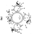
- Figure 1 is a schematic illustration of a printer according to an embodiment of the present invention.
- In relation to the appended drawings, the present invention is described in detail in the sequel. Several embodiments are disclosed. It is apparent however that a person skilled in the art can imagine several other equivalent embodiments or other ways of executing the present invention, the scope of the present invention being limited only by the terms of the appended claims.
- A printing system capable of printing on sheets of a recording medium is depicted in Fig. 1. The printing system comprises an image transfer member, which can be moved cyclically. The image transfer member is an endless member, such as e.g. a drum or a belt. In this case the image transfer member is a cylindrical drum (1), which can be moved in the direction of arrow (3). The image transfer member is constructed of a metal sleeve, e.g. aluminium, with an elastomeric covering (2). Optionally, the image transfer member may be provided with an outer layer of silicone rubber, e.g. by means of coating. One or more process colours are available on the printing system dependent whether it concerns a monochrome or a multi-colour printing system. For each process colour, an image forming unit (4)(5)(6) is disposed along the path of rotation of the intermediate transfer member. Each of these image forming units comprises a cylindrical image forming member (7) on which a colour separation image of the corresponding process is formed. In an operative state, the image forming members are all in pressure contact with the image transfer member, the force with which the image forming members are pressed against the image transfer member being at maximum 1000 N per linear meter, e.g. 250 N per linear meter.
Each image forming member is formed of a metal drum with a photo-conductive outer layer thereon, the various image forming devices being positioned along the circumference of the image forming member. These image forming devices comprise a charging device (11), e.g. a corona device, an exposing device (12), e.g. a LED array, for image-wise exposure of the photo-conductive surface to thereby form a latent charge image thereon, a development device (13) for developing the latent image with marking substance, a cleaning device (14) for removing any residual marking substance present on the image forming member after transfer of the developed separation image to the image transfer member. The development device is in this case a magnetic brush development device which comprises a magnetic roller (17) consisting of a rotatable sleeve with a stationary magnet system therein. The magnetic roller is positioned along the circumference of the image forming member with its surface at short distance from the image forming member surface without contacting it. A reservoir (18) with electrically conductive magnetically attractable dry particulate toner is positioned near the surface of each of the magnetic rollers (17). Each reservoir contains toner in one of the process colours. A stripper (19) is provided at each reservoir to ensure that an even layer of particulate toner is applied to the sleeve of the magnetic roller. - Also disposed along the path of rotation of the image transfer member (1) is a rotatable counter roller (23) which is selectively movable towards and away from the image transfer member surface with controlled pressure. Means (not shown) are provided to drive this counter member. When pressing the counter member against the image transfer member surface a transfer zone is defined through which in operation sheets of recording medium are passed using feed means and sheet discharging means. This feed means consists of co-operating conveyor rollers (21) and a guide plate (22). The sheet discharging means includes co-operating conveyor belts (24) (25).
- Further disposed along the path of rotation of the image transfer member (1) downstream of the transfer zone is a rotatable cleaning roller having a tacky surface. The cleaning roller (30) may be driven by drive means (not shown) and is selectively movable into and out-of an operative position in which the cleaning member surface is in contact with the image transfer member surface. A helical perforation is formed in the cleaning roller surface and extends to a cavity within the roller for discharging any contaminants and /or excess cleaning substance assembled on the roller surface therein. This helical perforation defines in the axial direction an alternating pattern of grooves and non-perforated areas, referred to as dams. Although these parameters are not that critical, the width and pitch of the perforation is of importance as they determine the ratio between the cleaning area and the non-cleaning area of the roller. As cleaning is only performed in the dam area and not in the grooves, proper consideration should be given when determining these parameters. A large cleaning area is desirable but account should be taken of the fact that the contaminants and/or excess cleaning substance assembled on the cleaning roller surface dams must be able to reach the grooves. Hence, for instance the viscosity of the cleaning substance should be involved in this consideration. A position sensor (not shown) is provided to detect the axial position and optionally also the radial position of the cleaning roller as well as control means (also not shown) for controlling the position of the cleaning roller responsive to the detected position.
- The tackiness of the surface layer of the cleaning roller may be improved and the viscosity of the layer may be adjusted by heating the surface layer upstream of the cleaning zone. To enable this, a heating device may be provided for heating the cleaning substance on the cleaning roller surface to render the surface tacky prior to contact thereof with the transfer member surface. The heating device may be in the form of a lamp located in the inner core of the roller. Alternatively, especially when the cleaning roller has a conformable surface, external heating is preferred, for example by use of an external radiant heat source. Ideally, means are provided for controlling the heating of the toner particles, for example by the use of a heat sensor to sense the temperature of the cleaning member surface, this sensor being coupled to a control device for the heating device. Heating the toner particles on the cleaning roller surface has several benefits. The heating device can be energized selectively to control the temperature and tackiness of the cleaning roller surface. This is especially beneficial at start up where, in the absence of such a heating device, it would take a significant amount of time (and possibly wastage of receiving material) before the temperature equilibria would be reached.
- In operation, in order to reproduce an image a sequence of printing signals is generated. Responsive to this sequence of printing signals the printing system sequentially forms the respective separation images of marking substance of the corresponding process colour on the respective image forming members (7). In the respective pressure contact zones, the respective separation images are sequentially transferred in register to the image transfer member to thereby form a registered multi-colour image thereon. The marking substance is toner in dry particulate form. The registered multi-colour toner image on the image transfer member is heated by means known per se so that the toner softens and is rendered tacky. The printing system is such that the respective separation images of marking particles are formed complementary. This means that marking particles of a process colour are accumulated on the free surface of the image-carrying member and substantially not on coloured marking particles already accumulated on the image-carrying member. Substantially not means that any superimposed marking particles of different process colours may not lead to visual deficiencies, i.e. visual with the naked human eye, in the finally printed image.
The printing system subsequently transfers the registered multi-colour toner image to a sheet of a recording medium which is controllably fed at the appropriate time by the conveyor rollers (21) through the transfer zone defined by establishing pressure contact between the rotating image transfer member and the rotating counter member. The sheet carrying the printed image is subsequently discharged by the co-operating conveyor belts (24) and (25). The image transfer member is further advanced towards the cleaning zone where any contaminants present on its surface may be removed by transferring them to the tacky surface of the rotating cleaning roller (30). When printing consecutive images, e.g. a document of several pages and/or plural copies of a single image or document, the printing job is defined such that the consecutive images are printed each on separate sheets fed in consecution through the transfer zone. Hence, for consecutive images both an inter-image area, being the area between consecutive images carried on the image transfer member, can be defined as well as an inter-sheet area, being the distance between the associated consecutive sheets. The part of the inter-image area coinciding with the inter-sheet area is referred to as the non-image area. According to the present invention a predetermined pattern of cleaning substance is formed in the non-image area. This may be done by imaging a predetermined pattern on the image forming member of one of the available process colours and subsequently developing it thereon with the corresponding toner. The toner, preferably black toner when available, used to form this predetermined pattern constitutes the cleaning substance. The image forming unit and the formation process of the predetermined pattern is controlled such that the transfer of the cleaning substance pattern to the image transfer member in the pressure contact zone is effected in the non-image area. When cleaning substance pattern in the non-image area reaches the transfer zone in the interval between two consecutive sheets, it can not be transferred to a sheet but instead will remain on the surface of the image transfer member or will be (partially) transferred to the counter member surface (23). When the image transfer member is moved further to the cleaning zone the cleaning substance pattern or at least the residual part thereof will be transferred to the dams of the tacky cleaning roller surface (30) thereby rejuvenating the tacky surface layer. To ensure that substantially all cleaning substance is removed from the image transfer member surface in the cleaning zone a pattern is selected which can be synchronised with the cleaning member using the cleaning roller position detection and controlling means such that cleaning substance is only present in the cleaning zone in the area coinciding with the dams of the cleaning roller. For example, when the pitch of the helical perforation is 3.5 mm and the groove width (dimension in axial direction) is 0.8 mm, typically a pattern is chosen having a dam width of about 1.1 mm which is well within the dam width of the cleaning roller. The dams of the pattern constitute the portions of the image transfer member surface in the non-image area covered with cleaning substance, while the dam width of the pattern is the width of the covered portions in the non-image area. - As stated before, when a cleaning substance pattern in a non-image area reaches the transfer zone in the interval between two consecutive sheets, it will remain on the surface of the image transfer member or will be (partially) transferred to the counter member surface (23). To avoid that the cleaning substance transferred to the counter member contaminates the back of subsequent sheets are transfers back to the image transfer members surface, a tacky surface cleaning roller (35) may also be provided to clean the counter member surface. Instead of providing the additional cleaning roller or in combination therewith, one can also opt to take appropriate measures to severely reduce or even nullify the transfer rate of cleaning substance to the counter member surface. One or these measures could be the use of a counter member surface layer having a lower affinity to cleaning substance compared to the image transfer member surface layer. Examples of such counter member surface layers are polyorganosiloxane layers, in particular the ones disclosed in EP0349072 (Schoustra et al., Océ Technologies B.V.). Instead or in addition to this measure, on could also opt to lower the area coverage of the portions of the image transfer member surface in the non-image area covered by the patterns of cleaning substance as it has been observed that this is beneficial to reduce the transfer rate of cleaning substance to the counter member surface. For instance the area coverage may be chosen typically in the range from 1% to 30%, or from 1% to 10%, or from 1% to 5%.
characterised in that the device further comprises
a controllable applicator unit for providing, in an operative state of the image transfer device, predetermined patterns of a cleaning substance to the surface of the image transfer member in at least some non-image areas, the predetermined patterns of cleaning substance on the image transfer member being substantially completely transferred to the surface of the cleaning member in the cleaning zone. The present invention is particularly relevant to printers and copiers where, to enable printing on a wide variety of recording media, at least one image transfer device is provided to transfer an image of marking substance from an image forming device to the recording medium. The feature that non-image patterns of cleaning substance can be formed in the non-image areas being the areas between consecutive images coinciding with the areas between consecutive sheets is advantageous as it allows to rejuvenate the cleaning member surface quasi continuously. Furthermore, as this takes place in the operative state, i.e. while sheets of recording medium are fed through the transfer zone and hence prints or copies of images are generated, this rejuvenation process does not negatively affect the productivity of the printer or copier.
characterised in that the method further comprises receiving patterns of a cleaning substance on the image transfer member in at least some non-image areas, between at least some of the consecutive images, the non-image areas being the areas between consecutive images coinciding with the areas between consecutive sheets, the non-image patterns of cleaning substance being substantially completely transferred to the surface of the cleaning member in the cleaning zone.
Claims (10)
- An image transfer device for transferring images of a marking substance to sheets of a recording medium, the device comprising:an endless image transfer member for receiving consecutive images of a marking substance on its surface, the image transfer member being urged, in an operative state of the transfer device, into moving contact with a counter member to form a transfer zone therebetween for transferring the respective consecutive images to respective sheets of a recording medium fed consecutively through the transfer zone;an endless cleaning member having, in an operative state of the image transfer device, a surface in moving contact with the surface of the image transfer member in a cleaning zone downstream of the transfer zone, the surface of the cleaning member carrying a layer of tacky substance; anda controllable applicator unit for providing, in an operative state of the image transfer device, predetermined patterns of a cleaning substance to the surface of the image transfer member,
characterised in that, in an operative state of the image transfer device,
the predetermined patterns of cleaning substance are provided to the surface of the image transfer member upstream to the transfer zone in at least some non-image areas, being the areas between consecutive images coinciding with the areas between consecutive sheets, the predetermined patterns of cleaning substance on the image transfer member being guided through the transfer zone, while the image transfer member is urged against the counter member, towards the cleaning zone where they are substantially completely transferred to the surface of the cleaning member. - An image transfer device according to claim 1, wherein the cleaning member is a cleaning roller having a surface with a plurality of spaced-apart perforations therein for discharging any contaminants and excess cleaning substance assembled on the cleaning roller surface.
- An image transfer device according to claim 2, wherein the perforations are grooves.
- An image transfer device according to claims 2 and 3, further comprising means for synchronizing the position of the perforations and the predetermined patterns of cleaning substance to ensure that in the cleaning zone cleaning substance is only present on the image transfer member surface outside the perforations.
- An image transfer device according to claim 4, wherein said means for synchronizing the position include a position sensor for determining the axial position of the cleaning member.
- An image transfer device according to any preceding claim, wherein the portions of the image transfer member surface, covered by the patterns of cleaning substance, have an area coverage in the range from 1% to 30%.
- An image transfer device according to any preceding claim, wherein the counter member has an outer layer of a silicone elastomer, or a PTFE, or a fluororubber, and the image transfer member has an outer layer of a silicone elastomer.
- An image transfer device according any preceding claim, wherein the image transfer member is in the form of a belt and the cleaning member cooperates with a backing roller to form the cleaning zone through which the belt passes.
- An image transfer device according to any preceding claim, wherein said cleaning substance comprises a polymer having a glass transition temperature below the temperature of the surface of the image transfer member at the cleaning zone.
- A method of removing contaminants from the surface of an endless image transfer member of an image transfer device in which in operation the endless image transfer member is urged into contact with a counter member to form a transfer zone therebetween through which consecutive sheets of a recording medium are fed, the method comprising:contacting the image transfer member surface at a cleaning zone downstream the transfer zone with an endless cleaning member having a tacky surface layer of cleaning substance, thereby to transfer contaminants from the image transfer member to the tacky surface;receiving consecutive images of a marking substance on the image transfer member; andreceiving patterns of a cleaning substance on the image transfer member;
characterised in that the patterns of cleaning substance are received on the image transfer member in at least some non-image areas, the non-image areas being the areas between the consecutive images coinciding with the areas between consecutive sheets, the method further comprising guiding the image transfer member via the transfer zone, where the respective consecutive images are transferred to the respective consecutive sheets, to the cleaning zone where the non-image patterns of cleaning substance are substantially completely transferred to the surface of the cleaning member.
Priority Applications (1)
| Application Number | Priority Date | Filing Date | Title |
|---|---|---|---|
| EP20050107553 EP1632821B1 (en) | 2004-09-01 | 2005-08-17 | Intermediate transfer member with a cleaning member |
Applications Claiming Priority (2)
| Application Number | Priority Date | Filing Date | Title |
|---|---|---|---|
| EP04077445 | 2004-09-01 | ||
| EP20050107553 EP1632821B1 (en) | 2004-09-01 | 2005-08-17 | Intermediate transfer member with a cleaning member |
Publications (2)
| Publication Number | Publication Date |
|---|---|
| EP1632821A1 true EP1632821A1 (en) | 2006-03-08 |
| EP1632821B1 EP1632821B1 (en) | 2012-05-30 |
Family
ID=35809965
Family Applications (1)
| Application Number | Title | Priority Date | Filing Date |
|---|---|---|---|
| EP20050107553 Expired - Lifetime EP1632821B1 (en) | 2004-09-01 | 2005-08-17 | Intermediate transfer member with a cleaning member |
Country Status (1)
| Country | Link |
|---|---|
| EP (1) | EP1632821B1 (en) |
Cited By (2)
| Publication number | Priority date | Publication date | Assignee | Title |
|---|---|---|---|---|
| EP2120102A1 (en) | 2008-05-15 | 2009-11-18 | Océ-Technologies B.V. | Method of cleaning a toner image carrier |
| CN111868636A (en) * | 2018-03-21 | 2020-10-30 | 惠普发展公司,有限责任合伙企业 | Cleaning the surface of the printing unit |
Citations (5)
| Publication number | Priority date | Publication date | Assignee | Title |
|---|---|---|---|---|
| US4607947A (en) * | 1983-11-30 | 1986-08-26 | Oce-Nederland B.V. | Contact fixing and cleaning method and apparatus |
| US4705388A (en) | 1985-05-09 | 1987-11-10 | Oce-Nederland B.V. | Method and apparatus for determining when a layer of tacky material present on a cleaning member needs to be rejuvenated |
| EP0349072A1 (en) | 1988-07-01 | 1990-01-03 | Océ-Nederland B.V. | A device for fixing or transferring and fixing powder containing thermoplastic resin on to a receiving material |
| EP0994861A1 (en) | 1997-06-19 | 2000-04-26 | Basf Aktiengesellschaft | NEW $g(b)-AMINO AND $g(b)-AZIDOCARBOXYLIC ACID DERIVATIVES, THE PRODUCTION THEREOF AND THE USE THEREOF AS ENDOTHELIN RECEPTOR ANTAGONISTS |
| US6226489B1 (en) | 1999-01-23 | 2001-05-01 | Xeikon Nv | Fixing device for fixing toner images onto a receiving material |
-
2005
- 2005-08-17 EP EP20050107553 patent/EP1632821B1/en not_active Expired - Lifetime
Patent Citations (5)
| Publication number | Priority date | Publication date | Assignee | Title |
|---|---|---|---|---|
| US4607947A (en) * | 1983-11-30 | 1986-08-26 | Oce-Nederland B.V. | Contact fixing and cleaning method and apparatus |
| US4705388A (en) | 1985-05-09 | 1987-11-10 | Oce-Nederland B.V. | Method and apparatus for determining when a layer of tacky material present on a cleaning member needs to be rejuvenated |
| EP0349072A1 (en) | 1988-07-01 | 1990-01-03 | Océ-Nederland B.V. | A device for fixing or transferring and fixing powder containing thermoplastic resin on to a receiving material |
| EP0994861A1 (en) | 1997-06-19 | 2000-04-26 | Basf Aktiengesellschaft | NEW $g(b)-AMINO AND $g(b)-AZIDOCARBOXYLIC ACID DERIVATIVES, THE PRODUCTION THEREOF AND THE USE THEREOF AS ENDOTHELIN RECEPTOR ANTAGONISTS |
| US6226489B1 (en) | 1999-01-23 | 2001-05-01 | Xeikon Nv | Fixing device for fixing toner images onto a receiving material |
Cited By (5)
| Publication number | Priority date | Publication date | Assignee | Title |
|---|---|---|---|---|
| EP2120102A1 (en) | 2008-05-15 | 2009-11-18 | Océ-Technologies B.V. | Method of cleaning a toner image carrier |
| US8265539B2 (en) | 2008-05-15 | 2012-09-11 | Oce-Technologies B.V. | Method of cleaning a toner image carrier |
| CN111868636A (en) * | 2018-03-21 | 2020-10-30 | 惠普发展公司,有限责任合伙企业 | Cleaning the surface of the printing unit |
| CN111868636B (en) * | 2018-03-21 | 2023-09-05 | 惠普发展公司,有限责任合伙企业 | Clean the surface of the printing unit |
| US11860557B2 (en) | 2018-03-21 | 2024-01-02 | Hewlett-Packard Development Company, L.P. | Cleaning surfaces for print apparatus |
Also Published As
| Publication number | Publication date |
|---|---|
| EP1632821B1 (en) | 2012-05-30 |
Similar Documents
| Publication | Publication Date | Title |
|---|---|---|
| US20080112734A1 (en) | Belt device and image forming apparatus | |
| US20070019996A1 (en) | Method and apparatus for improving image transfer in liquid electrostatic printing | |
| KR20080047803A (en) | Image Forming Device | |
| WO2012003807A1 (en) | Electrostatic dry powder transfer printing apparatus and method for large format printing by using same | |
| EP0698832B1 (en) | Prevention of excess liquid toner contamination in the formation of electrophotographic images | |
| US20080226335A1 (en) | Image transfer device and method for cleaning a part thereof | |
| JP3868135B2 (en) | Release agent management structure, heat and pressure fixing device, and release agent supply method | |
| EP1632821B1 (en) | Intermediate transfer member with a cleaning member | |
| EP1096333A1 (en) | Fixing device and method comprising a cleaning roller | |
| US7269375B2 (en) | Image transfer device and method for cleaning a part thereof | |
| JP4090524B2 (en) | Release agent metering method and metering device | |
| US4339194A (en) | Cold pressure fusing apparatus | |
| JPH08234614A (en) | Color transparent body fixing device and structure having streak removing step | |
| EP0532235B1 (en) | Spring loaded oil distributing preheated donor roll | |
| US12429815B2 (en) | Method for cooling down a printer, printer and software product | |
| US5905929A (en) | Electrophotographic printer | |
| US6097920A (en) | Recording apparatus and method including intermediate transfer medium | |
| US6032014A (en) | Method of using an image forming apparatus | |
| JP4686223B2 (en) | Image forming apparatus and process cartridge | |
| EP0848304A2 (en) | Device and method for fixing and glossing toner images | |
| US7505721B2 (en) | Image registration device | |
| JPH05232841A (en) | Glossy image forming device | |
| US6014537A (en) | Method of developing an image in an image forming apparatus | |
| DE69326209T2 (en) | Imaging device | |
| WO2009005653A1 (en) | Self-cleaning electrophotographic toning roller system |
Legal Events
| Date | Code | Title | Description |
|---|---|---|---|
| PUAI | Public reference made under article 153(3) epc to a published international application that has entered the european phase |
Free format text: ORIGINAL CODE: 0009012 |
|
| AK | Designated contracting states |
Kind code of ref document: A1 Designated state(s): AT BE BG CH CY CZ DE DK EE ES FI FR GB GR HU IE IS IT LI LT LU LV MC NL PL PT RO SE SI SK TR |
|
| AX | Request for extension of the european patent |
Extension state: AL BA HR MK YU |
|
| 17P | Request for examination filed |
Effective date: 20060908 |
|
| 17Q | First examination report despatched |
Effective date: 20061012 |
|
| AKX | Designation fees paid |
Designated state(s): AT BE BG CH CY CZ DE DK EE ES FI FR GB GR HU IE IS IT LI LT LU LV MC NL PL PT RO SE SI SK TR |
|
| GRAP | Despatch of communication of intention to grant a patent |
Free format text: ORIGINAL CODE: EPIDOSNIGR1 |
|
| GRAS | Grant fee paid |
Free format text: ORIGINAL CODE: EPIDOSNIGR3 |
|
| GRAA | (expected) grant |
Free format text: ORIGINAL CODE: 0009210 |
|
| AK | Designated contracting states |
Kind code of ref document: B1 Designated state(s): AT BE BG CH CY CZ DE DK EE ES FI FR GB GR HU IE IS IT LI LT LU LV MC NL PL PT RO SE SI SK TR |
|
| REG | Reference to a national code |
Ref country code: GB Ref legal event code: FG4D |
|
| REG | Reference to a national code |
Ref country code: CH Ref legal event code: EP |
|
| REG | Reference to a national code |
Ref country code: AT Ref legal event code: REF Ref document number: 560326 Country of ref document: AT Kind code of ref document: T Effective date: 20120615 |
|
| REG | Reference to a national code |
Ref country code: IE Ref legal event code: FG4D |
|
| REG | Reference to a national code |
Ref country code: DE Ref legal event code: R096 Ref document number: 602005034391 Country of ref document: DE Effective date: 20120802 |
|
| REG | Reference to a national code |
Ref country code: NL Ref legal event code: T3 |
|
| REG | Reference to a national code |
Ref country code: LT Ref legal event code: MG4D Effective date: 20120530 |
|
| PG25 | Lapsed in a contracting state [announced via postgrant information from national office to epo] |
Ref country code: SE Free format text: LAPSE BECAUSE OF FAILURE TO SUBMIT A TRANSLATION OF THE DESCRIPTION OR TO PAY THE FEE WITHIN THE PRESCRIBED TIME-LIMIT Effective date: 20120530 Ref country code: LT Free format text: LAPSE BECAUSE OF FAILURE TO SUBMIT A TRANSLATION OF THE DESCRIPTION OR TO PAY THE FEE WITHIN THE PRESCRIBED TIME-LIMIT Effective date: 20120530 Ref country code: FI Free format text: LAPSE BECAUSE OF FAILURE TO SUBMIT A TRANSLATION OF THE DESCRIPTION OR TO PAY THE FEE WITHIN THE PRESCRIBED TIME-LIMIT Effective date: 20120530 Ref country code: CY Free format text: LAPSE BECAUSE OF FAILURE TO SUBMIT A TRANSLATION OF THE DESCRIPTION OR TO PAY THE FEE WITHIN THE PRESCRIBED TIME-LIMIT Effective date: 20120530 Ref country code: IS Free format text: LAPSE BECAUSE OF FAILURE TO SUBMIT A TRANSLATION OF THE DESCRIPTION OR TO PAY THE FEE WITHIN THE PRESCRIBED TIME-LIMIT Effective date: 20120930 |
|
| REG | Reference to a national code |
Ref country code: AT Ref legal event code: MK05 Ref document number: 560326 Country of ref document: AT Kind code of ref document: T Effective date: 20120530 |
|
| PG25 | Lapsed in a contracting state [announced via postgrant information from national office to epo] |
Ref country code: LV Free format text: LAPSE BECAUSE OF FAILURE TO SUBMIT A TRANSLATION OF THE DESCRIPTION OR TO PAY THE FEE WITHIN THE PRESCRIBED TIME-LIMIT Effective date: 20120530 Ref country code: SI Free format text: LAPSE BECAUSE OF FAILURE TO SUBMIT A TRANSLATION OF THE DESCRIPTION OR TO PAY THE FEE WITHIN THE PRESCRIBED TIME-LIMIT Effective date: 20120530 Ref country code: GR Free format text: LAPSE BECAUSE OF FAILURE TO SUBMIT A TRANSLATION OF THE DESCRIPTION OR TO PAY THE FEE WITHIN THE PRESCRIBED TIME-LIMIT Effective date: 20120831 |
|
| PG25 | Lapsed in a contracting state [announced via postgrant information from national office to epo] |
Ref country code: BE Free format text: LAPSE BECAUSE OF FAILURE TO SUBMIT A TRANSLATION OF THE DESCRIPTION OR TO PAY THE FEE WITHIN THE PRESCRIBED TIME-LIMIT Effective date: 20120530 |
|
| PG25 | Lapsed in a contracting state [announced via postgrant information from national office to epo] |
Ref country code: DK Free format text: LAPSE BECAUSE OF FAILURE TO SUBMIT A TRANSLATION OF THE DESCRIPTION OR TO PAY THE FEE WITHIN THE PRESCRIBED TIME-LIMIT Effective date: 20120530 Ref country code: AT Free format text: LAPSE BECAUSE OF FAILURE TO SUBMIT A TRANSLATION OF THE DESCRIPTION OR TO PAY THE FEE WITHIN THE PRESCRIBED TIME-LIMIT Effective date: 20120530 Ref country code: RO Free format text: LAPSE BECAUSE OF FAILURE TO SUBMIT A TRANSLATION OF THE DESCRIPTION OR TO PAY THE FEE WITHIN THE PRESCRIBED TIME-LIMIT Effective date: 20120530 Ref country code: SK Free format text: LAPSE BECAUSE OF FAILURE TO SUBMIT A TRANSLATION OF THE DESCRIPTION OR TO PAY THE FEE WITHIN THE PRESCRIBED TIME-LIMIT Effective date: 20120530 Ref country code: CZ Free format text: LAPSE BECAUSE OF FAILURE TO SUBMIT A TRANSLATION OF THE DESCRIPTION OR TO PAY THE FEE WITHIN THE PRESCRIBED TIME-LIMIT Effective date: 20120530 Ref country code: EE Free format text: LAPSE BECAUSE OF FAILURE TO SUBMIT A TRANSLATION OF THE DESCRIPTION OR TO PAY THE FEE WITHIN THE PRESCRIBED TIME-LIMIT Effective date: 20120530 |
|
| PG25 | Lapsed in a contracting state [announced via postgrant information from national office to epo] |
Ref country code: PL Free format text: LAPSE BECAUSE OF FAILURE TO SUBMIT A TRANSLATION OF THE DESCRIPTION OR TO PAY THE FEE WITHIN THE PRESCRIBED TIME-LIMIT Effective date: 20120530 Ref country code: IT Free format text: LAPSE BECAUSE OF FAILURE TO SUBMIT A TRANSLATION OF THE DESCRIPTION OR TO PAY THE FEE WITHIN THE PRESCRIBED TIME-LIMIT Effective date: 20120530 Ref country code: PT Free format text: LAPSE BECAUSE OF FAILURE TO SUBMIT A TRANSLATION OF THE DESCRIPTION OR TO PAY THE FEE WITHIN THE PRESCRIBED TIME-LIMIT Effective date: 20121001 |
|
| REG | Reference to a national code |
Ref country code: CH Ref legal event code: PL |
|
| PG25 | Lapsed in a contracting state [announced via postgrant information from national office to epo] |
Ref country code: MC Free format text: LAPSE BECAUSE OF NON-PAYMENT OF DUE FEES Effective date: 20120831 |
|
| PLBE | No opposition filed within time limit |
Free format text: ORIGINAL CODE: 0009261 |
|
| STAA | Information on the status of an ep patent application or granted ep patent |
Free format text: STATUS: NO OPPOSITION FILED WITHIN TIME LIMIT |
|
| PG25 | Lapsed in a contracting state [announced via postgrant information from national office to epo] |
Ref country code: ES Free format text: LAPSE BECAUSE OF FAILURE TO SUBMIT A TRANSLATION OF THE DESCRIPTION OR TO PAY THE FEE WITHIN THE PRESCRIBED TIME-LIMIT Effective date: 20120910 Ref country code: CH Free format text: LAPSE BECAUSE OF NON-PAYMENT OF DUE FEES Effective date: 20120831 Ref country code: LI Free format text: LAPSE BECAUSE OF NON-PAYMENT OF DUE FEES Effective date: 20120831 |
|
| 26N | No opposition filed |
Effective date: 20130301 |
|
| REG | Reference to a national code |
Ref country code: IE Ref legal event code: MM4A |
|
| REG | Reference to a national code |
Ref country code: DE Ref legal event code: R097 Ref document number: 602005034391 Country of ref document: DE Effective date: 20130301 |
|
| PG25 | Lapsed in a contracting state [announced via postgrant information from national office to epo] |
Ref country code: BG Free format text: LAPSE BECAUSE OF FAILURE TO SUBMIT A TRANSLATION OF THE DESCRIPTION OR TO PAY THE FEE WITHIN THE PRESCRIBED TIME-LIMIT Effective date: 20120830 Ref country code: IE Free format text: LAPSE BECAUSE OF NON-PAYMENT OF DUE FEES Effective date: 20120817 |
|
| PG25 | Lapsed in a contracting state [announced via postgrant information from national office to epo] |
Ref country code: TR Free format text: LAPSE BECAUSE OF FAILURE TO SUBMIT A TRANSLATION OF THE DESCRIPTION OR TO PAY THE FEE WITHIN THE PRESCRIBED TIME-LIMIT Effective date: 20120530 |
|
| PG25 | Lapsed in a contracting state [announced via postgrant information from national office to epo] |
Ref country code: LU Free format text: LAPSE BECAUSE OF NON-PAYMENT OF DUE FEES Effective date: 20120817 |
|
| PG25 | Lapsed in a contracting state [announced via postgrant information from national office to epo] |
Ref country code: HU Free format text: LAPSE BECAUSE OF FAILURE TO SUBMIT A TRANSLATION OF THE DESCRIPTION OR TO PAY THE FEE WITHIN THE PRESCRIBED TIME-LIMIT Effective date: 20050817 |
|
| REG | Reference to a national code |
Ref country code: FR Ref legal event code: PLFP Year of fee payment: 12 |
|
| PGFP | Annual fee paid to national office [announced via postgrant information from national office to epo] |
Ref country code: NL Payment date: 20160817 Year of fee payment: 12 |
|
| PGFP | Annual fee paid to national office [announced via postgrant information from national office to epo] |
Ref country code: GB Payment date: 20160819 Year of fee payment: 12 Ref country code: DE Payment date: 20160822 Year of fee payment: 12 |
|
| PGFP | Annual fee paid to national office [announced via postgrant information from national office to epo] |
Ref country code: FR Payment date: 20160822 Year of fee payment: 12 |
|
| REG | Reference to a national code |
Ref country code: DE Ref legal event code: R119 Ref document number: 602005034391 Country of ref document: DE |
|
| REG | Reference to a national code |
Ref country code: NL Ref legal event code: MM Effective date: 20170901 |
|
| GBPC | Gb: european patent ceased through non-payment of renewal fee |
Effective date: 20170817 |
|
| REG | Reference to a national code |
Ref country code: FR Ref legal event code: ST Effective date: 20180430 |
|
| PG25 | Lapsed in a contracting state [announced via postgrant information from national office to epo] |
Ref country code: NL Free format text: LAPSE BECAUSE OF NON-PAYMENT OF DUE FEES Effective date: 20170901 |
|
| PG25 | Lapsed in a contracting state [announced via postgrant information from national office to epo] |
Ref country code: DE Free format text: LAPSE BECAUSE OF NON-PAYMENT OF DUE FEES Effective date: 20180301 Ref country code: GB Free format text: LAPSE BECAUSE OF NON-PAYMENT OF DUE FEES Effective date: 20170817 |
|
| PG25 | Lapsed in a contracting state [announced via postgrant information from national office to epo] |
Ref country code: FR Free format text: LAPSE BECAUSE OF NON-PAYMENT OF DUE FEES Effective date: 20170831 |