EP1632673A1 - Pulse detonation system for a gas turbine engine having multiple spools - Google Patents
Pulse detonation system for a gas turbine engine having multiple spools Download PDFInfo
- Publication number
- EP1632673A1 EP1632673A1 EP05255345A EP05255345A EP1632673A1 EP 1632673 A1 EP1632673 A1 EP 1632673A1 EP 05255345 A EP05255345 A EP 05255345A EP 05255345 A EP05255345 A EP 05255345A EP 1632673 A1 EP1632673 A1 EP 1632673A1
- Authority
- EP
- European Patent Office
- Prior art keywords
- detonation
- gas turbine
- turbine engine
- drive shaft
- rotatable
- Prior art date
- Legal status (The legal status is an assumption and is not a legal conclusion. Google has not performed a legal analysis and makes no representation as to the accuracy of the status listed.)
- Granted
Links
- 238000005474 detonation Methods 0.000 title claims abstract description 265
- 239000007789 gas Substances 0.000 claims description 60
- 239000000446 fuel Substances 0.000 claims description 38
- 230000000977 initiatory effect Effects 0.000 claims description 21
- 238000004891 communication Methods 0.000 claims description 13
- 239000000567 combustion gas Substances 0.000 claims description 10
- 238000000034 method Methods 0.000 description 10
- 238000011144 upstream manufacturing Methods 0.000 description 5
- 230000007704 transition Effects 0.000 description 4
- 238000002347 injection Methods 0.000 description 3
- 239000007924 injection Substances 0.000 description 3
- 230000001419 dependent effect Effects 0.000 description 2
- 238000012423 maintenance Methods 0.000 description 2
- 239000007800 oxidant agent Substances 0.000 description 2
- 230000035939 shock Effects 0.000 description 2
- 239000013598 vector Substances 0.000 description 2
- 230000001154 acute effect Effects 0.000 description 1
- 239000003570 air Substances 0.000 description 1
- 230000000694 effects Effects 0.000 description 1
- 239000002737 fuel gas Substances 0.000 description 1
- 238000004519 manufacturing process Methods 0.000 description 1
Images


Classifications
-
- F—MECHANICAL ENGINEERING; LIGHTING; HEATING; WEAPONS; BLASTING
- F02—COMBUSTION ENGINES; HOT-GAS OR COMBUSTION-PRODUCT ENGINE PLANTS
- F02K—JET-PROPULSION PLANTS
- F02K7/00—Plants in which the working fluid is used in a jet only, i.e. the plants not having a turbine or other engine driving a compressor or a ducted fan; Control thereof
- F02K7/005—Plants in which the working fluid is used in a jet only, i.e. the plants not having a turbine or other engine driving a compressor or a ducted fan; Control thereof the engine comprising a rotor rotating under the actions of jets issuing from this rotor
-
- Y—GENERAL TAGGING OF NEW TECHNOLOGICAL DEVELOPMENTS; GENERAL TAGGING OF CROSS-SECTIONAL TECHNOLOGIES SPANNING OVER SEVERAL SECTIONS OF THE IPC; TECHNICAL SUBJECTS COVERED BY FORMER USPC CROSS-REFERENCE ART COLLECTIONS [XRACs] AND DIGESTS
- Y02—TECHNOLOGIES OR APPLICATIONS FOR MITIGATION OR ADAPTATION AGAINST CLIMATE CHANGE
- Y02T—CLIMATE CHANGE MITIGATION TECHNOLOGIES RELATED TO TRANSPORTATION
- Y02T50/00—Aeronautics or air transport
- Y02T50/60—Efficient propulsion technologies, e.g. for aircraft
Definitions
- the present invention relates generally to a pulse detonation system for a gas turbine engine and, in particular, to a pulse detonation system which is able to replace the core of a gas turbine engine and separately power the fan and booster compressor thereof.
- the pulse detonation device includes a stationary air inlet duct and a ring member which rotates therearound.
- the various events of the detonation take place within detonation ducts associated with the ring member, as air and fuel are injected and a detonation wave is initiated therein.
- the aft portion of the rotatable ring member is connected to a drive shaft in a cantilevered manner.
- the air ports, fuel injectors and initiation devices are located adjacent an outer surface of the air inlet duct so as to be sequentially aligned with an inner end of the detonation ducts, which are open at each end, as the ring member rotates.
- a second type of pulse detonation system owned by the assignee of the present invention is disclosed in a patent application entitled "Rotating Pulse Detonation System For A Gas Turbine Engine” having Serial No. 10/422,314.
- This system discloses a rotatable cylindrical member having a forward surface, an aft surface, and an outer circumferential surface, where a plurality of spaced detonation passages are disposed therethrough.
- each detonation passage includes at least a portion thereof with a longitudinal axis extending therethrough oriented at a circumferential angle to a longitudinal centerline axis through the gas turbine engine.
- the pulse detonation system also includes a shaft rotatably connected to the cylindrical member and a stator is configured in spaced arrangement with the forward surface of the cylindrical member and a portion of the shaft.
- the stator further includes at least one group of ports formed therein alignable with the detonation passages as the cylindrical member rotates. In this way, detonation cycles are performed in the detonation passages so that combustion gases exit the aft surface of the cylindrical member to create a torque which causes the cylindrical member to rotate.
- Pulse Detonation System owned by the assignee of the current invention is disclosed in a patent application entitled "Rotary Pulse Detonation System With Aerodynamic Detonation Passages For Use In A Gas Turbine Engine," having Serial No. 10/803,293.
- the pulse detonation system described therein includes a rotatable cylindrical member having a forward surface, an aft surface, and an outer circumferential surface, where at least one stage of circumferentially spaced detonation passages are disposed therethrough.
- Each detonation passage further includes: a leading portion positioned adjacent the forward surface of the cylindrical member, with the leading portion having a centerline therethrough oriented at a designated angle to an axis extending substantially parallel to the longitudinal centerline axis within a specified plane; a trailing portion positioned adjacent the aft surface of the cylindrical member, with the trailing portion having a centerline therethrough oriented at a designated angle to the axis within the specified plane; and, a middle portion connecting the leading and trailing portions, with the middle portion having a centerline therethrough with a substantially constantly changing slope in the specified plane.
- a shaft is rotatably connected to the cylindrical member and a stator is configured in spaced arrangement with the forward surface of the cylindrical member and a portion of the shaft.
- the stator further includes at least one group of ports formed therein alignable with the leading portions of the detonation passages as the cylindrical member rotates. In this way, detonation cycles are performed in the detonation passages so that combustion gases interact therewith to create a torque which causes the cylindrical member to rotate.
- a pulse detonation system to be developed for a gas turbine engine which is able to operate the engine without the need for a separate valve. Further, it would be desirable for such pulse detonation system to be modified so that it is able to separately start the booster compressor from the fan of the gas turbine engine.
- a gas turbine engine having a longitudinal centerline axis therethrough including: a fan section at a forward end of the gas turbine engine including at least a first fan blade row connected to a first drive shaft; a booster compressor positioned downstream of the fan section, the booster compressor including a first compressor blade row and a second compressor blade row connected to a second drive shaft and interdigitated with the first compressor blade row; and, a pulse detonation system for powering the first and second drive shafts.
- the pulse detonation system powers only the second drive shaft during a first designated condition of the gas turbine engine and both the first drive shaft and the second drive shaft during a second designated condition of the gas turbine engine.
- the first and second drive shafts are powered independently of each other by the pulse detonation system.
- a method of independently powering separate drive shafts in a gas turbine engine by means of a pulse detonation system including the following steps: providing a first rotatable member with a plurality of detonation areas associated therewith; connecting the first rotatable member to a first drive shaft of the gas turbine engine; providing a second rotatable member with a plurality of detonation areas associated therewith; connecting the second rotatable member to a second drive shaft of the gas turbine engine; producing a torque on the first rotatable member via the performance of pulse detonation cycles in the detonation areas thereof during a first designated condition of the gas turbine engine; and, producing a torque on the first and second rotatable members via the performance of pulse detonation cycles in the detonation areas thereof during a second designated condition of the gas turbine engine.
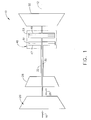
- Fig. 1 schematically depicts a gas turbine engine 10 utilized with aircraft having a longitudinal or axial centerline axis 12 therethrough for reference purposes.
- gas turbine engine 10 preferably includes a nacelle 14 to assist in directing a flow of air (represented by arrow 16) through an inlet 18 to a fan section 20 as is well known. Air flow 16 is then split downstream of fan section 20 so that a first portion (represented by arrow 22) flows through an outer duct 24 and a second portion (represented by arrow 26) is provided to a booster compressor 28.
- a first fan blade row 44 is preferably connected to a first drive shaft 32.
- booster compressor 28 preferably includes at least a first compressor blade row 30, which preferably is stationary, and a second compressor blade row 34 connected to a second drive shaft 33 and interdigitated with first compressor blade row 30. It will be appreciated that additional compressor blade rows 36 and 38 may also be connected to second drive shaft 33, with additional stationary compressor blade rows 40 and 42 being interdigitated therewith, respectively.
- First and second drive shafts 32 and 33, respectively, are powered by means of a pulse detonation system 46 in accordance with the present invention.
- pulse detonation system 46 will preferably initially power only second drive shaft 33 during a first designated condition of gas turbine engine 10 (e.g., start-up of gas turbine engine 10). Because second drive shaft 33 serves to cause the rotation of booster compressor 28, the much higher starting torque required by fan section 20 need not be extracted from pulse detonation system 46 during this first designated condition of gas turbine engine 10. Once booster compressor 28 rotates at a predetermined rotational speed (i.e., a second designated operating condition of gas turbine engine 10), pulse detonation system 46 is then preferably utilized to power first drive shaft 32 and cause rotation of fan section 20, as well as second drive shaft 33.
- a predetermined rotational speed i.e., a second designated operating condition of gas turbine engine 10
- booster compressor 28 can supply the compressed air required by pulse detonation system 46 when the higher starting torque of fan section 20 is required. Due to their coaxial relation, first and second drive shafts 32 and 33 are able to be driven independently.
- pulse detonation system 46 may be configured in any of several different ways, it will generally be understood from Fig. 1 that a first rotatable section 47 is provided for powering second drive shaft 33 and a second rotatable section 49 is provided for powering first drive shaft 32. First rotatable section 47 will typically be located upstream of second rotatable section 49, although the connection of first and second drive shafts 32 and 33 with pulse detonation system 46 may allow first rotatable section 47 to be located downstream of second rotatable section 49.
- First rotatable section 47 will generally include a single stage 51, but may include additional stages depending upon the starting requirements of booster compressor 28 and the torque produced by each such stage of first rotatable section 47.
- second rotatable section 49 typically will have a plurality of stages 53 incorporated therewith.
- second rotatable section 49 of pulse detonation system 46 can be tuned to the requirements of operating gas turbine engine 10 during any particular point in the engine cycle while maximizing the efficiency of pulse detonation system 46. This is accomplished through the performance of detonation cycles within only those stages of second rotatable section 49 (and possibly only portions of such stages) that are needed to accomplish the desired torque in fan section 20.
- gas turbine engine 10 may further include a turbine 55 positioned aft of and in flow communication with pulse detonation system 46.
- Such turbine 55 would also preferably be connected to first drive shaft 32 so as to assist in powering fan section 20.
- Turbine 55 would therefore preferably be driven by the gas products exiting pulse detonation system 46 and, particularly, second rotatable section 49. Implementation of turbine 55 with pulse detonation system 46 would serve to increase the efficiency of gas turbine engine 10 instead of merely allowing the products from pulse detonation system to exit unused.
- pulse detonation system 46 is generally described in the '027 patent application, which is hereby incorporated by reference.
- this configuration of pulse detonation system 46 includes an air inlet duct 48 which is positioned so as to be in flow communication with booster compressor 28.
- Air inlet duct 48 includes at least one port 50 formed therein for permitting compressed air received from booster compressor 28 to flow therethrough.
- a fuel injector 52 is mounted to air inlet duct 48 in circumferentially spaced relation to each port 50 and a device 54 is mounted to air inlet duct 48 in circumferentially spaced relation to each fuel injector 52 for initiating detonation waves.
- initiation device 54 may include, for example, an igniter (e.g., a high energy spark plug, a torch igniter having separate fuel and oxidizer, or a plasma jet igniter), a laser, or a shock focus device.
- a first rotatable ring member 56 (corresponding to first rotatable member 47 in Fig. 1) is preferably positioned in coaxial relation (with respect to centerline longitudinal axis 12) around an upstream portion of air inlet duct 48.
- First rotatable ring member 56 includes at least one detonation stage 58 disposed therein, although additional detonation stages may be provided therein in spaced axial relation downstream of detonation stage 58 depending upon the torque requirements of booster compressor 28.
- a second rotatable ring member 57 (corresponding to second rotatable member 49 in Fig. 1) is preferably positioned in coaxial relation around a downstream portion of air inlet duct 48.
- Second rotatable ring member 57 preferably includes a plurality of detonation stages 59 disposed therein in spaced axial relation due to the high starting torque requirements of fan section 20.
- Each detonation stage of first rotatable ring member 56 and second rotatable ring member 57 preferably has a plurality of circumferentially spaced detonation ducts 66 and 67, respectively, extending tangentially from an inner surface 74 of first rotatable ring member 56 and an inner surface 75 of second rotatable ring member 57 in a distinct radial plane. It is also preferred that first and second rotatable ring members 56 and 57 be hollow between each adjacent detonation duct 66 and each adjacent detonation duct 67 so as to reduce weight, thereby giving detonation ducts 66 and 67 a tube-like appearance. In order to provide added stability, various connections may be provided between adjacent detonation ducts 66 and between adjacent detonation ducts 67. An alternative configuration may involve a ring member having tubes attached to an outer surface thereof.
- detonation ducts 66 and 67 of each detonation stage 58 and 59 may be oriented substantially perpendicular to and offset from longitudinal centerline axis 12, it is preferred that detonation ducts 66 and 67 be angled rearward with respect to an axis 68 substantially perpendicular to longitudinal centerline axis 12. In this way, the flow of combustion gases exiting detonation ducts 66 and 67 is able to provide a forward thrust component while minimizing turning losses.
- each detonation duct 66 extends from a first end or inlet 72 adjacent an inner surface 74 of first rotatable ring member 56 to a second end or outlet 76 adjacent an outer surface 78 of first rotatable ring member 56, while each detonation duct 67 extends from a first end or inlet 73 adjacent an inner surface 75 of second rotatable ring member 57 to a second end or outlet 77 adjacent an outer surface 79 of second rotatable ring member 57.
- each of detonation ducts 66 and 67 is preferably linear with a substantially circular cross-section having a substantially constant diameter after inlets 72 and 73 to outlets 76 and 77.
- Each of detonation ducts 66 and 67 may have a substantially convergent diameter for at least a portion thereof to accomplish quick transition to detonation.
- the geometry of detonation ducts 66 and 67 may be tailored for the particular application (i.e., depending on the type of fuel used) or other constraints due to space or weight.
- Detonation ducts 66 and 67 for each detonation stage of first and second rotatable ring member 56 and 57 may also be substantially aligned circumferentially when viewed along longitudinal centerline axis 12. While this configuration may ease manufacture and maintenance, it is contemplated that staggering of such detonation ducts 66 and 67 circumferentially between detonation stages may assist in reducing the noise generated by pulse detonation system 46.
- detonation ducts 66 and 67 of each detonation stage are aligned with air port 50, fuel injector 52, and detonation initiation device 54 in a predetermined timing and sequence so that a detonation wave is produced therein. This is also evidenced by the direction of rotation for first rotatable ring member 56, as represented by arrow 81 in Fig. 4. Combustion gases then follow each detonation wave, the momentum of which produces a force that creates a torque on first and second rotatable ring members 56 and 57 due to the eccentric orientation of detonation ducts 66 and 67.
- first rotatable ring member 56 rotates at a predetermined speed. This is caused by the compressed air being supplied to detonation ducts 66 and 67 through air port 50. It is also preferred that detonation ducts 66 and 67 not be in communication with air inlet duct 48 while detonation (and the consequent pressure rise) occurs therein. In this way, booster compressor 28 and fan section 20 are isolated from the high pressure therein and thereby avoids stall or surge.
- compressed air will preferably be supplied in each detonation duct 66 and 67, but that fueling and/or initiation of a detonation wave may or may not occur in each successive detonation duct 66 and 67 depending upon the power required from pulse detonation system 46 and whether a buffer or delay is desired between detonations.
- devices are preferably provided to control the supply of fuel through a manifold to fuel injectors 52 and the initiation of detonation waves in detonation ducts 66 by initiation device 54.
- a plurality of seals 82 are preferably positioned between air inlet duct 48 and inner surfaces 74 and 75, respectively, of first and second rotatable ring members 56 and 57.
- a plurality of detonation cycles occur in each detonation duct 66 and 67 of detonation stages 58 and 59 during each revolution of rotatable ring members 56 and 57.
- at least one additional sequence of an additional air port 90 circumferentially spaced from initiation device 54, an additional fuel injector 92 circumferentially spaced from air port 90, and an additional device 94 circumferentially spaced from fuel injector 92 for initiating detonation waves are provided in or mounted to air inlet duct 48.
- a designated circumferential spacing 96 is provided between additional air port 90 and initiation device 94 so as to provide substantial symmetry between detonation sequences in any detonation stage. Of course, this will be dependent upon the overall number of detonation sequences (with the associated air port, fuel injector and ignition device) provided in a given detonation stage.
- a nozzle plenum 98 is preferably positioned with respect to first and second ring members 56 and 57 (and outlets 76 and 77 of detonation ducts 66 and 67) so as to be in flow communication with the combustion gases exiting therefrom. In this way, additional thrust is produced through an exit nozzle 100.
- at least one turbine stage may be positioned in flow communication with nozzle plenum 98. Such turbine stage may be connected to drive shaft 32 or another drive shaft so as to produce additional thrust or work.
- a gas turbine engine 110 has a longitudinal centerline axis 112 therethrough and preferably includes a nacelle 114 to assist in directing a flow of air (represented by arrow 116) through an inlet 118 to a fan section 120.
- Air flow 116 is then split downstream of fan section 120 so that a first portion (represented by arrow 122) flows through an outer duct 124 and a second portion (represented by arrow 126) is provided to a booster compressor 128.
- a first fan blade row 144 is preferably connected to a first drive shaft 132.
- booster compressor 128 preferably includes at least one stationary compressor blade row (see compressor blade rows 30, 40 and 42 of booster compressor 28) and at least one rotatable compressor blade row (see compressor blade rows 34, 36 and 38 of booster compressor 28) connected to a second drive shaft 133 and interdigitated with the stationary compressor blade row(s).
- First and second drive shafts 132 and 133, respectively, are powered by means of a pulse detonation system 146.
- pulse detonation system 146 preferably includes a first rotatable cylindrical member 147 and a second rotatable member 149 which are coaxially oriented about longitudinal centerline axis 112.
- first rotatable cylindrical member 147 is located so as to be in a somewhat upstream axial position as compared to second rotatable member 149, as well as a somewhat outer radial position with respect to such second rotatable member 149.
- first rotatable cylindrical member 147 is preferably connected to second drive shaft 133 so as to power booster compressor 128 while second rotatable cylindrical member 149 is preferably connected to first drive shaft 132 so as to power fan section 120. In this way, second rotatable cylindrical member 149 is utilized to drive the component requiring the most torque.
- pulse detonation system 146 will preferably initially power only second drive shaft 133 during a first designated condition of gas turbine engine 110 (e.g., start-up of gas turbine engine 110). Because second drive shaft 133 serves to cause the rotation of booster compressor 128, the much higher starting torque required by fan section 120 need not be extracted from pulse detonation system 146 during this first designated condition of gas turbine engine 110. Once booster compressor 128 rotates at a predetermined rotational speed (i.e., a second designated operating condition of gas turbine engine 110), pulse detonation system 146 is then preferably utilized to power first drive shaft 132 and cause rotation of fan section 120, as well as second drive shaft 133 and booster compressor 128.
- a predetermined rotational speed i.e., a second designated operating condition of gas turbine engine 110
- booster compressor 128 can supply the compressed air required by pulse detonation system 146 when the higher starting torque of fan section 120 is required. Due to their coaxial relation, first and second drive shafts 132 and 133 are able to be driven independently.
- first and second rotatable cylindrical members 147 and 149 of gas turbine engine 110 preferably have the basic configuration of that shown and described in U.S. patent application 10/803,293 (entitled “Rotary Pulse Detonation System With Aerodynamic Detonation Passages For Use In A Gas Turbine Engine,"), U.S. Patent application 10/422,314 (entitled “Rotating Pulse Detonation System For A Gas Turbine Engine"), or some combination thereof.
- Fig. 6 depicts first rotatable cylindrical member 147 as including a forward surface 148, an aft surface 150, and an outer circumferential surface 155.
- first rotatable cylindrical member 147 includes an integral middle portion which is connected to second drive shaft 133, but it will be understood that at least one separate disk member 156 may be provided to connect first rotatable cylindrical member 147 with drive shaft 133.
- second rotatable cylindrical member 149 of pulse detonation system 146 preferably includes a forward surface 157, an aft surface 159, and an outer circumferential surface 160.
- the direction of rotation for second rotatable cylindrical member 149 is preferably the same as for first rotatable cylindrical member 147.
- second rotatable cylindrical member 149 preferably includes at least one separate disk member 161 to connect second rotatable cylindrical member 149 with drive shaft 132. It will be understood, however, that second rotatable cylindrical member 149 may include an integral middle portion which is connected to first drive shaft 132.
- first and/or second rotatable cylindrical members 147 or 149 are connected to their respective disk members 156 and 161
- rotatable cylindrical member include a plurality of circumferentially spaced dovetail members 162 which mate with a like number of dovetail slots 163, respectively, formed in such disk member 156.
- first rotatable cylindrical member 147 is preferably formed by a plurality of annular segments 164 which include dovetail members 162.
- annular members 164 generally will include at least one detonation passage 166 therein depending on the circumferential spacing between detonation passages and the arcuate length of annular segments 164. It will be recognized, however, that not every annular segment 164 need include such a detonation passage, such as with respect to the circumferential spacing between groups of ports as described herein. In any event, assembly and disassembly of first rotatable cylindrical member 147 is simplified, with maintenance or replacement of only affected areas being required.
- First and second rotatable cylindrical members 147 and 149 further include a plurality of detonation passages 166 and 167 disposed therethrough.
- each detonation passage 166 is preferably formed to include a leading portion 168 positioned at an upstream end adjacent forward surface 148, a trailing portion 170 positioned at a downstream end adjacent aft surface 150, and a middle portion 172 connecting leading portion 168 with trailing portion 170.
- detonation passages 167 of second rotatable cylindrical member 149 may have the same configuration as set forth for detonation passages 166 of first rotatable cylindrical member 147.
- detonation passages 166 and 167 of first and second rotatable cylindrical members 147 and 149 may be configured so as to be oriented within a plane having a tangential and/or radial component thereto. Regardless, it will be appreciated that the orientation of leading portion 168 is such that a centerline 178 is substantially alignable vectorally with the flow emanating from a group of ports in a stator 180 as described more specifically herein.
- leading portions 168 for detonation passages 166 is preferably determined by an analysis of the velocity vectors for inlet air and fuel supplied by the group of ports in light of the rotational velocity of first rotatable cylindrical member 147 over a range of operating conditions for the engine.
- a centerline 182 for trailing portion 170 of each detonation passage 166 is also preferably oriented at a designated angle so as to permit the combustion gases to exit aft surface 150 of first rotatable cylindrical member 147 in a manner to create a torque which causes first rotatable cylindrical member 147 to rotate.
- detonation passages 166 are preferably symmetrical so that leading portion 168 and trailing portion 170 are oriented in opposite directions at designated angles having substantially the same magnitude. It is understood, however, that the magnitude of such respective angles may be different and need not be substantially the same.
- Each detonation passage 166 and 167 preferably has a substantially circular cross-section throughout the length of at least a portion thereof, although such cross-section may also be non-circular. It will be appreciated that a diameter of detonation passages 166 and 167 may be substantially constant. As depicted in Fig. 8, trailing portion 170 of such detonation passages 166 may have a diverging cross-section so as to have an increasing diameter from diameter 184 at phantom line 176 to a maximum diameter 186 at aft surface 150 of first rotatable cylindrical member 147.
- leading portion 168 may have a converging cross-sectional area so that its diameter 188 at forward surface 148 of first rotatable cylindrical member 147 is greater than diameter 190 at phantom line 174. In this way, flow through and pressure within detonation passages 166 may be controlled for their desirable effects.
- middle portion 172 of each detonation passage 166 is configured to have a substantially constantly changing slope within its specified plane as it connects leading and trailing portions 168 and 170, respectively. As seen in Fig. 8, middle portion 172 is configured so that a centerline 192 therethrough is aligned with centerline 178 of leading portion 168 at a first end. Similarly, middle portion 172 is configured so that centerline 192 is aligned with centerline 182 of trailing portion 170 at a second end.
- middle portion 172 will include a midpoint (defined by a phantom line 194) which transitions middle portion 172 from one direction to another (i.e., where the slope thereof is zero).
- centerline 192 at any given location will be oriented at a positive or negative angle.
- the range of slope for middle portion 172 will likewise depend upon the respective designated angles of leading portion 168 and trailing portion 170, respectively.
- middle portion 172 By configuring middle portion 172 in the manner described, it will be understood that changes in pressure occur therein so that the combustion gases formed by the detonation process in each detonation passage 166 and 167 work against an inner surface thereof to create a torque on first and second rotatable cylindrical members 147 and 149 and further contribute to their rotation.
- the torque created to rotate first and second rotatable cylindrical members 147 and 149 is a function of the orientation for middle portion 172, as well as the change in direction of leading portion 168 and trailing portion 170.
- the configuration of detonation passages 166 and 167 is therefore similar to the passages formed between adjacent blades of a turbine and functions in a similar manner.
- the flow of air, fuel and combustion gases through detonation passages 166 and 167 is smooth due to the aerodynamic configuration thereof.
- detonation passages 166 and 167 of each detonation stage be symmetrically spaced circumferentially within first and second rotatable cylindrical members 147 and 149.
- the number of detonation passages 166 and 167 provided within first and second rotatable cylindrical members 147 and 149, respectively, is dependent upon several factors, including the designated angles of leading portion 168 and trailing portion 170, respectively, and a diameter of first and second rotatable cylindrical members 147 and 149.
- each annular segment 164 typically includes at least one detonation passage 166 formed therein.
- detonation passages 166 and 167 may alternatively be formed in an integral rotatable cylindrical member.
- Pulse detonation system 146 further includes first and second stators 180 and 196 which are configured in spaced arrangement with respect to forward surfaces 148 and 157 of first and second rotatable cylindrical members 147 and 149, respectively, as well as a portion of drive shafts 133 and 132. It will be seen that each stator 180 and 196 is substantially annular and first and second seal plates 198 and 200 are preferably positioned between forward surfaces 148 and 157 of first and second rotatable cylindrical members 147 and 149 and respective rear surfaces 202 and 204 of first and second stators 180 and 196 so as to prevent flow between ports.
- first stator 180 further includes at least one group of ports 206 formed therein.
- each port group 206 has an air port 208 in flow communication with a source of compressed air (e.g., compressed air flow 130 from booster compressor 128), a fuel port 210 in flow communication with a fuel source, and a port 212 having a device (not shown) associated therewith for initiating a detonation in detonation passages 166.
- exemplary initiation devices may include an igniter (e.g., a high energy spark plug, a torch igniter having separate fuel and oxidizer, or a plasma jet igniter), a laser, or a shock focus device.
- the initiation device may be activated when port 212 is in communication with each detonation passage 166 so as to assist in producing a detonation wave in all detonation passages 166 or in accordance with a predetermined delay so that only certain detonation passages 166 are utilized for this purpose.
- a control device (not shown) is preferably provided to control the initiation of detonations within detonation passages 166.
- second stator 196 associated with second rotatable cylindrical member 149 is preferably configured in like manner to that described for first stator 180.
- detonation cycles are performed in detonation passages 166 and 167 so that combustion gases following detonation waves through detonation passages 166 and 167 during such detonation cycles both interface with an inner surface of middle portion 172 and exit aft surfaces 150 and 159 of first and second rotatable cylindrical members 147 and 149 to create a torque that causes first and second rotatable cylindrical members 147 and 149 to rotate.
- first and second rotatable cylindrical members 147 and 149 are preferably driven so as to obtain predetermined rotational speeds. This is caused by supplying compressed air to detonation passages 166 and 167 via air ports 208 at a relatively higher pressure than the pressure at which air is discharged from detonation passages 166 and 167. Once the predetermined rotational speeds of first and second rotatable cylindrical members 147 and 179 are achieved, fuel is then supplied to detonation passages 166 and 167 in accordance with the designated engine conditions described hereinabove.
- a plurality of port groups 206 may be provided in first and second stators 180 and 196, wherein a plurality of detonation cycles are able to occur in each detonation passage 166 and 167 during a revolution of first and second rotatable cylindrical members 147 and 149.
- Such port groups 206 are preferably spaced symmetrically around first and second stators 180 and 196, although it is not required.
- the number of port groups 206 may be equivalent to the number of detonation passages 166 and 167 provided in first and second rotatable cylindrical members 147 and 149, there may be more or less as desired.
- a predetermined amount of circumferential space is provided between each port group 206, as well as between each individual port thereof. Such circumferential spacing may be equivalent to a replaceable segment 164 which does not include a detonation passage therethrough.
- pulse detonation system 146 is the manner in which fuel is supplied to fuel ports 210 for injection into detonation passages 166 and 167.
- first and second fuel manifolds 216 and 218 are provided upstream of first and second stators 180 and 196 (see Fig. 5).
- Fuel manifolds 216 and 218 are preferably in flow communication with a fuel supply (not shown) at one end and is also in flow communication with fuel ports 210 at a second end so that fuel is supplied thereto as part of the detonation cycle in detonation passages 166 and 167 described herein.
- a device 220 is provided to control the injection of fuel from fuel manifolds 216 and 218.
- detonation passages 166 and 167 of first and second rotatable cylindrical member 147 and 149 need not be limited to that described hereinabove. Rather, as shown in Fig. 9 with respect to detonation passage 266 and described in the '314 patent application, detonation passages 266 of first rotatable cylindrical member 147 may be substantially linear and have a longitudinal axis 268 extending through at least a portion thereof at a circumferential angle to longitudinal centerline axis 112. Such angle is preferably an acute angle which preferably is within a range of approximately 20-85° and optimally within a range of approximately 40-75°.
- detonation passages 266 are preferably determined by an analysis of the velocity vectors for inlet air supplied by air port 208 and fuel from fuel port 210 in light of the rotational velocity of first rotatable cylindrical member 147 over a range of operating conditions for the engine. Accordingly, detonation passages 266 have an eccentric orientation with respect to longitudinal centerline axis 112. It will be understood that detonation passages 266 may also be oriented at a radial angle to longitudinal centerline axis 112 so long as the circumferential angle is maintained.
- Detonation passages 266 may be substantially non-linear so long as at least a portion thereof maintains the eccentric orientation with respect to longitudinal centerline axis 112.
- detonation passage 266 may include a first portion 270 including a longitudinal axis 272 extending therethrough oriented substantially parallel to longitudinal centerline axis 112 and a second portion 274 in flow communication with first portion 270 including a longitudinal axis 275 extending therethrough which is oriented at a predetermined circumferential angle to longitudinal axis 272.
- second portion 274 of detonation passages 266 are likewise oriented at a designated angle to longitudinal centerline axis 112 and is preferably in a range of approximately 20-85° or optimally in a range of approximately 40-75° as described above.
- detonation passages 266 may be curved so as to obtain a similar eccentric orientation with respect to longitudinal centerline axis 112. It will be understood that detonation passages having an alternative configuration like that described for detonation passages 266 may be employed instead of the configuration for detonation passages 167 in second rotatable cylindrical member 149.
- a method of independently powering separate drive shafts in a gas turbine engine is also associated therewith.
- Such method preferably includes the step of providing a first rotatable member (e.g., first rotatable ring member 56) with a plurality of detonation areas associated therewith (i.e., at least one stage 58 of circumferentially spaced detonation ducts 66).
- Another step of the method is connecting first rotatable member to a second drive shaft 33.
- the next step preferably includes providing a second rotatable member (e.g., second rotatable ring member 57) with a plurality of detonation areas associated therewith and connecting such second rotatable member to a first drive shaft 32.
- the method includes the step of producing a torque on the first rotatable member via the performance of pulse detonation cycles in the detonation areas thereof during a first designated condition of gas turbine engine 10.
- An additional step is producing a torque on the second rotatable member via the performance of pulse detonation cycles in the detonation areas thereof during a second designated condition of gas turbine engine 10.
- a detonation cycle is performed in each detonation duct 66 and 67 in order to produce a torque which causes ring members 56 and 57 to rotate, as well as drive shafts 32 and 33.
- Performance of the detonation cycle further includes the steps of periodically supplying compressed air to detonation ducts 66 and 67, subsequently injecting fuel into detonation ducts 66 and 67, and subsequently initiating a detonation wave in detonation ducts 66 and 67.
- detonation ducts 66 and 67 of each detonation stage involve aligning detonation ducts 66 and 67 of each detonation stage in a predetermined timing and sequence with an air port 50 in air inlet duct 48, a fuel injector 52 in circumferentially spaced relation to air port 50, and a device 54 in circumferentially spaced relation to fuel injector 52 for initiating a detonation wave.
- a similar method of independently powering separate drive shafts in a gas turbine engine is also associated therewith.
- Such method preferably includes the step of providing a first rotatable member (e.g., first rotatable cylindrical member 147) with a plurality of detonation areas associated therewith (i.e., at least one stage of circumferentially spaced detonation passages 166).
- Another step of the method is connecting first rotatable cylindrical member 147 to a second drive shaft 133.
- the next steps preferably include providing a second rotatable member (e.g., second rotatable cylindrical member 149) with a plurality of detonation areas associated therewith (i.e., at least one stage of circumferentially spaced detonation passages 167) and connecting such second rotatable cylindrical member 149 to first drive shaft 132.
- the method includes the step of producing a torque on first rotatable cylindrical member 147 via the performance of pulse detonation cycles in the detonation areas thereof during a first designated condition of gas turbine engine 110.
- An additional step is producing a torque on the second rotatable cylindrical member 149 via the performance of pulse detonation cycles in the detonation areas thereof during a second designated condition of gas turbine engine 110.
- a detonation cycle is performed in each detonation passage 166 and 167 in order to produce a torque which causes first and second rotatable cylindrical members 147 and 149 to rotate, as well as first and second drive shafts 132 and 133.
- Performance of the detonation cycle further includes the steps of periodically supplying compressed air to detonation passages 166 and 167, subsequently injecting fuel into detonation passages 166 and 167, and subsequently initiating a detonation wave in detonation passages 166 and 167.
- detonation passages 166 and 167 of each detonation stage involve aligning detonation passages 166 and 167 of each detonation stage in a predetermined timing and sequence with an air port 208 in first and second stators 180 and 196, a fuel injector 210 in circumferentially spaced relation to air port 208, and a device within initiation port 212 in circumferentially spaced relation to fuel injector 210 for initiating a detonation wave.
Landscapes
- Engineering & Computer Science (AREA)
- Chemical & Material Sciences (AREA)
- Combustion & Propulsion (AREA)
- Mechanical Engineering (AREA)
- General Engineering & Computer Science (AREA)
- Fluidized-Bed Combustion And Resonant Combustion (AREA)
- Structures Of Non-Positive Displacement Pumps (AREA)
Abstract
Description
- The present invention relates generally to a pulse detonation system for a gas turbine engine and, in particular, to a pulse detonation system which is able to replace the core of a gas turbine engine and separately power the fan and booster compressor thereof.
- One type of pulse detonation system which has eliminated the need for a separate valve is disclosed in a patent application entitled "Pulse Detonation Device For A Gas Turbine Engine," having Serial No. 10/383,027 and being owned by the assignee of the present invention. It will be noted therein that the pulse detonation device includes a stationary air inlet duct and a ring member which rotates therearound. The various events of the detonation take place within detonation ducts associated with the ring member, as air and fuel are injected and a detonation wave is initiated therein. In this configuration, the aft portion of the rotatable ring member is connected to a drive shaft in a cantilevered manner. The air ports, fuel injectors and initiation devices are located adjacent an outer surface of the air inlet duct so as to be sequentially aligned with an inner end of the detonation ducts, which are open at each end, as the ring member rotates.
- A second type of pulse detonation system owned by the assignee of the present invention is disclosed in a patent application entitled "Rotating Pulse Detonation System For A Gas Turbine Engine" having Serial No. 10/422,314. This system discloses a rotatable cylindrical member having a forward surface, an aft surface, and an outer circumferential surface, where a plurality of spaced detonation passages are disposed therethrough. In particular, each detonation passage includes at least a portion thereof with a longitudinal axis extending therethrough oriented at a circumferential angle to a longitudinal centerline axis through the gas turbine engine. The pulse detonation system also includes a shaft rotatably connected to the cylindrical member and a stator is configured in spaced arrangement with the forward surface of the cylindrical member and a portion of the shaft. The stator further includes at least one group of ports formed therein alignable with the detonation passages as the cylindrical member rotates. In this way, detonation cycles are performed in the detonation passages so that combustion gases exit the aft surface of the cylindrical member to create a torque which causes the cylindrical member to rotate.
- Another pulse detonation system owned by the assignee of the current invention is disclosed in a patent application entitled "Rotary Pulse Detonation System With Aerodynamic Detonation Passages For Use In A Gas Turbine Engine," having Serial No. 10/803,293. The pulse detonation system described therein includes a rotatable cylindrical member having a forward surface, an aft surface, and an outer circumferential surface, where at least one stage of circumferentially spaced detonation passages are disposed therethrough. Each detonation passage further includes: a leading portion positioned adjacent the forward surface of the cylindrical member, with the leading portion having a centerline therethrough oriented at a designated angle to an axis extending substantially parallel to the longitudinal centerline axis within a specified plane; a trailing portion positioned adjacent the aft surface of the cylindrical member, with the trailing portion having a centerline therethrough oriented at a designated angle to the axis within the specified plane; and, a middle portion connecting the leading and trailing portions, with the middle portion having a centerline therethrough with a substantially constantly changing slope in the specified plane. A shaft is rotatably connected to the cylindrical member and a stator is configured in spaced arrangement with the forward surface of the cylindrical member and a portion of the shaft. The stator further includes at least one group of ports formed therein alignable with the leading portions of the detonation passages as the cylindrical member rotates. In this way, detonation cycles are performed in the detonation passages so that combustion gases interact therewith to create a torque which causes the cylindrical member to rotate.
- While the configurations disclosed by the foregoing patent applications are useful for their intended purpose, it will be seen that in each case a single drive shaft is powered by the particular pulse detonation system. This drive shaft is connected to both the fan section and the booster compressor in a high bypass type gas turbine engine. Due to the high inertia characteristics of the fan, the starting torque required for it is much greater than that for the booster compressor. Thus, the starting systems designed to provide such starting torque are generally larger and less economical than if the booster compressor was started separately from the fan.
- Accordingly, it would be desirable for a pulse detonation system to be developed for a gas turbine engine which is able to operate the engine without the need for a separate valve. Further, it would be desirable for such pulse detonation system to be modified so that it is able to separately start the booster compressor from the fan of the gas turbine engine.
- In a first exemplary embodiment of the invention, a gas turbine engine having a longitudinal centerline axis therethrough is disclosed as including: a fan section at a forward end of the gas turbine engine including at least a first fan blade row connected to a first drive shaft; a booster compressor positioned downstream of the fan section, the booster compressor including a first compressor blade row and a second compressor blade row connected to a second drive shaft and interdigitated with the first compressor blade row; and, a pulse detonation system for powering the first and second drive shafts. The pulse detonation system powers only the second drive shaft during a first designated condition of the gas turbine engine and both the first drive shaft and the second drive shaft during a second designated condition of the gas turbine engine. The first and second drive shafts are powered independently of each other by the pulse detonation system.
- In a second exemplary embodiment of the invention, a method of independently powering separate drive shafts in a gas turbine engine by means of a pulse detonation system is disclosed as including the following steps: providing a first rotatable member with a plurality of detonation areas associated therewith; connecting the first rotatable member to a first drive shaft of the gas turbine engine; providing a second rotatable member with a plurality of detonation areas associated therewith; connecting the second rotatable member to a second drive shaft of the gas turbine engine; producing a torque on the first rotatable member via the performance of pulse detonation cycles in the detonation areas thereof during a first designated condition of the gas turbine engine; and, producing a torque on the first and second rotatable members via the performance of pulse detonation cycles in the detonation areas thereof during a second designated condition of the gas turbine engine.
- Embodiments of the invention will now be described, by way of example, with reference to the accompanying drawings, in which:
- Fig. 1 is a longitudinal schematic view of an aircraft gas turbine engine including a fan section and a booster compressor which are independently powered by a pulse detonation system in accordance with the present invention;
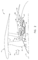
- Fig. 2 is a longitudinal cross-sectional view of an aircraft gas turbine engine like that depicted in Fig. 1 including a pulse detonation system having a first exemplary embodiment;
- Fig. 3 is an enlarged, partial longitudinal cross-sectional view of the pulse detonation system depicted in Fig. 2;
- Fig. 4 is a front view of the first rotatable ring member depicted in Figs. 2 and 3;
- Fig. 5 is a sectional view of a gas turbine engine like that depicted in Fig. 1 including a pulse detonation system having a second exemplary embodiment;
- Fig. 6 is an enlarged, partial longitudinal cross-sectional view of the pulse detonation system depicted in Fig. 5;
- Fig. 7 is a front view of the pulse detonation system depicted in Figs. 5 and 6;
- Fig. 8 is an enlarged, diagrammatic view of one of the detonation passages for the rotatable cylinders of the pulse detonation system depicted in Figs. 5-7;
- Fig. 9 is an enlarged, diagrammatic view of an alternate configuration for one of the detonation passages of the pulse detonation system depicted in Figs. 5-7; and,
- Fig. 10 is a partial sectional view of a second alternate configuration for one of the detonation passages of the pulse detonation system depicted in Figs. 5-7.
- Referring now to the drawings in detail, wherein identical numerals indicate the same elements throughout the figures, Fig. 1 schematically depicts a
gas turbine engine 10 utilized with aircraft having a longitudinal oraxial centerline axis 12 therethrough for reference purposes. It will be understood from the exemplary embodiment of Fig. 2 thatgas turbine engine 10 preferably includes anacelle 14 to assist in directing a flow of air (represented by arrow 16) through aninlet 18 to afan section 20 as is well known.Air flow 16 is then split downstream offan section 20 so that a first portion (represented by arrow 22) flows through anouter duct 24 and a second portion (represented by arrow 26) is provided to abooster compressor 28. A firstfan blade row 44 is preferably connected to afirst drive shaft 32. It will be understood thatbooster compressor 28 preferably includes at least a firstcompressor blade row 30, which preferably is stationary, and a secondcompressor blade row 34 connected to asecond drive shaft 33 and interdigitated with firstcompressor blade row 30. It will be appreciated that additional compressor blade rows 36 and 38 may also be connected tosecond drive shaft 33, with additional stationarycompressor blade rows second drive shafts pulse detonation system 46 in accordance with the present invention. - It will be understood that
pulse detonation system 46 will preferably initially power onlysecond drive shaft 33 during a first designated condition of gas turbine engine 10 (e.g., start-up of gas turbine engine 10). Becausesecond drive shaft 33 serves to cause the rotation ofbooster compressor 28, the much higher starting torque required byfan section 20 need not be extracted frompulse detonation system 46 during this first designated condition ofgas turbine engine 10. Oncebooster compressor 28 rotates at a predetermined rotational speed (i.e., a second designated operating condition of gas turbine engine 10),pulse detonation system 46 is then preferably utilized to powerfirst drive shaft 32 and cause rotation offan section 20, as well assecond drive shaft 33. By poweringsecond drive shaft 33 first, it will be appreciated thatbooster compressor 28 can supply the compressed air required bypulse detonation system 46 when the higher starting torque offan section 20 is required. Due to their coaxial relation, first andsecond drive shafts - While
pulse detonation system 46 may be configured in any of several different ways, it will generally be understood from Fig. 1 that a firstrotatable section 47 is provided for poweringsecond drive shaft 33 and a secondrotatable section 49 is provided for poweringfirst drive shaft 32. Firstrotatable section 47 will typically be located upstream of secondrotatable section 49, although the connection of first andsecond drive shafts pulse detonation system 46 may allow firstrotatable section 47 to be located downstream of secondrotatable section 49. - First
rotatable section 47 will generally include asingle stage 51, but may include additional stages depending upon the starting requirements ofbooster compressor 28 and the torque produced by each such stage of firstrotatable section 47. In light of the higher starting torque required byfan section 20, secondrotatable section 49 typically will have a plurality ofstages 53 incorporated therewith. By having a number ofstages 53, it will be appreciated that secondrotatable section 49 ofpulse detonation system 46 can be tuned to the requirements of operatinggas turbine engine 10 during any particular point in the engine cycle while maximizing the efficiency ofpulse detonation system 46. This is accomplished through the performance of detonation cycles within only those stages of second rotatable section 49 (and possibly only portions of such stages) that are needed to accomplish the desired torque infan section 20. - Although not required,
gas turbine engine 10 may further include aturbine 55 positioned aft of and in flow communication withpulse detonation system 46.Such turbine 55 would also preferably be connected tofirst drive shaft 32 so as to assist in poweringfan section 20.Turbine 55 would therefore preferably be driven by the gas products exitingpulse detonation system 46 and, particularly, secondrotatable section 49. Implementation ofturbine 55 withpulse detonation system 46 would serve to increase the efficiency ofgas turbine engine 10 instead of merely allowing the products from pulse detonation system to exit unused. - One exemplary embodiment for
pulse detonation system 46 is generally described in the '027 patent application, which is hereby incorporated by reference. - More specifically, as seen in Figs. 2-4, this configuration of
pulse detonation system 46 includes anair inlet duct 48 which is positioned so as to be in flow communication withbooster compressor 28.Air inlet duct 48 includes at least oneport 50 formed therein for permitting compressed air received frombooster compressor 28 to flow therethrough. In addition, afuel injector 52 is mounted toair inlet duct 48 in circumferentially spaced relation to eachport 50 and adevice 54 is mounted toair inlet duct 48 in circumferentially spaced relation to eachfuel injector 52 for initiating detonation waves. It will be appreciated thatinitiation device 54 may include, for example, an igniter (e.g., a high energy spark plug, a torch igniter having separate fuel and oxidizer, or a plasma jet igniter), a laser, or a shock focus device. - A first rotatable ring member 56 (corresponding to first
rotatable member 47 in Fig. 1) is preferably positioned in coaxial relation (with respect to centerline longitudinal axis 12) around an upstream portion ofair inlet duct 48. Firstrotatable ring member 56 includes at least onedetonation stage 58 disposed therein, although additional detonation stages may be provided therein in spaced axial relation downstream ofdetonation stage 58 depending upon the torque requirements ofbooster compressor 28. Similarly, a second rotatable ring member 57 (corresponding to secondrotatable member 49 in Fig. 1) is preferably positioned in coaxial relation around a downstream portion ofair inlet duct 48. Secondrotatable ring member 57 preferably includes a plurality of detonation stages 59 disposed therein in spaced axial relation due to the high starting torque requirements offan section 20. - Each detonation stage of first
rotatable ring member 56 and secondrotatable ring member 57 preferably has a plurality of circumferentially spaceddetonation ducts inner surface 74 of firstrotatable ring member 56 and aninner surface 75 of secondrotatable ring member 57 in a distinct radial plane. It is also preferred that first and secondrotatable ring members adjacent detonation duct 66 and eachadjacent detonation duct 67 so as to reduce weight, thereby givingdetonation ducts 66 and 67 a tube-like appearance. In order to provide added stability, various connections may be provided betweenadjacent detonation ducts 66 and betweenadjacent detonation ducts 67. An alternative configuration may involve a ring member having tubes attached to an outer surface thereof. - It will be understood that while
detonation ducts detonation stage longitudinal centerline axis 12, it is preferred thatdetonation ducts axis 68 substantially perpendicular tolongitudinal centerline axis 12. In this way, the flow of combustion gases exitingdetonation ducts detonation duct 66 extends from a first end orinlet 72 adjacent aninner surface 74 of firstrotatable ring member 56 to a second end oroutlet 76 adjacent anouter surface 78 of firstrotatable ring member 56, while eachdetonation duct 67 extends from a first end orinlet 73 adjacent aninner surface 75 of secondrotatable ring member 57 to a second end or outlet 77 adjacent anouter surface 79 of secondrotatable ring member 57. It will be appreciated thatinlets detonation ducts inner surfaces rotatable ring members air inlet duct 48. Nevertheless, each ofdetonation ducts inlets outlets 76 and 77. Each ofdetonation ducts detonation ducts -
Detonation ducts rotatable ring member longitudinal centerline axis 12. While this configuration may ease manufacture and maintenance, it is contemplated that staggering ofsuch detonation ducts pulse detonation system 46. - Regardless of the configuration utilized for
detonation ducts detonation ducts air port 50,fuel injector 52, anddetonation initiation device 54 in a predetermined timing and sequence so that a detonation wave is produced therein. This is also evidenced by the direction of rotation for firstrotatable ring member 56, as represented byarrow 81 in Fig. 4. Combustion gases then follow each detonation wave, the momentum of which produces a force that creates a torque on first and secondrotatable ring members detonation ducts ring members detonation ducts 66 and 67), however, it is preferred that firstrotatable ring member 56 rotate at a predetermined speed. This is caused by the compressed air being supplied todetonation ducts air port 50. It is also preferred thatdetonation ducts air inlet duct 48 while detonation (and the consequent pressure rise) occurs therein. In this way,booster compressor 28 andfan section 20 are isolated from the high pressure therein and thereby avoids stall or surge. - It will be appreciated that compressed air will preferably be supplied in each
detonation duct successive detonation duct pulse detonation system 46 and whether a buffer or delay is desired between detonations. Accordingly, devices (not shown) are preferably provided to control the supply of fuel through a manifold tofuel injectors 52 and the initiation of detonation waves indetonation ducts 66 byinitiation device 54. - In order to prevent compressed air or fuel from leaking between
adjacent detonation ducts air inlet duct 48 andinner surfaces rotatable ring members - It is also preferred that a plurality of detonation cycles occur in each
detonation duct rotatable ring members additional air port 90 circumferentially spaced frominitiation device 54, anadditional fuel injector 92 circumferentially spaced fromair port 90, and anadditional device 94 circumferentially spaced fromfuel injector 92 for initiating detonation waves are provided in or mounted toair inlet duct 48. It will be appreciated that a designatedcircumferential spacing 96 is provided betweenadditional air port 90 andinitiation device 94 so as to provide substantial symmetry between detonation sequences in any detonation stage. Of course, this will be dependent upon the overall number of detonation sequences (with the associated air port, fuel injector and ignition device) provided in a given detonation stage. - As seen in Fig. 2 with respect to
gas turbine engine 10, anozzle plenum 98 is preferably positioned with respect to first andsecond ring members 56 and 57 (andoutlets 76 and 77 ofdetonation ducts 66 and 67) so as to be in flow communication with the combustion gases exiting therefrom. In this way, additional thrust is produced through anexit nozzle 100. Further, at least one turbine stage (not shown) may be positioned in flow communication withnozzle plenum 98. Such turbine stage may be connected to driveshaft 32 or another drive shaft so as to produce additional thrust or work. - A second embodiment for the pulse detonation system is depicted schematically in Fig. 5. More specifically, it will be seen that a
gas turbine engine 110 has alongitudinal centerline axis 112 therethrough and preferably includes anacelle 114 to assist in directing a flow of air (represented by arrow 116) through aninlet 118 to afan section 120.Air flow 116 is then split downstream offan section 120 so that a first portion (represented by arrow 122) flows through anouter duct 124 and a second portion (represented by arrow 126) is provided to abooster compressor 128. A firstfan blade row 144 is preferably connected to afirst drive shaft 132. It will be understood thatbooster compressor 128 preferably includes at least one stationary compressor blade row (seecompressor blade rows compressor blade rows 34, 36 and 38 of booster compressor 28) connected to asecond drive shaft 133 and interdigitated with the stationary compressor blade row(s). First andsecond drive shafts pulse detonation system 146. - As further seen in Figs. 5 and 6,
pulse detonation system 146 preferably includes a first rotatablecylindrical member 147 and a secondrotatable member 149 which are coaxially oriented aboutlongitudinal centerline axis 112. In the configuration shown, first rotatablecylindrical member 147 is located so as to be in a somewhat upstream axial position as compared to secondrotatable member 149, as well as a somewhat outer radial position with respect to such secondrotatable member 149. It will be appreciated that first rotatablecylindrical member 147 is preferably connected tosecond drive shaft 133 so as topower booster compressor 128 while second rotatablecylindrical member 149 is preferably connected tofirst drive shaft 132 so as topower fan section 120. In this way, second rotatablecylindrical member 149 is utilized to drive the component requiring the most torque. - It will be understood that
pulse detonation system 146 will preferably initially power onlysecond drive shaft 133 during a first designated condition of gas turbine engine 110 (e.g., start-up of gas turbine engine 110). Becausesecond drive shaft 133 serves to cause the rotation ofbooster compressor 128, the much higher starting torque required byfan section 120 need not be extracted frompulse detonation system 146 during this first designated condition ofgas turbine engine 110. Oncebooster compressor 128 rotates at a predetermined rotational speed (i.e., a second designated operating condition of gas turbine engine 110),pulse detonation system 146 is then preferably utilized to powerfirst drive shaft 132 and cause rotation offan section 120, as well assecond drive shaft 133 andbooster compressor 128. By poweringsecond drive shaft 133 first, it will be appreciated thatbooster compressor 128 can supply the compressed air required bypulse detonation system 146 when the higher starting torque offan section 120 is required. Due to their coaxial relation, first andsecond drive shafts - It will be understood that first and second rotatable
cylindrical members gas turbine engine 110 preferably have the basic configuration of that shown and described inU.S. patent application 10/803,293 (entitled "Rotary Pulse Detonation System With Aerodynamic Detonation Passages For Use In A Gas Turbine Engine,"),U.S. Patent application 10/422,314 (entitled "Rotating Pulse Detonation System For A Gas Turbine Engine"), or some combination thereof. Each of these applications is hereby incorporated by reference. Accordingly, Fig. 6 depicts first rotatablecylindrical member 147 as including aforward surface 148, anaft surface 150, and an outercircumferential surface 155. It will be noted that first rotatablecylindrical member 147 includes an integral middle portion which is connected tosecond drive shaft 133, but it will be understood that at least oneseparate disk member 156 may be provided to connect first rotatablecylindrical member 147 withdrive shaft 133. - Similarly, second rotatable
cylindrical member 149 ofpulse detonation system 146 preferably includes aforward surface 157, anaft surface 159, and an outercircumferential surface 160. The direction of rotation for second rotatablecylindrical member 149 is preferably the same as for first rotatablecylindrical member 147. As depicted, second rotatablecylindrical member 149 preferably includes at least oneseparate disk member 161 to connect second rotatablecylindrical member 149 withdrive shaft 132. It will be understood, however, that second rotatablecylindrical member 149 may include an integral middle portion which is connected tofirst drive shaft 132. - In the instance when first and/or second rotatable
cylindrical members respective disk members dovetail members 162 which mate with a like number ofdovetail slots 163, respectively, formed insuch disk member 156. It will be appreciated from Fig. 7 that first rotatablecylindrical member 147 is preferably formed by a plurality ofannular segments 164 which includedovetail members 162. Suchannular members 164 generally will include at least onedetonation passage 166 therein depending on the circumferential spacing between detonation passages and the arcuate length ofannular segments 164. It will be recognized, however, that not everyannular segment 164 need include such a detonation passage, such as with respect to the circumferential spacing between groups of ports as described herein. In any event, assembly and disassembly of first rotatablecylindrical member 147 is simplified, with maintenance or replacement of only affected areas being required. - First and second rotatable
cylindrical members detonation passages cylindrical member 147, eachdetonation passage 166 is preferably formed to include a leadingportion 168 positioned at an upstream end adjacentforward surface 148, a trailingportion 170 positioned at a downstream end adjacentaft surface 150, and amiddle portion 172 connecting leadingportion 168 with trailingportion 170. It will be appreciated that aphantom line 174 is depicted to generally define the transition between leadingportion 168 andmiddle portion 172, while aphantom line 176 is similarly depicted to generally define the transition betweenmiddle portion 172 and trailingportion 170. Of course, it will be understood thatdetonation passages 167 of second rotatablecylindrical member 149 may have the same configuration as set forth fordetonation passages 166 of first rotatablecylindrical member 147. - It will further be appreciated from the '293 patent application that
detonation passages cylindrical members portion 168 is such that acenterline 178 is substantially alignable vectorally with the flow emanating from a group of ports in astator 180 as described more specifically herein. It will be appreciated, however, that the optimal angular orientation of leadingportions 168 fordetonation passages 166 is preferably determined by an analysis of the velocity vectors for inlet air and fuel supplied by the group of ports in light of the rotational velocity of first rotatablecylindrical member 147 over a range of operating conditions for the engine. - It will further be noted that a
centerline 182 for trailingportion 170 of eachdetonation passage 166 is also preferably oriented at a designated angle so as to permit the combustion gases to exitaft surface 150 of first rotatablecylindrical member 147 in a manner to create a torque which causes first rotatablecylindrical member 147 to rotate. As evidenced by the figures,detonation passages 166 are preferably symmetrical so that leadingportion 168 and trailingportion 170 are oriented in opposite directions at designated angles having substantially the same magnitude. It is understood, however, that the magnitude of such respective angles may be different and need not be substantially the same. - Each
detonation passage detonation passages portion 170 ofsuch detonation passages 166 may have a diverging cross-section so as to have an increasing diameter fromdiameter 184 atphantom line 176 to amaximum diameter 186 ataft surface 150 of first rotatablecylindrical member 147. It will also be noted that leadingportion 168 may have a converging cross-sectional area so that itsdiameter 188 atforward surface 148 of first rotatablecylindrical member 147 is greater thandiameter 190 atphantom line 174. In this way, flow through and pressure withindetonation passages 166 may be controlled for their desirable effects. - It will further be seen that
middle portion 172 of eachdetonation passage 166 is configured to have a substantially constantly changing slope within its specified plane as it connects leading and trailingportions middle portion 172 is configured so that acenterline 192 therethrough is aligned withcenterline 178 of leadingportion 168 at a first end. Similarly,middle portion 172 is configured so thatcenterline 192 is aligned withcenterline 182 of trailingportion 170 at a second end. Since leadingportion 168 and trailingportion 170 are oriented in opposite directions,middle portion 172 will include a midpoint (defined by a phantom line 194) which transitionsmiddle portion 172 from one direction to another (i.e., where the slope thereof is zero). Depending on the particular orientations of leadingportion 168 and trailingportion 170 ofdetonation passages 166,centerline 192 at any given location will be oriented at a positive or negative angle. The range of slope formiddle portion 172 will likewise depend upon the respective designated angles of leadingportion 168 and trailingportion 170, respectively. - By configuring
middle portion 172 in the manner described, it will be understood that changes in pressure occur therein so that the combustion gases formed by the detonation process in eachdetonation passage cylindrical members cylindrical members middle portion 172, as well as the change in direction of leadingportion 168 and trailingportion 170. The configuration ofdetonation passages detonation passages - It is further preferred that
detonation passages cylindrical members detonation passages cylindrical members portion 168 and trailingportion 170, respectively, and a diameter of first and second rotatablecylindrical members annular segments 164 be connected to first rotatable cylindrical member 147 (e.g., viadovetail slots 163 formed in disk member 156), where eachannular segment 164 typically includes at least onedetonation passage 166 formed therein. Of course,detonation passages -
Pulse detonation system 146 further includes first andsecond stators forward surfaces cylindrical members drive shafts stator second seal plates forward surfaces cylindrical members rear surfaces second stators - As seen in Fig. 7 with respect to first rotatable
cylindrical member 147,first stator 180 further includes at least one group ofports 206 formed therein. It will be understood that eachport group 206 has anair port 208 in flow communication with a source of compressed air (e.g., compressed air flow 130 from booster compressor 128), afuel port 210 in flow communication with a fuel source, and aport 212 having a device (not shown) associated therewith for initiating a detonation indetonation passages 166. It is contemplated that exemplary initiation devices may include an igniter (e.g., a high energy spark plug, a torch igniter having separate fuel and oxidizer, or a plasma jet igniter), a laser, or a shock focus device. The initiation device may be activated whenport 212 is in communication with eachdetonation passage 166 so as to assist in producing a detonation wave in alldetonation passages 166 or in accordance with a predetermined delay so that onlycertain detonation passages 166 are utilized for this purpose. A control device (not shown) is preferably provided to control the initiation of detonations withindetonation passages 166. Although not particularly shown by a separate figure, it will be understood thatsecond stator 196 associated with second rotatablecylindrical member 149 is preferably configured in like manner to that described forfirst stator 180. - It will be understood that detonation cycles are performed in
detonation passages detonation passages middle portion 172 and exit aftsurfaces cylindrical members cylindrical members - It will be appreciated that prior to the occurrence of any detonation cycles within
detonation passages cylindrical members detonation passages air ports 208 at a relatively higher pressure than the pressure at which air is discharged fromdetonation passages cylindrical members 147 and 179 are achieved, fuel is then supplied todetonation passages - It will be appreciated that a plurality of
port groups 206 may be provided in first andsecond stators detonation passage cylindrical members Such port groups 206 are preferably spaced symmetrically around first andsecond stators port groups 206 may be equivalent to the number ofdetonation passages cylindrical members port group 206, as well as between each individual port thereof. Such circumferential spacing may be equivalent to areplaceable segment 164 which does not include a detonation passage therethrough. - Another aspect of
pulse detonation system 146 is the manner in which fuel is supplied to fuelports 210 for injection intodetonation passages second fuel manifolds second stators 180 and 196 (see Fig. 5).Fuel manifolds fuel ports 210 at a second end so that fuel is supplied thereto as part of the detonation cycle indetonation passages device 220 is provided to control the injection of fuel fromfuel manifolds - It will further be understood that the configuration of
detonation passages cylindrical member detonation passage 266 and described in the '314 patent application,detonation passages 266 of first rotatablecylindrical member 147 may be substantially linear and have alongitudinal axis 268 extending through at least a portion thereof at a circumferential angle tolongitudinal centerline axis 112. Such angle is preferably an acute angle which preferably is within a range of approximately 20-85° and optimally within a range of approximately 40-75°. It will be appreciated, however, that the optimal angular orientation ofdetonation passages 266 is preferably determined by an analysis of the velocity vectors for inlet air supplied byair port 208 and fuel fromfuel port 210 in light of the rotational velocity of first rotatablecylindrical member 147 over a range of operating conditions for the engine. Accordingly,detonation passages 266 have an eccentric orientation with respect tolongitudinal centerline axis 112. It will be understood thatdetonation passages 266 may also be oriented at a radial angle tolongitudinal centerline axis 112 so long as the circumferential angle is maintained. -
Detonation passages 266 may be substantially non-linear so long as at least a portion thereof maintains the eccentric orientation with respect tolongitudinal centerline axis 112. In this regard, it will be seen from Fig. 10 thatdetonation passage 266 may include afirst portion 270 including alongitudinal axis 272 extending therethrough oriented substantially parallel tolongitudinal centerline axis 112 and asecond portion 274 in flow communication withfirst portion 270 including alongitudinal axis 275 extending therethrough which is oriented at a predetermined circumferential angle tolongitudinal axis 272. Accordingly,second portion 274 ofdetonation passages 266 are likewise oriented at a designated angle tolongitudinal centerline axis 112 and is preferably in a range of approximately 20-85° or optimally in a range of approximately 40-75° as described above. Although not shown,detonation passages 266 may be curved so as to obtain a similar eccentric orientation with respect tolongitudinal centerline axis 112. It will be understood that detonation passages having an alternative configuration like that described fordetonation passages 266 may be employed instead of the configuration fordetonation passages 167 in second rotatablecylindrical member 149. - In accordance with the description of
pulse detonation system 46 forgas turbine engine 10, it will be appreciated that a method of independently powering separate drive shafts in a gas turbine engine is also associated therewith. Such method, with respect togas turbine engine 10, preferably includes the step of providing a first rotatable member (e.g., first rotatable ring member 56) with a plurality of detonation areas associated therewith (i.e., at least onestage 58 of circumferentially spaced detonation ducts 66). Another step of the method is connecting first rotatable member to asecond drive shaft 33. The next step preferably includes providing a second rotatable member (e.g., second rotatable ring member 57) with a plurality of detonation areas associated therewith and connecting such second rotatable member to afirst drive shaft 32. Thereafter, the method includes the step of producing a torque on the first rotatable member via the performance of pulse detonation cycles in the detonation areas thereof during a first designated condition ofgas turbine engine 10. An additional step is producing a torque on the second rotatable member via the performance of pulse detonation cycles in the detonation areas thereof during a second designated condition ofgas turbine engine 10. - In this way, a detonation cycle is performed in each
detonation duct ring members drive shafts detonation ducts detonation ducts detonation ducts detonation ducts air port 50 inair inlet duct 48, afuel injector 52 in circumferentially spaced relation toair port 50, and adevice 54 in circumferentially spaced relation tofuel injector 52 for initiating a detonation wave. - With respect to
pulse detonation system 146 ofgas turbine engine 110, a similar method of independently powering separate drive shafts in a gas turbine engine is also associated therewith. Such method, with respect togas turbine engine 110, preferably includes the step of providing a first rotatable member (e.g., first rotatable cylindrical member 147) with a plurality of detonation areas associated therewith (i.e., at least one stage of circumferentially spaced detonation passages 166). Another step of the method is connecting first rotatablecylindrical member 147 to asecond drive shaft 133. The next steps preferably include providing a second rotatable member (e.g., second rotatable cylindrical member 149) with a plurality of detonation areas associated therewith (i.e., at least one stage of circumferentially spaced detonation passages 167) and connecting such second rotatablecylindrical member 149 tofirst drive shaft 132. Thereafter, the method includes the step of producing a torque on first rotatablecylindrical member 147 via the performance of pulse detonation cycles in the detonation areas thereof during a first designated condition ofgas turbine engine 110. An additional step is producing a torque on the second rotatablecylindrical member 149 via the performance of pulse detonation cycles in the detonation areas thereof during a second designated condition ofgas turbine engine 110. - In this way, a detonation cycle is performed in each
detonation passage cylindrical members second drive shafts detonation passages detonation passages detonation passages detonation passages air port 208 in first andsecond stators fuel injector 210 in circumferentially spaced relation toair port 208, and a device withininitiation port 212 in circumferentially spaced relation tofuel injector 210 for initiating a detonation wave.
Claims (10)
- A gas turbine engine (10, 110) having a longitudinal centerline axis (12, 112) therethrough, comprising:(a) a fan section (20, 120) at a forward end of said gas turbine engine (10,110)
including at least a first fan blade row (44, 144) connected to a first drive
shaft (32, 132);(b) a booster compressor (28, 128) positioned downstream of said fan section
(20, 120), said booster compressor (28, 128) including a first compressor
blade row (30) and a second compressor blade row (34) connected to a
second drive shaft (33, 133) and interdigitated with said first compressor
blade row (30); and,(c) a pulse detonation system (46, 146) powering said first and second drive
shafts (32, 33, 132, 133). - The gas turbine engine (10, 110) of claim 1, wherein said pulse detonation system (46, 146) powers only said second drive shaft (33, 133) during a first designated condition of said gas turbine engine (10, 110).
- The gas turbine engine (10, 110) of claim 1, wherein said pulse detonation system (46, 146) powers both said first drive shaft (32, 132) and said second drive shaft (33, 133) during a second designated condition of said gas turbine engine (10, 110).
- The gas turbine engine (10, 110) of claim 1, wherein said first and second drive shafts (32, 33, 132, 133) are powered independently of each other by said pulse detonation system (46, 146).
- The gas turbine engine (10) of claim 1, said pulse detonation system (46) further comprising a first rotatable section (47) for powering said second drive shaft (33).
- The gas turbine engine (10) of claim 5, said pulse detonation system (46) further comprising a second rotatable section (49) for powering said first drive shaft (32).
- The gas turbine engine (10) of claim 1, further comprising a turbine (55) positioned aft of and in flow communication with said pulse detonation system (46), wherein said turbine (55) is also utilized to power said first drive shaft (32).
- The gas turbine engine (10) of claim 1, said pulse detonation system (46) further comprising:(a) an air inlet duct (48) in flow communication with said booster compressor
(28), said air inlet duct (48) including at least one port (50) formed therein
for permitting compressed air to flow therethrough;(b) a fuel injector (52) mounted to said air inlet duct (48) in circumferentially
spaced relation to each said port (50);(c) a device (54) mounted to said air inlet duct (48) in circumferentially spaced
relation to each said fuel injector (52) for initiating a detonation wave;(d) a first rotatable ring member (56) positioned in coaxial relation around a
first portion of said air inlet duct (48), said first ring member (56)
including at least one stage (58) of detonation ducts (66) disposed therein,
wherein said first ring member (56) is connected to said second drive
shaft (33); and,(e) a second rotatable ring member (57) positioned in coaxial relation around a
second portion of said air inlet duct (48), said second ring member (57)
including at least one stage (59) of detonation ducts (67) disposed therein,
wherein said second ring member (57) is connected to said first drive
shaft (32);
wherein detonation waves are produced in said detonation stage (58) of said first rotatable ring member (56) during said first designated condition of said gas turbine engine (10) so that combustion gases following each said detonation wave create a torque which causes said first ring member (56) to rotate and power said second drive shaft (33). - The gas turbine engine (110) of claim 1, said pulse detonation system (146) further comprising:(a) a first rotatable cylindrical member (147) having a forward surface (148),
an aft surface (148), and an outer circumferential surface (155), said first
rotatable cylindrical member (147) including at least one stage of
circumferentially spaced detonation passages (166) disposed therethrough,
wherein said first rotatable cylindrical member (147) is connected to said
second drive shaft (133);(b) a second rotatable cylindrical member (149) located adjacent said first
rotatable cylindrical member (147), said second rotatable cylindrical
member (149) having a forward surface (157), an aft surface (159), and an
outer circumferential surface (160) and including at least one stage of
circumferentially spaced detonation passages (167) disposed therethrough,
wherein said second rotatable cylindrical member (149) is connected to
said first drive shaft (132);(c) a first stator (180) configured in spaced arrangement with said first
rotatable cylindrical member (147), said first stator (180) including at
least one group of ports (206) formed therein alignable with said
detonation passages (166) as said first cylindrical member (147) rotates;
and,(d) a second stator (196) configured in spaced arrangement with said second
rotatable cylindrical member (149), said second stator (196) including at
least one group of ports (206) formed therein alignable with said
detonation passages (167) as said second cylindrical member (149) rotates;
wherein detonation cycles are performed in said detonation stage of said first rotatable cylindrical member (147) during a first designated condition of said gas turbine engine (110) to create a torque which causes said first rotatable cylindrical member (147) to rotate and power said second drive shaft (133). - The gas turbine engine (110) of claim 9, said detonation passages (166, 167) in said first and second rotatable cylindrical members (147, 149) further comprising:(a) a leading portion (168) positioned adjacent said forward surface (148, 157)
of said cylindrical member (147, 149), said leading portion (168) having a
centerline (178) therethrough oriented at a designated angle to an axis
extending substantially parallel to said longitudinal centerline axis (112)
within a specified plane;(b) a trailing portion (170) positioned adjacent said aft surface (150, 159) of
said cylindrical member (147, 149), said trailing portion (170) having a
centerline (182) therethrough oriented at a designated angle to said axis
within said specified plane; and,(c) a middle portion (172) connecting said leading and trailing portions (168, 170), said middle portion (172) having a centerline (192) therethrough with a substantially constantly changing slope in said specified plane.
Applications Claiming Priority (1)
| Application Number | Priority Date | Filing Date | Title |
|---|---|---|---|
| US10/932,169 US7328570B2 (en) | 2004-09-01 | 2004-09-01 | Pulse detonation system for a gas turbine engine having multiple spools |
Publications (2)
| Publication Number | Publication Date |
|---|---|
| EP1632673A1 true EP1632673A1 (en) | 2006-03-08 |
| EP1632673B1 EP1632673B1 (en) | 2007-07-25 |
Family
ID=35453572
Family Applications (1)
| Application Number | Title | Priority Date | Filing Date |
|---|---|---|---|
| EP05255345A Expired - Lifetime EP1632673B1 (en) | 2004-09-01 | 2005-09-01 | Pulse detonation system for a gas turbine engine having multiple spools |
Country Status (4)
| Country | Link |
|---|---|
| US (1) | US7328570B2 (en) |
| EP (1) | EP1632673B1 (en) |
| CA (1) | CA2516751C (en) |
| DE (1) | DE602005001738T2 (en) |
Families Citing this family (12)
| Publication number | Priority date | Publication date | Assignee | Title |
|---|---|---|---|---|
| US7895820B2 (en) * | 2005-11-16 | 2011-03-01 | Techland Research, Inc. | Seal for pulse detonation engine |
| US7685806B2 (en) * | 2005-12-29 | 2010-03-30 | General Electric Company | Method and apparatus for supersonic and shock noise reduction in aircraft engines using pneumatic corrugations |
| US7752835B2 (en) * | 2006-06-01 | 2010-07-13 | United Technologies Corporation | Pulsed combustion engine |
| WO2008070210A2 (en) * | 2006-06-15 | 2008-06-12 | Indiana University Research And Technology Corporation | Pilot fuel injection for a wave rotor engine |
| US20090266047A1 (en) * | 2007-11-15 | 2009-10-29 | General Electric Company | Multi-tube, can-annular pulse detonation combustor based engine with tangentially and longitudinally angled pulse detonation combustors |
| US8616005B1 (en) | 2009-09-09 | 2013-12-31 | Dennis James Cousino, Sr. | Method and apparatus for boosting gas turbine engine performance |
| US9212626B2 (en) * | 2013-07-10 | 2015-12-15 | Derrick T. Miller, Jr. | Engine propulsion system |
| US9709069B2 (en) | 2013-10-22 | 2017-07-18 | Dayspring Church Of God Apostolic | Hybrid drive engine |
| EP2868864A1 (en) * | 2013-11-04 | 2015-05-06 | Institut von Karman de Dynamique des Fluides, AISBL | Axial fluid machine and method for power extraction |
| US10526965B2 (en) * | 2016-04-29 | 2020-01-07 | Rolls-Royce Corporation | Ignition system for constant volume combustor |
| US11852077B2 (en) * | 2021-04-15 | 2023-12-26 | Rtx Corporation | Regenerative cooling and adjustable throat for rotating detonation engine |
| CN114607525B (en) * | 2022-04-02 | 2022-07-19 | 中北大学 | Hydrogen fuel rotary ramjet turbofan engine |
Citations (4)
| Publication number | Priority date | Publication date | Assignee | Title |
|---|---|---|---|---|
| EP1435440A1 (en) * | 2002-12-30 | 2004-07-07 | United Technologies Corporation | Pulsed combustion engine |
| EP1435448A1 (en) * | 2002-12-30 | 2004-07-07 | United Technologies Corporation | Pulsed combustion turbine engine |
| US20050028531A1 (en) | 2003-04-24 | 2005-02-10 | Venkataramani Kattalaicheri Srinivasan | Rotating pulse detonation system for a gas turbine engine |
| US20060207261A1 (en) | 2004-03-18 | 2006-09-21 | Venkataramani Kattalaicheri S | Rotary pulse detonation system with aerodynamic detonation passages for use in a gas turbine engine |
Family Cites Families (8)
| Publication number | Priority date | Publication date | Assignee | Title |
|---|---|---|---|---|
| US2640314A (en) * | 1949-12-16 | 1953-06-02 | William E Abel | Disk valve pulse jet engine |
| US5901550A (en) * | 1993-04-14 | 1999-05-11 | Adroit Systems, Inc. | Liquid fueled pulse detonation engine with controller and inlet and exit valves |
| US5345758A (en) * | 1993-04-14 | 1994-09-13 | Adroit Systems, Inc. | Rotary valve multiple combustor pulse detonation engine |
| US6349538B1 (en) * | 2000-06-13 | 2002-02-26 | Lockheed Martin Corporation | Annular liquid fueled pulse detonation engine |
| US6505462B2 (en) * | 2001-03-29 | 2003-01-14 | General Electric Company | Rotary valve for pulse detonation engines |
| US7047724B2 (en) * | 2002-12-30 | 2006-05-23 | United Technologies Corporation | Combustion ignition |
| US6901738B2 (en) * | 2003-06-26 | 2005-06-07 | United Technologies Corporation | Pulsed combustion turbine engine |
| US6904750B2 (en) * | 2003-04-18 | 2005-06-14 | General Electric Company | Integral pulse detonation system for a gas turbine engine |
-
2004
- 2004-09-01 US US10/932,169 patent/US7328570B2/en not_active Expired - Fee Related
-
2005
- 2005-08-18 CA CA2516751A patent/CA2516751C/en not_active Expired - Fee Related
- 2005-09-01 EP EP05255345A patent/EP1632673B1/en not_active Expired - Lifetime
- 2005-09-01 DE DE602005001738T patent/DE602005001738T2/en not_active Expired - Lifetime
Patent Citations (4)
| Publication number | Priority date | Publication date | Assignee | Title |
|---|---|---|---|---|
| EP1435440A1 (en) * | 2002-12-30 | 2004-07-07 | United Technologies Corporation | Pulsed combustion engine |
| EP1435448A1 (en) * | 2002-12-30 | 2004-07-07 | United Technologies Corporation | Pulsed combustion turbine engine |
| US20050028531A1 (en) | 2003-04-24 | 2005-02-10 | Venkataramani Kattalaicheri Srinivasan | Rotating pulse detonation system for a gas turbine engine |
| US20060207261A1 (en) | 2004-03-18 | 2006-09-21 | Venkataramani Kattalaicheri S | Rotary pulse detonation system with aerodynamic detonation passages for use in a gas turbine engine |
Also Published As
| Publication number | Publication date |
|---|---|
| US20060042228A1 (en) | 2006-03-02 |
| CA2516751C (en) | 2011-06-07 |
| US7328570B2 (en) | 2008-02-12 |
| DE602005001738D1 (en) | 2007-09-06 |
| CA2516751A1 (en) | 2006-03-01 |
| EP1632673B1 (en) | 2007-07-25 |
| DE602005001738T2 (en) | 2008-04-10 |
Similar Documents
| Publication | Publication Date | Title |
|---|---|---|
| EP1455065B1 (en) | Pulse detonation system for a gas turbine engine | |
| EP1427926B1 (en) | Rotary heat engine | |
| US6931858B2 (en) | Rotating pulse detonation system for a gas turbine engine | |
| EP1435448B1 (en) | Pulsed combustion turbine engine | |
| US6889505B2 (en) | Pulse detonation system for a gas turbine engine | |
| CN108930557B (en) | Method and system for auxiliary guide vanes at the leading edge of compressor guide vanes | |
| US9062609B2 (en) | Symmetric fuel injection for turbine combustor | |
| US20050000205A1 (en) | Pulsed combustion engine | |
| US20120131902A1 (en) | Aft fan adaptive cycle engine | |
| US20180231256A1 (en) | Rotating Detonation Combustor | |
| US20180356099A1 (en) | Bulk swirl rotating detonation propulsion system | |
| EP1632673B1 (en) | Pulse detonation system for a gas turbine engine having multiple spools | |
| US20180355792A1 (en) | Annular throats rotating detonation combustor | |
| EP2791489B1 (en) | Radial inflow gas turbine engine with advanced transition duct | |
| US7124573B2 (en) | Rotary pulse detonation system with aerodynamic detonation passages for use in a gas turbine engine | |
| WO2005005805A2 (en) | Turbineless jet engine | |
| US6904750B2 (en) | Integral pulse detonation system for a gas turbine engine | |
| EP1435440B1 (en) | Pulsed combustion engine | |
| EP4276357B1 (en) | A combustion system |
Legal Events
| Date | Code | Title | Description |
|---|---|---|---|
| PUAI | Public reference made under article 153(3) epc to a published international application that has entered the european phase |
Free format text: ORIGINAL CODE: 0009012 |
|
| AK | Designated contracting states |
Kind code of ref document: A1 Designated state(s): AT BE BG CH CY CZ DE DK EE ES FI FR GB GR HU IE IS IT LI LT LU LV MC NL PL PT RO SE SI SK TR |
|
| AX | Request for extension of the european patent |
Extension state: AL BA HR MK YU |
|
| 17P | Request for examination filed |
Effective date: 20060908 |
|
| AKX | Designation fees paid |
Designated state(s): DE FR GB IT SE |
|
| GRAP | Despatch of communication of intention to grant a patent |
Free format text: ORIGINAL CODE: EPIDOSNIGR1 |
|
| GRAC | Information related to communication of intention to grant a patent modified |
Free format text: ORIGINAL CODE: EPIDOSCIGR1 |
|
| GRAS | Grant fee paid |
Free format text: ORIGINAL CODE: EPIDOSNIGR3 |
|
| GRAA | (expected) grant |
Free format text: ORIGINAL CODE: 0009210 |
|
| AK | Designated contracting states |
Kind code of ref document: B1 Designated state(s): DE FR GB IT SE |
|
| REG | Reference to a national code |
Ref country code: GB Ref legal event code: FG4D |
|
| REF | Corresponds to: |
Ref document number: 602005001738 Country of ref document: DE Date of ref document: 20070906 Kind code of ref document: P |
|
| REG | Reference to a national code |
Ref country code: SE Ref legal event code: TRGR |
|
| ET | Fr: translation filed | ||
| PLBE | No opposition filed within time limit |
Free format text: ORIGINAL CODE: 0009261 |
|
| STAA | Information on the status of an ep patent application or granted ep patent |
Free format text: STATUS: NO OPPOSITION FILED WITHIN TIME LIMIT |
|
| 26N | No opposition filed |
Effective date: 20080428 |
|
| REG | Reference to a national code |
Ref country code: FR Ref legal event code: PLFP Year of fee payment: 11 |
|
| PGFP | Annual fee paid to national office [announced via postgrant information from national office to epo] |
Ref country code: GB Payment date: 20150928 Year of fee payment: 11 |
|
| PGFP | Annual fee paid to national office [announced via postgrant information from national office to epo] |
Ref country code: SE Payment date: 20150929 Year of fee payment: 11 Ref country code: FR Payment date: 20150917 Year of fee payment: 11 |
|
| PGFP | Annual fee paid to national office [announced via postgrant information from national office to epo] |
Ref country code: IT Payment date: 20150923 Year of fee payment: 11 |
|
| PGFP | Annual fee paid to national office [announced via postgrant information from national office to epo] |
Ref country code: DE Payment date: 20150929 Year of fee payment: 11 |
|
| REG | Reference to a national code |
Ref country code: DE Ref legal event code: R119 Ref document number: 602005001738 Country of ref document: DE |
|
| PG25 | Lapsed in a contracting state [announced via postgrant information from national office to epo] |
Ref country code: SE Free format text: LAPSE BECAUSE OF NON-PAYMENT OF DUE FEES Effective date: 20160902 |
|
| REG | Reference to a national code |
Ref country code: SE Ref legal event code: EUG |
|
| GBPC | Gb: european patent ceased through non-payment of renewal fee |
Effective date: 20160901 |
|
| REG | Reference to a national code |
Ref country code: FR Ref legal event code: ST Effective date: 20170531 |
|
| PG25 | Lapsed in a contracting state [announced via postgrant information from national office to epo] |
Ref country code: FR Free format text: LAPSE BECAUSE OF NON-PAYMENT OF DUE FEES Effective date: 20160930 Ref country code: DE Free format text: LAPSE BECAUSE OF NON-PAYMENT OF DUE FEES Effective date: 20170401 Ref country code: GB Free format text: LAPSE BECAUSE OF NON-PAYMENT OF DUE FEES Effective date: 20160901 |
|
| PG25 | Lapsed in a contracting state [announced via postgrant information from national office to epo] |
Ref country code: IT Free format text: LAPSE BECAUSE OF NON-PAYMENT OF DUE FEES Effective date: 20160901 |