EP1632653A1 - Cooling water passage in engine cylinder head - Google Patents
Cooling water passage in engine cylinder head Download PDFInfo
- Publication number
- EP1632653A1 EP1632653A1 EP04021096A EP04021096A EP1632653A1 EP 1632653 A1 EP1632653 A1 EP 1632653A1 EP 04021096 A EP04021096 A EP 04021096A EP 04021096 A EP04021096 A EP 04021096A EP 1632653 A1 EP1632653 A1 EP 1632653A1
- Authority
- EP
- European Patent Office
- Prior art keywords
- cooling water
- cylinder head
- passage
- engine
- cooling
- Prior art date
- Legal status (The legal status is an assumption and is not a legal conclusion. Google has not performed a legal analysis and makes no representation as to the accuracy of the status listed.)
- Granted
Links
Images


Classifications
-
- F—MECHANICAL ENGINEERING; LIGHTING; HEATING; WEAPONS; BLASTING
- F02—COMBUSTION ENGINES; HOT-GAS OR COMBUSTION-PRODUCT ENGINE PLANTS
- F02F—CYLINDERS, PISTONS OR CASINGS, FOR COMBUSTION ENGINES; ARRANGEMENTS OF SEALINGS IN COMBUSTION ENGINES
- F02F1/00—Cylinders; Cylinder heads
- F02F1/24—Cylinder heads
- F02F1/26—Cylinder heads having cooling means
- F02F1/36—Cylinder heads having cooling means for liquid cooling
- F02F1/40—Cylinder heads having cooling means for liquid cooling cylinder heads with means for directing, guiding, or distributing liquid stream
-
- F—MECHANICAL ENGINEERING; LIGHTING; HEATING; WEAPONS; BLASTING
- F01—MACHINES OR ENGINES IN GENERAL; ENGINE PLANTS IN GENERAL; STEAM ENGINES
- F01L—CYCLICALLY OPERATING VALVES FOR MACHINES OR ENGINES
- F01L1/00—Valve-gear or valve arrangements, e.g. lift-valve gear
- F01L1/02—Valve drive
- F01L1/04—Valve drive by means of cams, camshafts, cam discs, eccentrics or the like
- F01L1/047—Camshafts
- F01L1/053—Camshafts overhead type
- F01L2001/0537—Double overhead camshafts [DOHC]
Definitions
- the present invention is related to a cooling water passage, and more particularly, to a construction of a cooling water passage applied to the cylinder head of an engine.
- Motor vehicles including motorcycles and all-terrain vehicles among others operate by introducing fresh air to mix with fuel.
- the air-fuel mixture is then injected into engine to be ignited and exploded to produce motive power to push piston to engage in reciprocal motion for the crankshaft to drive belt gearshift mechanism to transmit the motive power.
- Air-cooling engine and water-cooling engine are available depending on the way of heat dissipation.
- a water-cooling engine is usually selected for a larger vehicle.
- a water-cooling engine 1 of the prior art as illustrated in Fig. 1 of the accompanying drawings is essentially comprised of a cylinder 11, a cylinder head 12, a piston 13, and a valve mechanism 14.
- the cylinder head 12 is provided on the top of the cylinder and contains an air inlet passage 121 and an exhaust passage 122.
- the cylinder 11 containing a cooling water passage 111 and a cooling water outlet 123 is provided to the cylinder head 12.
- the cylinder head 12 contains a combustion chamber 15 wherein the air-fuel mixture undergoes instantaneous combustion in the course of compression travel.
- the valve mechanism 14 is provided with an air inlet valve 141 and an exhaustion valve 142, and the diameter of the air inlet valve 141 is usually made slightly greater than that of the exhaustion valve 142.
- the air-fuel mixture upon entering into the combustion chamber 15 is ignited by an ignition member, i.e. the spark plug, and exploded.
- the gas pressure of the expansion pushes the piston 13 to engage in vertically reciprocal motion.
- the air inlet valve 141 is opened up to introduce the air-fuel mixture into the combustion chamber 15 for combustion and the resultant waste gas is fast discharge out of the exhaustion valve 142 while the crankshaft drives the belt gearshift mechanism to operate (not illustrated), thus driving the rear wheels for the vehicle to move forward.
- the way of cooling in the cylinder head 12 of the water-cooling engine 1 of the prior art works by having the cooling water to flow from the cooling water passage 111 into the cylinder head 12 when the engine 1 is running.
- the cylinder head 12 is provided with a cooling water passage A around the valve mechanism as indicated by the arrow.
- the cooling water flows from both sides of the cooling water passage 111 in the cylinder 11 into the cooling water passage A in the cylinder head 12, the cooling water flows upward from the cooling water passage A; and the cooling water passes through the cooling water passage A between the air inlet valve 141 and the exhaustion valve 142 to exit from a cooling water outlet 123 provided to the cylinder head 12 to complete a cooling cycle in the cylinder head 12 to absorb heat at high temperature produced as the engine runs for achieving the cooling effects.
- the newly introduced air-fuel mixture constantly cools down the temperature of the air inlet valve 141 while the exhaustion valve 142 is continuously exposed to the waste gas at higher temperature. Therefore, the temperature readings respectively measured at both valves 141 and 142 are not the same. Furthermore, the cooling water passage A of a water-cooling engine of the prior art enters at the same time where it surrounds the valve mechanism 14 of the cylinder head 12.
- the water-cooling construction of the water-cooling engine 1 of the prior art is essentially comprised of having the cooling water passage entering from both sides into the cylinder head 12 and dispersing around the valve mechanism 14, resulting in inconsistent heat absorption of the cooling water between the cooling water passage A located on the side of the air inlet passage 121 and that on the side of the exhaustion passage 122 when the cooling water flows up to exit from the cooling water passage A.
- the poor cooling consistency due to the excessive temperature difference between the air inlet valve 141 and the exhaustion valve 142 subjects the mechanical parts of the engine to deformation.
- the primary purpose of the present invention is to provide a construction of cooling water passage in the cylinder head of an engine to upgrade the cooling effects for the cylinder head as a whole to avoid deformed mechanical parts due to inconsistent heat dissipation.
- a spacer is provided between the cylinder and the cylinder head.
- the spacer has a port connecting through the cooling water disposed on the side of the exhaustion passage.
- the cooling water flowing from the cooling water connection port into the cylinder head is limited by a retainer thus to extend the flow route for the cooling water.
- the cooling water first cools the side of the exhaustion passage at a higher temperature before cooling the side of the air inlet passage at a lower temperature thus evenly absorbing the heat at high temperature produced on the cylinder head as the engine runs.
- a cooling water inlet 211 and a waterway 212 for circulation of the cooling water are provided to the cylinder 21.
- the engine 2 includes the cylinder 21, and a cylinder head 22 on top of the cylinder 21.
- the cylinder head 22 contains an air inlet passage 221, an exhaustion passage 222 to discharge the exhaust, a combustion chamber 23 where the air-fuel mixture is combusted, a piston 24 to engage in reciprocal motion inside the cylinder 21, and a valve mechanism seat 25 to accommodate multiple valves.
- a spacer 26 is provided between the cylinder 21 and the cylinder head of the engine 2, wherein a cooling-water outlet 223 (as illustrated in Fig. 7) to discharge the cooling water is provided to the cylinder head.
- the valve mechanism seat 25 is comprised of an air inlet valve seat 251 and an exhaustion valve seat 252.
- a port 261 connecting through the cooling water is provided to the spacer 26 on the side of the exhaustion passage 222.
- Fig. 5 is a schematic view showing the spatial configuration of a cooling water passage B in the cylinder head 22 of the present invention.
- a retainer 224 related to a hollow pipe is provided to the water outlet 223 of the cooling water in relation to the cooling out water 223 and has one end provided with a gap a, and a limitation piece b in relation to the gap a.
- the cooling water flows from the water-cooling inlet 211 in the cylinder 21 into the waterway of the cylinder 21 when the engine 2 runs.
- the cooling water flowing into the waterway 212 flows upward to arrive at the spacer 26 where the cooling water will flow into the cylinder head 22 through the cooling water connection port 261 provided on the side of the exhaustion passage 222 due to the packing status created between the cylinder 21 and the cylinder head 22 by the spacer 26.
- the cooling water is frustrated by the limitation piece b extending from the retainer 224 when the cooling water flows from the cooling water connection port 261 into the cylinder head 22. Accordingly, the cooling water is forced to first pass through an exhaust passage side C at higher temperature before flowing through an air inlet passage side D to finally exit from the cooling water outlet 223.
- the cooling water as separated by the retainer 224 upon flowing into the cylinder head 22 through the cooling water connection port 261 of the spacer 26 passes by the exhaustion valve seat 252 on the exhaustion passage side C at higher temperature before passing by the air inlet valve 251 on the air inlet passage side D at lower temperature before exiting from the pipe retainer 224 inserted to the cooling water outlet 223 to complete the cooling cycle.
- the cooling water by cooling first the exhaustion passage side C at higher temperature before cooling the air inlet passage side D at lower temperature consistently absorbs the heat at high temperature produced on the cylinder head 22 while the engine 2 is running to achieve the results of reducing the temperature of the cylinder head 22, thus the engine 2.
- the retainer 224 may be forthwith cast to the cylinder head 22 during the casting process of the cylinder head 22 as illustrated in Fig. 7; or alternatively, the retainer 224 is fixed in the cooling water outlet 223 upon the completion of the casting process of the cylinder head 22.
- the construction of a cooling water passage for the cylinder head of engine disclosed in the present invention corrects the flaw of failing to provide consistent temperature reduction of the prior art by providing the retainer 224 at the cooling water outlet 223 of the cylinder head 22, extending the flow route for the cooling water and for the cooling water to cool first the exhaustion passage side C at a higher temperature before cooling the air inlet passage side D at a lower temperature to consistently absorb the heat at high temperature produced to the cylinder head while the engine is running, thus upgrading heat dissipation results for the cylinder head as a whole and avoiding deformation to mechanical parts due to inconsistent heat absorption.
Landscapes
- Engineering & Computer Science (AREA)
- Chemical & Material Sciences (AREA)
- Combustion & Propulsion (AREA)
- Mechanical Engineering (AREA)
- General Engineering & Computer Science (AREA)
- Cylinder Crankcases Of Internal Combustion Engines (AREA)
- Apparatus For Radiation Diagnosis (AREA)
- Paper (AREA)
Abstract
Description
- The present invention is related to a cooling water passage, and more particularly, to a construction of a cooling water passage applied to the cylinder head of an engine.
- Motor vehicles including motorcycles and all-terrain vehicles among others operate by introducing fresh air to mix with fuel. The air-fuel mixture is then injected into engine to be ignited and exploded to produce motive power to push piston to engage in reciprocal motion for the crankshaft to drive belt gearshift mechanism to transmit the motive power.
- Air-cooling engine and water-cooling engine are available depending on the way of heat dissipation. A water-cooling engine is usually selected for a larger vehicle. A water-cooling engine 1 of the prior art as illustrated in Fig. 1 of the accompanying drawings is essentially comprised of a
cylinder 11, acylinder head 12, apiston 13, and avalve mechanism 14. Thecylinder head 12 is provided on the top of the cylinder and contains anair inlet passage 121 and anexhaust passage 122. Thecylinder 11 containing acooling water passage 111 and acooling water outlet 123 is provided to thecylinder head 12. Thecylinder head 12 contains acombustion chamber 15 wherein the air-fuel mixture undergoes instantaneous combustion in the course of compression travel. Thevalve mechanism 14 is provided with anair inlet valve 141 and anexhaustion valve 142, and the diameter of theair inlet valve 141 is usually made slightly greater than that of theexhaustion valve 142. - The air-fuel mixture upon entering into the
combustion chamber 15 is ignited by an ignition member, i.e. the spark plug, and exploded. The gas pressure of the expansion pushes thepiston 13 to engage in vertically reciprocal motion. When thepiston 13 descends, theair inlet valve 141 is opened up to introduce the air-fuel mixture into thecombustion chamber 15 for combustion and the resultant waste gas is fast discharge out of theexhaustion valve 142 while the crankshaft drives the belt gearshift mechanism to operate (not illustrated), thus driving the rear wheels for the vehicle to move forward. - As the vehicle is driven along, the temperature of the running engine 1 rises and must be cooled down to avoid damages to the mechanical parts. The way of cooling in the
cylinder head 12 of the water-cooling engine 1 of the prior art works by having the cooling water to flow from thecooling water passage 111 into thecylinder head 12 when the engine 1 is running. Thecylinder head 12 is provided with a cooling water passage A around the valve mechanism as indicated by the arrow. When the cooling water flows from both sides of thecooling water passage 111 in thecylinder 11 into the cooling water passage A in thecylinder head 12, the cooling water flows upward from the cooling water passage A; and the cooling water passes through the cooling water passage A between theair inlet valve 141 and theexhaustion valve 142 to exit from acooling water outlet 123 provided to thecylinder head 12 to complete a cooling cycle in thecylinder head 12 to absorb heat at high temperature produced as the engine runs for achieving the cooling effects. - As the engine runs, it is not necessary that various parts of the engine are at the same temperature. For example, the newly introduced air-fuel mixture constantly cools down the temperature of the
air inlet valve 141 while theexhaustion valve 142 is continuously exposed to the waste gas at higher temperature. Therefore, the temperature readings respectively measured at bothvalves valve mechanism 14 of thecylinder head 12. Once the cooling water flows up to exit from the cooling water passage A, the heat absorption results of the cooling water passage A located on the sideair inlet passage 121 and that on the side of anexhaustion passage 122 are not consistent, resulting in poor cooling consistency due to the excessive temperature difference existing between theair inlet valve 141 and theexhaustion valve 142. Consequently, the mechanism parts of the engine are vulnerable to deformation due to the inconsistent heat dissipation. - As described above, the water-cooling construction of the water-cooling engine 1 of the prior art is essentially comprised of having the cooling water passage entering from both sides into the
cylinder head 12 and dispersing around thevalve mechanism 14, resulting in inconsistent heat absorption of the cooling water between the cooling water passage A located on the side of theair inlet passage 121 and that on the side of theexhaustion passage 122 when the cooling water flows up to exit from the cooling water passage A. As a result, the poor cooling consistency due to the excessive temperature difference between theair inlet valve 141 and theexhaustion valve 142 subjects the mechanical parts of the engine to deformation. - The primary purpose of the present invention is to provide a construction of cooling water passage in the cylinder head of an engine to upgrade the cooling effects for the cylinder head as a whole to avoid deformed mechanical parts due to inconsistent heat dissipation. To achieve the purpose, a spacer is provided between the cylinder and the cylinder head. The spacer has a port connecting through the cooling water disposed on the side of the exhaustion passage. The cooling water flowing from the cooling water connection port into the cylinder head is limited by a retainer thus to extend the flow route for the cooling water. The cooling water first cools the side of the exhaustion passage at a higher temperature before cooling the side of the air inlet passage at a lower temperature thus evenly absorbing the heat at high temperature produced on the cylinder head as the engine runs.
- The foregoing object and summary provide only a brief introduction to the present invention. To fully appreciate these and other objects of the present invention as well as the invention itself, all of which will become apparent to those skilled in the art, the following detailed description of the invention and the claims should be read in conjunction with the accompanying drawings. Throughout the specification and drawings identical reference numerals refer to identical or similar parts.
- Many other advantages and features of the present invention will become manifest to those versed in the art upon making reference to the detailed description and the accompanying sheets of drawings in which a preferred structural embodiment incorporating the principles of the present invention is shown by way of illustrative example.
-
- Fig. 1 is a sectional view showing a local part of a water-cooling engine of the prior art.
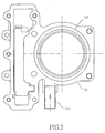
- Fig. 2 is a bird's eye view of a body of the cylinder of the present invention.
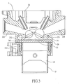
- Fig. 3 is a sectional view showing a local part of an engine of the present invention.
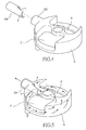
- Fig. 4 is an exploded view of a retainer and the spatial configuration of the cooling water passage in the cylinder head of the present invention.
- Fig. 5 is a schematic view showing an assembly of the retainer and the spatial configuration of the cooling water passage in the cylinder head of the present invention.
- Fig. 6 is an elevation view of the cylinder head of the present invention.
- Fig. 7 is a schematic view showing an assembly of a spacer and the cylinder as taken from Section A-A from Fig. 6.
- The following descriptions are of exemplary embodiments only, and are not intended to limit the scope, applicability or configuration of the invention in any way. Rather, the following description provides a convenient illustration for implementing exemplary embodiments of the invention. Various changes to the described embodiments may be made in the function and arrangement of the elements described without departing from the scope of the invention as set forth in the appended claims.
- Referring to Fig. 2 for an elevation view of a
cylinder 21 of a water-cooling engine of the present invention, acooling water inlet 211 and awaterway 212 for circulation of the cooling water are provided to thecylinder 21. Now referring to Fig. 3 for a sectional view of anengine 2 of the present invention, theengine 2 includes thecylinder 21, and acylinder head 22 on top of thecylinder 21. Thecylinder head 22 contains anair inlet passage 221, anexhaustion passage 222 to discharge the exhaust, acombustion chamber 23 where the air-fuel mixture is combusted, apiston 24 to engage in reciprocal motion inside thecylinder 21, and avalve mechanism seat 25 to accommodate multiple valves. Aspacer 26 is provided between thecylinder 21 and the cylinder head of theengine 2, wherein a cooling-water outlet 223 (as illustrated in Fig. 7) to discharge the cooling water is provided to the cylinder head. Thevalve mechanism seat 25 is comprised of an airinlet valve seat 251 and anexhaustion valve seat 252. Aport 261 connecting through the cooling water is provided to thespacer 26 on the side of theexhaustion passage 222. - Fig. 5 is a schematic view showing the spatial configuration of a cooling water passage B in the
cylinder head 22 of the present invention. Aretainer 224 related to a hollow pipe is provided to thewater outlet 223 of the cooling water in relation to the cooling outwater 223 and has one end provided with a gap a, and a limitation piece b in relation to the gap a. - As illustrated in Figs. 2 and 3, the cooling water flows from the water-
cooling inlet 211 in thecylinder 21 into the waterway of thecylinder 21 when theengine 2 runs. The cooling water flowing into thewaterway 212 flows upward to arrive at thespacer 26 where the cooling water will flow into thecylinder head 22 through the coolingwater connection port 261 provided on the side of theexhaustion passage 222 due to the packing status created between thecylinder 21 and thecylinder head 22 by thespacer 26. As illustrated in Fig. 5, whereas theretainer 224 is inserted to thecooling water outlet 223 of thecylinder head 22, the cooling water is frustrated by the limitation piece b extending from theretainer 224 when the cooling water flows from the coolingwater connection port 261 into thecylinder head 22. Accordingly, the cooling water is forced to first pass through an exhaust passage side C at higher temperature before flowing through an air inlet passage side D to finally exit from thecooling water outlet 223. - As illustrated in Figs. 5, 6, and 7, the cooling water as separated by the
retainer 224 upon flowing into thecylinder head 22 through the coolingwater connection port 261 of thespacer 26 passes by theexhaustion valve seat 252 on the exhaustion passage side C at higher temperature before passing by theair inlet valve 251 on the air inlet passage side D at lower temperature before exiting from thepipe retainer 224 inserted to thecooling water outlet 223 to complete the cooling cycle. The cooling water by cooling first the exhaustion passage side C at higher temperature before cooling the air inlet passage side D at lower temperature consistently absorbs the heat at high temperature produced on thecylinder head 22 while theengine 2 is running to achieve the results of reducing the temperature of thecylinder head 22, thus theengine 2. - Furthermore, the
retainer 224 may be forthwith cast to thecylinder head 22 during the casting process of thecylinder head 22 as illustrated in Fig. 7; or alternatively, theretainer 224 is fixed in thecooling water outlet 223 upon the completion of the casting process of thecylinder head 22. - The construction of a cooling water passage for the cylinder head of engine disclosed in the present invention corrects the flaw of failing to provide consistent temperature reduction of the prior art by providing the
retainer 224 at thecooling water outlet 223 of thecylinder head 22, extending the flow route for the cooling water and for the cooling water to cool first the exhaustion passage side C at a higher temperature before cooling the air inlet passage side D at a lower temperature to consistently absorb the heat at high temperature produced to the cylinder head while the engine is running, thus upgrading heat dissipation results for the cylinder head as a whole and avoiding deformation to mechanical parts due to inconsistent heat absorption. - It will be understood that each of the elements described above, or two or more together may also find a useful application in other types of methods differing from the type described above.
- While certain novel features of this invention have been shown and described and are pointed out in the annexed claim, it is not intended to be limited to the details above, since it will be understood that various omissions, modifications, substitutions and changes in the forms and details of the device illustrated and in its operation can be made by those skilled in the art without departing in any way from the spirit of the present invention.
Claims (5)
- A cooling water passage in engine cylinder head comprised of an engine including a cylinder, a cylinder head on top of the cylinder, a spacer disposed between the cylinder and the cylinder head; the cylinder head including an air inlet passage, an exhaustion passage, a combustion chamber characterized in that the cooling water passage is provided with a port to connect cooling water on the side of the exhaustion passage side, cooling water flowing into through the cooling water connection port being limited by a retainer and force to flow first to pass by the side of the exhaustion passage before passing through the air inlet passage side, and finally exiting from the cooling water of the cylinder.
- The cooling water passage in engine cylinder head of Claim 1, wherein, the retainer relates to a hollow pipe with one end formed with a gap and a limitation piece in relation to the gap.
- The cooling water passage in engine cylinder head of Claim 1, wherein, the retainer is directly cast in the cylinder head.
- The cooling water passage in engine cylinder head of Claim 1, wherein, the retainer is fixed in the cooling water outlet upon the cylinder head is cast.
- The cooling water passage in engine cylinder head of Claim 1, wherein, the cooling water first passes by an exhaustion valve seat located on the side of the exhaustion passage before flowing to an air inlet valve seat located on the side of the air inlet passage.
Priority Applications (4)
| Application Number | Priority Date | Filing Date | Title |
|---|---|---|---|
| ES04021096T ES2358326T3 (en) | 2004-09-04 | 2004-09-04 | REFRIGERATION WATER CONDUCT OF A MOTOR HEAD. |
| DE602004031421T DE602004031421D1 (en) | 2004-09-04 | 2004-09-04 | Cooling water channel in a cylinder head |
| AT04021096T ATE498763T1 (en) | 2004-09-04 | 2004-09-04 | COOLING WATER CHANNEL IN A CYLINDER HEAD |
| EP04021096A EP1632653B1 (en) | 2004-09-04 | 2004-09-04 | Cooling water passage in engine cylinder head |
Applications Claiming Priority (1)
| Application Number | Priority Date | Filing Date | Title |
|---|---|---|---|
| EP04021096A EP1632653B1 (en) | 2004-09-04 | 2004-09-04 | Cooling water passage in engine cylinder head |
Publications (2)
| Publication Number | Publication Date |
|---|---|
| EP1632653A1 true EP1632653A1 (en) | 2006-03-08 |
| EP1632653B1 EP1632653B1 (en) | 2011-02-16 |
Family
ID=34926430
Family Applications (1)
| Application Number | Title | Priority Date | Filing Date |
|---|---|---|---|
| EP04021096A Expired - Lifetime EP1632653B1 (en) | 2004-09-04 | 2004-09-04 | Cooling water passage in engine cylinder head |
Country Status (4)
| Country | Link |
|---|---|
| EP (1) | EP1632653B1 (en) |
| AT (1) | ATE498763T1 (en) |
| DE (1) | DE602004031421D1 (en) |
| ES (1) | ES2358326T3 (en) |
Cited By (4)
| Publication number | Priority date | Publication date | Assignee | Title |
|---|---|---|---|---|
| US20130233258A1 (en) * | 2009-11-18 | 2013-09-12 | Harley-Davidson Motor Company Group, LLC | Cylinder head cooling system |
| US20140238319A1 (en) * | 2013-02-26 | 2014-08-28 | Mclaren Automotive Limited | Engine cooling |
| CN113236434A (en) * | 2021-04-27 | 2021-08-10 | 重庆隆鑫机车有限公司 | Cooling water jacket and engine |
| CN119288692A (en) * | 2024-11-07 | 2025-01-10 | 浙江绿色智行科创有限公司 | Engine water jacket structure |
Citations (6)
| Publication number | Priority date | Publication date | Assignee | Title |
|---|---|---|---|---|
| US2077224A (en) * | 1931-06-26 | 1937-04-13 | Gen Electric | Combustion engine |
| US3115125A (en) | 1961-09-25 | 1963-12-24 | Charles O Spencer | Internal combustion engine cooling system |
| US3155084A (en) * | 1962-03-28 | 1964-11-03 | Caterpillar Tractor Co | Cooling means for internal combustion engines |
| JPH04255554A (en) * | 1991-02-06 | 1992-09-10 | Suzuki Motor Corp | Cylinder head cooling device for four-cycle engine |
| JPH11229955A (en) * | 1998-02-13 | 1999-08-24 | Daihatsu Motor Co Ltd | Structure of cylinder head in internal combustion engine |
| DE20216452U1 (en) * | 2002-10-25 | 2002-12-19 | FEV Motorentechnik GmbH, 52078 Aachen | Cylinder head for a water-cooled piston internal combustion engine with internal reinforcement |
-
2004
- 2004-09-04 AT AT04021096T patent/ATE498763T1/en not_active IP Right Cessation
- 2004-09-04 EP EP04021096A patent/EP1632653B1/en not_active Expired - Lifetime
- 2004-09-04 ES ES04021096T patent/ES2358326T3/en not_active Expired - Lifetime
- 2004-09-04 DE DE602004031421T patent/DE602004031421D1/en not_active Expired - Lifetime
Patent Citations (6)
| Publication number | Priority date | Publication date | Assignee | Title |
|---|---|---|---|---|
| US2077224A (en) * | 1931-06-26 | 1937-04-13 | Gen Electric | Combustion engine |
| US3115125A (en) | 1961-09-25 | 1963-12-24 | Charles O Spencer | Internal combustion engine cooling system |
| US3155084A (en) * | 1962-03-28 | 1964-11-03 | Caterpillar Tractor Co | Cooling means for internal combustion engines |
| JPH04255554A (en) * | 1991-02-06 | 1992-09-10 | Suzuki Motor Corp | Cylinder head cooling device for four-cycle engine |
| JPH11229955A (en) * | 1998-02-13 | 1999-08-24 | Daihatsu Motor Co Ltd | Structure of cylinder head in internal combustion engine |
| DE20216452U1 (en) * | 2002-10-25 | 2002-12-19 | FEV Motorentechnik GmbH, 52078 Aachen | Cylinder head for a water-cooled piston internal combustion engine with internal reinforcement |
Non-Patent Citations (2)
| Title |
|---|
| PATENT ABSTRACTS OF JAPAN vol. 017, no. 034 (M - 1357) 22 January 1993 (1993-01-22) * |
| PATENT ABSTRACTS OF JAPAN vol. 1999, no. 13 30 November 1999 (1999-11-30) * |
Cited By (7)
| Publication number | Priority date | Publication date | Assignee | Title |
|---|---|---|---|---|
| US20130233258A1 (en) * | 2009-11-18 | 2013-09-12 | Harley-Davidson Motor Company Group, LLC | Cylinder head cooling system |
| US8939115B2 (en) * | 2009-11-18 | 2015-01-27 | Harley-Davidson Motor Company Group, LLC | Cylinder head cooling system |
| US20140238319A1 (en) * | 2013-02-26 | 2014-08-28 | Mclaren Automotive Limited | Engine cooling |
| US9447748B2 (en) * | 2013-02-26 | 2016-09-20 | Mclaren Automotive Limited | Cylinder head with cooling channel |
| GB2511136B (en) * | 2013-02-26 | 2019-12-04 | Mclaren Automotive Ltd | Engine cooling |
| CN113236434A (en) * | 2021-04-27 | 2021-08-10 | 重庆隆鑫机车有限公司 | Cooling water jacket and engine |
| CN119288692A (en) * | 2024-11-07 | 2025-01-10 | 浙江绿色智行科创有限公司 | Engine water jacket structure |
Also Published As
| Publication number | Publication date |
|---|---|
| DE602004031421D1 (en) | 2011-03-31 |
| ATE498763T1 (en) | 2011-03-15 |
| EP1632653B1 (en) | 2011-02-16 |
| ES2358326T3 (en) | 2011-05-09 |
Similar Documents
| Publication | Publication Date | Title |
|---|---|---|
| CN205089463U (en) | Explosive motor , engine and cylinder head packing ring | |
| CN203009061U (en) | An engine cooling system | |
| CN101225776B (en) | Monolithic cylinder-crankcase | |
| US8051810B2 (en) | Coolant passage within a cylinder head of an internal combustion engine | |
| KR20090132804A (en) | EBR valve integrated cooling system | |
| CN101111669B (en) | internal combustion engine | |
| EP1632653B1 (en) | Cooling water passage in engine cylinder head | |
| EP2402573B1 (en) | Coolant water duct device for internal combustion engine | |
| JP2009264255A (en) | Cooling device of fuel injection valve | |
| EP2620612B1 (en) | Internal combustion engine and straddle-type vehicle including the same | |
| CN109026322B (en) | Cooling oil passage structure of engine | |
| JP4486477B2 (en) | Cooling water passage structure of engine cylinder head | |
| EP2481908A1 (en) | Exhaust gas recirculation system | |
| US11549460B2 (en) | Water cooled engine | |
| CN115523047A (en) | Engine assembly | |
| CN115539236A (en) | Engine assembly and warm-up system | |
| CN102678372A (en) | Cylinder head heat dissipation structure of air-cooled engine | |
| KR100828832B1 (en) | EZR device of engine | |
| CN109026321B (en) | Cooling oil passage structure of engine | |
| KR100409569B1 (en) | Cooling water nozzle of cylinder head | |
| CN107250518B (en) | Cylinder head and engine | |
| KR101004255B1 (en) | Automotive EJR and Swirl System Integrated Intake Manifold | |
| JP7834876B2 (en) | Automobiles, especially internal combustion engines of powered vehicles | |
| JP2004332656A (en) | Secondary combustion chamber diesel engine | |
| CN101235762A (en) | Engine heat dissipation structure |
Legal Events
| Date | Code | Title | Description |
|---|---|---|---|
| PUAI | Public reference made under article 153(3) epc to a published international application that has entered the european phase |
Free format text: ORIGINAL CODE: 0009012 |
|
| AK | Designated contracting states |
Kind code of ref document: A1 Designated state(s): AT BE BG CH CY CZ DE DK EE ES FI FR GB GR HU IE IT LI LU MC NL PL PT RO SE SI SK TR |
|
| AX | Request for extension of the european patent |
Extension state: AL HR LT LV MK |
|
| 17P | Request for examination filed |
Effective date: 20060904 |
|
| AKX | Designation fees paid |
Designated state(s): AT BE BG CH CY CZ DE DK EE ES FI FR GB GR HU IE IT LI LU MC NL PL PT RO SE SI SK TR |
|
| 17Q | First examination report despatched |
Effective date: 20081106 |
|
| GRAP | Despatch of communication of intention to grant a patent |
Free format text: ORIGINAL CODE: EPIDOSNIGR1 |
|
| GRAS | Grant fee paid |
Free format text: ORIGINAL CODE: EPIDOSNIGR3 |
|
| GRAA | (expected) grant |
Free format text: ORIGINAL CODE: 0009210 |
|
| AK | Designated contracting states |
Kind code of ref document: B1 Designated state(s): AT BE BG CH CY CZ DE DK EE ES FI FR GB GR HU IE IT LI LU MC NL PL PT RO SE SI SK TR |
|
| REG | Reference to a national code |
Ref country code: GB Ref legal event code: FG4D |
|
| REG | Reference to a national code |
Ref country code: CH Ref legal event code: EP |
|
| REG | Reference to a national code |
Ref country code: IE Ref legal event code: FG4D |
|
| REF | Corresponds to: |
Ref document number: 602004031421 Country of ref document: DE Date of ref document: 20110331 Kind code of ref document: P |
|
| REG | Reference to a national code |
Ref country code: DE Ref legal event code: R096 Ref document number: 602004031421 Country of ref document: DE Effective date: 20110331 |
|
| REG | Reference to a national code |
Ref country code: ES Ref legal event code: FG2A Ref document number: 2358326 Country of ref document: ES Kind code of ref document: T3 Effective date: 20110426 |
|
| REG | Reference to a national code |
Ref country code: NL Ref legal event code: VDEP Effective date: 20110216 |
|
| PG25 | Lapsed in a contracting state [announced via postgrant information from national office to epo] |
Ref country code: SE Free format text: LAPSE BECAUSE OF FAILURE TO SUBMIT A TRANSLATION OF THE DESCRIPTION OR TO PAY THE FEE WITHIN THE PRESCRIBED TIME-LIMIT Effective date: 20110216 Ref country code: PT Free format text: LAPSE BECAUSE OF FAILURE TO SUBMIT A TRANSLATION OF THE DESCRIPTION OR TO PAY THE FEE WITHIN THE PRESCRIBED TIME-LIMIT Effective date: 20110616 Ref country code: GR Free format text: LAPSE BECAUSE OF FAILURE TO SUBMIT A TRANSLATION OF THE DESCRIPTION OR TO PAY THE FEE WITHIN THE PRESCRIBED TIME-LIMIT Effective date: 20110517 |
|
| PG25 | Lapsed in a contracting state [announced via postgrant information from national office to epo] |
Ref country code: BE Free format text: LAPSE BECAUSE OF FAILURE TO SUBMIT A TRANSLATION OF THE DESCRIPTION OR TO PAY THE FEE WITHIN THE PRESCRIBED TIME-LIMIT Effective date: 20110216 Ref country code: CY Free format text: LAPSE BECAUSE OF FAILURE TO SUBMIT A TRANSLATION OF THE DESCRIPTION OR TO PAY THE FEE WITHIN THE PRESCRIBED TIME-LIMIT Effective date: 20110216 Ref country code: AT Free format text: LAPSE BECAUSE OF FAILURE TO SUBMIT A TRANSLATION OF THE DESCRIPTION OR TO PAY THE FEE WITHIN THE PRESCRIBED TIME-LIMIT Effective date: 20110216 Ref country code: NL Free format text: LAPSE BECAUSE OF FAILURE TO SUBMIT A TRANSLATION OF THE DESCRIPTION OR TO PAY THE FEE WITHIN THE PRESCRIBED TIME-LIMIT Effective date: 20110216 Ref country code: PL Free format text: LAPSE BECAUSE OF FAILURE TO SUBMIT A TRANSLATION OF THE DESCRIPTION OR TO PAY THE FEE WITHIN THE PRESCRIBED TIME-LIMIT Effective date: 20110216 Ref country code: SI Free format text: LAPSE BECAUSE OF FAILURE TO SUBMIT A TRANSLATION OF THE DESCRIPTION OR TO PAY THE FEE WITHIN THE PRESCRIBED TIME-LIMIT Effective date: 20110216 Ref country code: FI Free format text: LAPSE BECAUSE OF FAILURE TO SUBMIT A TRANSLATION OF THE DESCRIPTION OR TO PAY THE FEE WITHIN THE PRESCRIBED TIME-LIMIT Effective date: 20110216 Ref country code: BG Free format text: LAPSE BECAUSE OF FAILURE TO SUBMIT A TRANSLATION OF THE DESCRIPTION OR TO PAY THE FEE WITHIN THE PRESCRIBED TIME-LIMIT Effective date: 20110516 |
|
| PG25 | Lapsed in a contracting state [announced via postgrant information from national office to epo] |
Ref country code: DK Free format text: LAPSE BECAUSE OF FAILURE TO SUBMIT A TRANSLATION OF THE DESCRIPTION OR TO PAY THE FEE WITHIN THE PRESCRIBED TIME-LIMIT Effective date: 20110216 Ref country code: EE Free format text: LAPSE BECAUSE OF FAILURE TO SUBMIT A TRANSLATION OF THE DESCRIPTION OR TO PAY THE FEE WITHIN THE PRESCRIBED TIME-LIMIT Effective date: 20110216 |
|
| PG25 | Lapsed in a contracting state [announced via postgrant information from national office to epo] |
Ref country code: RO Free format text: LAPSE BECAUSE OF FAILURE TO SUBMIT A TRANSLATION OF THE DESCRIPTION OR TO PAY THE FEE WITHIN THE PRESCRIBED TIME-LIMIT Effective date: 20110216 Ref country code: SK Free format text: LAPSE BECAUSE OF FAILURE TO SUBMIT A TRANSLATION OF THE DESCRIPTION OR TO PAY THE FEE WITHIN THE PRESCRIBED TIME-LIMIT Effective date: 20110216 Ref country code: CZ Free format text: LAPSE BECAUSE OF FAILURE TO SUBMIT A TRANSLATION OF THE DESCRIPTION OR TO PAY THE FEE WITHIN THE PRESCRIBED TIME-LIMIT Effective date: 20110216 |
|
| PLBE | No opposition filed within time limit |
Free format text: ORIGINAL CODE: 0009261 |
|
| STAA | Information on the status of an ep patent application or granted ep patent |
Free format text: STATUS: NO OPPOSITION FILED WITHIN TIME LIMIT |
|
| 26N | No opposition filed |
Effective date: 20111117 |
|
| REG | Reference to a national code |
Ref country code: DE Ref legal event code: R097 Ref document number: 602004031421 Country of ref document: DE Effective date: 20111117 |
|
| PG25 | Lapsed in a contracting state [announced via postgrant information from national office to epo] |
Ref country code: MC Free format text: LAPSE BECAUSE OF NON-PAYMENT OF DUE FEES Effective date: 20110930 |
|
| REG | Reference to a national code |
Ref country code: CH Ref legal event code: PL |
|
| GBPC | Gb: european patent ceased through non-payment of renewal fee |
Effective date: 20110904 |
|
| REG | Reference to a national code |
Ref country code: IE Ref legal event code: MM4A |
|
| PG25 | Lapsed in a contracting state [announced via postgrant information from national office to epo] |
Ref country code: IE Free format text: LAPSE BECAUSE OF NON-PAYMENT OF DUE FEES Effective date: 20110904 Ref country code: LI Free format text: LAPSE BECAUSE OF NON-PAYMENT OF DUE FEES Effective date: 20110930 Ref country code: CH Free format text: LAPSE BECAUSE OF NON-PAYMENT OF DUE FEES Effective date: 20110930 |
|
| PG25 | Lapsed in a contracting state [announced via postgrant information from national office to epo] |
Ref country code: GB Free format text: LAPSE BECAUSE OF NON-PAYMENT OF DUE FEES Effective date: 20110904 |
|
| PG25 | Lapsed in a contracting state [announced via postgrant information from national office to epo] |
Ref country code: LU Free format text: LAPSE BECAUSE OF NON-PAYMENT OF DUE FEES Effective date: 20110904 |
|
| PG25 | Lapsed in a contracting state [announced via postgrant information from national office to epo] |
Ref country code: TR Free format text: LAPSE BECAUSE OF FAILURE TO SUBMIT A TRANSLATION OF THE DESCRIPTION OR TO PAY THE FEE WITHIN THE PRESCRIBED TIME-LIMIT Effective date: 20110216 |
|
| PG25 | Lapsed in a contracting state [announced via postgrant information from national office to epo] |
Ref country code: HU Free format text: LAPSE BECAUSE OF FAILURE TO SUBMIT A TRANSLATION OF THE DESCRIPTION OR TO PAY THE FEE WITHIN THE PRESCRIBED TIME-LIMIT Effective date: 20110216 |
|
| REG | Reference to a national code |
Ref country code: FR Ref legal event code: PLFP Year of fee payment: 13 |
|
| REG | Reference to a national code |
Ref country code: FR Ref legal event code: PLFP Year of fee payment: 14 |
|
| REG | Reference to a national code |
Ref country code: FR Ref legal event code: PLFP Year of fee payment: 15 |
|
| PGFP | Annual fee paid to national office [announced via postgrant information from national office to epo] |
Ref country code: IT Payment date: 20180925 Year of fee payment: 15 Ref country code: FR Payment date: 20180924 Year of fee payment: 15 Ref country code: DE Payment date: 20180828 Year of fee payment: 15 |
|
| PGFP | Annual fee paid to national office [announced via postgrant information from national office to epo] |
Ref country code: ES Payment date: 20181022 Year of fee payment: 15 |
|
| REG | Reference to a national code |
Ref country code: DE Ref legal event code: R119 Ref document number: 602004031421 Country of ref document: DE |
|
| PG25 | Lapsed in a contracting state [announced via postgrant information from national office to epo] |
Ref country code: DE Free format text: LAPSE BECAUSE OF NON-PAYMENT OF DUE FEES Effective date: 20200401 |
|
| PG25 | Lapsed in a contracting state [announced via postgrant information from national office to epo] |
Ref country code: IT Free format text: LAPSE BECAUSE OF NON-PAYMENT OF DUE FEES Effective date: 20190904 |
|
| PG25 | Lapsed in a contracting state [announced via postgrant information from national office to epo] |
Ref country code: FR Free format text: LAPSE BECAUSE OF NON-PAYMENT OF DUE FEES Effective date: 20190930 |
|
| REG | Reference to a national code |
Ref country code: ES Ref legal event code: FD2A Effective date: 20210127 |
|
| PG25 | Lapsed in a contracting state [announced via postgrant information from national office to epo] |
Ref country code: ES Free format text: LAPSE BECAUSE OF NON-PAYMENT OF DUE FEES Effective date: 20190905 |