EP1630932A1 - Spacers for axial spacing enclosure rings and shields for rotor of an electrical machine - Google Patents
Spacers for axial spacing enclosure rings and shields for rotor of an electrical machine Download PDFInfo
- Publication number
- EP1630932A1 EP1630932A1 EP05255231A EP05255231A EP1630932A1 EP 1630932 A1 EP1630932 A1 EP 1630932A1 EP 05255231 A EP05255231 A EP 05255231A EP 05255231 A EP05255231 A EP 05255231A EP 1630932 A1 EP1630932 A1 EP 1630932A1
- Authority
- EP
- European Patent Office
- Prior art keywords
- ring
- rotor
- rings
- spacers
- spacer
- Prior art date
- Legal status (The legal status is an assumption and is not a legal conclusion. Google has not performed a legal analysis and makes no representation as to the accuracy of the status listed.)
- Granted
Links
- 125000006850 spacer group Chemical group 0.000 title claims abstract description 50
- 230000005405 multipole Effects 0.000 claims abstract description 7
- 230000037431 insertion Effects 0.000 claims abstract 2
- 238000003780 insertion Methods 0.000 claims abstract 2
- 238000004804 winding Methods 0.000 claims description 24
- 239000004020 conductor Substances 0.000 claims description 2
- 238000009423 ventilation Methods 0.000 abstract description 3
- 230000000712 assembly Effects 0.000 description 3
- 238000000429 assembly Methods 0.000 description 3
- 239000002826 coolant Substances 0.000 description 3
- 238000001816 cooling Methods 0.000 description 2
- 238000010276 construction Methods 0.000 description 1
- 238000005242 forging Methods 0.000 description 1
- 238000009434 installation Methods 0.000 description 1
- 230000014759 maintenance of location Effects 0.000 description 1
- 239000000463 material Substances 0.000 description 1
- 230000000717 retained effect Effects 0.000 description 1
Images



Classifications
-
- H—ELECTRICITY
- H02—GENERATION; CONVERSION OR DISTRIBUTION OF ELECTRIC POWER
- H02K—DYNAMO-ELECTRIC MACHINES
- H02K3/00—Details of windings
- H02K3/46—Fastening of windings on the stator or rotor structure
- H02K3/52—Fastening salient pole windings or connections thereto
- H02K3/527—Fastening salient pole windings or connections thereto applicable to rotors only
-
- H—ELECTRICITY
- H02—GENERATION; CONVERSION OR DISTRIBUTION OF ELECTRIC POWER
- H02K—DYNAMO-ELECTRIC MACHINES
- H02K1/00—Details of the magnetic circuit
- H02K1/06—Details of the magnetic circuit characterised by the shape, form or construction
- H02K1/22—Rotating parts of the magnetic circuit
- H02K1/32—Rotating parts of the magnetic circuit with channels or ducts for flow of cooling medium
Definitions
- the present invention relates to a rotor configuration for an electrical machine and particularly to spacers for axially spacing enclosure rings and annular shields about the pole faces and field winding modules of an electrical machine.
- a rotor configuration in a particular electrical machine, includes a multi-pole rotor core for rotation about an axis.
- a plurality of field winding modules are respectively disposed about each pole of the multi-pole rotor core and an enclosure is disposed over the field winding modules to contain the latter about the rotor core.
- a magnetic shield is disposed about and between the field winding modules and the enclosure.
- the enclosure forms part of a containment system for the windings.
- the windings in the rotor require cooling and typically a cooling medium flows through defined passages in the rotor and exits into the air gap between the rotor and the stator.
- Part of the enclosure includes rings. Accordingly, there is a need to maintain the enclosure rings about the field winding modules axially positioned relative to one another and along the rotor shaft to provide well-defined locations for radial discharge of the cooling medium, as well as to enable electrical connection of the amortisseur shield segments, while simultaneously affording assembly aids to render the rotor architecture easier to assemble.
- a spacer is provided in the groove and extends outwardly between the pair of rings to maintain a predetermined axial spacing between the rings.
- the spacer may comprise a rectilinear base with a radial outward projection for engaging between the rings or a generally dovetail-shaped base for reception and retention in a complementary-shaped groove in the rotor core.
- the rotor shaft includes a multi-pole rotor core having field winding modules disposed about the rotor core, axially spaced enclosure rings disposed over the field winding modules, a groove extending along each pole of the rotor core, and shield segments between the enclosure rings and the rotor core.
- Spacers are provided in the groove of the rotor core with projections extending between the axially adjacent shield segments and enclosure rings.
- the spacers are formed of electrically conductive material whereby a continuous electrical current path is provided between axially adjacent shield segments. The gap between the shield segments, as well as the axially adjacent enclosure rings, may be controlled to throttle the cooling flow.
- the end edges of the shield segments spaced from one another may have recesses for engaging about the radial projections of the spacers with the recesses being variously sized to control the spacing between opposed end edges of the shield segments.
- the end edges of the axially adjacent rings may butt the radial projections and thus be set back from the end edges of the shield segments.
- a rotor for an electric machine comprising a rotor shaft including a multi-pole rotor core having pole faces, field winding modules respectively disposed on the rotor core, first and second axially spaced enclosure rings disposed over the field winding modules, the rotor core having a groove extending along each pole face of the rotor core and a first spacer disposed in each groove and between the first and second rings to maintain the pair of enclosure rings in a predetermined axial spacing relative to one another.
- an electric machine comprising a rotor having an axis, field windings disposed about the rotor, first and second axially spaced enclosure rings disposed over the field windings, the rotor having a pair of grooves extending along outer arcuate faces at circumferential locations about the rotor of the rotor and a first spacer disposed in each groove and between the first and second rings to maintain the pair of enclosure rings in a predetermined axial spacing relative to one another.
- a generator rotor 30 includes a rotor shaft 31, a multi-pole magnetic core 32 (a two-pole core being shown) and a plurality of field winding assemblies 34, one for each pole, and corresponding pole faces 36.
- the construction and materials of the magnetic core 32 and winding assemblies 34 are known.
- the prefabricated winding assemblies are disposed over the parallel side forging forming the rotor body and are curved in an arc generally concentric with the rotor body.
- the rotor is disposed within a stator and an air gap exists between an enclosure about the rotor and the inner surface of the stator.
- a quadrature axis Q extending normal to both the axis of rotation of the rotor and the flat side surfaces.
- the direct axis D extends normal to the Q axis and the axis of rotation.
- Each rotor body pole face 36 includes, as illustrated in Figure 3, an arcuate surface 38 having an axially extending groove 40 opening through an end face 41 of each pole. While the groove may take many different forms, i.e., a rectilinear or keyhole shape, a dovetail-shaped groove 40 having a laterally enlarged base 47 ( Figure 4) is preferred. It will be appreciated that enclosure rings 42 are disposed about the rotor body, essentially encapsulating the rotor body and the field windings. Also, amortisseur shield rings or segments 44 ( Figures 7-9) are disposed about the rotor body and field windings at axially spaced positions therealong underlying the enclosure rings 42.
- axially spacing the rings from one another provides vent passages for the field windings to dissipate heat from the rotor body into the gap between the rotor body and the stator.
- the rotor body and field windings do not heat uniformly and therefore a variable spacing between the enclosure and shield rings is desirable.
- the various rings are axially spaced one from the other by spacers 46, as illustrated in Figures 4 and 4a.
- the spacers 46 include a base 48 and a projection 50 extending outwardly from base 48.
- the spacer 46 is generally rectilinear, with the base 48 configured for sliding engagement along the slot 40 with the projection 50 extending above the surface of the pole face 36 sufficiently to be engaged by the shield and enclosure rings. Spacers 46 therefore may be inserted or placed within the groove 40 in sequence as the rings are placed about the rotor body.
- the rings i.e., one shield ring and one enclosure ring
- the rings may be placed on the rotor body alternating with spacers 46 located in the grooves 40 in each of the pole faces 36 whereby the sets of rings, i.e., shield and enclosure rings, may be axially spaced one from the other by the projections 50.
- the spacers need not be retained within the groove 40 since the legs 52 of the spacers 46 extend longitudinally beyond the projections 50 to underlie the rings 44 and 42.
- the rings maintain the spacers on the rotor body 32. It will be appreciated that the spacers restrain the enclosure and shield rings against axial movement and provide predictable ring spacing for discharge of field winding ventilation. Variable axial spacing can be achieved depending upon the rotor ventilation needs by enlarging or reducing the axial extent of the projection 50 of the predetermined spacers 46.
- the spacer is made of a different configuration than the spacer illustrated in Figure 4a.
- the spacer 60 includes a dovetail-shaped base 62 having an upstanding, generally cylindrical projection 64 for extending out of the groove 40. Consequently, the spacer 60 requires axial installation into the groove 40, alternating with the axial disposition of the shield and enclosure rings.
- the rings may be variably axially spaced from one another along the rotor body by changing the thickness, i.e., diameter, of the projection 64. It will be appreciated that the spacers need not be fixed in the grooves 40 but are restrained in the grooves 40 by the overlying rings which are, after assembly, bonded to the rotor body. The capture of the spacers within the grooves thus does not complicate the assembly of the rings about the rotor.
- the spacer 70 may have a rectilinear base 72 or a dovetail-shaped base as in the preceding embodiment, with a radial outward cylindrical projection 74 having undercuts 76 opening axially along opposite sides.
- the base 72 of the spacer 70 may be provided along the groove 40 with the shield rings engaging in the undercuts 76 along the projections 74.
- the shield rings are axially spaced one from the other to a predetermined spacing, depending upon the thickness of the undercuts 76 of the cylindrical projections 74.
- the enclosure rings 42 are spaced one from the other by the cylindrical projections 74.
- the shield rings are more closely axially spaced to one another than the enclosure rings 42 are axially spaced from one another. Consequently, the shields throttle the flow between the axially spaced enclosure rings 42.
- the shield rings 44 may have arcuate cutouts 80 ( Figure 9) overlying the groove 40 for engaging about the cylindrical projections 74.
- the spacer in this form may have a circular undercut radially outwardly of the base of the spacer with a rectilinear head on the projection.
- the arcuate slots 80 along the shield segments engage about the circular portion of the spacer, while the enclosure rings engage along the linear sides of the square projection on the head. It will be appreciated by placing a notch within the shield segments, the shields cannot rotate about the axis of the rotor.
Landscapes
- Engineering & Computer Science (AREA)
- Power Engineering (AREA)
- Iron Core Of Rotating Electric Machines (AREA)
- Windings For Motors And Generators (AREA)
- Insulation, Fastening Of Motor, Generator Windings (AREA)
Abstract

Description
- The present invention relates to a rotor configuration for an electrical machine and particularly to spacers for axially spacing enclosure rings and annular shields about the pole faces and field winding modules of an electrical machine.
- In a particular electrical machine, a rotor configuration includes a multi-pole rotor core for rotation about an axis. A plurality of field winding modules are respectively disposed about each pole of the multi-pole rotor core and an enclosure is disposed over the field winding modules to contain the latter about the rotor core. A magnetic shield is disposed about and between the field winding modules and the enclosure.
- The enclosure, as well as the shield, forms part of a containment system for the windings. It will be appreciated that the windings in the rotor require cooling and typically a cooling medium flows through defined passages in the rotor and exits into the air gap between the rotor and the stator. Part of the enclosure includes rings. Accordingly, there is a need to maintain the enclosure rings about the field winding modules axially positioned relative to one another and along the rotor shaft to provide well-defined locations for radial discharge of the cooling medium, as well as to enable electrical connection of the amortisseur shield segments, while simultaneously affording assembly aids to render the rotor architecture easier to assemble.
- In an exemplary embodiment of the present invention, there is provided at least one groove along each of the pole faces of the rotor core. To maintain a pair of enclosure rings in a predetermined axial position relative to one another along the rotor core, a spacer is provided in the groove and extends outwardly between the pair of rings to maintain a predetermined axial spacing between the rings. The spacer may comprise a rectilinear base with a radial outward projection for engaging between the rings or a generally dovetail-shaped base for reception and retention in a complementary-shaped groove in the rotor core.
- In another aspect of the present invention, the rotor shaft includes a multi-pole rotor core having field winding modules disposed about the rotor core, axially spaced enclosure rings disposed over the field winding modules, a groove extending along each pole of the rotor core, and shield segments between the enclosure rings and the rotor core. Spacers are provided in the groove of the rotor core with projections extending between the axially adjacent shield segments and enclosure rings. The spacers are formed of electrically conductive material whereby a continuous electrical current path is provided between axially adjacent shield segments. The gap between the shield segments, as well as the axially adjacent enclosure rings, may be controlled to throttle the cooling flow. To accomplish this, the end edges of the shield segments spaced from one another may have recesses for engaging about the radial projections of the spacers with the recesses being variously sized to control the spacing between opposed end edges of the shield segments. The end edges of the axially adjacent rings may butt the radial projections and thus be set back from the end edges of the shield segments.
- In a preferred embodiment according to the present invention, there is provided a rotor for an electric machine comprising a rotor shaft including a multi-pole rotor core having pole faces, field winding modules respectively disposed on the rotor core, first and second axially spaced enclosure rings disposed over the field winding modules, the rotor core having a groove extending along each pole face of the rotor core and a first spacer disposed in each groove and between the first and second rings to maintain the pair of enclosure rings in a predetermined axial spacing relative to one another.
- In a further preferred embodiment according to the present invention, there is provided an electric machine comprising a rotor having an axis, field windings disposed about the rotor, first and second axially spaced enclosure rings disposed over the field windings, the rotor having a pair of grooves extending along outer arcuate faces at circumferential locations about the rotor of the rotor and a first spacer disposed in each groove and between the first and second rings to maintain the pair of enclosure rings in a predetermined axial spacing relative to one another.
- Embodiments of the invention will now be described, by way of example, with reference to the accompanying drawings, in which:
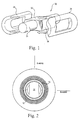
- FIGURE 1 is a perspective view of a preferred rotor in an electrical machine according to the present invention;
- FIGURE 2 is a schematic illustration of the rotor of Figure 1 and a stator as viewed from an end of the electrical machine;
- FIGURE 3 is a fragmentary perspective view with parts removed illustrating the rotor body with axially spaced enclosure rings about the body;
- FIGURE 4 is an enlarged fragmentary perspective view thereof;
- FIGURE 4a is an enlarged perspective view of a spacer used to axially space the enclosure rings illustrated in Figures 3 and 4;
- FIGURE 5 is a perspective view of a further form of spacer ring;
- FIGURE 6 is a fragmentary cross-sectional view of the rotor body taken generally about line 6-6 in Figure 4;
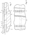
- FIGURE 7 is a view similar to Figure 6, illustrating spacers providing a gap between axially adjacent shields and enclosure rings;
- FIGURE 8 is a plan view thereof; and
- FIGURE 9 is a plan view of the axially spaced shield.
- A
generator rotor 30 includes arotor shaft 31, a multi-pole magnetic core 32 (a two-pole core being shown) and a plurality offield winding assemblies 34, one for each pole, andcorresponding pole faces 36. The construction and materials of themagnetic core 32 andwinding assemblies 34 are known. The prefabricated winding assemblies are disposed over the parallel side forging forming the rotor body and are curved in an arc generally concentric with the rotor body. As illustrated in Figure 2, the rotor is disposed within a stator and an air gap exists between an enclosure about the rotor and the inner surface of the stator. For orientation purposes, there is illustrated in Figure 2 a quadrature axis Q extending normal to both the axis of rotation of the rotor and the flat side surfaces. The direct axis D extends normal to the Q axis and the axis of rotation. - Each rotor
body pole face 36 includes, as illustrated in Figure 3, an arcuate surface 38 having an axially extendinggroove 40 opening through anend face 41 of each pole. While the groove may take many different forms, i.e., a rectilinear or keyhole shape, a dovetail-shaped groove 40 having a laterally enlarged base 47 (Figure 4) is preferred. It will be appreciated thatenclosure rings 42 are disposed about the rotor body, essentially encapsulating the rotor body and the field windings. Also, amortisseur shield rings or segments 44 (Figures 7-9) are disposed about the rotor body and field windings at axially spaced positions therealong underlying theenclosure rings 42. As noted previously, axially spacing the rings from one another provides vent passages for the field windings to dissipate heat from the rotor body into the gap between the rotor body and the stator. Also, it will be appreciated that the rotor body and field windings do not heat uniformly and therefore a variable spacing between the enclosure and shield rings is desirable. At the same time, it is desirable to provide well-defined locations for radial discharge of the cooling medium through the rotor body into the gap, to provide a means of electrically connecting the amortisseur shield segments and to provide an assembly aid to make the rotor architecture easier to assemble. - The various rings are axially spaced one from the other by
spacers 46, as illustrated in Figures 4 and 4a. Thespacers 46 include abase 48 and aprojection 50 extending outwardly frombase 48. In Figure 4a, thespacer 46 is generally rectilinear, with thebase 48 configured for sliding engagement along theslot 40 with theprojection 50 extending above the surface of thepole face 36 sufficiently to be engaged by the shield and enclosure rings.Spacers 46 therefore may be inserted or placed within thegroove 40 in sequence as the rings are placed about the rotor body. That is, the rings, i.e., one shield ring and one enclosure ring, may be placed on the rotor body alternating withspacers 46 located in thegrooves 40 in each of thepole faces 36 whereby the sets of rings, i.e., shield and enclosure rings, may be axially spaced one from the other by theprojections 50. The spacers need not be retained within thegroove 40 since thelegs 52 of thespacers 46 extend longitudinally beyond theprojections 50 to underlie therings rotor body 32. It will be appreciated that the spacers restrain the enclosure and shield rings against axial movement and provide predictable ring spacing for discharge of field winding ventilation. Variable axial spacing can be achieved depending upon the rotor ventilation needs by enlarging or reducing the axial extent of theprojection 50 of thepredetermined spacers 46. - In Figures 5 and 6, the spacer is made of a different configuration than the spacer illustrated in Figure 4a. Particularly, in Figures 5 and 6, the
spacer 60 includes a dovetail-shaped base 62 having an upstanding, generallycylindrical projection 64 for extending out of thegroove 40. Consequently, thespacer 60 requires axial installation into thegroove 40, alternating with the axial disposition of the shield and enclosure rings. As with the prior embodiment, the rings may be variably axially spaced from one another along the rotor body by changing the thickness, i.e., diameter, of theprojection 64. It will be appreciated that the spacers need not be fixed in thegrooves 40 but are restrained in thegrooves 40 by the overlying rings which are, after assembly, bonded to the rotor body. The capture of the spacers within the grooves thus does not complicate the assembly of the rings about the rotor. - A further form of spacer is illustrated, in Figures 7-9. In this form, the
spacer 70 may have arectilinear base 72 or a dovetail-shaped base as in the preceding embodiment, with a radial outwardcylindrical projection 74 having undercuts 76 opening axially along opposite sides. Thus, thebase 72 of thespacer 70 may be provided along thegroove 40 with the shield rings engaging in theundercuts 76 along theprojections 74. In this manner, the shield rings are axially spaced one from the other to a predetermined spacing, depending upon the thickness of theundercuts 76 of thecylindrical projections 74. As in the prior embodiments, the enclosure rings 42 are spaced one from the other by thecylindrical projections 74. As best illustrated in Figures 7 and 8, the shield rings are more closely axially spaced to one another than the enclosure rings 42 are axially spaced from one another. Consequently, the shields throttle the flow between the axially spaced enclosure rings 42. - In a preferred aspect of this embodiment of the invention, the shield rings 44 may have arcuate cutouts 80 (Figure 9) overlying the
groove 40 for engaging about thecylindrical projections 74. The spacer in this form may have a circular undercut radially outwardly of the base of the spacer with a rectilinear head on the projection. As a consequence, thearcuate slots 80 along the shield segments engage about the circular portion of the spacer, while the enclosure rings engage along the linear sides of the square projection on the head. It will be appreciated by placing a notch within the shield segments, the shields cannot rotate about the axis of the rotor.
Claims (10)
- A rotor for an electric machine comprising:a rotor shaft (31) including a multi-pole rotor core (32) having pole faces (36);field winding (34) modules respectively disposed on the rotor core;first and second axially spaced enclosure rings (42) disposed over the field winding modules;said rotor core (32) having a groove (40) extending along each pole face of the rotor core; anda first spacer (46) disposed in each groove and between said first and second rings to maintain said pair of enclosure rings in a predetermined axial spacing relative to one another.
- A rotor according to Claim 1 wherein the rotor shaft (31) is rotatable about an axis and said grooves (40) extend along said pole faces in directions generally parallel to said axis.
- A rotor according to Claim 2 wherein said grooves (40) open through at least one end face (41) of each pole face to enable insertion of the spacers into the grooves.
- A rotor according to Claim 1 wherein each of said grooves has a base (47) within the pole face having a lateral extent in excess of the width of the groove opening through a face of the pole.
- A rotor according to Claim 1 wherein each said groove has a dovetail configuration and each said spacer has a corresponding dovetail configuration for reception within said groove.
- A rotor according to Claim 1 including a third enclosure ring (42), at least a second spacer (46) in each groove spaced from said first spacer, said first ring being disposed axially between said first and second spacers, said second ring being disposed on one side of said first ring with said first spacer between said first ring and said second ring, said third ring being disposed on an opposite side of said first ring with said second spacer between said first ring and said third ring, thereby enabling said first spacer to axially space said first ring and said second ring from one another and said second spacer to axially space said first ring and said third ring from one another.
- A rotor according to Claim 6 wherein the axial spacing between said first and second ring is different than the axial spacing between said first ring and said third ring.
- A rotor according to Claim 1 including axially spaced electrically conductive generally annular shield segments (44) disposed between the enclosure rings (42) and the field winding modules (34) and engaged with and on opposite sides of said spacers, said spacers being formed of electrically conductive material to provide a continuous electrical current path between spaced electrically conductive shield segments.
- A rotor according to Claim 8 wherein said shield segments adjacent said spacers have a closer axial spacing therebetween than the predetermined axial spacing between said first and second enclosure rings.
- A rotor according to Claim 9 wherein each of said spacers includes a generally radially outwardly extending projection (50) engaged by said pair of enclosure rings and an undercut (76), said shield segments having recesses along marginal axially facing edges to at least partially envelop said undercuts.
Applications Claiming Priority (1)
| Application Number | Priority Date | Filing Date | Title |
|---|---|---|---|
| US10/926,067 US6977460B1 (en) | 2004-08-26 | 2004-08-26 | Spacer for axial spacing enclosure rings and shields in an electrical machine |
Publications (2)
| Publication Number | Publication Date |
|---|---|
| EP1630932A1 true EP1630932A1 (en) | 2006-03-01 |
| EP1630932B1 EP1630932B1 (en) | 2008-01-02 |
Family
ID=35457321
Family Applications (1)
| Application Number | Title | Priority Date | Filing Date |
|---|---|---|---|
| EP05255231A Expired - Lifetime EP1630932B1 (en) | 2004-08-26 | 2005-08-25 | Spacers for axial spacing enclosure rings and shields for rotor of an electrical machine |
Country Status (5)
| Country | Link |
|---|---|
| US (1) | US6977460B1 (en) |
| EP (1) | EP1630932B1 (en) |
| JP (1) | JP2006067788A (en) |
| CN (1) | CN100576690C (en) |
| DE (1) | DE602005004087T2 (en) |
Families Citing this family (1)
| Publication number | Priority date | Publication date | Assignee | Title |
|---|---|---|---|---|
| US8258671B2 (en) * | 2009-05-20 | 2012-09-04 | GM Global Technology Operations LLC | Methods and apparatus for a continuous wound laminate rotor flux path |
Citations (3)
| Publication number | Priority date | Publication date | Assignee | Title |
|---|---|---|---|---|
| US2539747A (en) * | 1949-08-29 | 1951-01-30 | Leland Electric Co | High-speed rotor for dynamoelectric machines |
| EP1124304A2 (en) * | 2000-01-26 | 2001-08-16 | General Electric Company | Conductive structural interface for a non-metallic rotor enclosure |
| US6313561B1 (en) * | 2000-01-26 | 2001-11-06 | General Electric Company | Dynamic blocking restraint of a rotor field winding contained by a non-metallic structural rotor enclosure |
Family Cites Families (31)
| Publication number | Priority date | Publication date | Assignee | Title |
|---|---|---|---|---|
| US4363982A (en) | 1981-01-26 | 1982-12-14 | General Electric Company | Dual curved inlet gap pickup wedge |
| US4543503A (en) | 1983-12-20 | 1985-09-24 | General Electric Company | Ventilated end turns for rotor windings of a dynamoelectric machine |
| JPS60152244A (en) * | 1984-01-20 | 1985-08-10 | Hitachi Ltd | Rotor of rotary electric machine |
| US4667125A (en) | 1985-10-25 | 1987-05-19 | General Electric Company | Rotor slot insulation system for electrical machine and article incorporating same |
| US4709177A (en) | 1986-06-30 | 1987-11-24 | General Electric Company | Ventilated end turns for rotor windings of a dynamoelectric machine |
| US4814655A (en) | 1987-12-21 | 1989-03-21 | General Electric Company | Ventilated gusset for single-layer turns in a dynamoelectric machine |
| US5065064A (en) | 1990-05-31 | 1991-11-12 | General Electric Company | Rotor slot insulation in rotors with subslots |
| US5358432A (en) | 1991-04-03 | 1994-10-25 | General Electric Company | Resilient connectors for a generator/motor rotor |
| US5281877A (en) | 1992-11-13 | 1994-01-25 | General Electric Company | Dynamoelectric machine rotor endwindings with corner cooling passages |
| DE19513457A1 (en) * | 1995-04-08 | 1996-10-10 | Abb Management Ag | Rotor of an electrical machine |
| JPH09285099A (en) * | 1996-04-05 | 1997-10-31 | Tamagawa Seiki Co Ltd | Hybrid step motor |
| US5929550A (en) | 1997-03-20 | 1999-07-27 | General Electric Co. | Ventilated creepage blocks |
| US5886434A (en) | 1997-03-20 | 1999-03-23 | General Electric Co. | Generator field turn copper |
| US5986380A (en) | 1998-08-26 | 1999-11-16 | General Electric Co. | Mechanical constraints for tapered end turns of a generator rotor |
| US6181228B1 (en) | 1999-11-09 | 2001-01-30 | General Electric Company | Superconductive magnet including a cryocooler coldhead |
| US6201462B1 (en) | 1999-11-09 | 2001-03-13 | General Electric Company | Open superconductive magnet having a cryocooler coldhead |
| US6198371B1 (en) | 1999-11-09 | 2001-03-06 | General Electric Company | Open magnet with floor mount |
| US6081178A (en) | 1999-11-15 | 2000-06-27 | General Electric Company | Superconductive magnet having a tube suspension assembly |
| US6590311B1 (en) | 1999-12-06 | 2003-07-08 | General Electric Company | Cross-shaped rotor shaft for electrical machine |
| US6437476B1 (en) | 1999-12-06 | 2002-08-20 | General Electric Company | Multi-pole electric machine including flat winding for generator fields |
| US6239527B1 (en) | 2000-01-26 | 2001-05-29 | General Electric Company | Non-circular field winding enclosure |
| US6495942B1 (en) | 2000-01-26 | 2002-12-17 | General Electric Company | Non-metallic structural rotor enclosure |
| US6339268B1 (en) | 2000-02-02 | 2002-01-15 | General Electric Company | Cooling ventilation circuit for rotor end winding and slot end region cooling |
| US6346753B1 (en) | 2000-04-18 | 2002-02-12 | General Electric Company | Fan and rotor dynamic gas sealing system |
| US6369482B1 (en) | 2000-09-27 | 2002-04-09 | General Electric Company | Generator armature bar support system and related method |
| US6448686B1 (en) | 2000-12-08 | 2002-09-10 | General Electric Company | Packaged stator core and method forming the same |
| US6415613B1 (en) | 2001-03-16 | 2002-07-09 | General Electric Company | Cryogenic cooling system with cooldown and normal modes of operation |
| US6438969B1 (en) | 2001-07-12 | 2002-08-27 | General Electric Company | Cryogenic cooling refrigeration system for rotor having a high temperature super-conducting field winding and method |
| US6442949B1 (en) | 2001-07-12 | 2002-09-03 | General Electric Company | Cryongenic cooling refrigeration system and method having open-loop short term cooling for a superconducting machine |
| US6759770B1 (en) * | 2003-04-11 | 2004-07-06 | General Electric Company | Cooling system for modular field windings of a generator |
| US6979928B2 (en) * | 2003-12-02 | 2005-12-27 | General Electric Company | Axial retention feature for restraining composite reinforcing rings |
-
2004
- 2004-08-26 US US10/926,067 patent/US6977460B1/en not_active Expired - Fee Related
-
2005
- 2005-08-24 JP JP2005242224A patent/JP2006067788A/en active Pending
- 2005-08-25 DE DE602005004087T patent/DE602005004087T2/en not_active Expired - Lifetime
- 2005-08-25 EP EP05255231A patent/EP1630932B1/en not_active Expired - Lifetime
- 2005-08-26 CN CN200510091585A patent/CN100576690C/en not_active Expired - Fee Related
Patent Citations (3)
| Publication number | Priority date | Publication date | Assignee | Title |
|---|---|---|---|---|
| US2539747A (en) * | 1949-08-29 | 1951-01-30 | Leland Electric Co | High-speed rotor for dynamoelectric machines |
| EP1124304A2 (en) * | 2000-01-26 | 2001-08-16 | General Electric Company | Conductive structural interface for a non-metallic rotor enclosure |
| US6313561B1 (en) * | 2000-01-26 | 2001-11-06 | General Electric Company | Dynamic blocking restraint of a rotor field winding contained by a non-metallic structural rotor enclosure |
Also Published As
| Publication number | Publication date |
|---|---|
| DE602005004087T2 (en) | 2009-01-02 |
| EP1630932B1 (en) | 2008-01-02 |
| JP2006067788A (en) | 2006-03-09 |
| CN1741348A (en) | 2006-03-01 |
| DE602005004087D1 (en) | 2008-02-14 |
| CN100576690C (en) | 2009-12-30 |
| US6977460B1 (en) | 2005-12-20 |
Similar Documents
| Publication | Publication Date | Title |
|---|---|---|
| US6229238B1 (en) | Transversal flux machine | |
| EP2553792B1 (en) | Rotor of an electric machine with embedded permanent magnets and electric machine | |
| EP1286446B1 (en) | Permanent magnet rotor and permanent magnet machine | |
| US4788465A (en) | Armature for DC motor | |
| US9467014B2 (en) | Rotor for an electrical machine | |
| EP2853017B1 (en) | Stator of a rotating electric machine | |
| KR20040008090A (en) | Induction motor | |
| JP2012120326A (en) | Interior magnet rotor, motor, and method for assembling motor | |
| US20220255386A1 (en) | Coil, stator, and motor | |
| US10158265B2 (en) | Embedded permanent magnet type rotating electric machine | |
| US20140239763A1 (en) | Dual magnetic phase stator laminations for stator permanent magnet electric machines | |
| GB2511421A (en) | Electrical machines | |
| US20170117760A1 (en) | Rotating electrical machine with flux choking features | |
| JP4644875B2 (en) | End plates used for motors and rotors of motors | |
| US20090026869A1 (en) | Transverse flux reluctance machine and method for manufacturing same | |
| EP1630932B1 (en) | Spacers for axial spacing enclosure rings and shields for rotor of an electrical machine | |
| CN115882630A (en) | rotating electrical machine | |
| US20180205275A1 (en) | Surface mount permanent magnet attachment for electric machine | |
| JP2004173366A (en) | Single-phase induction motor | |
| JP2010239680A (en) | Armature for rotating electrical machine and method for manufacturing the same | |
| US20220294283A1 (en) | Coil, stator, motor, and manufacturing method of stator | |
| JPH08256440A (en) | Permanent magnet type synchronous rotating electric machine rotor | |
| JP2005198463A (en) | Rotating electrical machine housing | |
| JP7600065B2 (en) | Rotating Electric Machine | |
| KR102182353B1 (en) | Rotation electrical machine |
Legal Events
| Date | Code | Title | Description |
|---|---|---|---|
| PUAI | Public reference made under article 153(3) epc to a published international application that has entered the european phase |
Free format text: ORIGINAL CODE: 0009012 |
|
| AK | Designated contracting states |
Kind code of ref document: A1 Designated state(s): AT BE BG CH CY CZ DE DK EE ES FI FR GB GR HU IE IS IT LI LT LU LV MC NL PL PT RO SE SI SK TR |
|
| AX | Request for extension of the european patent |
Extension state: AL BA HR MK YU |
|
| RAP1 | Party data changed (applicant data changed or rights of an application transferred) |
Owner name: GENERAL ELECTRIC COMPANY |
|
| 17P | Request for examination filed |
Effective date: 20060901 |
|
| AKX | Designation fees paid |
Designated state(s): CH DE LI |
|
| GRAP | Despatch of communication of intention to grant a patent |
Free format text: ORIGINAL CODE: EPIDOSNIGR1 |
|
| GRAS | Grant fee paid |
Free format text: ORIGINAL CODE: EPIDOSNIGR3 |
|
| GRAA | (expected) grant |
Free format text: ORIGINAL CODE: 0009210 |
|
| AK | Designated contracting states |
Kind code of ref document: B1 Designated state(s): CH DE LI |
|
| REG | Reference to a national code |
Ref country code: CH Ref legal event code: EP |
|
| REF | Corresponds to: |
Ref document number: 602005004087 Country of ref document: DE Date of ref document: 20080214 Kind code of ref document: P |
|
| REG | Reference to a national code |
Ref country code: CH Ref legal event code: NV Representative=s name: SERVOPATENT GMBH |
|
| REG | Reference to a national code |
Ref country code: CH Ref legal event code: NV Representative=s name: SERVOPATENT GMBH |
|
| PLBE | No opposition filed within time limit |
Free format text: ORIGINAL CODE: 0009261 |
|
| STAA | Information on the status of an ep patent application or granted ep patent |
Free format text: STATUS: NO OPPOSITION FILED WITHIN TIME LIMIT |
|
| 26N | No opposition filed |
Effective date: 20081003 |
|
| PGFP | Annual fee paid to national office [announced via postgrant information from national office to epo] |
Ref country code: CH Payment date: 20100825 Year of fee payment: 6 |
|
| PGFP | Annual fee paid to national office [announced via postgrant information from national office to epo] |
Ref country code: DE Payment date: 20100827 Year of fee payment: 6 |
|
| REG | Reference to a national code |
Ref country code: CH Ref legal event code: PL |
|
| PG25 | Lapsed in a contracting state [announced via postgrant information from national office to epo] |
Ref country code: LI Free format text: LAPSE BECAUSE OF NON-PAYMENT OF DUE FEES Effective date: 20110831 Ref country code: CH Free format text: LAPSE BECAUSE OF NON-PAYMENT OF DUE FEES Effective date: 20110831 |
|
| REG | Reference to a national code |
Ref country code: DE Ref legal event code: R119 Ref document number: 602005004087 Country of ref document: DE Effective date: 20120301 |
|
| PG25 | Lapsed in a contracting state [announced via postgrant information from national office to epo] |
Ref country code: DE Free format text: LAPSE BECAUSE OF NON-PAYMENT OF DUE FEES Effective date: 20120301 |