EP1630565A1 - A method of detecting an arcing event and a printing machine using said method - Google Patents
A method of detecting an arcing event and a printing machine using said method Download PDFInfo
- Publication number
- EP1630565A1 EP1630565A1 EP05255061A EP05255061A EP1630565A1 EP 1630565 A1 EP1630565 A1 EP 1630565A1 EP 05255061 A EP05255061 A EP 05255061A EP 05255061 A EP05255061 A EP 05255061A EP 1630565 A1 EP1630565 A1 EP 1630565A1
- Authority
- EP
- European Patent Office
- Prior art keywords
- arcing
- detection signal
- printing machine
- event
- level
- Prior art date
- Legal status (The legal status is an assumption and is not a legal conclusion. Google has not performed a legal analysis and makes no representation as to the accuracy of the status listed.)
- Withdrawn
Links
- 238000000034 method Methods 0.000 title claims abstract description 91
- 238000001514 detection method Methods 0.000 claims abstract description 89
- 238000012423 maintenance Methods 0.000 claims abstract description 29
- 230000001419 dependent effect Effects 0.000 claims 1
- 238000010586 diagram Methods 0.000 description 4
- 238000002405 diagnostic procedure Methods 0.000 description 2
- 238000012360 testing method Methods 0.000 description 2
- 239000002699 waste material Substances 0.000 description 2
- 239000003990 capacitor Substances 0.000 description 1
- 230000015556 catabolic process Effects 0.000 description 1
- 238000004891 communication Methods 0.000 description 1
- 230000002950 deficient Effects 0.000 description 1
- 238000011161 development Methods 0.000 description 1
- 238000002955 isolation Methods 0.000 description 1
- 230000002045 lasting effect Effects 0.000 description 1
- 238000004519 manufacturing process Methods 0.000 description 1
- 238000012544 monitoring process Methods 0.000 description 1
- 230000000737 periodic effect Effects 0.000 description 1
- 238000004886 process control Methods 0.000 description 1
- 230000001960 triggered effect Effects 0.000 description 1
- 238000013024 troubleshooting Methods 0.000 description 1
Images


Classifications
-
- G—PHYSICS
- G01—MEASURING; TESTING
- G01R—MEASURING ELECTRIC VARIABLES; MEASURING MAGNETIC VARIABLES
- G01R31/00—Arrangements for testing electric properties; Arrangements for locating electric faults; Arrangements for electrical testing characterised by what is being tested not provided for elsewhere
- G01R31/001—Measuring interference from external sources to, or emission from, the device under test, e.g. EMC, EMI, EMP or ESD testing
- G01R31/002—Measuring interference from external sources to, or emission from, the device under test, e.g. EMC, EMI, EMP or ESD testing where the device under test is an electronic circuit
Definitions
- Modern printing machines such as "iGen” can have a high rate of spurious corona or "arcing" induced faults.
- Arcing generates radio frequency ("RF") noise that can couple into machine signals and interfere with machine logic and control systems.
- Spurious discharges associated with the corona charging systems radiate RF from the fast rise/fall times of the associated currents.
- Arcing can occur in the charging device (dicorotron) but is more troublesome in the high-voltage (“HV”) connectors, wiring and associated power supplies.
- HV high-voltage
- radiated RF noise can result in communication faults or machine clock timing errors. Timing errors can cause process controls patch read errors and associated color shifts or faults.
- Diagnosing arcing problems is currently difficult due to the large number of HV wires and connectors in iGen. Many of these wires and connectors are difficult to see or access for troubleshooting purposes. As a result, it is not uncommon for a machine with arcing problems to have long service calls lasting several days. Moreover, many perfectly good parts are replaced in an attempt to isolate the arcing problem and fix the machine.
- Possible machine arcing sources are listed as follows: corona devices; HV connectors; breakdown around HV wiring; intermittent bias brush connections to cleaner brushes; intermittent bias brush connections to developer rolls; arcing in toner waste systems, including ducts, manifolds, waste bottles, cyclone separators, etc.; paper path components; and arcing in the developer system, including toner charging of conductive, electrically-isolated development system components.
- a printing machine and method of detecting an arcing event in a printing machine comprising:
- a printing machine is arranged to detect an arcing event.
- An arcing detection signal based on the arcing event is formed.
- the arcing detection signal includes an arcing detection signal frequency and an arcing detection signal amplitude.
- the arcing detection signal frequency value and the arcing detection signal amplitude value are used to detect the occurrence of an arcing event.
- an arcing level corresponding to the severity of the arcing event is determined.
- At least one arcing remedy based on the arcing level then is performed.
- the arcing remedy comprises any of logging the arcing event, generating a maintenance message, performing a maintenance procedure, informing a maintenance person, dispatching a maintenance person and powering-down the printing machine.
- the method is used to diagnose arcing problems in the printing machine.
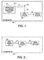
- FIG. 1 there is depicted a printing machine 100.
- charging devices, high-voltage connectors, wiring and power supplies 210 emit a radio frequency signal 211.
- the radio frequency signal 211 is received by an antenna 220 and, in turn, provided 221 to a signal detector 230.
- the signal detector 230 forms an arcing detection signal 231.
- the printing machine 100 uses the arcing detection signal 231 to determine when an arcing event has occurred based on an included method 300 or method 400.
- the signal detector 230 comprises any detecting means that is suitable for detecting the frequency and amplitude of the radio frequency signal 211.
- the signal detector 230 comprises either a high-pass filter or a band-pass filter to block all normal machine frequencies and pass only the arcing frequencies coupled with an amplitude peak-hold function.
- the antenna 220 comprises an existing wire in the harness chosen for its proximity to any likely arcing sources or else an additional antenna wire dedicated to arc signal detection.
- An included serial command bus 250 forms a serial command bus signal 251.
- the serial command bus 250 acts as an antenna to receive the radio frequency signal 211 that is depicted in FIG. 1.
- the radio frequency signal 211 is comprised in the serial command bus signal 251.
- the serial command bus signal 251 is provided to a signal detector 260.
- the signal detector 260 forms an arcing detection signal 261.
- the printing machine 100 uses the arcing detection signal 261 to determine when an arcing event has occurred based on the included method 300 or method 400.
- the signal detector 260 comprises any detecting means that is suitable for detecting the frequency and amplitude of the radio frequency signal 211 as comprised in the serial command bus signal 251.
- the signal detector 260 comprises either a high-pass filter or a band-pass filter to block all normal machine frequencies and pass only the arcing frequencies coupled with an amplitude peak-hold function.
- the printing machine 100 comprises any of a copier, a network printer and a facsimile device.
- FIG. 3 there is depicted one embodiment of a flow diagram of the method 300 of detecting an arcing event in the printing machine 100. As shown, the method or process 300 comprises the steps designated 301 through 304.
- step 301 the process forms an arcing detection signal (depicted as element 231 in FIG. 1 and depicted as element 261 in FIG. 2) that is based on the arcing event, the arcing detection signal comprising an arcing detection signal frequency value ("F arc ”) and an arcing detection signal amplitude value ("A arc ").
- F arc arcing detection signal frequency value
- a arc arcing detection signal amplitude value
- the printing machine 100 includes high-voltage apparatus 210 that generates a radio frequency signal 211 based on the arcing event and, accordingly, the step 301 of forming the arcing detection signal 231 includes detecting the radio frequency signal 211 by means of the included signal detector 230.
- the printing machine 100 includes a serial command bus 250 that provides a serial command bus signal 251 based on the arcing event and, accordingly, the step 301 of forming the arcing detection signal 261 includes detecting the serial command bus signal 251 by means of the included signal detector 260.
- step 301 the process goes to step 302.
- step 302 the process determines when an arcing event has occurred based on the arcing detection signal frequency value and the arcing detection signal amplitude value. For example, in one embodiment step 302 is similar to steps 412 and 413 which are described in connection with FIG. 4 below. The process then goes to step 303.
- step 303 the process determines an arcing level corresponding to the arcing event.
- the arcing level generally characterizes the severity of the arcing event.
- the arcing level is based on the arcing detection signal amplitude value.
- the arcing level comprises one of a group of N predetermined arcing levels, where N is an integer equal to or greater than 1.
- the group of N predetermined arcing levels comprises exactly one (1) arcing level, thus N equals 1.
- the group of N predetermined arcing levels comprises exactly two (2) arcing levels, thus N equals 2.
- the group of N predetermined arcing levels comprises exactly three (3) arcing levels, thus N equals 3.
- the group of predetermined arcing levels and corresponding arcing detection signal amplitude values are based on the functional relationship 500 that is described in connection with FIG. 5.
- the group of N predetermined arcing levels comprises four (4) or more arcing levels, thus N is equal to or greater than 4.
- step 303 After step 303, the process goes to step 304.
- step 304 the process performs at least one arcing remedy based on the arcing level determined in step 303.
- the at least one arcing remedy comprises any of logging the arcing event, generating a maintenance message, performing a maintenance procedure, informing a maintenance person, dispatching a maintenance person and powering-down the printing machine.
- the process 300 is used to diagnose arcing problems in the printing machine 100.
- the process 300 includes a preceding step 601 of enabling only a particular high-voltage (“HV”) device or group of HV devices comprised in the printing machine 100, with the remaining HV devices comprised in the printing machine being disabled.
- HV high-voltage
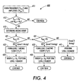
- FIG. 4 there is depicted one embodiment of a flow diagram of the method 400 of detecting an arcing event in the printing machine 100. As shown, the method or process 400 comprises the steps designated 411 through 441
- step 411 the process forms an arcing detection signal (depicted as element 231 in FIG. 1 and depicted as element 261 in FIG. 2) that is based on the arcing event, the arcing detection signal comprising an arcing detection signal frequency value ("F arc ”) and an arcing detection signal amplitude value ("A arc ").
- F arc arcing detection signal frequency value
- a arc arcing detection signal amplitude value
- the printing machine 100 includes high-voltage apparatus 210 that generates a radio frequency signal 211 based on the arcing event and, accordingly, the step 411 of forming the arcing detection signal 231 includes detecting the radio frequency signal 211 by means of the included signal detector 230.
- the printing machine 100 includes a serial command bus 250 that provides a serial command bus signal 251 based on the arcing event and, accordingly, the step 411 of forming the arcing detection signal 261 includes detecting the serial command bus signal 251 by means of the included signal detector 260.
- step 411 the process goes to step 412.
- step 412 the process determines when the arcing detection signal frequency value exceeds a predetermined arcing frequency threshold ("F 0 ”) and the arcing detection signal amplitude value exceeds a predetermined arcing amplitude threshold ("A 0 ").
- F 0 a predetermined arcing frequency threshold
- a 0 a predetermined arcing amplitude threshold
- step 413 based on the positive determination of step 412, that is, that the arcing detection signal frequency value exceeds the arcing frequency threshold and the arcing detection signal amplitude value exceeds the arcing amplitude threshold, the process determines that an arcing event has occurred. The process then goes to step 421.
- steps 421 and 431 act to determine an arcing level based on the arcing detection signal amplitude value.
- these steps 421 and 431 determine an arcing level wherein the arcing level comprises one of a group of N predetermined arcing levels, where N equals 3.
- the resulting three (3) predetermined arcing levels and their corresponding arcing detection signal amplitude values are depicted in FIG. 5.
- the arcing level is determined to be a first arcing level (depicted as "Level 1" in FIG. 5) when the step 421 determines that the arcing detection signal amplitude value ("A arc ") is less than or equal to a first threshold ("A 1 "), where the first threshold is greater than the arcing amplitude threshold ("A 0 ").
- a 1 the first threshold
- a 0 the arcing amplitude threshold
- step 421 when the step 421 determines that the arcing detection signal amplitude value is NOT less than or equal to the first threshold ("A 1 ”) and, as a result, that the arcing detection signal amplitude value exceeds the first threshold, the process goes to step 431.
- the arcing level is determined to be a second arcing level (depicted as “Level 2" in FIG. 5) when the step 431 determines that the arcing detection signal amplitude value ("A arc ") is less than or equal to a second threshold ("A 2 "), where the second threshold is greater than the first threshold ("A 1 ").
- a 2 the second threshold
- the arcing level is determined to be a third arcing level (depicted as "Level 3" in FIG. 5) when the step 431 determines that the arcing detection signal amplitude value ("A arc ”) is NOT less than or equal to the second threshold ("A 2 ”) and, as a result, that the arcing detection signal amplitude value exceeds the second threshold.
- the process then goes to step 441.
- step 421 determines the arcing level to be the first arcing level (Level 1), the process goes to step 422.
- step 422 the process forms a first level arcing event count ("C 1 ") corresponding to a count of the number of occurrences of a first level arcing event.
- C 1 first level arcing event count
- a first level arcing event is defined as an arcing event whose arcing level is determined to be the first arcing level (Level 1).
- Level 1 first level arcing event count
- step 423 the process determines when the first level arcing event count (“C 1 ”) at least equals a first level arcing event count threshold (“K 1 ”) corresponding to the first arcing level and, when it is determined that the first level arcing event count at least equals the first level arcing event count threshold, the step 423 performs at least one arcing remedy based on the first arcing level.
- the at least one arcing remedy comprises any of logging the arcing event, generating a maintenance message, performing a maintenance procedure, informing a maintenance person, dispatching a maintenance person and powering-down the printing machine.
- step 431 determines the arcing level to be the second arcing level (Level 2), the process goes to step 432.
- step 432 the process forms a second level arcing event count ("C 2 ") corresponding to a count of the number of occurrences of a second level arcing event.
- C 2 second level arcing event count
- a second level arcing event is defined as an arcing event whose arcing level is determined to be the second arcing level (Level 2).
- Level 2 the second arcing level
- step 433 the process determines when the second level arcing event count ("C 2 ") at least equals a second level arcing event count threshold ("K 2 ") corresponding to the second arcing level and, when it is determined that the second level arcing event count at least equals the second level arcing event count threshold, the step 433 performs at least one arcing remedy based on the second arcing level.
- the at least one arcing remedy comprises any of logging the arcing event, generating a maintenance message, performing a maintenance procedure, informing a maintenance person, dispatching a maintenance person and powering-down the printing machine.
- step 431 determines the arcing level to be the third arcing level (Level 3)
- a third level arcing event has occurred.
- a third level arcing event is defined as an arcing event whose arcing level is determined to be the third arcing level. The process then goes to step 441.
- the process provides at least one arcing remedy based on the third arcing level.
- the at least one arcing remedy comprises any of logging the arcing event, generating a maintenance message, performing a maintenance procedure, informing a maintenance person, dispatching a maintenance person and powering-down the printing machine.
- the process 400 is used to diagnose arcing problems in the printing machine 100.
- the process 400 includes a preceding step 601 of enabling only a particular high-voltage (“HV”) device or group of HV devices comprised in the printing machine 100, with the remaining HV devices comprised in the printing machine being disabled.
- the step 601 is described in connection with FIG. 6 below.
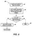
- FIG. 6 there is depicted one embodiment of a service diagnostic method 600 to diagnose arcing in the various high-voltage (“HV") devices or groups of HV devices comprised in the printing machine 100.
- the method 600 utilizes either the method 300 of FIG. 3 or the method 400 of FIG. 4.
- the method or process 600 comprises the steps designated 601 through 605.
- step 601 a first HV device or group of HV devices in the printing machine 100 is isolated, meaning that only these HV devices are enabled, with the remaining HV devices in the printing machine 100 being disabled.
- step 602 arcing is detected in the isolated HV device(s) using either method 300 or method 400 and, if needed, corrective action is performed.
- steps 603 and 604 the foregoing testing process is then repeated with respect to the remaining HV devices in the printing machine 100 until all HV devices are tested.
- the present invention automatically detects arcing by using an arcing detection signal detector circuit connected to an in-machine antenna.
- the machine CPU monitors the arcing detection signal.
- this arcing detection signal is used to activate log-only faults, while for higher levels of arcing, shutdown faults are triggered.
- the arc detector is used with a service diagnostic routine.
- the tech-rep individually enables the corona devices and notes when arcing is detected and at which levels. Arcing associated with the turn-on of a specific device indicates a problem in that device or associated wiring or power supply. To save time it is possible to half-split the devices by turning on half the total charging devices and then half again depending on the arcing result.
- These routines can be manual in operation or else automated in software. Also, these routines can be run periodically, or at every cycle up, or only as a manual diagnostic routine by the tech-rep.
- the signal detector 230 comprises an RF amplifier circuit with a high-frequency pass band well above any normal machine frequencies.
- the signal detector 230 can include a peak-hold function, enabling only periodic monitoring by the CPU of the signal.
- a VHF (50-450 MHz) amplifier is connected to an antenna wire positioned in the power supply area of the print engine.
- the amplifier output is connected to a diode and a capacitor to rectify and peak-hold the signal. Arcing events are induced and the resulting signal is captured on a digital oscilloscope and displayed for analysis.
- One advantage of the present invention is that it enables the service time and effort required to diagnose arcing in the printing machine to be substantially reduced.
- the present invention thereby enables quick isolation of the corresponding defective wiring, parts, or connectors.
- one key business advantage of the present invention is that it substantially reduces both the quantity and duration of the printing machine down times.
- Another key business advantage of the present invention is that it results in substantially simpler and therefore less expensive service calls by maintenance personnel. Both of these business advantages, of course, translate into increased productivity of the printing machine itself.
- the invention thereby enables the printing machine user to decrease its corresponding production costs, thus translating into higher profit levels for the user's printing service.
- the method 300 of detecting an arcing event in a printing machine 100 comprising (a) in step 301, forming an arcing detection signal that is based on the arcing event, the arcing detection signal comprising an arcing detection signal frequency value ("F arc ”) and an arcing detection signal amplitude value ("A arc "); (b) in step 302, determining when an arcing event has occurred based on the arcing detection signal frequency value and the arcing detection signal amplitude value; (c) in step 303, determining an arcing level corresponding to the arcing event; and (d) in step 304, performing at least one arcing remedy based on the arcing level.
- the second aspect of the invention namely, the method 400 of detecting an arcing event in a printing machine 100, the method comprising (a) in step 411, forming an arcing detection signal (any of elements 231 and 261) that is based on the arcing event, the arcing detection signal comprising an arcing detection signal frequency value ("F arc ”) and an arcing detection signal amplitude value ("A arc "); (b) in step 412, determining when the arcing detection signal frequency value exceeds a predetermined arcing frequency threshold ("F 0 ”) and the arcing detection signal amplitude value exceeds a predetermined arcing amplitude threshold ("A 0 "); and (c) in step 413, when the arcing detection signal frequency value exceeds the arcing frequency threshold and the arcing detection signal amplitude value exceeds the arcing amplitude threshold, determining that an arcing event has occurred.
- an arcing detection signal any of elements 231 and 261
Landscapes
- Physics & Mathematics (AREA)
- Electromagnetism (AREA)
- General Physics & Mathematics (AREA)
- Accessory Devices And Overall Control Thereof (AREA)
- Control Or Security For Electrophotography (AREA)
- Inking, Control Or Cleaning Of Printing Machines (AREA)
Abstract
A printing machine (100) is arranged to detect an arcing event. An arcing detection signal (231) based on the arcing event is formed. The arcing detection signal includes an arcing detection signal frequency and an arcing detection signal amplitude. The arcing detection signal frequency value and the arcing detection signal amplitude value are used to detect the occurrence of an arcing event. Once an arcing event is detected, an arcing level corresponding to the severity of the arcing event is determined. At least one arcing remedy based on the arcing level then is performed. The arcing remedy comprises any of logging the arcing event, generating a maintenance message, performing a maintenance procedure, informing a maintenance person, dispatching a maintenance person and powering-down the printing machine.
Description
- Modern printing machines such as "iGen" can have a high rate of spurious corona or "arcing" induced faults. Arcing generates radio frequency ("RF") noise that can couple into machine signals and interfere with machine logic and control systems. Spurious discharges associated with the corona charging systems radiate RF from the fast rise/fall times of the associated currents. Arcing can occur in the charging device (dicorotron) but is more troublesome in the high-voltage ("HV") connectors, wiring and associated power supplies. For example, in iGen there are 11 separate HV supplies feeding 18 corona devices. Further, radiated RF noise can result in communication faults or machine clock timing errors. Timing errors can cause process controls patch read errors and associated color shifts or faults.
- Diagnosing arcing problems is currently difficult due to the large number of HV wires and connectors in iGen. Many of these wires and connectors are difficult to see or access for troubleshooting purposes. As a result, it is not uncommon for a machine with arcing problems to have long service calls lasting several days. Moreover, many perfectly good parts are replaced in an attempt to isolate the arcing problem and fix the machine.
- Furthermore, as machine parts age, "grounding" brushes can wear out which, in turn, will allow associated parts to charge up and arc. These failures are usually intermittent and frustrating to diagnose.
- Possible machine arcing sources are listed as follows: corona devices; HV connectors; breakdown around HV wiring; intermittent bias brush connections to cleaner brushes; intermittent bias brush connections to developer rolls; arcing in toner waste systems, including ducts, manifolds, waste bottles, cyclone separators, etc.; paper path components; and arcing in the developer system, including toner charging of conductive, electrically-isolated development system components.
- In accordance with the present invention, we provide a printing machine and method of detecting an arcing event in a printing machine, the method comprising:
- (a) forming an arcing detection signal that is based on the arcing event, the arcing detection signal comprising an arcing detection signal frequency value and an arcing detection signal amplitude value;
- (b) determining when an arcing event has occurred based on the arcing detection signal frequency value and the arcing detection signal amplitude value; and,
- (c) determining an arcing level corresponding to the arcing event.
- Some examples of printing machines and methods according to the present invention will now be described with reference to the accompanying drawings, in which:-
- FIG. 1 depicts a
printing machine 100 arranged to form anarcing detection signal 231 based on aradio frequency signal 211. Thearcing detection signal 231 is then used to detect an arcing event based on an includedmethod 300 ormethod 400. - FIG. 2 depicts the
printing machine 100 arranged to form anarcing detection signal 261 based on a serialcommand bus signal 251. Thearcing detection signal 261 is then used to detect an arcing event based on an includedmethod 300 ormethod 400. - FIG. 3 depicts one embodiment of a flow diagram of the
method 300 of detecting an arcing event in theprinting machine 100. - FIG. 4 depicts one embodiment of a flow diagram of the
method 400 of detecting an arcing event in theprinting machine 100. - FIG. 5 depicts one embodiment of a functional relationship 500 of arcing detection signal amplitude values and corresponding arcing levels that is used with the
method 400 and is also optionally used with themethod 300. As shown, the arcing detection signal amplitude values are plotted on the horizontal or "X" axis. Also, the corresponding arcing levels are plotted on the vertical or "Y" axis. As shown, each arcing level on the Y axis comprises one of a group of N predetermined arcing levels, where N equals 3. Thus, the functional relationship 500 comprises exactly three (3) arcing levels designated "Level 1 ", "Level 2" and "Level 3". Note that arcing levels are defined only for those arcing detection signal amplitude values that are greater than A0. - FIG. 6 depicts one embodiment of a service
diagnostic method 600 to diagnose arcing in the various high-voltage ("HV") devices or groups of HV devices comprised in theprinting machine 100. Themethod 600 utilizes either themethod 300 or themethod 400. - Briefly, a printing machine is arranged to detect an arcing event. An arcing detection signal based on the arcing event is formed. The arcing detection signal includes an arcing detection signal frequency and an arcing detection signal amplitude. The arcing detection signal frequency value and the arcing detection signal amplitude value are used to detect the occurrence of an arcing event. Once an arcing event is detected, an arcing level corresponding to the severity of the arcing event is determined. At least one arcing remedy based on the arcing level then is performed. The arcing remedy comprises any of logging the arcing event, generating a maintenance message, performing a maintenance procedure, informing a maintenance person, dispatching a maintenance person and powering-down the printing machine. In one embodiment, the method is used to diagnose arcing problems in the printing machine.
- Referring now to FIG. 1, there is depicted a
printing machine 100. Included charging devices, high-voltage connectors, wiring andpower supplies 210 emit aradio frequency signal 211. Theradio frequency signal 211 is received by anantenna 220 and, in turn, provided 221 to asignal detector 230. Thesignal detector 230, in turn, forms anarcing detection signal 231. Theprinting machine 100 uses thearcing detection signal 231 to determine when an arcing event has occurred based on an includedmethod 300 ormethod 400. - Referring still to FIG. 1, in one embodiment, the
signal detector 230 comprises any detecting means that is suitable for detecting the frequency and amplitude of theradio frequency signal 211. In one embodiment, thesignal detector 230 comprises either a high-pass filter or a band-pass filter to block all normal machine frequencies and pass only the arcing frequencies coupled with an amplitude peak-hold function. In one embodiment, theantenna 220 comprises an existing wire in the harness chosen for its proximity to any likely arcing sources or else an additional antenna wire dedicated to arc signal detection. - Referring now to FIG. 2, there is depicted the FIG. 1
printing machine 100. An includedserial command bus 250 forms a serialcommand bus signal 251. Theserial command bus 250 acts as an antenna to receive theradio frequency signal 211 that is depicted in FIG. 1. As a result, theradio frequency signal 211 is comprised in the serialcommand bus signal 251. The serialcommand bus signal 251 is provided to asignal detector 260. Thesignal detector 260, in turn, forms anarcing detection signal 261. Theprinting machine 100 uses thearcing detection signal 261 to determine when an arcing event has occurred based on the includedmethod 300 ormethod 400. - Referring still to FIG. 2, in one embodiment, the
signal detector 260 comprises any detecting means that is suitable for detecting the frequency and amplitude of theradio frequency signal 211 as comprised in the serialcommand bus signal 251. In one embodiment, thesignal detector 260 comprises either a high-pass filter or a band-pass filter to block all normal machine frequencies and pass only the arcing frequencies coupled with an amplitude peak-hold function. - Referring now generally to FIGS. 1 and 2, in various embodiments the
printing machine 100 comprises any of a copier, a network printer and a facsimile device. - Referring now to FIG. 3, there is depicted one embodiment of a flow diagram of the
method 300 of detecting an arcing event in theprinting machine 100. As shown, the method orprocess 300 comprises the steps designated 301 through 304. - The process starts at
step 301. Instep 301, the process forms an arcing detection signal (depicted aselement 231 in FIG. 1 and depicted aselement 261 in FIG. 2) that is based on the arcing event, the arcing detection signal comprising an arcing detection signal frequency value ("Farc") and an arcing detection signal amplitude value ("Aarc"). - Still referring to
step 301, with momentary cross-reference to FIG. 1, in one embodiment theprinting machine 100 includes high-voltage apparatus 210 that generates aradio frequency signal 211 based on the arcing event and, accordingly, thestep 301 of forming thearcing detection signal 231 includes detecting theradio frequency signal 211 by means of the includedsignal detector 230. - Still referring to
step 301, with momentary cross-reference to FIG. 2, in one embodiment theprinting machine 100 includes aserial command bus 250 that provides a serialcommand bus signal 251 based on the arcing event and, accordingly, thestep 301 of forming thearcing detection signal 261 includes detecting the serialcommand bus signal 251 by means of the includedsignal detector 260. - After
step 301, the process goes to step 302. - In
step 302, the process determines when an arcing event has occurred based on the arcing detection signal frequency value and the arcing detection signal amplitude value. For example, in oneembodiment step 302 is similar tosteps - In
step 303, the process determines an arcing level corresponding to the arcing event. The arcing level generally characterizes the severity of the arcing event. - Still referring to step 303, in one embodiment, for example, the arcing level is based on the arcing detection signal amplitude value.
- In one embodiment, the arcing level comprises one of a group of N predetermined arcing levels, where N is an integer equal to or greater than 1.
- In one embodiment, the group of N predetermined arcing levels comprises exactly one (1) arcing level, thus N equals 1.
- In one embodiment, the group of N predetermined arcing levels comprises exactly two (2) arcing levels, thus N equals 2.
- In one embodiment, the group of N predetermined arcing levels comprises exactly three (3) arcing levels, thus N equals 3. For example, in one embodiment the group of predetermined arcing levels and corresponding arcing detection signal amplitude values are based on the functional relationship 500 that is described in connection with FIG. 5.
- Still referring to step 303, in one embodiment the group of N predetermined arcing levels comprises four (4) or more arcing levels, thus N is equal to or greater than 4.
- After
step 303, the process goes to step 304. - In
step 304, the process performs at least one arcing remedy based on the arcing level determined instep 303. In various embodiments of thestep 304, the at least one arcing remedy comprises any of logging the arcing event, generating a maintenance message, performing a maintenance procedure, informing a maintenance person, dispatching a maintenance person and powering-down the printing machine. - Referring generally to FIG. 3, in one embodiment the
process 300 is used to diagnose arcing problems in theprinting machine 100. In this embodiment, with momentary cross-reference to FIG. 6, theprocess 300 includes a precedingstep 601 of enabling only a particular high-voltage ("HV") device or group of HV devices comprised in theprinting machine 100, with the remaining HV devices comprised in the printing machine being disabled. Thestep 601 is described in connection with FIG. 6 below. - Referring now to FIG. 4, there is depicted one embodiment of a flow diagram of the
method 400 of detecting an arcing event in theprinting machine 100. As shown, the method orprocess 400 comprises the steps designated 411 through 441 - The process starts at
step 411. Instep 411, the process forms an arcing detection signal (depicted aselement 231 in FIG. 1 and depicted aselement 261 in FIG. 2) that is based on the arcing event, the arcing detection signal comprising an arcing detection signal frequency value ("Farc") and an arcing detection signal amplitude value ("Aarc"). - Still referring to step 411, with momentary cross-reference to FIG. 1, in one embodiment the
printing machine 100 includes high-voltage apparatus 210 that generates aradio frequency signal 211 based on the arcing event and, accordingly, thestep 411 of forming the arcingdetection signal 231 includes detecting theradio frequency signal 211 by means of the includedsignal detector 230. - Still referring to step 411, with momentary cross-reference to FIG. 2, in one embodiment the
printing machine 100 includes aserial command bus 250 that provides a serialcommand bus signal 251 based on the arcing event and, accordingly, thestep 411 of forming the arcingdetection signal 261 includes detecting the serialcommand bus signal 251 by means of the includedsignal detector 260. - After
step 411, the process goes to step 412. - In
step 412 the process determines when the arcing detection signal frequency value exceeds a predetermined arcing frequency threshold ("F0") and the arcing detection signal amplitude value exceeds a predetermined arcing amplitude threshold ("A0"). When the result of this determination is positive (depicted as "YES" in step 412), the process goes to step 413. - In
step 413, based on the positive determination ofstep 412, that is, that the arcing detection signal frequency value exceeds the arcing frequency threshold and the arcing detection signal amplitude value exceeds the arcing amplitude threshold, the process determines that an arcing event has occurred. The process then goes to step 421. - Referring generally to
steps steps steps - Referring to step 421, with cross-reference to FIG. 5, the arcing level is determined to be a first arcing level (depicted as "
Level 1" in FIG. 5) when thestep 421 determines that the arcing detection signal amplitude value ("Aarc") is less than or equal to a first threshold ("A1"), where the first threshold is greater than the arcing amplitude threshold ("A0"). For good understanding ofstep 421, recall that theprevious step 412 already has determined that the arcing detection signal amplitude value ("Aarc") exceeds the predetermined arcing amplitude threshold ("A0"). The process then goes to step 422. - Still referring to step 421, when the
step 421 determines that the arcing detection signal amplitude value is NOT less than or equal to the first threshold ("A1") and, as a result, that the arcing detection signal amplitude value exceeds the first threshold, the process goes to step 431. - In
step 431, the arcing level is determined to be a second arcing level (depicted as "Level 2" in FIG. 5) when thestep 431 determines that the arcing detection signal amplitude value ("Aarc") is less than or equal to a second threshold ("A2"), where the second threshold is greater than the first threshold ("A1"). The process then goes to step 432. - Still referring to step 431, the arcing level is determined to be a third arcing level (depicted as "
Level 3" in FIG. 5) when thestep 431 determines that the arcing detection signal amplitude value ("Aarc") is NOT less than or equal to the second threshold ("A2") and, as a result, that the arcing detection signal amplitude value exceeds the second threshold. The process then goes to step 441. - Returning to step 421, when
step 421 determines the arcing level to be the first arcing level (Level 1), the process goes to step 422. - In
step 422, the process forms a first level arcing event count ("C1") corresponding to a count of the number of occurrences of a first level arcing event. For good understanding, a first level arcing event is defined as an arcing event whose arcing level is determined to be the first arcing level (Level 1). The process then goes to step 423. - In
step 423, the process determines when the first level arcing event count ("C1") at least equals a first level arcing event count threshold ("K1") corresponding to the first arcing level and, when it is determined that the first level arcing event count at least equals the first level arcing event count threshold, thestep 423 performs at least one arcing remedy based on the first arcing level. In one embodiment, the at least one arcing remedy comprises any of logging the arcing event, generating a maintenance message, performing a maintenance procedure, informing a maintenance person, dispatching a maintenance person and powering-down the printing machine. - Returning to step 431, when
step 431 determines the arcing level to be the second arcing level (Level 2), the process goes to step 432. - In
step 432, the process forms a second level arcing event count ("C2") corresponding to a count of the number of occurrences of a second level arcing event. For good understanding, a second level arcing event is defined as an arcing event whose arcing level is determined to be the second arcing level (Level 2). The process then goes to step 433. - In
step 433, the process determines when the second level arcing event count ("C2") at least equals a second level arcing event count threshold ("K2") corresponding to the second arcing level and, when it is determined that the second level arcing event count at least equals the second level arcing event count threshold, thestep 433 performs at least one arcing remedy based on the second arcing level. In one embodiment, the at least one arcing remedy comprises any of logging the arcing event, generating a maintenance message, performing a maintenance procedure, informing a maintenance person, dispatching a maintenance person and powering-down the printing machine. - Returning to step 431, when
step 431 determines the arcing level to be the third arcing level (Level 3), then a third level arcing event has occurred. For good understanding, a third level arcing event is defined as an arcing event whose arcing level is determined to be the third arcing level. The process then goes to step 441. - In
step 441, the process provides at least one arcing remedy based on the third arcing level. In one embodiment, the at least one arcing remedy comprises any of logging the arcing event, generating a maintenance message, performing a maintenance procedure, informing a maintenance person, dispatching a maintenance person and powering-down the printing machine. - Referring generally to FIG. 4, in one embodiment the
process 400 is used to diagnose arcing problems in theprinting machine 100. In this embodiment, with momentary cross-reference to FIG. 6, theprocess 400 includes a precedingstep 601 of enabling only a particular high-voltage ("HV") device or group of HV devices comprised in theprinting machine 100, with the remaining HV devices comprised in the printing machine being disabled. Thestep 601 is described in connection with FIG. 6 below. - Referring now to FIG. 6, there is depicted one embodiment of a service
diagnostic method 600 to diagnose arcing in the various high-voltage ("HV") devices or groups of HV devices comprised in theprinting machine 100. Themethod 600 utilizes either themethod 300 of FIG. 3 or themethod 400 of FIG. 4. - As shown, the method or
process 600 comprises the steps designated 601 through 605. - In
step 601, a first HV device or group of HV devices in theprinting machine 100 is isolated, meaning that only these HV devices are enabled, with the remaining HV devices in theprinting machine 100 being disabled. - In
step 602, arcing is detected in the isolated HV device(s) using eithermethod 300 ormethod 400 and, if needed, corrective action is performed. - In
steps printing machine 100 until all HV devices are tested. - The testing is then complete,
step 605. - In one embodiment, the present invention automatically detects arcing by using an arcing detection signal detector circuit connected to an in-machine antenna. The machine CPU monitors the arcing detection signal. In one embodiment, for low (harmless) levels of arcing, this arcing detection signal is used to activate log-only faults, while for higher levels of arcing, shutdown faults are triggered.
- In one embodiment, the arc detector is used with a service diagnostic routine. In this embodiment, the tech-rep individually enables the corona devices and notes when arcing is detected and at which levels. Arcing associated with the turn-on of a specific device indicates a problem in that device or associated wiring or power supply. To save time it is possible to half-split the devices by turning on half the total charging devices and then half again depending on the arcing result. These routines can be manual in operation or else automated in software. Also, these routines can be run periodically, or at every cycle up, or only as a manual diagnostic routine by the tech-rep.
- Referring again to FIG. 1, in one embodiment, the
signal detector 230 comprises an RF amplifier circuit with a high-frequency pass band well above any normal machine frequencies. Thesignal detector 230 can include a peak-hold function, enabling only periodic monitoring by the CPU of the signal. - In one embodiment of the present invention, a VHF (50-450 MHz) amplifier is connected to an antenna wire positioned in the power supply area of the print engine. The amplifier output is connected to a diode and a capacitor to rectify and peak-hold the signal. Arcing events are induced and the resulting signal is captured on a digital oscilloscope and displayed for analysis.
- Some advantages of the present invention are now discussed. One advantage of the present invention is that it enables the service time and effort required to diagnose arcing in the printing machine to be substantially reduced. Thus, by automatically detecting an arcing condition in the printing machine, the present invention thereby enables quick isolation of the corresponding defective wiring, parts, or connectors. Accordingly, one key business advantage of the present invention is that it substantially reduces both the quantity and duration of the printing machine down times. Another key business advantage of the present invention is that it results in substantially simpler and therefore less expensive service calls by maintenance personnel. Both of these business advantages, of course, translate into increased productivity of the printing machine itself. Moreover, by increasing the productivity of the printing machine, the invention thereby enables the printing machine user to decrease its corresponding production costs, thus translating into higher profit levels for the user's printing service.
- Thus, there has been described the first aspect of the invention, namely, the
method 300 of detecting an arcing event in aprinting machine 100, the method comprising (a) instep 301, forming an arcing detection signal that is based on the arcing event, the arcing detection signal comprising an arcing detection signal frequency value ("Farc") and an arcing detection signal amplitude value ("Aarc"); (b) instep 302, determining when an arcing event has occurred based on the arcing detection signal frequency value and the arcing detection signal amplitude value; (c) instep 303, determining an arcing level corresponding to the arcing event; and (d) instep 304, performing at least one arcing remedy based on the arcing level. - Also, there has been described the second aspect of the invention, namely, the
method 400 of detecting an arcing event in aprinting machine 100, the method comprising (a) instep 411, forming an arcing detection signal (any ofelements 231 and 261) that is based on the arcing event, the arcing detection signal comprising an arcing detection signal frequency value ("Farc") and an arcing detection signal amplitude value ("Aarc"); (b) instep 412, determining when the arcing detection signal frequency value exceeds a predetermined arcing frequency threshold ("F0") and the arcing detection signal amplitude value exceeds a predetermined arcing amplitude threshold ("A0"); and (c) instep 413, when the arcing detection signal frequency value exceeds the arcing frequency threshold and the arcing detection signal amplitude value exceeds the arcing amplitude threshold, determining that an arcing event has occurred.
Claims (12)
- A method of detecting an arcing event in a printing machine, the method comprising:(a) forming an arcing detection signal that is based on the arcing event, the arcing detection signal comprising an arcing detection signal frequency value and an arcing detection signal amplitude value;(b) determining when an arcing event has occurred based on the arcing detection signal frequency value and the arcing detection signal amplitude value; and,(c) determining an arcing level corresponding to the arcing event.
- A method according to claim 1, wherein steps (b) and (c) comprise determining when the arcing detection signal frequency value exceeds a predetermined arcing frequency threshold and the arcing detection signal amplitude value exceeds a predetermined arcing amplitude threshold; and when the arcing detection signal frequency value exceeds the arcing frequency threshold and the arcing detection signal amplitude value exceeds the arcing amplitude threshold, determining that an arcing event has occurred.
- The method of claim 1 or claim 2, including determining an arcing level based on the arcing detection signal amplitude value.
- The method of claim 2, where the arcing level comprises one of a group of N predetermined arcing levels, where N is an integer equal to or greater than 1.
- A method according to any of the preceding claims, further comprising:(d) performing at least one arcing remedy.
- The method of claim 5, when dependent on claim 3 or claim 4, including performing at least one arcing remedy based on the arcing level.
- The method of claim 5 or claim 6, the at least one arcing remedy comprising any of logging the arcing event, generating a maintenance message, performing a maintenance procedure, informing a maintenance person, dispatching a maintenance person and powering-down the printing machine.
- The method of any of the preceding claims, the printing machine including high-voltage apparatus that generates a radio frequency signal based on the arcing event, the step (a) of forming the arcing detection signal including a step of detecting the radio frequency signal.
- The method of any of claims 1 to 7, the printing machine including a serial command bus that provides a serial command bus signal based on the arcing event, the step (a) of forming the arcing detection signal including a step of detecting the serial command bus signal.
- The method of any of the preceding claims, including a preceding step of enabling only a particular high-voltage ("HV") device or group of HV devices comprised in the printing machine, with the remaining HV devices comprised in the printing machine being disabled.
- A printing machine adapted to perform a method according to any of the preceding claims.
- A printing machine according to claim 11, the printing machine comprising one of a copier, a network printer and a facsimile device.
Applications Claiming Priority (1)
| Application Number | Priority Date | Filing Date | Title |
|---|---|---|---|
| US10/924,045 US20060038574A1 (en) | 2004-08-23 | 2004-08-23 | Method of detecting an arcing event and a printing machine arranged with the same |
Publications (1)
| Publication Number | Publication Date |
|---|---|
| EP1630565A1 true EP1630565A1 (en) | 2006-03-01 |
Family
ID=35385022
Family Applications (1)
| Application Number | Title | Priority Date | Filing Date |
|---|---|---|---|
| EP05255061A Withdrawn EP1630565A1 (en) | 2004-08-23 | 2005-08-16 | A method of detecting an arcing event and a printing machine using said method |
Country Status (4)
| Country | Link |
|---|---|
| US (1) | US20060038574A1 (en) |
| EP (1) | EP1630565A1 (en) |
| JP (1) | JP2006056255A (en) |
| BR (1) | BRPI0503736A (en) |
Cited By (1)
| Publication number | Priority date | Publication date | Assignee | Title |
|---|---|---|---|---|
| US8199343B2 (en) | 2006-11-07 | 2012-06-12 | Xerox Corporation | Partial electrical discharge system and method |
Families Citing this family (3)
| Publication number | Priority date | Publication date | Assignee | Title |
|---|---|---|---|---|
| US8076943B2 (en) * | 2008-02-21 | 2011-12-13 | Genesis Medical Imaging, Inc. | Impedance-based arc detector for computed tomography scanner and method of use thereof |
| CN107064673A (en) * | 2017-03-30 | 2017-08-18 | 上海理工大学 | Electric arc detecting device and double-fed wind power generator electric brush slip ring protection system |
| CN110605924B (en) * | 2019-08-31 | 2021-03-30 | 森大(深圳)技术有限公司 | Printer stability continuous test method, storage medium, equipment and printer |
Citations (6)
| Publication number | Priority date | Publication date | Assignee | Title |
|---|---|---|---|---|
| US4631473A (en) * | 1981-09-07 | 1986-12-23 | Nippon Univac Kaisha, Ltd. | Transient electromagnetic field detector |
| US5123102A (en) * | 1988-12-19 | 1992-06-16 | Hewlett-Packard Company | Method and apparatus for suspending computation due to detection of electrostatic discharge |
| US5541721A (en) * | 1994-12-14 | 1996-07-30 | Xerox Corporation | System for controlling electrostatic voltmeters in a tri-level highlight color xerographic printer |
| US5903220A (en) * | 1997-04-17 | 1999-05-11 | Lucent Technologies Inc. | Electrostatic discharge event detector |
| JPH11223647A (en) * | 1998-02-06 | 1999-08-17 | Ricoh Co Ltd | An electromagnetic noise measurement device using a near-field probe. |
| EP1060895A1 (en) * | 1999-06-16 | 2000-12-20 | Eastman Kodak Company | A printer and method adapted to sense data of a consumable loaded into the printer |
Family Cites Families (6)
| Publication number | Priority date | Publication date | Assignee | Title |
|---|---|---|---|---|
| US3943502A (en) * | 1975-02-07 | 1976-03-09 | Wood Industries, Inc. | Printing machine high voltage power system |
| CA2128676C (en) * | 1993-09-08 | 1997-12-23 | John D. Sotack | Capacitive sensor |
| US5691869A (en) * | 1995-06-06 | 1997-11-25 | Eaton Corporation | Low cost apparatus for detecting arcing faults and circuit breaker incorporating same |
| IL135120A0 (en) * | 2000-03-16 | 2001-05-20 | Sapir Michael | Apparatus for the detection and early warning of electrical arcing fault |
| US6374075B1 (en) * | 2000-04-28 | 2002-04-16 | Xerox Corporation | Printing systems and methods |
| US6734682B2 (en) * | 2002-03-05 | 2004-05-11 | Eaton Corporation | Testing device for detecting and locating arc faults in an electrical system |
-
2004
- 2004-08-23 US US10/924,045 patent/US20060038574A1/en not_active Abandoned
-
2005
- 2005-08-16 JP JP2005235675A patent/JP2006056255A/en not_active Withdrawn
- 2005-08-16 EP EP05255061A patent/EP1630565A1/en not_active Withdrawn
- 2005-08-23 BR BRPI0503736-0A patent/BRPI0503736A/en not_active Application Discontinuation
Patent Citations (6)
| Publication number | Priority date | Publication date | Assignee | Title |
|---|---|---|---|---|
| US4631473A (en) * | 1981-09-07 | 1986-12-23 | Nippon Univac Kaisha, Ltd. | Transient electromagnetic field detector |
| US5123102A (en) * | 1988-12-19 | 1992-06-16 | Hewlett-Packard Company | Method and apparatus for suspending computation due to detection of electrostatic discharge |
| US5541721A (en) * | 1994-12-14 | 1996-07-30 | Xerox Corporation | System for controlling electrostatic voltmeters in a tri-level highlight color xerographic printer |
| US5903220A (en) * | 1997-04-17 | 1999-05-11 | Lucent Technologies Inc. | Electrostatic discharge event detector |
| JPH11223647A (en) * | 1998-02-06 | 1999-08-17 | Ricoh Co Ltd | An electromagnetic noise measurement device using a near-field probe. |
| EP1060895A1 (en) * | 1999-06-16 | 2000-12-20 | Eastman Kodak Company | A printer and method adapted to sense data of a consumable loaded into the printer |
Non-Patent Citations (2)
| Title |
|---|
| ANONYMOUS: "Electrostatic Discharge Monitor. November 1980.", IBM TECHNICAL DISCLOSURE BULLETIN, vol. 23, no. 6, 1 November 1980 (1980-11-01), New York, US, pages 2555, XP002356303 * |
| PATENT ABSTRACTS OF JAPAN vol. 1999, no. 13 30 November 1999 (1999-11-30) * |
Cited By (1)
| Publication number | Priority date | Publication date | Assignee | Title |
|---|---|---|---|---|
| US8199343B2 (en) | 2006-11-07 | 2012-06-12 | Xerox Corporation | Partial electrical discharge system and method |
Also Published As
| Publication number | Publication date |
|---|---|
| US20060038574A1 (en) | 2006-02-23 |
| JP2006056255A (en) | 2006-03-02 |
| BRPI0503736A (en) | 2006-04-18 |
Similar Documents
| Publication | Publication Date | Title |
|---|---|---|
| US7649470B2 (en) | Method and apparatus for detection of brush sparking and spark erosion on electrical machines | |
| EP3182114A1 (en) | Partial discharge monitoring of electrical machines using acoustic emission sensors and electrical sensors | |
| CN1695065B (en) | Method and device for detecting brush ignition and spark corrosion in electric motors | |
| JP7107632B2 (en) | Rotating machine diagnostic system and rotating machine diagnostic method | |
| CN109541431A (en) | The voltage level of integrated circuit for production test and debugging monitors | |
| KR102148618B1 (en) | Device and system for diagnosing power cable, and method for diagnosing power calbe using the same | |
| CN111999620A (en) | Multi-channel joint positioning method for partial discharge of power equipment | |
| EP2750258B1 (en) | Methods for locating ground faults and insulation degradation condition in energy conversion systems | |
| Huecker et al. | UHF partial discharge monitoring and expert system diagnosis | |
| US20060038574A1 (en) | Method of detecting an arcing event and a printing machine arranged with the same | |
| CN111562466A (en) | Detection method for partial discharge of stator winding of large hydraulic generator | |
| KR20210139042A (en) | Partial Discharge Pattern Analysis Method and Device for HVDC cables | |
| CN111175609A (en) | Power distribution network line fault positioning method and system | |
| US8199343B2 (en) | Partial electrical discharge system and method | |
| Gorgan et al. | Monitoring and Diagnosis of Electrical Equipment Insulation with the Support of Combined Conventional and Alternative Partial Discharge Methods | |
| CN116131214B (en) | Network management system of digital harmonic elimination device and use method thereof | |
| Van Breen et al. | Standardization of on-line VHF PD measurements on turbo generators | |
| CN113866671B (en) | A method, system, implementation method and device for monitoring server voltage leakage | |
| CN113037022A (en) | Phase modifier large shaft protection method and device | |
| Stone et al. | Comparison of low and high frequency partial discharge measurements on stator windings | |
| US20200264073A1 (en) | Method for monitoring rolling bearings | |
| CN115296251B (en) | An arc light unit | |
| RU2818652C1 (en) | Method for diagnostics of cable power transmission line and device for its implementation | |
| JPH0530223B2 (en) | ||
| CN112771393A (en) | AFCI self-check |
Legal Events
| Date | Code | Title | Description |
|---|---|---|---|
| PUAI | Public reference made under article 153(3) epc to a published international application that has entered the european phase |
Free format text: ORIGINAL CODE: 0009012 |
|
| AK | Designated contracting states |
Kind code of ref document: A1 Designated state(s): AT BE BG CH CY CZ DE DK EE ES FI FR GB GR HU IE IS IT LI LT LU LV MC NL PL PT RO SE SI SK TR |
|
| AX | Request for extension of the european patent |
Extension state: AL BA HR MK YU |
|
| AKX | Designation fees paid | ||
| REG | Reference to a national code |
Ref country code: DE Ref legal event code: 8566 |
|
| STAA | Information on the status of an ep patent application or granted ep patent |
Free format text: STATUS: THE APPLICATION IS DEEMED TO BE WITHDRAWN |
|
| 18D | Application deemed to be withdrawn |
Effective date: 20060902 |