EP1630501A1 - Refrigerator - Google Patents
Refrigerator Download PDFInfo
- Publication number
- EP1630501A1 EP1630501A1 EP05253296A EP05253296A EP1630501A1 EP 1630501 A1 EP1630501 A1 EP 1630501A1 EP 05253296 A EP05253296 A EP 05253296A EP 05253296 A EP05253296 A EP 05253296A EP 1630501 A1 EP1630501 A1 EP 1630501A1
- Authority
- EP
- European Patent Office
- Prior art keywords
- refrigerator
- main body
- corners
- height adjustable
- adjustable legs
- Prior art date
- Legal status (The legal status is an assumption and is not a legal conclusion. Google has not performed a legal analysis and makes no representation as to the accuracy of the status listed.)
- Withdrawn
Links
Images


Classifications
-
- F—MECHANICAL ENGINEERING; LIGHTING; HEATING; WEAPONS; BLASTING
- F25—REFRIGERATION OR COOLING; COMBINED HEATING AND REFRIGERATION SYSTEMS; HEAT PUMP SYSTEMS; MANUFACTURE OR STORAGE OF ICE; LIQUEFACTION SOLIDIFICATION OF GASES
- F25D—REFRIGERATORS; COLD ROOMS; ICE-BOXES; COOLING OR FREEZING APPARATUS NOT OTHERWISE PROVIDED FOR
- F25D23/00—General constructional features
-
- F—MECHANICAL ENGINEERING; LIGHTING; HEATING; WEAPONS; BLASTING
- F25—REFRIGERATION OR COOLING; COMBINED HEATING AND REFRIGERATION SYSTEMS; HEAT PUMP SYSTEMS; MANUFACTURE OR STORAGE OF ICE; LIQUEFACTION SOLIDIFICATION OF GASES
- F25D—REFRIGERATORS; COLD ROOMS; ICE-BOXES; COOLING OR FREEZING APPARATUS NOT OTHERWISE PROVIDED FOR
- F25D23/00—General constructional features
- F25D23/02—Doors; Covers
-
- F—MECHANICAL ENGINEERING; LIGHTING; HEATING; WEAPONS; BLASTING
- F25—REFRIGERATION OR COOLING; COMBINED HEATING AND REFRIGERATION SYSTEMS; HEAT PUMP SYSTEMS; MANUFACTURE OR STORAGE OF ICE; LIQUEFACTION SOLIDIFICATION OF GASES
- F25D—REFRIGERATORS; COLD ROOMS; ICE-BOXES; COOLING OR FREEZING APPARATUS NOT OTHERWISE PROVIDED FOR
- F25D2323/00—General constructional features not provided for in other groups of this subclass
- F25D2323/0011—Means for leveling refrigerators
-
- F—MECHANICAL ENGINEERING; LIGHTING; HEATING; WEAPONS; BLASTING
- F25—REFRIGERATION OR COOLING; COMBINED HEATING AND REFRIGERATION SYSTEMS; HEAT PUMP SYSTEMS; MANUFACTURE OR STORAGE OF ICE; LIQUEFACTION SOLIDIFICATION OF GASES
- F25D—REFRIGERATORS; COLD ROOMS; ICE-BOXES; COOLING OR FREEZING APPARATUS NOT OTHERWISE PROVIDED FOR
- F25D2400/00—General features of, or devices for refrigerators, cold rooms, ice-boxes, or for cooling or freezing apparatus not covered by any other subclass
- F25D2400/38—Refrigerating devices characterised by wheels
Definitions
- the present invention relates to refrigerators.
- a refrigerator serves to store various foods in a fresh state for a long time by supplying cold air, generated from an evaporator, to storage chambers, such as a chilling chamber and a freezing chamber.
- storage chambers such as a chilling chamber and a freezing chamber.
- refrigerators having a large volume for storing a large quantity of foods have been manufactured and sold.
- Such a refrigerator having a large volume includes a main body, the front surface of which is opened, a chilling chamber and a freezing chamber divided by a partition vertically disposed in the main body and positioned in parallel at left and right sides, and a chilling chamber door and a freezing chamber door installed on the opened front surface of the main body for opening and closing the chilling and freezing chambers such that the chilling and freezing chamber doors are rotated with respect to respective side ends of the main body.
- the refrigerator also includes a plurality of wheels installed on the bottom surface thereof for easily moving the refrigerator, and a plurality of height adjustable legs for horizontally installing the refrigerator when the refrigerator is located at a desired position.
- Korean Patent Laid-open Publication No. 2001-0003377 discloses a refrigerator, as shown in FIG. 1 thereof, including four wheels installed at four corners of the bottom surface thereof, and two height adjustable legs installed at front corners of the bottom surface thereof.
- the above conventional refrigerator cannot be smoothly moved, and increases the probability of damaging a floor of an indoor space, and after movement, it is difficult to level the refrigerator.
- the conventional refrigerator is moved while supported at four points on the floor of the indoor space by the four wheels, thus requiring a large force for movement. Further, the conventional refrigerator requires excessive support points on the floor of the indoor space, thus increasing the probability of damaging the floor of the indoor space during movement.
- the refrigerator Since the refrigerator must be leveled via the two wheels installed at both front corners of the bottom surface thereof when the refrigerator is located at a desired position, it is difficult to level the refrigerator and it takes considerable time to level the refrigerator.
- a refrigerator having a large volume has a large weight, it is more difficult to move the refrigerator while supported at four points in the same manner as the above conventional refrigerator. Further, in this case, since it is difficult to precisely level the refrigerator having the large volume, freezing and chilling chamber doors of the refrigerator sag, thereby decreasing sealing force of the freezing and chilling chamber doors and generating noise when the freezing and chilling chamber doors are opened and closed.
- One aim of preferred embodiments of the invention is to provide a refrigerator, in which one moving member is installed at one of front and rear parts of a main body, thereby minimizing a difference of heights of doors, and easily adjusting the difference of heights of the doors when the refrigerator is installed.
- Another aim of preferred embodiments of the invention is to provide a refrigerator, which reduces the number of contact points between a main body thereof and a floor of an indoor space, thereby being easily moved and installed.
- a refrigerator including: a main body; and a rolling unit at a bottom surface of the main body and on which the main body is movable, the rolling unit including one moving member at one of a front part and a rear part of the bottom surface, and a plurality of moving members at the other of the front and rear parts.
- the one moving member may be installed at the front part of the bottom surface of the main body, the plural moving members may be installed at the rear part of the bottom surface of the main body, and height adjustable legs may be installed at both corners of the front part of the bottom surface of the main body.
- the one moving member may be disposed at an approximately central point of the bottom surface of the main body.
- a refrigerator including: a main body having a pair of doors respectively hinged at right and left corners of a front of the main body; a rolling unit at a bottom surface of the main body and on which the main body is movable, and including one moving member at one of a front part and a rear part of the bottom surface, and a plurality of moving members at the other of the front and rear parts; and a plurality of height adjustable legs at both corners of the front part of the bottom surface.
- FIG. 1 is a schematic exploded perspective view illustrating a bottom surface of a refrigerator in accordance with a first embodiment of the present invention.
- the refrigerator 1 in accordance with the first embodiment of the present invention includes a main body 10 provided with an opened front surface and including a freezing chamber (not shown) and a chilling chamber (not shown) for containing foods therein, a freezing chamber door 11 and a chilling chamber door 12 installed on the opened front surface of the main body 10 for respectively opening and closing the freezing chamber and the chilling chamber, and a rolling unit 20 and a plurality of height adjustable legs 30 installed on a bottom surface 10a of the main body 10.
- the freezing chamber door 11 is hinged to one side end of the main body 10 by a hinge member 13 such that the freezing chamber door 11 can be rotated, and the chilling chamber door 12 is hinged to the other side end of the main body 10 by a hinge member 14 such that the chilling chamber door 12 can be rotated.
- the refrigerator 1 has a side-by-side structure such that the freezing chamber door 11 and the chilling chamber door 12 are respectively hinged to both side ends, i.e., left and right ends, of the main body 10 and are disposed in parallel, thus having a large storage volume.
- the above side-by-side refrigerator 1 has a large total weight of the main body 10, and the freezing and chilling chamber doors 11 and 12.
- the heavy freezing and chilling chamber doors 11 and 12 sag in transverse and longitudinal directions, resulting in reduced sealing force between the doors and the refrigerator and generating noise when the freezing and chilling chamber doors 11 and 12 are opened and closed.
- the rolling unit 20 installed on the bottom surface 10a of the main body 10 serves to allow the refrigerator 1 to be easily and rapidly moved, and a plurality of the height adjustable legs 30 installed on the bottom surface 10a of the main body 10 together with the rolling unit 20 serve to allow the refrigerator 1 to be installed on the floor 5 of the indoor space in parallel with the floor 5 together with the operation of the rolling unit 20.
- the rolling unit 20 includes one front wheel 20a installed at an approximately central point of the front part of the bottom surface 10a of the main body 10 and serving as an moving member, and a pair of rear wheels 20b installed at both corners of the rear part of the bottom surface 10a and serving as other moving members, thereby causing the refrigerator 1 to be moved while supported on the floor 5 at three points.
- the front wheel 20a and the rear wheels 20b are respectively made of rollers, which are rotatably installed on the bottom surface 10.
- the front wheel 20a is installed close to a point on the bottom surface 10a of the main body 10 at which a an unhinged side of the freezing chamber door 11 faces an unhinged side of the chilling chamber door 12, and supports the unhinged sides of the freezing and chilling chamber doors 11 and 12 of the side-by-side refrigerator 1 having a comparatively large weight, thereby leveling the freezing and chilling chamber doors 11 and 12 so as not to be tilted in the transverse or longitudinal direction.
- the height adjustable legs 30 are installed at both corners of the front part of the bottom surface 10a such that heights of the height adjustable legs 30 can be adjusted, thereby allowing the refrigerator 1 to be installed at a desired position when the refrigerator 1 is leveled.
- FIG. 2 is a partial front view of the refrigerator 1 when the refrigerator 1 is moved while supported at three points by the front and rear wheels 20a and 20b
- FIG. 3 is a partial front view of the refrigerator 1 when the refrigerator 1 is installed on the floor 5 of the indoor space when the refrigerator 1 is leveled on the floor 5 by the front and rear wheels 20a and 20b and the height adjustable legs 30.
- the refrigerator 1 is moved while supported at three points on the floor 5 of the indoor space, thus being capable of being smoothly and rapidly moved even when the floor 5 of the indoor space is not even, compared to the conventional refrigerator, which is moved while supported at four points, and decreasing the probability of damaging the floor 5 of the indoor space due to the careless movement.
- the front part of the main body 10 is supported at one point by the front wheel 20a installed at the approximately central point of the bottom surface 10a of the main body 10. Accordingly, as long as the rear part of the main body 10 supported by the rear wheels 20b is horizontally disposed, the front part of the main body 10 can be horizontally disposed.
- the refrigerator 1 is not leveled, it can be easily determined whether or not the refrigerator 1 is tilted to one side by means of the front wheel 20a installed at the approximately central point of the bottom surface 10a of the main body.
- the refrigerator 1 which was leveled, is supported by the front and rear wheels 20a and 20b and a pair of the height adjustable legs 30.
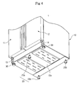
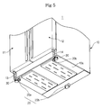
- FIGS. 4 and 5 illustrate alternative structures or positions of the rolling unit 20 of the refrigerator 1 according to alternative embodiments of the present invention. Hereinafter, as the alternative embodiments shown in FIGS. 4 and 5 will be described.
- FIG. 4 is a schematic exploded perspective view illustrating a bottom surface of a refrigerator in accordance with a second embodiment of the present invention.
- the refrigerator 1 of the second embodiment is the same as that of the first embodiment except that the front and rear wheels 20a and 20b of the rolling unit 20 are rolling balls.
- the rolling unit 20 includes one front wheel 20a, having a ball structure, installed at the approximately central point of the front part of the bottom surface 10a of the main body 10, and a pair of rear wheels 20b, each having a ball structure, installed at both corners of the rear part of the bottom surface 10a of the main body 10.
- the refrigerator 1 of the second embodiment can be rapidly moved rectilinearly or curved by a small force, compared to the refrigerator 1 of the first embodiment in which the front and rear wheels 20a and 20b of the rolling unit 20 are respectively made of rollers.
- FIG. 5 is a schematic exploded perspective view illustrating a bottom surface of a refrigerator in accordance with a third embodiment of the present invention.
- the refrigerator 1 of the third embodiment is the same as that of the first embodiment except that positions of the front and rear wheels 20a and 20b of the rolling unit 20 are modified.
- the rolling unit 20 includes a pair of front wheels 20a installed at both corners of the front part of the bottom surface 10a of the main body 10 and serving as one moving member, and one rear wheel 20b installed at the approximately central point of the rear part of the bottom surface 10a and serving as other moving members.
- the refrigerator 1 of the third embodiment is moved while supported at three points on the floor 5 of the indoor space in the same manner as those of the first and second embodiments, thus being easily and rapidly moved.
- the above-described embodiments of the present invention provide a refrigerator, which is moved while supported at three points, thus being easily and rapidly moved compared to conventional refrigerators. Further, the refrigerator is easily and rapidly leveled when the refrigerator is located at a desired position, thus being rapidly handled. Moreover, since freezing and chilling chamber doors of the refrigerator are leveled without tilting in the transverse and longitudinal directions, sealing force of the freezing and chilling chamber doors is improved and opening and closing operation of the freezing and chilling chamber doors is smoothly performed.
- the refrigerator of the above-described embodiments of the present invention is moved and installed while supported at three points, a difference of heights of the doors can be efficiently adjusted.
- gaskets installed on the doors more firmly contact a main body of the refrigerator, thereby preventing cold air from being discharged to the outside of the main body and improving cooling efficiency of the refrigerator.
- the refrigerator of the above-described embodiments of the present invention prevents fan noise, generated therefrom, from being audible due to firm contact between the main body and the doors, and efficiently adjusts a difference of heights of the doors, thereby easily adjusting the gradient of a machinery chamber in the main body, thus easily and efficiently reducing noise generated from compressors and fans installed in the machinery chamber.
Landscapes
- Engineering & Computer Science (AREA)
- Chemical & Material Sciences (AREA)
- Combustion & Propulsion (AREA)
- Physics & Mathematics (AREA)
- Mechanical Engineering (AREA)
- Thermal Sciences (AREA)
- General Engineering & Computer Science (AREA)
- Devices That Are Associated With Refrigeration Equipment (AREA)
- Refrigerator Housings (AREA)
Abstract
A refrigerator (1), which minimizes and easily adjusts a difference of heights of doors, and reduces the number of contact points with a floor of an indoor space, thereby being easily moved and installed. A pair of rear wheels (20b) are installed at both corners of a rear part of a bottom surface (10a) of a main body (10) and one front wheel (20a) is installed at an approximately central point of a front part of the bottom surface (10a) so that the refrigerator (1) is moved while the refrigerator (1) is supported at three points. Height adjustable legs (30), heights of which are adjusted, are installed at both corners of the front part of the bottom surface (10a), and the height adjustable legs (30) together with the front and rear wheels allow the refrigerator (1) to be leveled.
Description
- The present invention relates to refrigerators.
- Generally, a refrigerator serves to store various foods in a fresh state for a long time by supplying cold air, generated from an evaporator, to storage chambers, such as a chilling chamber and a freezing chamber. Recently, refrigerators having a large volume for storing a large quantity of foods have been manufactured and sold.
- Such a refrigerator having a large volume includes a main body, the front surface of which is opened, a chilling chamber and a freezing chamber divided by a partition vertically disposed in the main body and positioned in parallel at left and right sides, and a chilling chamber door and a freezing chamber door installed on the opened front surface of the main body for opening and closing the chilling and freezing chambers such that the chilling and freezing chamber doors are rotated with respect to respective side ends of the main body.
- The refrigerator also includes a plurality of wheels installed on the bottom surface thereof for easily moving the refrigerator, and a plurality of height adjustable legs for horizontally installing the refrigerator when the refrigerator is located at a desired position.
- For example, Korean Patent Laid-open Publication No. 2001-0003377 discloses a refrigerator, as shown in FIG. 1 thereof, including four wheels installed at four corners of the bottom surface thereof, and two height adjustable legs installed at front corners of the bottom surface thereof.
- Since the four wheels are installed at the four corners of the bottom surface of the refrigerator, the above conventional refrigerator cannot be smoothly moved, and increases the probability of damaging a floor of an indoor space, and after movement, it is difficult to level the refrigerator.
- That is, the conventional refrigerator is moved while supported at four points on the floor of the indoor space by the four wheels, thus requiring a large force for movement. Further, the conventional refrigerator requires excessive support points on the floor of the indoor space, thus increasing the probability of damaging the floor of the indoor space during movement.
- Since the refrigerator must be leveled via the two wheels installed at both front corners of the bottom surface thereof when the refrigerator is located at a desired position, it is difficult to level the refrigerator and it takes considerable time to level the refrigerator.
- When the floor of the indoor space is not even, it is more difficult to move and level the refrigerator.
- Since a refrigerator having a large volume has a large weight, it is more difficult to move the refrigerator while supported at four points in the same manner as the above conventional refrigerator. Further, in this case, since it is difficult to precisely level the refrigerator having the large volume, freezing and chilling chamber doors of the refrigerator sag, thereby decreasing sealing force of the freezing and chilling chamber doors and generating noise when the freezing and chilling chamber doors are opened and closed.
- One aim of preferred embodiments of the invention is to provide a refrigerator, in which one moving member is installed at one of front and rear parts of a main body, thereby minimizing a difference of heights of doors, and easily adjusting the difference of heights of the doors when the refrigerator is installed.
- Another aim of preferred embodiments of the invention is to provide a refrigerator, which reduces the number of contact points between a main body thereof and a floor of an indoor space, thereby being easily moved and installed.
- In accordance with an aspect of the present invention, there is provided a refrigerator including: a main body; and a rolling unit at a bottom surface of the main body and on which the main body is movable, the rolling unit including one moving member at one of a front part and a rear part of the bottom surface, and a plurality of moving members at the other of the front and rear parts.
- The one moving member may be installed at the front part of the bottom surface of the main body, the plural moving members may be installed at the rear part of the bottom surface of the main body, and height adjustable legs may be installed at both corners of the front part of the bottom surface of the main body.
- The one moving member may be disposed at an approximately central point of the bottom surface of the main body.
- According to another aspect of the present invention, there is provided a refrigerator including: a main body having a pair of doors respectively hinged at right and left corners of a front of the main body; a rolling unit at a bottom surface of the main body and on which the main body is movable, and including one moving member at one of a front part and a rear part of the bottom surface, and a plurality of moving members at the other of the front and rear parts; and a plurality of height adjustable legs at both corners of the front part of the bottom surface.
- Further features of the present invention are set out in the appended claims.
- The present invention will become apparent and more readily appreciated from the following detailed description, by way of example only, taken in conjunction with the accompanying drawings of which:
- FIG. 1 is a schematic exploded perspective view illustrating a bottom surface of a refrigerator in accordance with a first embodiment of the present invention;
- FIG. 2 is a partial front view of the refrigerator of FIG. 1, in a state in which the position of the refrigerator is moved when the refrigerator is supported at three points;
- FIG. 3 is a partial front view of the refrigerator of FIG. 1, in a state in which the position of the refrigerator is fixed;
- FIG. 4 is a schematic exploded perspective view illustrating a bottom surface of a refrigerator in accordance with a second embodiment of the present invention; and
- FIG. 5 is a schematic exploded perspective view illustrating a bottom surface of a refrigerator in accordance with a third embodiment of the present invention.
- Reference will now be made in detail to embodiments of the present invention, examples of which are illustrated in the accompanying drawings, wherein like reference numerals refer to the like elements throughout. The embodiments are described below in order to explain the present invention by referring to the figures.
- FIG. 1 is a schematic exploded perspective view illustrating a bottom surface of a refrigerator in accordance with a first embodiment of the present invention.
- As shown in FIG. 1, the
refrigerator 1 in accordance with the first embodiment of the present invention includes amain body 10 provided with an opened front surface and including a freezing chamber (not shown) and a chilling chamber (not shown) for containing foods therein, afreezing chamber door 11 and achilling chamber door 12 installed on the opened front surface of themain body 10 for respectively opening and closing the freezing chamber and the chilling chamber, and arolling unit 20 and a plurality of heightadjustable legs 30 installed on abottom surface 10a of themain body 10. - The
freezing chamber door 11 is hinged to one side end of themain body 10 by ahinge member 13 such that thefreezing chamber door 11 can be rotated, and thechilling chamber door 12 is hinged to the other side end of themain body 10 by ahinge member 14 such that thechilling chamber door 12 can be rotated. - The
refrigerator 1 has a side-by-side structure such that thefreezing chamber door 11 and thechilling chamber door 12 are respectively hinged to both side ends, i.e., left and right ends, of themain body 10 and are disposed in parallel, thus having a large storage volume. The above side-by-side refrigerator 1 has a large total weight of themain body 10, and the freezing and chillingchamber doors - When the
refrigerator 1 is installed on a floor 5 (as shown in FIG. 2) of the indoor space and therefrigerator 1 is not positioned in parallel with thefloor 5, the heavy freezing and chillingchamber doors chamber doors - The rolling
unit 20 installed on thebottom surface 10a of themain body 10 serves to allow therefrigerator 1 to be easily and rapidly moved, and a plurality of the heightadjustable legs 30 installed on thebottom surface 10a of themain body 10 together with therolling unit 20 serve to allow therefrigerator 1 to be installed on thefloor 5 of the indoor space in parallel with thefloor 5 together with the operation of therolling unit 20. - The rolling
unit 20 includes onefront wheel 20a installed at an approximately central point of the front part of thebottom surface 10a of themain body 10 and serving as an moving member, and a pair ofrear wheels 20b installed at both corners of the rear part of thebottom surface 10a and serving as other moving members, thereby causing therefrigerator 1 to be moved while supported on thefloor 5 at three points. Thefront wheel 20a and therear wheels 20b are respectively made of rollers, which are rotatably installed on thebottom surface 10. - The
front wheel 20a is installed close to a point on thebottom surface 10a of themain body 10 at which a an unhinged side of thefreezing chamber door 11 faces an unhinged side of thechilling chamber door 12, and supports the unhinged sides of the freezing and chillingchamber doors side refrigerator 1 having a comparatively large weight, thereby leveling the freezing and chillingchamber doors - Further, the height
adjustable legs 30 are installed at both corners of the front part of thebottom surface 10a such that heights of the heightadjustable legs 30 can be adjusted, thereby allowing therefrigerator 1 to be installed at a desired position when therefrigerator 1 is leveled. - Hereinafter, with reference to FIGS. 2 and 3, a process for moving the
refrigerator 1 to a target position and leveling the refrigerator by means of the above-describedrolling unit 20 and heightadjustable legs 30 will be described. - FIG. 2 is a partial front view of the
refrigerator 1 when therefrigerator 1 is moved while supported at three points by the front andrear wheels refrigerator 1 when therefrigerator 1 is installed on thefloor 5 of the indoor space when therefrigerator 1 is leveled on thefloor 5 by the front andrear wheels adjustable legs 30. - As shown in FIG. 2, in order to move the position of the
refrigerator 1, when therefrigerator 1 is pushed when the heightadjustable legs 30 are raised so that the front andrear wheels floor 5 of the indoor space, the front andrear wheels refrigerator 1, which is supported at three points on thefloor 5 of the indoor space, is moved. - As described above, the
refrigerator 1 is moved while supported at three points on thefloor 5 of the indoor space, thus being capable of being smoothly and rapidly moved even when thefloor 5 of the indoor space is not even, compared to the conventional refrigerator, which is moved while supported at four points, and decreasing the probability of damaging thefloor 5 of the indoor space due to the careless movement. - After the
refrigerator 1 is moved to a desired position, the front part of themain body 10 is supported at one point by thefront wheel 20a installed at the approximately central point of thebottom surface 10a of themain body 10. Accordingly, as long as the rear part of themain body 10 supported by therear wheels 20b is horizontally disposed, the front part of themain body 10 can be horizontally disposed. - Further, in the case that the
refrigerator 1 is not leveled, it can be easily determined whether or not therefrigerator 1 is tilted to one side by means of thefront wheel 20a installed at the approximately central point of thebottom surface 10a of the main body. - Accordingly, as shown in FIG. 3, when the height
adjustable legs 30 installed at both corners of the front part of thebottom surface 10 are lowered so that the heights of the heightadjustable legs 30 are adjusted, therefrigerator 1, which was leveled, is supported by the front andrear wheels adjustable legs 30. - FIGS. 4 and 5 illustrate alternative structures or positions of the
rolling unit 20 of therefrigerator 1 according to alternative embodiments of the present invention. Hereinafter, as the alternative embodiments shown in FIGS. 4 and 5 will be described. - FIG. 4 is a schematic exploded perspective view illustrating a bottom surface of a refrigerator in accordance with a second embodiment of the present invention. As shown in FIG. 4, the
refrigerator 1 of the second embodiment is the same as that of the first embodiment except that the front andrear wheels rolling unit 20 are rolling balls. - That is, in the
refrigerator 1 of the second embodiment, therolling unit 20 includes onefront wheel 20a, having a ball structure, installed at the approximately central point of the front part of thebottom surface 10a of themain body 10, and a pair ofrear wheels 20b, each having a ball structure, installed at both corners of the rear part of thebottom surface 10a of themain body 10. - Accordingly, the
refrigerator 1 of the second embodiment can be rapidly moved rectilinearly or curved by a small force, compared to therefrigerator 1 of the first embodiment in which the front andrear wheels rolling unit 20 are respectively made of rollers. - FIG. 5 is a schematic exploded perspective view illustrating a bottom surface of a refrigerator in accordance with a third embodiment of the present invention. As shown in FIG. 5, the
refrigerator 1 of the third embodiment is the same as that of the first embodiment except that positions of the front andrear wheels rolling unit 20 are modified. - That is, in the
refrigerator 1 of the third embodiment, therolling unit 20 includes a pair offront wheels 20a installed at both corners of the front part of thebottom surface 10a of themain body 10 and serving as one moving member, and onerear wheel 20b installed at the approximately central point of the rear part of thebottom surface 10a and serving as other moving members. - Accordingly, the
refrigerator 1 of the third embodiment is moved while supported at three points on thefloor 5 of the indoor space in the same manner as those of the first and second embodiments, thus being easily and rapidly moved. - The above-described embodiments of the present invention provide a refrigerator, which is moved while supported at three points, thus being easily and rapidly moved compared to conventional refrigerators. Further, the refrigerator is easily and rapidly leveled when the refrigerator is located at a desired position, thus being rapidly handled. Moreover, since freezing and chilling chamber doors of the refrigerator are leveled without tilting in the transverse and longitudinal directions, sealing force of the freezing and chilling chamber doors is improved and opening and closing operation of the freezing and chilling chamber doors is smoothly performed.
- Since the refrigerator of the above-described embodiments of the present invention is moved and installed while supported at three points, a difference of heights of the doors can be efficiently adjusted. Thereby, gaskets installed on the doors more firmly contact a main body of the refrigerator, thereby preventing cold air from being discharged to the outside of the main body and improving cooling efficiency of the refrigerator.
- The refrigerator of the above-described embodiments of the present invention prevents fan noise, generated therefrom, from being audible due to firm contact between the main body and the doors, and efficiently adjusts a difference of heights of the doors, thereby easily adjusting the gradient of a machinery chamber in the main body, thus easily and efficiently reducing noise generated from compressors and fans installed in the machinery chamber.
- Although a few embodiments of the present invention have been shown and described, the present invention is not limited to the described embodiments. Instead, it would be appreciated by those skilled in the art that changes may be made to these embodiments without departing from the principles and spirit of the invention, the scope of which is defined by the claims and their equivalents.
- Attention is directed to all papers and documents which are filed concurrently with or previous to this specification in connection with this application and which are open to public inspection with this specification, and the contents of all such papers and documents are incorporated herein by reference.
- All of the features disclosed in this specification (including any accompanying claims, abstract and drawings), and/or all of the steps of any method or process so disclosed, may be combined in any combination, except combinations where at least some of such features and/or steps are mutually exclusive.
- Each feature disclosed in this specification (including any accompanying claims, abstract and drawings) may be replaced by alternative features serving the same, equivalent or similar purpose, unless expressly stated otherwise. Thus, unless expressly stated otherwise, each feature disclosed is one example only of a generic series of equivalent or similar features.
- The invention is not restricted to the details of the foregoing embodiment(s). The invention extends to any novel one, or any novel combination, of the features disclosed in this specification (including any accompanying claims, abstract and drawings), or to any novel one, or any novel combination, of the steps of any method or process so disclosed.
Claims (10)
- A refrigerator (1) comprising:a main body (10); anda rolling unit (20) at a bottom surface (10a) of the main body (10) and on which the main body (10) is movable, the rolling unit (20) including one moving member (20a) at one of a front part and a rear part of the bottom surface (10a), and a plurality of moving members (20b) at the other of the front and rear parts.
- The refrigerator (1) as set forth in claim 1, wherein the one moving member (20a) is at the front part of the bottom surface (10a), the plural moving members (20b) are installed at left and right sides of the rear part of the bottom surface (10a), and height adjustable legs (30) are installed at both corners of the front part of the bottom surface (10a).
- The refrigerator (1) as set forth in claim 1, further comprising height adjustable legs (30) at left and right sides of the one moving member (20a).
- The refrigerator (1) as set forth in any preceding claim, wherein the one moving member (20a) is at an approximately central point of the bottom surface (10a).
- The refrigerator (1) as set forth in any preceding claim, wherein the number of the plural moving members (20b) is two, and the two moving members (20b) are respectively disposed at both corners of the rear part of the bottom surface (10a).
- A refrigerator (1) comprising:a main body (10) having a pair of doors (11, 12) respectively hinged at right and left corners of a front of the main body (10);a rolling unit (20) at a bottom surface (10a) of the main body (10) and on which the main body (10) is movable, and including one moving member (20a) at one of a front part and a rear part of the bottom surface (10a), and a plurality of moving members (20b) at the other of the front and rear parts; anda plurality of height adjustable legs (30) at both corners of the front part of the bottom surface (10a).
- The refrigerator (1) as set forth in claim 6, wherein the one moving member (20a) is at the front part of the bottom surface (10a), the plural moving members (20b) are at left and right sides of the rear part of the bottom surface (10a).
- The refrigerator (1) as set forth in claim 6 or claim 7, further comprising height adjustable legs (30) at left and right sides of the one moving member (20a).
- The refrigerator (1) as set forth in claim 6, wherein the one moving member (20a) is at an approximately central point of the bottom surface.
- The refrigerator (1) as set forth in any one of claims 6-9, wherein the number of the plural moving members (20b) is two, and the two moving members (20b) are respectively disposed at both corners of the rear part of the bottom surface (10a).
Applications Claiming Priority (1)
| Application Number | Priority Date | Filing Date | Title |
|---|---|---|---|
| KR1020040068206A KR100611317B1 (en) | 2004-08-28 | 2004-08-28 | Refrigerator |
Publications (1)
| Publication Number | Publication Date |
|---|---|
| EP1630501A1 true EP1630501A1 (en) | 2006-03-01 |
Family
ID=36093173
Family Applications (1)
| Application Number | Title | Priority Date | Filing Date |
|---|---|---|---|
| EP05253296A Withdrawn EP1630501A1 (en) | 2004-08-28 | 2005-05-27 | Refrigerator |
Country Status (4)
| Country | Link |
|---|---|
| US (1) | US20060042306A1 (en) |
| EP (1) | EP1630501A1 (en) |
| KR (1) | KR100611317B1 (en) |
| CN (1) | CN100520250C (en) |
Families Citing this family (22)
| Publication number | Priority date | Publication date | Assignee | Title |
|---|---|---|---|---|
| KR100850962B1 (en) * | 2007-04-24 | 2008-08-08 | 엘지전자 주식회사 | Damping adjuster and refrigerator with same |
| KR100850961B1 (en) * | 2007-04-24 | 2008-08-08 | 엘지전자 주식회사 | Refrigerator |
| KR100850963B1 (en) * | 2007-05-25 | 2008-08-08 | 엘지전자 주식회사 | Refrigerator |
| US8205843B2 (en) * | 2009-09-02 | 2012-06-26 | Electrolux Home Products, Inc. | Rollerball leveling leg |
| CN102980342A (en) * | 2012-12-28 | 2013-03-20 | 合肥美的荣事达电冰箱有限公司 | Refrigerator |
| JP2014222126A (en) * | 2013-05-14 | 2014-11-27 | 株式会社東芝 | Refrigerator |
| CN104677030A (en) * | 2015-03-13 | 2015-06-03 | 湖北美的电冰箱有限公司 | Foot assembly for refrigerator and refrigerator with foot assembly |
| US10663175B2 (en) * | 2017-05-30 | 2020-05-26 | Samsung Electronics Co., Ltd. | Home appliance |
| CN107388677A (en) * | 2017-07-28 | 2017-11-24 | 合肥华凌股份有限公司 | Refrigerator, refrigerator roller structure and its application method |
| KR20210007648A (en) * | 2019-07-12 | 2021-01-20 | 엘지전자 주식회사 | refrigerator |
| KR102892694B1 (en) | 2019-07-12 | 2025-11-27 | 엘지전자 주식회사 | Refrigerator |
| KR102836705B1 (en) | 2019-07-12 | 2025-07-18 | 엘지전자 주식회사 | refrigerator |
| KR102880310B1 (en) | 2019-07-12 | 2025-11-03 | 엘지전자 주식회사 | Refrigerator having drawer type door |
| KR20210007642A (en) | 2019-07-12 | 2021-01-20 | 엘지전자 주식회사 | Refrigerator having drawer type door |
| CN112212574B (en) | 2019-07-12 | 2022-06-24 | Lg电子株式会社 | Refrigerator with a door |
| KR102892222B1 (en) | 2019-07-12 | 2025-11-27 | 엘지전자 주식회사 | refrigerator |
| KR20210007644A (en) | 2019-07-12 | 2021-01-20 | 엘지전자 주식회사 | refrigerator |
| KR20210008709A (en) | 2019-07-15 | 2021-01-25 | 엘지전자 주식회사 | Refrigerator and control method thereof |
| KR102805224B1 (en) | 2019-07-15 | 2025-05-12 | 엘지전자 주식회사 | Refrigerator and control method thereof |
| EP4048968B1 (en) * | 2019-10-25 | 2024-07-10 | Electrolux Do Brasil S.A. | Household appliance |
| EP4130622A4 (en) * | 2020-04-17 | 2023-08-23 | Samsung Electronics Co., Ltd. | REFRIGERATOR |
| KR102457281B1 (en) * | 2021-01-15 | 2022-10-20 | 엘지전자 주식회사 | Refrigerator |
Citations (3)
| Publication number | Priority date | Publication date | Assignee | Title |
|---|---|---|---|---|
| JP2001194049A (en) * | 2000-01-13 | 2001-07-17 | Sawafuji Electric Co Ltd | Adjuster bolt for cold storage |
| JP2002081840A (en) * | 2000-09-04 | 2002-03-22 | Toshiba Corp | refrigerator |
| JP2003161572A (en) * | 2001-11-29 | 2003-06-06 | Hitachi Ltd | refrigerator |
Family Cites Families (14)
| Publication number | Priority date | Publication date | Assignee | Title |
|---|---|---|---|---|
| US2803510A (en) * | 1954-04-02 | 1957-08-20 | Gen Electric | Cabinet, including retractable caster device |
| US2874971A (en) * | 1955-12-23 | 1959-02-24 | Philco Corp | Appliance cabinet structure |
| US3482894A (en) * | 1967-12-19 | 1969-12-09 | Umc Ind | Cabinet with casters and leveling means |
| US3534430A (en) * | 1969-04-03 | 1970-10-20 | Gen Motors Corp | Height adjustable caster mechanism |
| JPH01211095A (en) * | 1988-02-15 | 1989-08-24 | Internatl Business Mach Corp <Ibm> | Stopper for cabinet |
| US4955569A (en) * | 1989-07-18 | 1990-09-11 | Sub-Zero Freezer Company, Inc. | Refrigerator leveling system |
| US4932729A (en) * | 1989-11-13 | 1990-06-12 | White Consolidated Industries, Inc. | Door hinge and cabinet support mounting bracket |
| US5215367A (en) * | 1992-05-22 | 1993-06-01 | Amana Refrigeration, Inc. | Refrigerator door hinge |
| US5785293A (en) * | 1995-12-21 | 1998-07-28 | Delta International Machinery Corp. | Machinery base |
| AU741052B2 (en) * | 1997-04-23 | 2001-11-22 | Fisher & Paykel Appliances Limited | Height adjustment or levelling apparatus |
| KR100236481B1 (en) | 1997-05-07 | 2000-01-15 | 양승래 | Round fridge with tumble rack |
| KR19990020182U (en) * | 1997-11-24 | 1999-06-15 | 전주범 | Rotary refrigerator |
| KR200164321Y1 (en) | 1999-07-13 | 2000-02-15 | 삼성전자주식회사 | Supporting device of refrigerator |
| JP2004037008A (en) | 2002-07-04 | 2004-02-05 | Nippon Light Metal Co Ltd | Storage cabinet for cold storage |
-
2004
- 2004-08-28 KR KR1020040068206A patent/KR100611317B1/en not_active Expired - Fee Related
-
2005
- 2005-05-27 EP EP05253296A patent/EP1630501A1/en not_active Withdrawn
- 2005-06-01 CN CNB2005100734913A patent/CN100520250C/en not_active Expired - Fee Related
- 2005-06-02 US US11/142,465 patent/US20060042306A1/en not_active Abandoned
Patent Citations (3)
| Publication number | Priority date | Publication date | Assignee | Title |
|---|---|---|---|---|
| JP2001194049A (en) * | 2000-01-13 | 2001-07-17 | Sawafuji Electric Co Ltd | Adjuster bolt for cold storage |
| JP2002081840A (en) * | 2000-09-04 | 2002-03-22 | Toshiba Corp | refrigerator |
| JP2003161572A (en) * | 2001-11-29 | 2003-06-06 | Hitachi Ltd | refrigerator |
Non-Patent Citations (3)
| Title |
|---|
| PATENT ABSTRACTS OF JAPAN vol. 2000, no. 24 11 May 2001 (2001-05-11) * |
| PATENT ABSTRACTS OF JAPAN vol. 2002, no. 07 3 July 2002 (2002-07-03) * |
| PATENT ABSTRACTS OF JAPAN vol. 2003, no. 10 8 October 2003 (2003-10-08) * |
Also Published As
| Publication number | Publication date |
|---|---|
| KR100611317B1 (en) | 2006-08-10 |
| KR20060019641A (en) | 2006-03-06 |
| US20060042306A1 (en) | 2006-03-02 |
| CN1740711A (en) | 2006-03-01 |
| CN100520250C (en) | 2009-07-29 |
Similar Documents
| Publication | Publication Date | Title |
|---|---|---|
| EP1630501A1 (en) | Refrigerator | |
| US9464841B2 (en) | Refrigerator | |
| US8740322B2 (en) | Refrigerator with slidable shelf | |
| US12163722B2 (en) | Refrigerator | |
| US9791207B2 (en) | Refrigerator | |
| EP2594875B1 (en) | Refrigerator | |
| US20180259246A1 (en) | Lifting apparatus and refrigerator having the same | |
| US20150260445A1 (en) | Refrigerator | |
| EP1462743A1 (en) | Recessed refrigerator | |
| KR101899808B1 (en) | Refrigerator | |
| BR112013027716B1 (en) | quick drawer and refrigerator | |
| KR101622231B1 (en) | Refrigerator | |
| US20180087828A1 (en) | Refrigerator | |
| JP2983447B2 (en) | Refrigerator drawer structure | |
| AU2005200497B2 (en) | Refrigerating storage | |
| JP2003322465A (en) | refrigerator | |
| JP3371077B2 (en) | refrigerator | |
| US11519659B2 (en) | Refrigerator | |
| US20210231364A1 (en) | Refrigerator | |
| JP5809547B2 (en) | Cooling storage | |
| JP2002022353A (en) | refrigerator | |
| KR200164321Y1 (en) | Supporting device of refrigerator | |
| JP2005009698A (en) | Temperature control storage and refrigerator | |
| JP2003176972A (en) | Storage house | |
| KR0133333Y1 (en) | A refrigerator |
Legal Events
| Date | Code | Title | Description |
|---|---|---|---|
| PUAI | Public reference made under article 153(3) epc to a published international application that has entered the european phase |
Free format text: ORIGINAL CODE: 0009012 |
|
| AK | Designated contracting states |
Kind code of ref document: A1 Designated state(s): AT BE BG CH CY CZ DE DK EE ES FI FR GB GR HU IE IS IT LI LT LU MC NL PL PT RO SE SI SK TR |
|
| AX | Request for extension of the european patent |
Extension state: AL BA HR LV MK YU |
|
| AKX | Designation fees paid |
Designated state(s): DE FR GB |
|
| 17P | Request for examination filed |
Effective date: 20060502 |
|
| STAA | Information on the status of an ep patent application or granted ep patent |
Free format text: STATUS: THE APPLICATION IS DEEMED TO BE WITHDRAWN |
|
| 18D | Application deemed to be withdrawn |
Effective date: 20100217 |