EP1630372A1 - Shell main body for muffler - Google Patents
Shell main body for muffler Download PDFInfo
- Publication number
- EP1630372A1 EP1630372A1 EP05291634A EP05291634A EP1630372A1 EP 1630372 A1 EP1630372 A1 EP 1630372A1 EP 05291634 A EP05291634 A EP 05291634A EP 05291634 A EP05291634 A EP 05291634A EP 1630372 A1 EP1630372 A1 EP 1630372A1
- Authority
- EP
- European Patent Office
- Prior art keywords
- shell
- main body
- end portion
- arc portions
- shell main
- Prior art date
- Legal status (The legal status is an assumption and is not a legal conclusion. Google has not performed a legal analysis and makes no representation as to the accuracy of the status listed.)
- Granted
Links
Images



Classifications
-
- F—MECHANICAL ENGINEERING; LIGHTING; HEATING; WEAPONS; BLASTING
- F01—MACHINES OR ENGINES IN GENERAL; ENGINE PLANTS IN GENERAL; STEAM ENGINES
- F01N—GAS-FLOW SILENCERS OR EXHAUST APPARATUS FOR MACHINES OR ENGINES IN GENERAL; GAS-FLOW SILENCERS OR EXHAUST APPARATUS FOR INTERNAL-COMBUSTION ENGINES
- F01N13/00—Exhaust or silencing apparatus characterised by constructional features
- F01N13/18—Construction facilitating manufacture, assembly, or disassembly
- F01N13/1872—Construction facilitating manufacture, assembly, or disassembly the assembly using stamp-formed parts or otherwise deformed sheet-metal
-
- F—MECHANICAL ENGINEERING; LIGHTING; HEATING; WEAPONS; BLASTING
- F01—MACHINES OR ENGINES IN GENERAL; ENGINE PLANTS IN GENERAL; STEAM ENGINES
- F01N—GAS-FLOW SILENCERS OR EXHAUST APPARATUS FOR MACHINES OR ENGINES IN GENERAL; GAS-FLOW SILENCERS OR EXHAUST APPARATUS FOR INTERNAL-COMBUSTION ENGINES
- F01N13/00—Exhaust or silencing apparatus characterised by constructional features
- F01N13/08—Other arrangements or adaptations of exhaust conduits
-
- F—MECHANICAL ENGINEERING; LIGHTING; HEATING; WEAPONS; BLASTING
- F01—MACHINES OR ENGINES IN GENERAL; ENGINE PLANTS IN GENERAL; STEAM ENGINES
- F01N—GAS-FLOW SILENCERS OR EXHAUST APPARATUS FOR MACHINES OR ENGINES IN GENERAL; GAS-FLOW SILENCERS OR EXHAUST APPARATUS FOR INTERNAL-COMBUSTION ENGINES
- F01N2470/00—Structure or shape of exhaust gas passages, pipes or tubes
- F01N2470/10—Tubes having non-circular cross section
-
- F—MECHANICAL ENGINEERING; LIGHTING; HEATING; WEAPONS; BLASTING
- F01—MACHINES OR ENGINES IN GENERAL; ENGINE PLANTS IN GENERAL; STEAM ENGINES
- F01N—GAS-FLOW SILENCERS OR EXHAUST APPARATUS FOR MACHINES OR ENGINES IN GENERAL; GAS-FLOW SILENCERS OR EXHAUST APPARATUS FOR INTERNAL-COMBUSTION ENGINES
- F01N2470/00—Structure or shape of exhaust gas passages, pipes or tubes
- F01N2470/24—Concentric tubes or tubes being concentric to housing, e.g. telescopically assembled
Definitions
- the present invention relates to a shell main body for a muffler that is used in an exhaust system of a combustion engine mounted on a motor vehicle or the like and is equipped with an inner shell and an outer shell wrapping an outer surface of the inner shell.
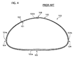
- a shell main body for a muffler with an inner shell and an outer shell As a shell main body for a muffler with an inner shell and an outer shell, a shell main body disclosed in Japanese Patent Application Laid-open No. 2002-206422 is conventionally known. As shown in a schematic cross-sectional view in FIG. 4, a shell main body 103 of this conventional muffler is formed of two layers of an inner shell 101 and an outer shell 102. Each of the inner and outer shells 101 and 102 has a cylindrical shape with a cross section that is not a perfect circle but is defined by small arc portions 104 and 104 alternating with large arc portions 105 and 105, similarly to an oval, a racing track-like figure, or the like.
- the conventional shell main body 103 for the muffler described above has the following problem.
- the shell main body 103 is provided at its edge portions with openings, which are closed by not-shown end plates by press caulking or welding, respectively.
- This structure makes it impossible for the end plates and the inner shell 101 to be welded to each other, thus causing not-shown minute gaps which are located between an inner surface of the end plates and the edge portions of the inner shell 101 and communicate an inner space of the shell main body 103 and gaps 104a, 104b, 105a, and 105b formed between the inner shell 101 and the outer shell 102, because the inner shell 101 are covered by the end plates and the outer shell 102.
- the edge portions of the inner shell 101 and the outer shell 102 have overlap portions 108 that are welded with each other in a state that they are overlapped with each other at a top position and in a circumstantial direction of the shell main body 103.
- the water that has entered the gaps 104a, 104b, 105a, and 105b is heated by high-temperature exhaust gas passing through the muffle to vaporize after restarting the engine, resulting in pressure rise of the vapor in the gaps 104a, 104b, 105a, and 105b.
- this pressure rise speed exceeds a discharging speed of the vapor that is discharged from the gaps 104a, 104b, 105a, and 105b to the inner portion or an outside of the shell main body 103, vapor pressure in the gaps 104a, 104b, 105a, and 105b between the shells 101 and 102 sometimes rises to deform them.
- a communicating path for example a hole, is formed on a shell overlap portion at an upper surface side of the shell main body 103 so as to allow the gap between the inner shell 101 and the outer shell 102 to communicate with the outside of the outer shell 102 or gaps at the edge portion of the outer shell 102 is formed so that the vapor entered into the gap can pass through the gaps of the outer shell 102.
- a shell main body 103 having a cylindrical shape with a cross section that is not a perfect circle but is defined by small arc portions 104 and 104 alternating with large arc portions 105 and 105, similarly to an oval, a racing track, or the like the inner shell 101 and the outer shell 102 in the right and left small arc portions 104 and 104 are in close contact with each other, clogging their right and left side gaps 104a and 104b and dividing the gap into an upper gap 105b and a lower gap 105a in the large arc portions 105 and 105 as shown in FIG. 5.
- This clogging prevents the vapor generated in the lower gap 105a between the lower portions of the inner shell 101 and the outer shell 103 from discharging from the lower gap 105a, resulting in pressure-rise of the vapor to apply its pressure force P to and deform the lower portions of the shells 101 and 102 in an expansion direction.
- the lower large arc portion 105 of the shells 101 and 102 is deformable easily more than the small arc portions 104 and 104, because the former has stiffness smaller than the former.
- a shell main body for a muffler comprises: an inner shell having an end portion and formed in a cylindrical shape with a cross section that is noncircular and defined by small arc portions alternating with large arc portions; an outer shell wrapping an outer surface of the inner shell and formed in a cylindrical shape with a cross section that is noncircular and defined by small arc portions alternating with large arc portions, the outer shell having an end portion; and end plates secured to both edge portions of the outer shell wherein the end portion of the inner shell and the end portion of the outer shell are overlapped in a circumstantial direction of the shell main body to form a shell overlap portion that is capable of forming a clearance between the inner shell and the outer shell for discharging vapor in a gap of the large arc portions formed between the inner shell and the outer shell into one of an outside and an inside of the shell main body, with the shell overlapping portion being located in one of the small arc portions.
- the inner shell and the outer shell are formed of a double-rolled flat plate. This brings reduction of manufacturing cost with ensuring decrease of transmission noise and leak prevention of exhaust gas
- the large arc portions are separated from each other in a vertical direction to be located in an upper position and a lower position of the shell main body, and the small arc portions are separated from each other in a horizontal direction to be located in side positions of the shell main body with connecting the large arc portions. Therefore, this structure enables the shell main body 3 to be short in height so as to avoid interference of the shell main body and a road surface with obtaining a necessary passage area for passing exhaust gas through an inside of it.
- the end portion of the outer shell is headed downward. Therefore, when rainwater and/or antifreezing agent that comes from the outside of the shell main body and adhere to an outer surface of the outer shell is transmitted through the outer surface and falls, but does not easily enter the gap through the clearance of the shell overlap portion.
- the end portion of the inner shell is headed upward and located at a position higher than a bottom portion of an inner surface of the inner shell. Therefore, water accumulated in the bottom portion of the shell main body does not easily enter the gap through the clearance of the shell overlap portion.
- the shell overlap portion is constructed by the end portion of the inner shell and the end portion of the outer shell that are spot-welded in positions at intervals in a longitudinal direction of the shell main body so that the clearance between the spot-welded positions allows the vapor to be discharged.
- This enables this gap for discharging the vapor to be easily formed at a low manufacturing cost, because its welding length is shorten to form the gap for vapor discharging.
- the shell overlap portion includes the end portion of the inner shell, the end portion of the outer shell, and a sandwiched portion that is sandwiched between the end portions with the sandwiching portion integrally connecting the inner shell and the outer shell and dividing the clearance into a first clearance for communicating the gap and the inside of the shell main body and a second clearance for communicating the gap and the outside of the shell main body. Therefore, this structure enables the overlap portion to be easily made of one flat plate and formed with the clearances for vapor discharging into the outside and the inside of the shell main body.
- the clearance has a small area to prevent water from entering the gap therethrough when pressure is low in the gap, and it has a large area to discharge vapor in the gap therethrough into the inside or outside of the shell main body.
- FIGS. 1 and 3 First, a shell main body for a muffler of an embodiment will be described with reference to the accompanying drawings of FIGS. 1 and 3.
- FIG. 1 is a plane view showing the shell main body of the embodiment
- FIG. 2 is a cross-sectional view showing the shell main body taken along the II-II line in FIG. 1
- FIG. 3 is a schematic diagram illustrating a state of vapor discharging in the shell main body shown in FIGS. 1 and 2.
- the shell main body 3 of the embodiment is used for a muffler of an exhaust system mounted on a motor vehicle.
- the muffler is connected at its both ends with not-shown exhaust pipes.
- the shell main body 3 is made of a double-rolled flat plate, formed of two layers of an inner shell 1 and an outer shell 2 so that it has a laterally long, flattish cylindrical shape with a cross section substantially in a laterally long, rounded triangle shape.
- the shell main body 3 has small arc portions 4 and 5 alternating with large arc portions 6 and 7, the small arc portions 4 and 5 having a small curvature in a state that the inner shell 1 and the outer shell 2 are attached almost firmly to each other to form a left clearance, which will be described later, and a right gap 5a, and the large arc portions 6 and 7 having a large curvature in a state that a lower gap 6a and an upper gap 7a are formed between the inner shell 1 and the outer shell 2.
- the small arc portions 4 and 5 are separated from each other in a horizontal direction to be located in side positions of the shell main body 3 with connecting the large arc portions 6 and 7, and the large arc portions 6 and 7 are separated from each other in a vertical direction to be located in an upper position and a lower position of the shell main body 3.
- the small arc portions 4 and 5 and the large arc portions 6 and 7 form an inner space I inside of them so as to pass exhaust gas.
- an end portion 1a of the inner shell 1 and an end portion 2a of the outer shell 4 are overlapped in a circumstantial direction of the shell main body 3 to each form a shell overlap portion 8 being spot-welded in positions S that are a predetermined interval apart from one another in a longitudinal direction of the shell main body 3.
- the shell overlap portion 8 further includes a sandwiched portion 12a of the plate that is sandwiched between the end portions 1a and 2a, thus having three-layer shell portions.
- an overlap amount of the shell overlap portion 8 (an overlap amount of the end portion 1a of the inner shell 1 and the end portion 2a of the outer shell 2) is 20 mm, and a center portion of the shell overlap portion 8 is spot-welded in the positions S such that three-layer shell portions are fixed to one another at the shell overlap portion 8.
- Non-welded portions between the spot-welded positions S form the clearance for discharging water vapor in the gaps 5a, 6a, and 7a.
- the end portion 1a of the inner shell 1 is positioned in the small arc portion 4 to be erected upward from a bottom portion of an inner space I of the shell main body 3 to be located at a position higher than the bottom portion and secured to an inner peripheral surface of the sandwiched portion 12a at spot-welded positions S, while an end portion 2a of the outer shell 2 is headed downward in the small arc portion 4 and secured to an outer peripheral surface of the sandwiched portion 12a at the spot-welded positions S.
- the shell overlap portion 8 is formed to have the clearance, which includes a first clearance 1b formed between the end portion 1a of the inner shell 1 and an inner peripheral surface of the sandwiched portion 12a and a second clearance 2b formed between the end portion 2a of the outer shell 2 and an outer peripheral surface of the sandwiched portion 12a.
- the end portions 1b and 2b are deformable to spread their discharging areas and discharge the vapor in the gaps 5a, 6a , and 7a when pressure of vapor in the gaps 6a and 7a becomes high.
- not-shown interior parts such as baffle plates, communicating pipes, and others, are contained. Openings of both edge portions of the shell main body 3 are closed by end plates 9 and 10, respectively, by press-caulking or welding the end plates 9 and 10 and the edge portions of the outer shell 2.
- the end plate 9 is fixed to a not-shown inlet exhaust pipe
- the end plate 10 is fixed to a not-shown outlet exhaust pipe, so that the inner space I is communicated with the inlet exhaust pipe and the outlet exhaust pipe to flow exhaust gas outputted from an engine to the outside with decreasing transmission noise of the gas.
- the shell main body 3 is made of a double-rolled flat plate so that it is formed of two layers of the inner shell 1 and the outer shell 2, which brings decrease of transmission noise and leak prevention of exhaust gas.
- water such as flocculated water generated from water vapor contained in exhaust gas by cooling-off
- the muffler is thereafter heated by the exhaust gas discharged from the engine in operation after restarting the engine, so that the water vaporizes to increase its volume, resulting in increase of pressure in the gaps 5a, 6a, and 7a formed between the inner shell 1 and the outer shell 2.
- the shell main body 3 is constructed such that the small arc portions 4 and 5 of the inner shell 1 and the outer shell 2 are in contact with each other with the small arc portion 4 being provided with the shell overlap portion 8, which enables the water vapor in the gaps 6a and 7a of the large arc portions 6 and 7 to apply its expansion force and deform the end portions 1a and 2a for spreading discharging areas of the first and second clearances 1b and 2b of the shell overlap portion 8.
- the end portions 1a and 2a are weaker in stiffness than the other portions of the shell main body 3 to be easily deformed by the expansion force of the vapor in the large arc portions 6a and 7a, and the left arc portion 4 so that the clearances 1b and 2b of the end portions 1a and 2a located between the welded positions S are enlarged to pass the vapor in the large arc portions 6a and 7a through the clearances 1b and 2b, because the end portions 1a and 2a are easily deformable due to their low stiffness.
- the vapor accumulated in the lower gap 6a of the lower large arc portion 6 is discharged, as indicated by an arrow W1 in FIG. 3, to the inner space I of the shell main body 3 through the first clearance 1b of the shell overlap portion 8 formed between the end portion 1a of the inner shell 1 and the sandwiched portion 12a, with spreading the clearance 1b by the vapor pressure. Accordingly, the clearance 1b enables pressure rise due to the water accumulated in the lower gap 6a of the lower large arc portion 6 to be suppressed, and thereby preventing the lower large arc portion 6 from being deformed.
- the vapor accumulated in the upper gap 7a of the upper large arc portion 7 is discharged, as indicated by an arrow W2 in FIG. 3, to the outside O of the shell main body 3 through the second clearance 2b of the shell overlap portion 8 formed between the end portion 2a of the outer shell 2 and the sandwiched portion 12a, with spreading the clearance 2b by the vapor pressure. Accordingly, the clearance 2b enables pressure rise due to the water accumulated in the upper gap 7a of the upper large arc portion 7 to be suppressed, and thereby preventing the upper large arc portion 7 from being deformed.
- rainwater and/or antifreezing agent that comes from the outside and adhere to an outer surface of the outer shell 2 is transmitted through the outer surface and falls, but does not easily enter the second clearance 2b formed between the end portion 2a and the sandwiched portion 12a, since the outer shell 2 is rolled around an outer surface of the inner shell 1 so that its end portion 2a is headed downward.
- the shell main body 3 of the embodiment has the following advantages.
- the shell main body 3 is made of one double-rolling flat plate and formed to have the inner shell 1 and outer shell wrapping the inner shell 1 each having noncircular cylindrical shape and defined by the small arc portions 4 and 5 alternating with the large arc portions 6 and 7, and one of the small arc portions 4 and 5 is provided with the shell overlap portion 8 with the clearance for discharging vapor in the gaps 5a, 6a, and 7a into the inside or outside of the shell main body 3. This brings decrease of vapor-pressure rise and prevents the inner shell 1 and the outer shell 2 from being deformed by the vapor pressure rise.
- the water accumulated in the bottom portion of the shell main body 3 does not easily enter the gap 7a through the first clearance 1b of the shell overlap portion 8, since the end portion 1a of the inner shell 1 is headed upward and located at the position higher than a bottom portion of the inner surface of the inner shell 1.
- the shell main body 1 may have a cross section in any other shape, as long as it is not a perfect circle but is defined by alternated small arc portions and large arc portions, for example, a cross section in a laterally long, flattish shape such as an oval and a racing track, or a cross section in a substantially rectangular shape with small arc-shaped corner portions.
- the inner shell 1 and the outer shell 2 are made of one flat plate, but they may be formed of two flat plates or more.
Landscapes
- Engineering & Computer Science (AREA)
- Chemical & Material Sciences (AREA)
- Combustion & Propulsion (AREA)
- Mechanical Engineering (AREA)
- General Engineering & Computer Science (AREA)
- Exhaust Silencers (AREA)
Abstract
Description
- The present invention relates to a shell main body for a muffler that is used in an exhaust system of a combustion engine mounted on a motor vehicle or the like and is equipped with an inner shell and an outer shell wrapping an outer surface of the inner shell.
- As a shell main body for a muffler with an inner shell and an outer shell, a shell main body disclosed in Japanese Patent Application Laid-open No. 2002-206422 is conventionally known. As shown in a schematic cross-sectional view in FIG. 4, a shell
main body 103 of this conventional muffler is formed of two layers of aninner shell 101 and anouter shell 102. Each of the inner andouter shells small arc portions large arc portions - The conventional shell
main body 103 for the muffler described above, however, has the following problem. The shellmain body 103 is provided at its edge portions with openings, which are closed by not-shown end plates by press caulking or welding, respectively. This structure makes it impossible for the end plates and theinner shell 101 to be welded to each other, thus causing not-shown minute gaps which are located between an inner surface of the end plates and the edge portions of theinner shell 101 and communicate an inner space of the shellmain body 103 andgaps inner shell 101 and theouter shell 102, because theinner shell 101 are covered by the end plates and theouter shell 102. - Incidentally, the edge portions of the
inner shell 101 and theouter shell 102 have overlapportions 108 that are welded with each other in a state that they are overlapped with each other at a top position and in a circumstantial direction of the shellmain body 103. - Consequently, water enters the
gaps inner shell 101 and theouter shell 102 due to capillary phenomenon through the gaps between the end plates and theinner shell 101 and accumulates on an inner portion of the muffler when water vapor in exhaust gas is cooled off into the water due to contact with a low-temperature shell wall of the muffler or drop in temperature after stopping an engine. - Then, the water that has entered the
gaps gaps gaps main body 103, vapor pressure in thegaps shells - Incidentally, water causing such a problem sometimes splashes onto an outer periphery of the shell
main body 103 and enters into the gaps between theinner shell 101 1 and theouter shell 102. - Such a problem can be solved if a communicating path, for example a hole, is formed on a shell overlap portion at an upper surface side of the shell
main body 103 so as to allow the gap between theinner shell 101 and theouter shell 102 to communicate with the outside of theouter shell 102 or gaps at the edge portion of theouter shell 102 is formed so that the vapor entered into the gap can pass through the gaps of theouter shell 102. - However, in a shell
main body 103 having a cylindrical shape with a cross section that is not a perfect circle but is defined bysmall arc portions large arc portions inner shell 101 and theouter shell 102 in the right and leftsmall arc portions left side gaps upper gap 105b and alower gap 105a in thelarge arc portions - This clogging prevents the vapor generated in the
lower gap 105a between the lower portions of theinner shell 101 and theouter shell 103 from discharging from thelower gap 105a, resulting in pressure-rise of the vapor to apply its pressure force P to and deform the lower portions of theshells large arc portion 105 of theshells small arc portions - It is undesirable to provide a lower side of the
outer shell 102 with a not-shown communicating path or a not-shown shell overlap portion, similar to theshell overlap portion 108, that is fluidically connectable thelower gap 105a to the outside of theouter shell 102, because a splash and/or mud is easily allowed to enter thelower gap 105a through the communicating path or the shell overlap portion and rust the shellmain body 103. Consequently, vapor entered thelower gap 105a can escape to nowhere, resulting in pressure rise in thelower gap 105a between theinner shell 101 and theouter shell 102. This may possibly deform theinner shell 101 and theouter shell 102. - It is an object of the present invention to provide a shell main body for a muffler that is capable of preventing deformation of a cylindrical shell main body due to vaporization of water entering a lower gap between an inner shell and an outer shell, in the cylindrical shell main body that constitutes a muffler and is formed by an inner shell and an outer shell each having a cylindrical cross section that is not a perfect circle but is defined by alternated small arc portions and large arc portions, similarly to an oval, a racing track, or the like.
- In order to achieve the object stated above, a shell main body for a muffler according to one of the aspects of the present invention comprises: an inner shell having an end portion and formed in a cylindrical shape with a cross section that is noncircular and defined by small arc portions alternating with large arc portions; an outer shell wrapping an outer surface of the inner shell and formed in a cylindrical shape with a cross section that is noncircular and defined by small arc portions alternating with large arc portions, the outer shell having an end portion; and end plates secured to both edge portions of the outer shell wherein the end portion of the inner shell and the end portion of the outer shell are overlapped in a circumstantial direction of the shell main body to form a shell overlap portion that is capable of forming a clearance between the inner shell and the outer shell for discharging vapor in a gap of the large arc portions formed between the inner shell and the outer shell into one of an outside and an inside of the shell main body, with the shell overlapping portion being located in one of the small arc portions.
- After water that pools in an inner space of the shell main body enters the gap formed between the inner shell and the outer shell and accumulates in the gap, the water is heated by high-temperature exhaust gas to vaporize after restarting an engine, resulting in pressure rise of the vapor in the gap. This pressure rise is suppressed by discharging the vapor in the gap through the clearance of the shell overlap portion into the inside or the outside of the shell main body, which prevents the shell main body from being deformed.
- Preferably, the inner shell and the outer shell are formed of a double-rolled flat plate. This brings reduction of manufacturing cost with ensuring decrease of transmission noise and leak prevention of exhaust gas
- Preferably, the large arc portions are separated from each other in a vertical direction to be located in an upper position and a lower position of the shell main body, and the small arc portions are separated from each other in a horizontal direction to be located in side positions of the shell main body with connecting the large arc portions. Therefore, this structure enables the shell
main body 3 to be short in height so as to avoid interference of the shell main body and a road surface with obtaining a necessary passage area for passing exhaust gas through an inside of it. - Preferably, the end portion of the outer shell is headed downward. Therefore, when rainwater and/or antifreezing agent that comes from the outside of the shell main body and adhere to an outer surface of the outer shell is transmitted through the outer surface and falls, but does not easily enter the gap through the clearance of the shell overlap portion.
- Preferably, the end portion of the inner shell is headed upward and located at a position higher than a bottom portion of an inner surface of the inner shell. Therefore, water accumulated in the bottom portion of the shell main body does not easily enter the gap through the clearance of the shell overlap portion.
- Preferably, the shell overlap portion is constructed by the end portion of the inner shell and the end portion of the outer shell that are spot-welded in positions at intervals in a longitudinal direction of the shell main body so that the clearance between the spot-welded positions allows the vapor to be discharged. This enables this gap for discharging the vapor to be easily formed at a low manufacturing cost, because its welding length is shorten to form the gap for vapor discharging.
- Preferably, the shell overlap portion includes the end portion of the inner shell, the end portion of the outer shell, and a sandwiched portion that is sandwiched between the end portions with the sandwiching portion integrally connecting the inner shell and the outer shell and dividing the clearance into a first clearance for communicating the gap and the inside of the shell main body and a second clearance for communicating the gap and the outside of the shell main body. Therefore, this structure enables the overlap portion to be easily made of one flat plate and formed with the clearances for vapor discharging into the outside and the inside of the shell main body.
- Preferably, at least one of the end portions is deflectable by pressure of the vapor in the gap so that a vapor-discharging area of the clearance is spread. Therefore, the clearance has a small area to prevent water from entering the gap therethrough when pressure is low in the gap, and it has a large area to discharge vapor in the gap therethrough into the inside or outside of the shell main body.
- The objects, features and advantages of the present invention will become apparent as the description proceeds when taken in conjunction with the accompanying drawings, in which:
- FIG. 1 is a plane view showing a shell main body for a muffler, which has an inner shell and an outer shell, of an embodiment according to the present invention;
- FIG. 2 is a cross-sectional view showing the shell main body taken along the II-II line in FIG. 1;
- FIG. 3 is a schematic diagram illustrating how vapor discharges from gaps formed between the inner shell and the outer shell of the shell main body shown in FIGS. 1 and 2 to an outside and an inside thereof;
- FIG. 4 is a schematic cross-sectional view showing a conventional shell main body for a muffler; and
- FIG. 5 is a cross-sectional view showing the conventional shell main body shown in FIG. 4 that is in a state that lower portions of an inner shell and an outer shell of the shell main body deform in an expansion direction due to vapor rise in a gap formed between the lower portions.
- Hereinafter, embodiments of the present invention will be described with reference to the accompanying drawings.
- First, a shell main body for a muffler of an embodiment will be described with reference to the accompanying drawings of FIGS. 1 and 3.
- FIG. 1 is a plane view showing the shell main body of the embodiment, FIG. 2 is a cross-sectional view showing the shell main body taken along the II-II line in FIG. 1, and FIG. 3 is a schematic diagram illustrating a state of vapor discharging in the shell main body shown in FIGS. 1 and 2.
- The shell
main body 3 of the embodiment is used for a muffler of an exhaust system mounted on a motor vehicle. The muffler is connected at its both ends with not-shown exhaust pipes. The shellmain body 3 is made of a double-rolled flat plate, formed of two layers of aninner shell 1 and anouter shell 2 so that it has a laterally long, flattish cylindrical shape with a cross section substantially in a laterally long, rounded triangle shape. - The shell
main body 3 hassmall arc portions large arc portions small arc portions inner shell 1 and theouter shell 2 are attached almost firmly to each other to form a left clearance, which will be described later, and aright gap 5a, and thelarge arc portions lower gap 6a and anupper gap 7a are formed between theinner shell 1 and theouter shell 2. - The
small arc portions main body 3 with connecting thelarge arc portions large arc portions main body 3. Thesmall arc portions large arc portions - At the left
small arc portion 4, anend portion 1a of theinner shell 1 and anend portion 2a of theouter shell 4 are overlapped in a circumstantial direction of the shellmain body 3 to each form ashell overlap portion 8 being spot-welded in positions S that are a predetermined interval apart from one another in a longitudinal direction of the shellmain body 3. Theshell overlap portion 8 further includes a sandwichedportion 12a of the plate that is sandwiched between theend portions - In this embodiment, an overlap amount of the shell overlap portion 8 (an overlap amount of the
end portion 1a of theinner shell 1 and theend portion 2a of the outer shell 2) is 20 mm, and a center portion of theshell overlap portion 8 is spot-welded in the positions S such that three-layer shell portions are fixed to one another at theshell overlap portion 8. Non-welded portions between the spot-welded positions S form the clearance for discharging water vapor in thegaps - The
end portion 1a of theinner shell 1 is positioned in thesmall arc portion 4 to be erected upward from a bottom portion of an inner space I of the shellmain body 3 to be located at a position higher than the bottom portion and secured to an inner peripheral surface of the sandwichedportion 12a at spot-welded positions S, while anend portion 2a of theouter shell 2 is headed downward in thesmall arc portion 4 and secured to an outer peripheral surface of the sandwichedportion 12a at the spot-welded positions S. - The
shell overlap portion 8 is formed to have the clearance, which includes afirst clearance 1b formed between theend portion 1a of theinner shell 1 and an inner peripheral surface of the sandwichedportion 12a and asecond clearance 2b formed between theend portion 2a of theouter shell 2 and an outer peripheral surface of the sandwichedportion 12a. Theend portions gaps gaps - In the inner space I of the shell
main body 3, not-shown interior parts, such as baffle plates, communicating pipes, and others, are contained. Openings of both edge portions of the shellmain body 3 are closed byend plates end plates outer shell 2. Theend plate 9 is fixed to a not-shown inlet exhaust pipe, and theend plate 10 is fixed to a not-shown outlet exhaust pipe, so that the inner space I is communicated with the inlet exhaust pipe and the outlet exhaust pipe to flow exhaust gas outputted from an engine to the outside with decreasing transmission noise of the gas. - Next, the operation of the shell
main body 3 of the first embodiment will be described. - In the muffler, the shell
main body 3 is made of a double-rolled flat plate so that it is formed of two layers of theinner shell 1 and theouter shell 2, which brings decrease of transmission noise and leak prevention of exhaust gas. - On the other hand, water, such as flocculated water generated from water vapor contained in exhaust gas by cooling-off, pools in the inner space I of the shell
main body 3 and sometimes enters thegaps inner shell 1 and theouter shell 2 through gaps between theend plates inner shell 1 and/or thegap 2b at anend portion 2a of theshell overlap portion 8, then accumulating in theentire gaps inner shell 1 and theouter shell 2 and theclearances - Note that although the
inner shell 1 and theouter shell 2 are closely contacted with each other in theirsmall arc portions whole clearances gap 5a of thesmall arc portions - The muffler is thereafter heated by the exhaust gas discharged from the engine in operation after restarting the engine, so that the water vaporizes to increase its volume, resulting in increase of pressure in the
gaps inner shell 1 and theouter shell 2. - In this embodiment, the shell
main body 3 is constructed such that thesmall arc portions inner shell 1 and theouter shell 2 are in contact with each other with thesmall arc portion 4 being provided with theshell overlap portion 8, which enables the water vapor in thegaps large arc portions end portions second clearances shell overlap portion 8. Theend portions main body 3 to be easily deformed by the expansion force of the vapor in thelarge arc portions left arc portion 4 so that theclearances end portions large arc portions clearances end portions - In detail, as schematically shown in FIG. 3, the vapor accumulated in the
lower gap 6a of the lowerlarge arc portion 6 is discharged, as indicated by an arrow W1 in FIG. 3, to the inner space I of the shellmain body 3 through thefirst clearance 1b of theshell overlap portion 8 formed between theend portion 1a of theinner shell 1 and the sandwichedportion 12a, with spreading theclearance 1b by the vapor pressure. Accordingly, theclearance 1b enables pressure rise due to the water accumulated in thelower gap 6a of the lowerlarge arc portion 6 to be suppressed, and thereby preventing the lowerlarge arc portion 6 from being deformed. - The vapor accumulated in the
upper gap 7a of the upperlarge arc portion 7 is discharged, as indicated by an arrow W2 in FIG. 3, to the outside O of the shellmain body 3 through thesecond clearance 2b of theshell overlap portion 8 formed between theend portion 2a of theouter shell 2 and the sandwichedportion 12a, with spreading theclearance 2b by the vapor pressure. Accordingly, theclearance 2b enables pressure rise due to the water accumulated in theupper gap 7a of the upperlarge arc portion 7 to be suppressed, and thereby preventing the upperlarge arc portion 7 from being deformed. - Incidentally, rainwater and/or antifreezing agent that comes from the outside and adhere to an outer surface of the
outer shell 2 is transmitted through the outer surface and falls, but does not easily enter thesecond clearance 2b formed between theend portion 2a and the sandwichedportion 12a, since theouter shell 2 is rolled around an outer surface of theinner shell 1 so that itsend portion 2a is headed downward. - On the other hand, water accumulated in the bottom portion of the shell
main body 3 does not easily enter thefirst clearance 1b, since theend portion 1a of theinner shell 1 is located at a position higher than the bottom portion of the shellmain body 3. This also prevents the shellmain body 3 from deformation due to vapor pressure rise in thegaps - The shell
main body 3 of the embodiment has the following advantages. - The shell
main body 3 is made of one double-rolling flat plate and formed to have theinner shell 1 and outer shell wrapping theinner shell 1 each having noncircular cylindrical shape and defined by thesmall arc portions large arc portions small arc portions shell overlap portion 8 with the clearance for discharging vapor in thegaps main body 3. This brings decrease of vapor-pressure rise and prevents theinner shell 1 and theouter shell 2 from being deformed by the vapor pressure rise. - The water accumulated in the bottom portion of the shell
main body 3 does not easily enter thegap 7a through thefirst clearance 1b of theshell overlap portion 8, since theend portion 1a of theinner shell 1 is headed upward and located at the position higher than a bottom portion of the inner surface of theinner shell 1. - When rainwater and/or antifreezing agent that comes from the outside of the shell
main body 3 and adhere to the outer surface of theouter shell 2 is transmitted through the outer surface and falls, but does not easily enter the gap through thesecond clearance 2b of theshell overlap portion 8, since theend portion 2a of theouter shell 2 is headed downward. - In addition, manufacturing cost can be decreased, since the welded positions S for forming the
shell overlap portion 8 are decreased. - While the invention has been particularly shown and described with reference to preferred embodiments thereof, it will be understood by those skilled in the art that the foregoing and other changes in form and details can be made therein without departing from the spirit and scope of the invention.
- For example, although the embodiments have described the examples where the shell
main body 1 has a cross section in a substantially rounded triangle shape, the shellmain body 1 may have a cross section in any other shape, as long as it is not a perfect circle but is defined by alternated small arc portions and large arc portions, for example, a cross section in a laterally long, flattish shape such as an oval and a racing track, or a cross section in a substantially rectangular shape with small arc-shaped corner portions. - In the above embodiment, the
inner shell 1 and theouter shell 2 are made of one flat plate, but they may be formed of two flat plates or more.
Claims (8)
- A shell main body (3) for a muffler comprising:an inner shell (1) having an end portion (1a) and formed in a cylindrical shape with a cross section that is noncircular and defined by small arc portions (4, 5) alternating with large arc portions (6, 7);an outer shell (2) wrapping an outer surface of the inner shell (1) and formed in a cylindrical shape with a cross section that is noncircular and defined by small arc portions (4, 5) alternating with large arc portions (6, 7), the outer shell (2) having an end portion (2a); andend plates (9, 10) secured to both edge portions of the outer shell (2); characterized in thatthe end portion (1a) of the inner shell (1) and the end portion (2a) of the outer shell (2) are overlapped in a circumstantial direction of the shell main body (3) to form a shell overlap portion (8) that is capable of forming a clearance (1b, 2b) between the inner shell (1) and the outer shell (2) for discharging vapor in a gap (6a, 7a) of the large arc portions (6, 7) formed between the inner shell (1) and the outer shell (2) into one of an outside and an inside of the shell main body (3), with the shell overlapping portion (8) being located in one of the small arc portions (4, 5).
- A shell main body (3) for a muffler according to claim 1, characterized in that
the inner shell (1) and the outer shell (2) are formed of a double-rolled flat plate. - A shell main body (3) for a muffler according to claim 1 or claim 2, characterized in that
the large arc portions (6, 7) are separated from each other in a vertical direction to be located in an upper position and a lower position of the shell main body (3), and the small arc portions (4, 5) are separated from each other in a horizontal direction to be located in side positions of the shell main body (3) with connecting the large arc portions (6, 7). - A shell main body (3) for a muffler according to any one of claims 1 to 3, characterized in that
the end portion (2a) of the outer shell (2) is headed downward. - A shell main body (3) for a muffler according to any one of claims 1 to 4, characterized in that
the end portion (1a) of the inner shell (1) is headed upward and located at a position higher than a bottom portion of an inner surface of the inner shell (1). - A shell main body (3) for a muffler according to any one of claims 1 to 5, characterized in that
the shell overlap portion (8) is constructed by the end portion (1a) of the inner shell (1) and the end portion (2a) of the outer shell (2) that are spot-welded in positions (S) at intervals in a longitudinal direction of the shell main body (3) so that the clearance (1b, 2b) between the spot-welded positions (S) allows the vapor to be discharged. - A shell main body (3) for a muffler according to any one of claims 1 to 6, characterized in that
the shell overlap portion (8) includes the end portion (1a) of the inner shell (1), the end portion (2a) of the outer shell (2), and a sandwiched portion (12a) that is sandwiched between the end portions (1a, 2a) with the sandwiching portion (12a) integrally connecting the inner shell (1) and the outer shell (2) and dividing the clearance (1b, 2b) into a first clearance (1b) for communicating the gap (6a) and the inside of the shell main body (3) and a second clearance (2b) for communicating the gap (7a) and the outside of the shell main body (3). - A shell main body (3) for a muffler according to any one of claims 1 to 7, characterized in that
at least one of the end portions (1a, 2a) is deflectable by pressure of the vapor in the gap (6a, 7a) so that a vapor-discharging area of the clearance (1b, 2b) is spread.
Applications Claiming Priority (1)
| Application Number | Priority Date | Filing Date | Title |
|---|---|---|---|
| JP2004245772 | 2004-08-25 |
Publications (2)
| Publication Number | Publication Date |
|---|---|
| EP1630372A1 true EP1630372A1 (en) | 2006-03-01 |
| EP1630372B1 EP1630372B1 (en) | 2007-10-10 |
Family
ID=35395671
Family Applications (1)
| Application Number | Title | Priority Date | Filing Date |
|---|---|---|---|
| EP05291634A Expired - Lifetime EP1630372B1 (en) | 2004-08-25 | 2005-08-01 | Shell main body for muffler |
Country Status (3)
| Country | Link |
|---|---|
| EP (1) | EP1630372B1 (en) |
| DE (1) | DE602005002800T2 (en) |
| ES (1) | ES2294657T3 (en) |
Cited By (1)
| Publication number | Priority date | Publication date | Assignee | Title |
|---|---|---|---|---|
| CN103814196A (en) * | 2011-09-27 | 2014-05-21 | 丰田自动车株式会社 | silencer |
Citations (8)
| Publication number | Priority date | Publication date | Assignee | Title |
|---|---|---|---|---|
| US2187431A (en) * | 1938-02-03 | 1940-01-16 | Herbert S Powell | Method of assembling mufflers |
| US2958389A (en) * | 1957-04-08 | 1960-11-01 | Oldberg Mfg Company | Silencer or muffler |
| US3531345A (en) * | 1968-11-08 | 1970-09-29 | Theodore M Torosian | Repair of automotive exhaust system |
| US4333545A (en) * | 1980-09-15 | 1982-06-08 | Thrush Incorporated | Back-fire resistant lock seam for muffler shells |
| US4925634A (en) * | 1983-05-13 | 1990-05-15 | Sankei Giken Kogyo Kabushiki Kaisha | Catalytic converter for use with internal combustion engine |
| US5398407A (en) * | 1991-07-08 | 1995-03-21 | Scambia Industrial Developments Aktiengesellschaft | Method for producing a device for muffling sound or catalytic treatment of exhaust |
| US5422445A (en) * | 1994-04-11 | 1995-06-06 | Midas International Corporation | Vehicular muffler having expansion joint |
| JP2002206422A (en) * | 2001-01-12 | 2002-07-26 | Sankei Kogyo Kk | Muffler shell |
-
2005
- 2005-08-01 ES ES05291634T patent/ES2294657T3/en not_active Expired - Lifetime
- 2005-08-01 DE DE200560002800 patent/DE602005002800T2/en not_active Expired - Lifetime
- 2005-08-01 EP EP05291634A patent/EP1630372B1/en not_active Expired - Lifetime
Patent Citations (8)
| Publication number | Priority date | Publication date | Assignee | Title |
|---|---|---|---|---|
| US2187431A (en) * | 1938-02-03 | 1940-01-16 | Herbert S Powell | Method of assembling mufflers |
| US2958389A (en) * | 1957-04-08 | 1960-11-01 | Oldberg Mfg Company | Silencer or muffler |
| US3531345A (en) * | 1968-11-08 | 1970-09-29 | Theodore M Torosian | Repair of automotive exhaust system |
| US4333545A (en) * | 1980-09-15 | 1982-06-08 | Thrush Incorporated | Back-fire resistant lock seam for muffler shells |
| US4925634A (en) * | 1983-05-13 | 1990-05-15 | Sankei Giken Kogyo Kabushiki Kaisha | Catalytic converter for use with internal combustion engine |
| US5398407A (en) * | 1991-07-08 | 1995-03-21 | Scambia Industrial Developments Aktiengesellschaft | Method for producing a device for muffling sound or catalytic treatment of exhaust |
| US5422445A (en) * | 1994-04-11 | 1995-06-06 | Midas International Corporation | Vehicular muffler having expansion joint |
| JP2002206422A (en) * | 2001-01-12 | 2002-07-26 | Sankei Kogyo Kk | Muffler shell |
Non-Patent Citations (1)
| Title |
|---|
| PATENT ABSTRACTS OF JAPAN vol. 2002, no. 11 6 November 2002 (2002-11-06) * |
Cited By (1)
| Publication number | Priority date | Publication date | Assignee | Title |
|---|---|---|---|---|
| CN103814196A (en) * | 2011-09-27 | 2014-05-21 | 丰田自动车株式会社 | silencer |
Also Published As
| Publication number | Publication date |
|---|---|
| EP1630372B1 (en) | 2007-10-10 |
| DE602005002800D1 (en) | 2007-11-22 |
| ES2294657T3 (en) | 2008-04-01 |
| DE602005002800T2 (en) | 2008-08-28 |
Similar Documents
| Publication | Publication Date | Title |
|---|---|---|
| US4865154A (en) | Muffler with drain holes | |
| KR20180075384A (en) | Exhaust mechanism for vehicle | |
| KR20090108631A (en) | Heat shield, manufacturing method and installation method thereof | |
| KR20120032369A (en) | Tail trim assembly for exhaust pipe in vehicle | |
| US7364013B2 (en) | Shell main body for muffler | |
| RU2516716C2 (en) | Cellular element and fabrication of soldered cellular element | |
| CN100491703C (en) | Outer cylinder for exhaust system component | |
| CN100516474C (en) | Muffler | |
| US20090183864A1 (en) | Heat exchanger, in particular an intercooler, comprising a reinforced pipe base | |
| JPH085202A (en) | Accumulator for air conditioning system | |
| EP1630372B1 (en) | Shell main body for muffler | |
| JPH1077917A (en) | Resin hollow body | |
| US7293628B2 (en) | Shell main body for muffler | |
| EP1193455B1 (en) | Receiver-Drier | |
| JP4048931B2 (en) | EGR device for engine | |
| KR100373736B1 (en) | Stamp formed muffler with siphon tube | |
| JP2024147312A (en) | Exhaust device | |
| US7650964B2 (en) | Arrangement of parts and a respective manufacturing method | |
| JP2006233862A (en) | Muffler for vehicle | |
| US6050362A (en) | Exhaust system with seamed roll joints and method for manufacture | |
| JP2518095Y2 (en) | Flexible Tube | |
| US9057296B2 (en) | Muffler | |
| JPS6036738Y2 (en) | Upright silencer water drainage device | |
| JP2023149080A (en) | Electric heating catalyst device | |
| JPH07136525A (en) | Metal carrier |
Legal Events
| Date | Code | Title | Description |
|---|---|---|---|
| PUAI | Public reference made under article 153(3) epc to a published international application that has entered the european phase |
Free format text: ORIGINAL CODE: 0009012 |
|
| AK | Designated contracting states |
Kind code of ref document: A1 Designated state(s): AT BE BG CH CY CZ DE DK EE ES FI FR GB GR HU IE IS IT LI LT LU LV MC NL PL PT RO SE SI SK TR |
|
| AX | Request for extension of the european patent |
Extension state: AL BA HR MK YU |
|
| 17P | Request for examination filed |
Effective date: 20060228 |
|
| AKX | Designation fees paid |
Designated state(s): DE ES FR GB |
|
| GRAP | Despatch of communication of intention to grant a patent |
Free format text: ORIGINAL CODE: EPIDOSNIGR1 |
|
| GRAS | Grant fee paid |
Free format text: ORIGINAL CODE: EPIDOSNIGR3 |
|
| GRAA | (expected) grant |
Free format text: ORIGINAL CODE: 0009210 |
|
| AK | Designated contracting states |
Kind code of ref document: B1 Designated state(s): DE ES FR GB |
|
| REG | Reference to a national code |
Ref country code: GB Ref legal event code: FG4D |
|
| REF | Corresponds to: |
Ref document number: 602005002800 Country of ref document: DE Date of ref document: 20071122 Kind code of ref document: P |
|
| REG | Reference to a national code |
Ref country code: ES Ref legal event code: FG2A Ref document number: 2294657 Country of ref document: ES Kind code of ref document: T3 |
|
| ET | Fr: translation filed | ||
| PLBE | No opposition filed within time limit |
Free format text: ORIGINAL CODE: 0009261 |
|
| STAA | Information on the status of an ep patent application or granted ep patent |
Free format text: STATUS: NO OPPOSITION FILED WITHIN TIME LIMIT |
|
| 26N | No opposition filed |
Effective date: 20080711 |
|
| REG | Reference to a national code |
Ref country code: FR Ref legal event code: PLFP Year of fee payment: 12 |
|
| REG | Reference to a national code |
Ref country code: FR Ref legal event code: PLFP Year of fee payment: 13 |
|
| PGFP | Annual fee paid to national office [announced via postgrant information from national office to epo] |
Ref country code: CH Payment date: 20170627 Year of fee payment: 12 |
|
| REG | Reference to a national code |
Ref country code: FR Ref legal event code: PLFP Year of fee payment: 14 |
|
| REG | Reference to a national code |
Ref country code: ES Ref legal event code: FD2A Effective date: 20190917 |
|
| PG25 | Lapsed in a contracting state [announced via postgrant information from national office to epo] |
Ref country code: ES Free format text: LAPSE BECAUSE OF NON-PAYMENT OF DUE FEES Effective date: 20180802 |
|
| REG | Reference to a national code |
Ref country code: DE Ref legal event code: R082 Ref document number: 602005002800 Country of ref document: DE Representative=s name: CBDL PATENTANWAELTE GBR, DE Ref country code: DE Ref legal event code: R082 Ref document number: 602005002800 Country of ref document: DE Representative=s name: CBDL PATENTANWAELTE EGBR, DE |
|
| PGFP | Annual fee paid to national office [announced via postgrant information from national office to epo] |
Ref country code: DE Payment date: 20240723 Year of fee payment: 20 |
|
| PGFP | Annual fee paid to national office [announced via postgrant information from national office to epo] |
Ref country code: GB Payment date: 20240723 Year of fee payment: 20 |
|
| PGFP | Annual fee paid to national office [announced via postgrant information from national office to epo] |
Ref country code: FR Payment date: 20240723 Year of fee payment: 20 |
|
| REG | Reference to a national code |
Ref country code: DE Ref legal event code: R071 Ref document number: 602005002800 Country of ref document: DE |
|
| REG | Reference to a national code |
Ref country code: GB Ref legal event code: PE20 Expiry date: 20250731 |