EP1630072A2 - System and method for controlling a steering position of rear vehicle wheels - Google Patents
System and method for controlling a steering position of rear vehicle wheels Download PDFInfo
- Publication number
- EP1630072A2 EP1630072A2 EP05076934A EP05076934A EP1630072A2 EP 1630072 A2 EP1630072 A2 EP 1630072A2 EP 05076934 A EP05076934 A EP 05076934A EP 05076934 A EP05076934 A EP 05076934A EP 1630072 A2 EP1630072 A2 EP 1630072A2
- Authority
- EP
- European Patent Office
- Prior art keywords
- voltage
- phase
- electrical
- electric motor
- vehicle wheel
- Prior art date
- Legal status (The legal status is an assumption and is not a legal conclusion. Google has not performed a legal analysis and makes no representation as to the accuracy of the status listed.)
- Granted
Links
- 238000000034 method Methods 0.000 title claims abstract description 39
- 238000004804 winding Methods 0.000 claims abstract description 53
- 238000004519 manufacturing process Methods 0.000 claims description 8
- 238000004590 computer program Methods 0.000 claims description 7
- 230000004044 response Effects 0.000 claims description 6
- 230000033001 locomotion Effects 0.000 description 6
- 238000006073 displacement reaction Methods 0.000 description 4
- 230000006870 function Effects 0.000 description 4
- 230000007246 mechanism Effects 0.000 description 3
- 230000008901 benefit Effects 0.000 description 2
- 230000005540 biological transmission Effects 0.000 description 2
- 230000036316 preload Effects 0.000 description 2
- 230000008569 process Effects 0.000 description 2
- 238000012887 quadratic function Methods 0.000 description 2
- 230000006835 compression Effects 0.000 description 1
- 238000007906 compression Methods 0.000 description 1
- 238000010586 diagram Methods 0.000 description 1
- 230000000694 effects Effects 0.000 description 1
- 238000009429 electrical wiring Methods 0.000 description 1
- 230000005670 electromagnetic radiation Effects 0.000 description 1
- 239000000835 fiber Substances 0.000 description 1
- 230000001939 inductive effect Effects 0.000 description 1
- 239000000463 material Substances 0.000 description 1
- 238000012986 modification Methods 0.000 description 1
- 230000004048 modification Effects 0.000 description 1
- 230000007935 neutral effect Effects 0.000 description 1
Images



Classifications
-
- B—PERFORMING OPERATIONS; TRANSPORTING
- B62—LAND VEHICLES FOR TRAVELLING OTHERWISE THAN ON RAILS
- B62D—MOTOR VEHICLES; TRAILERS
- B62D7/00—Steering linkage; Stub axles or their mountings
- B62D7/06—Steering linkage; Stub axles or their mountings for individually-pivoted wheels, e.g. on king-pins
- B62D7/14—Steering linkage; Stub axles or their mountings for individually-pivoted wheels, e.g. on king-pins the pivotal axes being situated in more than one plane transverse to the longitudinal centre line of the vehicle, e.g. all-wheel steering
- B62D7/15—Steering linkage; Stub axles or their mountings for individually-pivoted wheels, e.g. on king-pins the pivotal axes being situated in more than one plane transverse to the longitudinal centre line of the vehicle, e.g. all-wheel steering characterised by means varying the ratio between the steering angles of the steered wheels
- B62D7/159—Steering linkage; Stub axles or their mountings for individually-pivoted wheels, e.g. on king-pins the pivotal axes being situated in more than one plane transverse to the longitudinal centre line of the vehicle, e.g. all-wheel steering characterised by means varying the ratio between the steering angles of the steered wheels characterised by computing methods or stabilisation processes or systems, e.g. responding to yaw rate, lateral wind, load, road condition
-
- B—PERFORMING OPERATIONS; TRANSPORTING
- B62—LAND VEHICLES FOR TRAVELLING OTHERWISE THAN ON RAILS
- B62D—MOTOR VEHICLES; TRAILERS
- B62D6/00—Arrangements for automatically controlling steering depending on driving conditions sensed and responded to, e.g. control circuits
- B62D6/002—Arrangements for automatically controlling steering depending on driving conditions sensed and responded to, e.g. control circuits computing target steering angles for front or rear wheels
Definitions
- the present application relates to a system and a method for controlling a steering position of at least one rear vehicle wheel.
- a typical four-wheel steering system steers the front and the rear wheels of a vehicle.
- the four-wheel steering system includes a front wheel steering system for steering a set of front wheels and a rear wheel steering system for steering a set of rear wheels.
- the rear wheel steering system utilizes a motor that induces movement of the rear wheels about vertical wheel axes.
- a speed of the motor and a resulting speed that the rear wheels are moved about the wheel axes can be limited by the voltage supplied by a voltage source to the motor.
- a commanded voltage for a motor is greater than that which can be supplied by the voltage source, the motor moves the rear wheels at a speed limited by the voltage supplied by the voltage source to the motor.
- a method for controlling a steering position of at least one rear wheel of a vehicle in accordance with an exemplary embodiment is provided.
- the vehicle has both a brushless electric motor with a plurality of electrical phase windings and a steering actuator.
- the brushless electric motor has a rotor configured to drive the steering actuator.
- the steering actuator is operably coupled to at least one rear vehicle wheel.
- the method includes determining a desired voltage value indicative of about one-half of a peak-to-peak voltage to be applied to each of the plurality of electrical phase windings of the brushless electric motor based on a desired rear vehicle wheel steering angle and a measured rear vehicle wheel steering angle.
- the method further includes determining when the desired voltage value is greater than a threshold voltage level.
- the method further includes calculating a phase advance angle based on at least the desired voltage value and the threshold voltage level.
- the method further includes phase advancing a plurality of voltage waveforms applied to the plurality of electrical phase windings, wherein each phase advanced voltage waveform is phase advanced an amount substantially equal to the phase advance angle, wherein phase advancing the voltage waveforms increases a speed of the rotor at a desired torque to thereby increase a speed at which the steering actuator moves at least one rear vehicle wheel toward the desired rear vehicle wheel steering angle.
- a system for controlling a steering position of at least one rear wheel of a vehicle in accordance with another exemplary embodiment includes a brushless electric motor having a plurality of electrical phase windings and a rotor.
- the system further includes an actuator operably coupled to the brushless electric motor, wherein the actuator is configured to move at least one rear vehicle wheel in response to rotation of the rotor of the brushless electric motor.
- the system further includes an inverter circuit configured to energize the plurality of electrical phase windings in the brushless electric motor.
- the system further includes a controller operably coupled to the inverter circuit.
- the controller is configured to determine a desired voltage value indicative of about one-half of a peak-to-peak voltage to be applied to each of the plurality of electrical phase windings of the brushless electric motor based on a desired rear vehicle wheel steering angle and a measured rear vehicle wheel steering angle.
- the controller is further configured to determine when the desired voltage value is greater than a threshold voltage level.
- the controller is further configured to calculate a phase advance angle based on at least the desired voltage value and the threshold voltage level.
- the controller is further configured to induce the inverter circuit to phase advance a plurality of voltage waveforms applied to the plurality of electrical phase windings, wherein each phase advanced voltage waveform is phase advanced an amount substantially equal to the phase advance angle, wherein phase advancing the voltage waveforms increases a speed of the rotor at a desired torque to thereby increase a speed at which the steering actuator moves at least one rear vehicle wheel toward the desired rear vehicle wheel steering angle.
- the article of manufacture includes a computer storage medium having a computer program encoded therein for controlling a steering position of at least one rear wheel of a vehicle.
- the vehicle has both a brushless electric motor with a plurality of electrical phase windings and a steering actuator.
- the brushless electric motor has a rotor configured to drive the steering actuator.
- the steering actuator is operably coupled to at least one rear vehicle wheel.
- the computer storage medium includes code for determining a desired voltage value indicative of about one-half of a peak-to-peak voltage to be applied to each of the plurality of electrical phase windings of the brushless electric motor based on a desired rear vehicle wheel steering angle and a measured rear vehicle wheel steering angle.
- the computer storage medium further includes code for determining when the desired voltage value is greater than a threshold voltage level.
- the computer storage medium further includes code for calculating a phase advance angle based on at least the desired voltage value and the threshold voltage level.
- the computer storage medium further includes code for phase advancing a plurality of voltage waveforms applied to the plurality of electrical phase windings, wherein each phase advanced voltage waveform is phase advanced an amount substantially equal to the phase advance angle, wherein phase advancing the voltage waveforms increases a speed of the rotor at a desired torque to thereby increase a speed at which the steering actuator moves at least one rear vehicle wheel toward the desired rear vehicle wheel steering angle.
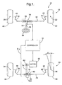
- a vehicle 10 having a front steering system 12, a rear steering system 14, and a control computer 16.
- the vehicle 10 utilizes both the front steering system 12 and the rear steering system 14 to steer the wheels of vehicle 10.
- the front and rear steering systems 12, 14 have a rack and pinion steering configuration.
- the vehicle 10 can have other steering configurations including an integral gear steering configuration, for example.
- the front steering system 12 is provided to control a steering direction of the front wheels 48, 50.
- the system 12 includes a rack shaft 30, a steering rack 32, a pinion gear 34, a steering column 36, a steering wheel 38, tie rods 40, 42, knuckle arms 44, 46, front vehicle wheels 48, 50, and a steering column position sensor 52.
- the rack shaft 30 is operably coupled to tie rods 40, 42 at opposite ends of the rack shaft 30.
- the rack shaft 30 includes a steering rack 32 operably coupled to a pinion gear 34.
- the pinion gear 34 is operably coupled to a steering column 36 that is rotated via a steering wheel 38.
- the tie rod 40 is operably coupled to the knuckle arm 44 that is further operably coupled to the vehicle wheel 48.
- the tie rod 42 is operably coupled to the knuckle arm 46 that is further coupled to the vehicle wheel 50.
- the steering column 36 urges the pinion gear 34 to move the steering rack 32 in a first linear direction relative to a body of the motor vehicle 10.
- the tie rods 40, 42 and the knuckle arms 44, 46 induce the vehicle wheels 48, 52 to turn in a first direction about steering axes 20, 22 associated with the vehicle wheels 48, 52, respectively.
- the steering column 36 urges the pinion gear 34 to move the steering rack 32 in a second linear direction, opposite the first linear direction, relative to the body of the motor vehicle 10.
- the tie rods 40, 42 and the knuckle arms 44, 46 induce the vehicle wheels 48, 52 to turn in a second direction about steering axes 20, 22 associated with the vehicle wheels 48, 52, respectively.
- the steering column sensor 52 is operably coupled to the steering column 36 and is provided to generate a signal indicative of a desired front vehicle wheel steering angle and a desired rear vehicle wheel angle ( ⁇ D ).
- ⁇ D a desired rear vehicle wheel angle
- the desired rear vehicle wheel steering angle can have a different value than the front vehicle wheel steering angle depending upon a vehicle speed, a desired roll angle of the vehicle, and a desired yaw angle of the vehicle.
- the rear steering system 14 is provided to control a steering direction of the rear wheels 94, 96.
- the system 14 includes a motor 60, a drive mechanism 74, a pinion 76, a rack shaft 78, a steering rack 80, a rear wheel alignment spring 82, tie rods 84, 86, knuckle arms 88, 90, vehicle wheels 94, 96, a voltage source 98, an inverter circuit 100, a motor position and velocity sensor 102, and a rear wheel steering angle sensor 104.
- the motor 60 is controlled to provide a desired torque for rotating the rear vehicle wheels 94, 96 to a desired rear vehicle wheel steering angle ( ⁇ D ).
- the motor 60 comprises a 3-phase brushless electrical motor.
- the number of electrical phases of the motor 60 could be less than or greater than 3-phases.
- the motor 60 could comprise other types of electrical motors, such as a switched-reluctance motor for example.
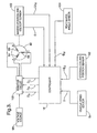
- the motor 60 includes a motor shaft 62, and phase windings 64, 66, 68 operably coupled together in a Y-configuration. As shown, the motor 60 is operably coupled to an inverter circuit 100.
- the inverter circuit 100 energizes the phase windings 64, 66, 68 by pulse-width modulating three sinusoidal voltage waveform applied to phase windings 64, 66, 68 to induce the motor shaft 62 to rotate in either a first rotational direction or a second rotational direction opposite the first rotational direction.
- the controller 16 is operably coupled to the inverter circuit 100 and induces the inverter circuit 102 to generate the pulse-width modulation signals, as will be explained in greater detail below.
- the rotor 62 of motor 60 is operably coupled to the drive mechanism 74.
- the drive mechanism 74 through the pinion 76 transfers the rotational motion of the rotor shaft 62 to a linear motion of the steering rack 80 and the rackshaft 78.
- the rack shaft 78 is operably coupled to the tie rods 84, 86 that are further operably coupled to the knuckle arms 88, 90, respectively.
- the knuckle arms 88, 90 are operably coupled to the rear vehicle wheels 94, 96 respectively.
- the tie rods 84, 86 and the knuckle arms 88, 90 induce the vehicle wheels 94, 96, respectively, to turn in a first predetermined direction about steering axes 24, 26, respectively, associated with the vehicle wheels 94, 96, respectively, toward a desired rear vehicle wheel steering angle ( ⁇ D ).
- ⁇ D desired rear vehicle wheel steering angle
- the rack shaft 78 is moved in a second linear direction, opposite the first linear direction, relative to a body of the motor vehicle 10.
- the tie rods 84, 86 and the knuckle arms 88, 90 induce the vehicle wheels 94, 96, respectively, to turn in a second predetermined direction about steering axes 24, 26, respectively, associated with the vehicle wheels 94, 96, respectively, toward a desired rear vehicle wheel steering angle ( ⁇ D ).
- the rear wheel alignment spring 82 is operably coupled to the steering rack 80 and provides a force that returns the rear steering rack 80 to a center, or neutral position under certain conditions in the rear steering system 14.
- the return spring 82 is disposed in the steering rack 80 with a bi-directional preload.
- the preload is configured to urge the steering rack 82 to the center position when the motor 60 is not maintaining a particular position. It should be noted that when the rear steering rack 80 is displaced from the center position, the force required to displace the rear steering rack 80 is not directionally symmetrical. That is, a displacement in the direction of further compression of the alignment spring 82 (e.g. against the alignment spring 82) will require additional force, as the displacement is opposed by the spring force of the spring 82. Alternately, a displacement in the direction of extension of the alignment spring 82 (e.g. with the alignment spring 82) will require less force, as the displacement is aided by the spring force of spring 82.
- the motor position and velocity sensor 102 is provided to generate: (i) a first signal indicative of an electrical phase position ( ⁇ ) of at least one phase winding of the motor 60, and (ii) a second signal indicative of a rotational speed ( ⁇ m) of the rotor 62.
- the sensor 102 transmits the first and second signals to the controller 16.
- the rear wheel steering angle sensor 104 is provided to generate a signal indicative of a measured rear vehicle wheel steering angle ( ⁇ M ). As shown, the sensor 104 is operably coupled to the steering rack 80 and to the controller 16.
- the vehicle speed sensor 54 is provided to generate a signal indicative of a vehicle speed that is recovered by the controller 16.
- the voltage source 98 is operably coupled to the inverter circuit 100 and supplies a predetermined DC voltage to the inverter circuit 100.
- the voltage source 98 comprises a car battery generating a 12 VDC voltage.
- the voltage source 98 could produce a voltage is greater than or less than 12 Vdc.
- the controller 16 provides control signals to the front steering system 12 and to the rear steering system 14 to control a steering direction of the front vehicle wheels 48, 50, and the rear vehicle wheels 94, 96.
- the controller 16 is operably coupled to the inverter circuit 100, the motor position and velocity sensor 102, the rear wheel steering angle sensor 104, and the steering column position sensor 52.
- the controller 16 receives a signal indicative of the electrical phase position ( ⁇ ) and a signal indicative of the motor rotational speed ( ⁇ m) from the sensor 102, a signal indicative of the measured vehicle wheel steering angle ( ⁇ M ) from the sensor 104, and a signal indicative of the desired vehicle wheel steering angle ( ⁇ D ) from the sensor 52.
- the controller 16 generates control signals for controlling the motor 60 utilizing: (i) the motor rotational speed ( ⁇ m), (ii) the measured vehicle wheel angle ( ⁇ M ), (iii) the desired vehicle wheel angle ( ⁇ D ), as will be discussed in greater detail below.
- the controller 16 includes computer software stored in at least one memory for executing steps corresponding to the following method.
- An advantage of the method is that during predetermined operating conditions, the controller 16 can phase advance voltage waveforms applied to the motor 60 to increase a rotational speed of the motor 60 which results in the wheels 94, 96 being moved toward a desired rear vehicle wheel steering angle ( ⁇ D ) more quickly.
- the controller 16 determines a desired rear vehicle wheel angle ( ⁇ D ) based on a position of a steering wheel 38 and a vehicle speed. It should be noted that a plurality of additional vehicle parameters can be utilized to determine the desired rear vehicle wheel steering angle ( ⁇ D ).
- the controller 16 receives a signal indicative of a measured rear vehicle wheel steering angle ( ⁇ M ) from the rear wheel steering angle sensor 104.
- the controller 16 calculates a spring direction of a rear wheel alignment spring 82 based on the desired rear vehicle wheel steering angle ( ⁇ D ) and the measured rear vehicle wheel steering angle ( ⁇ M ).
- step 148 the controller 16 makes a determination as to whether movement from desired wheel steering angle ( ⁇ D ) to the measured wheel steering angle ( ⁇ M ) would be in a direction opposite a biasing direction of rear wheel alignment spring 82. If the value of step 148 equals "yes", the method advances to step 150. Otherwise, the method advances to step 152.
- the controller 16 calculates a voltage command (VCOM) based on a first gain function (G1), the voltage command (VCOM) having a sign indicated by the position error value (PERR).
- the sign of the position error value (PERR) can either be a plus (i.e., "+") sign or a negative (i.e., "-") sign.
- the first gain function (G1) can be mathematically represented as a quadratic function having a plurality of vehicle operational variables.
- step 152 the controller 16 makes a determination as to whether movement from desired wheel angle ( ⁇ D ) to measured wheel angle ( ⁇ M ) would be in a same direction as a biasing direction of rear wheel alignment spring 82. If the value of step 152 equals "yes", the method advances to step 154. Otherwise, the method advances to step 156.
- the controller 16 calculates a voltage command (VCOM) based on a second gain function (G2), the voltage command (VCOM) having a sign indicated by the position error value (PERR).
- the second gain function (G2) can be mathematically represented as a quadratic function having a plurality of vehicle operational variables.
- the controller 16 calculates a maximum voltage (VMAX) that can be supplied by a voltage source 98 to the motor 60.
- the value of (Ke * ⁇ m ) is indicative of a back emf voltage generated in a phase winding. Further, the value of ( Im ⁇ ax * R * 3 / 4 * ( 1 + ⁇ e * L / R ) 2 ) is indicative of a maximum voltage loss across a phase winding when a maximum output current (Imax) is flowing through the phase winding.
- step 158 the controller 16 makes a determination as to whether the voltage command (VCOM) is greater than the maximum voltage (VMAX). If the value of step 158 equals "yes", the method advances to step 160. Otherwise, the method advances to step 162.
- the controller 16 sets the voltage command (VCOM) equal to the value (VMAX). In other words, the controller 16 limits the commanded voltage command to a maximum voltage that can be provided to the phase windings of the motor 60 by the voltage source 98.
- step 166 the controller 16 determines whether the motor 60 is in a motoring mode of operation based on a sign of the voltage command (VCOM) and a direction of rotation of the rotor 62 of the motor 60, wherein phase advancing voltage waveforms applied to the phase windings in the motor 60 would result in increased rotational speed at a desired torque. If the value of step 166 equals "yes”, the method advances to step 168. Otherwise, the method advances to step 174.
- VCOM sign of the voltage command
- the controller 16 calculates a phase advance angle ( ⁇ ) by solving the following equation where the only unknown value is the phase advance angle ( ⁇ ): (
- ⁇ MAX tan -1 ( ⁇ e * L / R ).
- the controller 16 calculates the phase advanced voltage waveforms (VAB), (VBC) (VCA) for the phase windings 64, 66, 68, respectively, of the motor 60 based on the voltage command (VCOM), and the phase advance angle ( ⁇ ), and an phase angle ( ⁇ ) of the motor.
- VAB phase advanced voltage waveforms
- VBC voltage waveforms
- VCA phase advance angle
- ⁇ phase angle
- phase advanced sinusoidal waveforms VAB
- VBC phase advanced sinusoidal waveforms
- VCA phase advanced sinusoidal waveforms
- the controller 16 generates pulse-width modulated signals (DA, (DB), (DC) based on the phase advanced sinusoidal voltage waveforms (VAB), (VBC), (VCA), respectively, to induce the motor 60 to rotate the rotor 62 at an increased speed having a desired torque.
- the rotor 62 induces a steering actuator to move at least one of the rear vehicle wheels 94, 96 to the desired rear vehicle wheel steering angle ( ⁇ D ).
- the steering actuator comprises the steering rack 82.
- the steering actuator can comprise any device capable of moving at least one of the wheels 94, 96 about a steering axis associated with the wheel.
- the controller 16 determines the sinusoidal voltage waveforms (VAB), (VBC) (VCA) for phase windings 64, 66, 68, respectively, of the motor 60 based on the voltage command (VCOM), and an phase angle ( ⁇ ) of the motor 60.
- VAB VCOM * SIN ( ⁇ )
- VBC VCOM ⁇ SIN ( ⁇ + 120 ° )
- VCA VCOM ⁇ SIN ( ⁇ + 240 ° )
- the controller 16 At step 176, the controller 16 generates pulse-width modulated signals (DA, (DB), (DC) based on the voltage waveforms (VAB), (VBC), (VCA), respectively, to induce the motor 60 to rotate the rotor 62.
- the rotor 62 inducing a steering actuator to move at least one rear vehicle wheel to the desired rear vehicle wheel steering angle ( ⁇ D ).
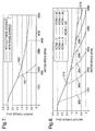
- the curve 190 indicates the operation of the motor 60 when the voltage waveforms applied to the phase windings of the motor 60 are phase advanced. As shown, the rotational speed of the motor 60 is within the range of 0-5000 rpm when phase advancing the voltage waveforms in accordance with exemplary embodiment.
- the curve 192 indicates the operation of the motor 60 when the voltage waveforms applied to the phase windings of motor 60 are not phase advanced. With no phase advancing, a rotational speed of the motor 60 is within a range of 0-2200 rpm.
- phase advancing the voltage waveforms applied to the phase windings of the motor 60 allows a rotational speed of the motor 60 to be dramatically increased.
- a speed of movement of the wheels 94, 96 toward a desired rear vehicle wheel steering angle ( ⁇ D ) is increased.
- FIG. 8 an exemplary motor-torque versus motor-speed plot that indicates a predicted operation of motor 60 with varying voltage commands (VCOM) is illustrated.
- VCOM voltage commands
- the plot illustrates operational curves 200, 202, 204, 206, 208, 210, 212 associated with a voltage command of 5 volts, 10 volts, 15 volts, 20 volts, 25 volts, 30 volts, 100 volts, respectively.
- the plot indicates that as a value of the voltage command increases, the motor speed ( ⁇ m) also increases.
- the system and the method for controlling a steering position of the least one rear wheel of a vehicle provide a substantial advantage over other systems and methods.
- the system and method provide a technical effect of phase advancing voltage waveforms applied to a motor of a rear steering system to increase a turning speed of a rear wheel about a steering axis toward a desired rear wheel steering angle.
- the present invention can be embodied in the form of computer-implemented processes and apparatuses for practicing those processes.
- the present invention can also be embodied in the form of computer program code containing instructions embodied in tangible media, such as floppy diskettes, CD ROMs, hard drives, or any other computer-readable storage medium, wherein, when the computer program code is loaded into and executed by a computer, the computer becomes an apparatus for practicing the invention.
- the present invention can also be embodied in the form of computer program code, for example, whether stored in a storage medium, loaded into and/or executed by a computer, or transmitted over some transmission medium, loaded into and/or executed by a computer, or transmitted over some transmission medium, such as over electrical wiring or cabling, through fiber optics, or via electromagnetic radiation, wherein, when the computer program code is loaded into an executed by a computer, the computer becomes an apparatus for practicing the invention.
- the computer program code segments configure the microprocessor to create specific logic circuits.
Landscapes
- Engineering & Computer Science (AREA)
- Physics & Mathematics (AREA)
- Mathematical Physics (AREA)
- Chemical & Material Sciences (AREA)
- Combustion & Propulsion (AREA)
- Transportation (AREA)
- Mechanical Engineering (AREA)
- Theoretical Computer Science (AREA)
- Steering Control In Accordance With Driving Conditions (AREA)
- Steering-Linkage Mechanisms And Four-Wheel Steering (AREA)
Abstract
Description
- The present application relates to a system and a method for controlling a steering position of at least one rear vehicle wheel.
- In vehicular applications, a typical four-wheel steering system steers the front and the rear wheels of a vehicle. The four-wheel steering system includes a front wheel steering system for steering a set of front wheels and a rear wheel steering system for steering a set of rear wheels. The rear wheel steering system utilizes a motor that induces movement of the rear wheels about vertical wheel axes.
- However, a speed of the motor and a resulting speed that the rear wheels are moved about the wheel axes, can be limited by the voltage supplied by a voltage source to the motor. Thus, when a commanded voltage for a motor is greater than that which can be supplied by the voltage source, the motor moves the rear wheels at a speed limited by the voltage supplied by the voltage source to the motor.
- Thus, there is a need for a rear wheel steering system that can increase a speed at which a motor moves the rear wheels of a vehicle at a desired torque.
- A method for controlling a steering position of at least one rear wheel of a vehicle in accordance with an exemplary embodiment is provided. The vehicle has both a brushless electric motor with a plurality of electrical phase windings and a steering actuator. The brushless electric motor has a rotor configured to drive the steering actuator. The steering actuator is operably coupled to at least one rear vehicle wheel. The method includes determining a desired voltage value indicative of about one-half of a peak-to-peak voltage to be applied to each of the plurality of electrical phase windings of the brushless electric motor based on a desired rear vehicle wheel steering angle and a measured rear vehicle wheel steering angle. The method further includes determining when the desired voltage value is greater than a threshold voltage level. The method further includes calculating a phase advance angle based on at least the desired voltage value and the threshold voltage level. The method further includes phase advancing a plurality of voltage waveforms applied to the plurality of electrical phase windings, wherein each phase advanced voltage waveform is phase advanced an amount substantially equal to the phase advance angle, wherein phase advancing the voltage waveforms increases a speed of the rotor at a desired torque to thereby increase a speed at which the steering actuator moves at least one rear vehicle wheel toward the desired rear vehicle wheel steering angle.
- A system for controlling a steering position of at least one rear wheel of a vehicle in accordance with another exemplary embodiment is provided. The system includes a brushless electric motor having a plurality of electrical phase windings and a rotor. The system further includes an actuator operably coupled to the brushless electric motor, wherein the actuator is configured to move at least one rear vehicle wheel in response to rotation of the rotor of the brushless electric motor. The system further includes an inverter circuit configured to energize the plurality of electrical phase windings in the brushless electric motor. The system further includes a controller operably coupled to the inverter circuit. The controller is configured to determine a desired voltage value indicative of about one-half of a peak-to-peak voltage to be applied to each of the plurality of electrical phase windings of the brushless electric motor based on a desired rear vehicle wheel steering angle and a measured rear vehicle wheel steering angle. The controller is further configured to determine when the desired voltage value is greater than a threshold voltage level. The controller is further configured to calculate a phase advance angle based on at least the desired voltage value and the threshold voltage level. The controller is further configured to induce the inverter circuit to phase advance a plurality of voltage waveforms applied to the plurality of electrical phase windings, wherein each phase advanced voltage waveform is phase advanced an amount substantially equal to the phase advance angle, wherein phase advancing the voltage waveforms increases a speed of the rotor at a desired torque to thereby increase a speed at which the steering actuator moves at least one rear vehicle wheel toward the desired rear vehicle wheel steering angle.
- An article of manufacture in accordance with another exemplary embodiment is provided. The article of manufacture includes a computer storage medium having a computer program encoded therein for controlling a steering position of at least one rear wheel of a vehicle. The vehicle has both a brushless electric motor with a plurality of electrical phase windings and a steering actuator. The brushless electric motor has a rotor configured to drive the steering actuator. The steering actuator is operably coupled to at least one rear vehicle wheel. The computer storage medium includes code for determining a desired voltage value indicative of about one-half of a peak-to-peak voltage to be applied to each of the plurality of electrical phase windings of the brushless electric motor based on a desired rear vehicle wheel steering angle and a measured rear vehicle wheel steering angle. The computer storage medium further includes code for determining when the desired voltage value is greater than a threshold voltage level. The computer storage medium further includes code for calculating a phase advance angle based on at least the desired voltage value and the threshold voltage level. The computer storage medium further includes code for phase advancing a plurality of voltage waveforms applied to the plurality of electrical phase windings, wherein each phase advanced voltage waveform is phase advanced an amount substantially equal to the phase advance angle, wherein phase advancing the voltage waveforms increases a speed of the rotor at a desired torque to thereby increase a speed at which the steering actuator moves at least one rear vehicle wheel toward the desired rear vehicle wheel steering angle.
-
- Figure 1 is a schematic of a vehicle having a front steering system and a rear steering system;
- Figure 2 is a schematic of a portion of the rear steering system of the vehicle;
- Figure 3 is a block diagram of a portion of the rear steering system of the vehicle;
- Figures 4-6 are flowcharts of a method for controlling a steering position of the least one rear wheel of the vehicle;
- Figure 7 is a plot indicating operation of a motor of the rear steering system of Figure 3 with phase advance operation and without phase advance operation; and
- Figure 8 is a plot indicating operation of the motor of the rear steering system of Figure 3 with phase advance operation.
- Referring to Figure 1, a
vehicle 10 is illustrated having afront steering system 12, arear steering system 14, and acontrol computer 16. Thevehicle 10 utilizes both thefront steering system 12 and therear steering system 14 to steer the wheels ofvehicle 10. In the illustrated embodiment, the front andrear steering systems vehicle 10 can have other steering configurations including an integral gear steering configuration, for example. - The
front steering system 12 is provided to control a steering direction of thefront wheels system 12 includes arack shaft 30, asteering rack 32, apinion gear 34, asteering column 36, asteering wheel 38,tie rods knuckle arms front vehicle wheels column position sensor 52. Therack shaft 30 is operably coupled totie rods rack shaft 30. Therack shaft 30 includes asteering rack 32 operably coupled to apinion gear 34. Thepinion gear 34 is operably coupled to asteering column 36 that is rotated via asteering wheel 38. Thetie rod 40 is operably coupled to theknuckle arm 44 that is further operably coupled to thevehicle wheel 48. Thetie rod 42 is operably coupled to theknuckle arm 46 that is further coupled to thevehicle wheel 50. - When the
steering wheel 38 is rotated in a first rotational direction, thesteering column 36 urges thepinion gear 34 to move thesteering rack 32 in a first linear direction relative to a body of themotor vehicle 10. In response, thetie rods knuckle arms vehicle wheels steering axes vehicle wheels steering wheel 38 is rotated in a second rotational direction, thesteering column 36 urges thepinion gear 34 to move thesteering rack 32 in a second linear direction, opposite the first linear direction, relative to the body of themotor vehicle 10. In response, thetie rods knuckle arms vehicle wheels steering axes vehicle wheels - The
steering column sensor 52 is operably coupled to thesteering column 36 and is provided to generate a signal indicative of a desired front vehicle wheel steering angle and a desired rear vehicle wheel angle (ΦD). Of course the desired rear vehicle wheel steering angle can have a different value than the front vehicle wheel steering angle depending upon a vehicle speed, a desired roll angle of the vehicle, and a desired yaw angle of the vehicle. - The
rear steering system 14 is provided to control a steering direction of therear wheels system 14 includes amotor 60, adrive mechanism 74, apinion 76, arack shaft 78, asteering rack 80, a rearwheel alignment spring 82,tie rods knuckle arms vehicle wheels voltage source 98, aninverter circuit 100, a motor position andvelocity sensor 102, and a rear wheelsteering angle sensor 104. - Referring to Figures 1 and 3, the
motor 60 is controlled to provide a desired torque for rotating therear vehicle wheels motor 60 comprises a 3-phase brushless electrical motor. Of course, in alternate embodiments, the number of electrical phases of themotor 60 could be less than or greater than 3-phases. Further, in alternate embodiments themotor 60 could comprise other types of electrical motors, such as a switched-reluctance motor for example. Themotor 60 includes amotor shaft 62, andphase windings motor 60 is operably coupled to aninverter circuit 100. Theinverter circuit 100 energizes thephase windings phase windings motor shaft 62 to rotate in either a first rotational direction or a second rotational direction opposite the first rotational direction. Thecontroller 16 is operably coupled to theinverter circuit 100 and induces theinverter circuit 102 to generate the pulse-width modulation signals, as will be explained in greater detail below. - Referring to Figures 1 and 2, the
rotor 62 ofmotor 60 is operably coupled to thedrive mechanism 74. Thedrive mechanism 74 through thepinion 76 transfers the rotational motion of therotor shaft 62 to a linear motion of thesteering rack 80 and therackshaft 78. Therack shaft 78 is operably coupled to thetie rods knuckle arms knuckle arms rear vehicle wheels motor shaft 62 rotates in a first rotational direction, therack shaft 78 is moved in a first linear direction relative to a body of themotor vehicle 10. In response, thetie rods knuckle arms vehicle wheels axes vehicle wheels motor shaft 62 rotates in a second rotational direction, therack shaft 78 is moved in a second linear direction, opposite the first linear direction, relative to a body of themotor vehicle 10. In response, thetie rods knuckle arms vehicle wheels axes vehicle wheels - The rear
wheel alignment spring 82 is operably coupled to thesteering rack 80 and provides a force that returns therear steering rack 80 to a center, or neutral position under certain conditions in therear steering system 14. Thereturn spring 82 is disposed in thesteering rack 80 with a bi-directional preload. The preload is configured to urge thesteering rack 82 to the center position when themotor 60 is not maintaining a particular position. It should be noted that when therear steering rack 80 is displaced from the center position, the force required to displace therear steering rack 80 is not directionally symmetrical. That is, a displacement in the direction of further compression of the alignment spring 82 (e.g. against the alignment spring 82) will require additional force, as the displacement is opposed by the spring force of thespring 82. Alternately, a displacement in the direction of extension of the alignment spring 82 (e.g. with the alignment spring 82) will require less force, as the displacement is aided by the spring force ofspring 82. - Referring to Figure 3, the motor position and
velocity sensor 102 is provided to generate: (i) a first signal indicative of an electrical phase position (θ) of at least one phase winding of themotor 60, and (ii) a second signal indicative of a rotational speed (ωm) of therotor 62. Thesensor 102 transmits the first and second signals to thecontroller 16. - The rear wheel
steering angle sensor 104 is provided to generate a signal indicative of a measured rear vehicle wheel steering angle (ΦM). As shown, thesensor 104 is operably coupled to thesteering rack 80 and to thecontroller 16. - The
vehicle speed sensor 54 is provided to generate a signal indicative of a vehicle speed that is recovered by thecontroller 16. - The
voltage source 98 is operably coupled to theinverter circuit 100 and supplies a predetermined DC voltage to theinverter circuit 100. In one embodiment, thevoltage source 98 comprises a car battery generating a 12 VDC voltage. Of course, in alternate embodiments, thevoltage source 98 could produce a voltage is greater than or less than 12 Vdc. - The
controller 16 provides control signals to thefront steering system 12 and to therear steering system 14 to control a steering direction of thefront vehicle wheels rear vehicle wheels controller 16 is operably coupled to theinverter circuit 100, the motor position andvelocity sensor 102, the rear wheelsteering angle sensor 104, and the steeringcolumn position sensor 52. In particular, thecontroller 16 receives a signal indicative of the electrical phase position (θ) and a signal indicative of the motor rotational speed (ωm) from thesensor 102, a signal indicative of the measured vehicle wheel steering angle (ΦM) from thesensor 104, and a signal indicative of the desired vehicle wheel steering angle (ΦD) from thesensor 52. Thecontroller 16 generates control signals for controlling themotor 60 utilizing: (i) the motor rotational speed (ωm), (ii) the measured vehicle wheel angle (ΦM), (iii) the desired vehicle wheel angle (ΦD), as will be discussed in greater detail below. - Referring to Figures 4-6, a method for controlling a steering position of at least one rear wheel of the
vehicle 10 will now be explained. In the illustrated embodiment, thecontroller 16 includes computer software stored in at least one memory for executing steps corresponding to the following method. An advantage of the method is that during predetermined operating conditions, thecontroller 16 can phase advance voltage waveforms applied to themotor 60 to increase a rotational speed of themotor 60 which results in thewheels - At
step 140, thecontroller 16 determines a desired rear vehicle wheel angle (ΦD) based on a position of asteering wheel 38 and a vehicle speed. It should be noted that a plurality of additional vehicle parameters can be utilized to determine the desired rear vehicle wheel steering angle (ΦD). - At
step 142, thecontroller 16 receives a signal indicative of a measured rear vehicle wheel steering angle (ΦM) from the rear wheelsteering angle sensor 104. - At
step 144, thecontroller 16 calculates a position error value (PERR) based on the desired rear vehicle wheel steering angle (ΦD) and the measured rear vehicle wheel steering angle (ΦM). In particular, thecontroller 16 calculates the position error value (PERR) utilizing the following equation:
- At
step 146, thecontroller 16 calculates a spring direction of a rearwheel alignment spring 82 based on the desired rear vehicle wheel steering angle (ΦD) and the measured rear vehicle wheel steering angle (ΦM). - At
step 148, thecontroller 16 makes a determination as to whether movement from desired wheel steering angle (ΦD) to the measured wheel steering angle (ΦM) would be in a direction opposite a biasing direction of rearwheel alignment spring 82. If the value ofstep 148 equals "yes", the method advances to step 150. Otherwise, the method advances to step 152. - At
step 150, thecontroller 16 calculates a voltage command (VCOM) based on a first gain function (G1), the voltage command (VCOM) having a sign indicated by the position error value (PERR). The sign of the position error value (PERR) can either be a plus (i.e., "+") sign or a negative (i.e., "-") sign. It should be noted that the first gain function (G1) can be mathematically represented as a quadratic function having a plurality of vehicle operational variables. - At
step 152, thecontroller 16 makes a determination as to whether movement from desired wheel angle (ΦD) to measured wheel angle (ΦM) would be in a same direction as a biasing direction of rearwheel alignment spring 82. If the value ofstep 152 equals "yes", the method advances to step 154. Otherwise, the method advances to step 156. - At
step 154, thecontroller 16 calculates a voltage command (VCOM) based on a second gain function (G2), the voltage command (VCOM) having a sign indicated by the position error value (PERR). The second gain function (G2) can be mathematically represented as a quadratic function having a plurality of vehicle operational variables. - At
step 156, thecontroller 16 calculates a maximum voltage (VMAX) that can be supplied by avoltage source 98 to themotor 60. In particular,controller 16 calculates the maximum voltage (VMAX) based on the following equation:
where
Ke corresponds to a motor constant;
ωm corresponds to a rotational speed of a rotor of the motor;
ω e corresponds to an frequency of a voltage waveform being applied to a phase winding of the motor;
Imax corresponds to a maximum current that can be supplied by the voltage source;
R corresponds to a resistance associated with the motor; and
L corresponds to an inductance associated with the motor. - It should be noted that the value of (Ke * ωm ) is indicative of a back emf voltage generated in a phase winding. Further, the value of

- At
step 158, thecontroller 16 makes a determination as to whether the voltage command (VCOM) is greater than the maximum voltage (VMAX). If the value ofstep 158 equals "yes", the method advances to step 160. Otherwise, the method advances to step 162. - At
step 160, thecontroller 16 sets the voltage command (VCOM) equal to the value (VMAX). In other words, thecontroller 16 limits the commanded voltage command to a maximum voltage that can be provided to the phase windings of themotor 60 by thevoltage source 98. - At
step 162, thecontroller 16 calculates a modulation index value (MI) based on the battery voltage (VBAT) and the voltage command (VCOM). In particular, thecontroller 16 calculates the modulation index value MI utilizing the following equation:
- At
step 166, thecontroller 16 determines whether themotor 60 is in a motoring mode of operation based on a sign of the voltage command (VCOM) and a direction of rotation of therotor 62 of themotor 60, wherein phase advancing voltage waveforms applied to the phase windings in themotor 60 would result in increased rotational speed at a desired torque. If the value ofstep 166 equals "yes", the method advances to step 168. Otherwise, the method advances to step 174. - At
step 168, thecontroller 16 calculates a phase advance angle (δ) by solving the following equation where the only unknown value is the phase advance angle (δ):
- At
step 170, thecontroller 16 calculates the phase advanced voltage waveforms (VAB), (VBC) (VCA) for thephase windings motor 60 based on the voltage command (VCOM), and the phase advance angle (δ), and an phase angle (θ) of the motor. In particular, thecontroller 16 calculates the phase angles for each of the waveforms (VAB), (VBC) (VCA) utilizing the following equations:


controller 16 calculates the phase advanced sinusoidal voltage waveforms (VAB), (VBC) (VCA), utilizing the following equations:


- It should be noted that after the phase advanced sinusoidal waveforms (VAB), (VBC) (VCA) are pulse-width modulated and are applied to phase windings of the
motor 60, a back emf voltage in each phase winding is substantially in phase with an electrical current in the phase winding, which induces themotor 60 to increase a rotational speed of therotor 62. - At
step 172, thecontroller 16 generates pulse-width modulated signals (DA, (DB), (DC) based on the phase advanced sinusoidal voltage waveforms (VAB), (VBC), (VCA), respectively, to induce themotor 60 to rotate therotor 62 at an increased speed having a desired torque. Therotor 62 induces a steering actuator to move at least one of therear vehicle wheels steering rack 82. In an alternate embodiment, the steering actuator can comprise any device capable of moving at least one of thewheels step 172, the method is exited. - At
step 174, thecontroller 16 determines the sinusoidal voltage waveforms (VAB), (VBC) (VCA) forphase windings motor 60 based on the voltage command (VCOM), and an phase angle (θ) of themotor 60. In particular, thecontroller 16 determines the voltage waveforms (VAB), (VBC) (VCA), utilizing the following equations:


- At
step 176, thecontroller 16 generates pulse-width modulated signals (DA, (DB), (DC) based on the voltage waveforms (VAB), (VBC), (VCA), respectively, to induce themotor 60 to rotate therotor 62. Therotor 62 inducing a steering actuator to move at least one rear vehicle wheel to the desired rear vehicle wheel steering angle (ΦD). Afterstep 176, method is exited. - Referring to Figure 7, an exemplary motor-torque versus motor-speed plot that indicates a predicted operation of the
motor 60 is illustrated. Thecurve 190 indicates the operation of themotor 60 when the voltage waveforms applied to the phase windings of themotor 60 are phase advanced. As shown, the rotational speed of themotor 60 is within the range of 0-5000 rpm when phase advancing the voltage waveforms in accordance with exemplary embodiment. In contrast, thecurve 192 indicates the operation of themotor 60 when the voltage waveforms applied to the phase windings ofmotor 60 are not phase advanced. With no phase advancing, a rotational speed of themotor 60 is within a range of 0-2200 rpm. Thus, one skilled in the art will recognize that phase advancing the voltage waveforms applied to the phase windings of themotor 60 allows a rotational speed of themotor 60 to be dramatically increased. As a result, a speed of movement of thewheels - Referring to Figure 8, an exemplary motor-torque versus motor-speed plot that indicates a predicted operation of
motor 60 with varying voltage commands (VCOM) is illustrated. It particular, the plot illustratesoperational curves - The system and the method for controlling a steering position of the least one rear wheel of a vehicle provide a substantial advantage over other systems and methods. In particular, the system and method provide a technical effect of phase advancing voltage waveforms applied to a motor of a rear steering system to increase a turning speed of a rear wheel about a steering axis toward a desired rear wheel steering angle.
- As described above, the present invention can be embodied in the form of computer-implemented processes and apparatuses for practicing those processes. The present invention can also be embodied in the form of computer program code containing instructions embodied in tangible media, such as floppy diskettes, CD ROMs, hard drives, or any other computer-readable storage medium, wherein, when the computer program code is loaded into and executed by a computer, the computer becomes an apparatus for practicing the invention. The present invention can also be embodied in the form of computer program code, for example, whether stored in a storage medium, loaded into and/or executed by a computer, or transmitted over some transmission medium, loaded into and/or executed by a computer, or transmitted over some transmission medium, such as over electrical wiring or cabling, through fiber optics, or via electromagnetic radiation, wherein, when the computer program code is loaded into an executed by a computer, the computer becomes an apparatus for practicing the invention. When implemented on a general-purpose microprocessor, the computer program code segments configure the microprocessor to create specific logic circuits.
- While the invention has been described with reference to exemplary embodiments, it will be understood by those skilled in the art that various changes may be made and equivalents may be substituted for elements thereof without departing from the scope of the invention. In addition, many modifications may be made to adapt a particular situation or material to the teachings of the invention without departing from the essential scope thereof.
- Therefore, it is intended that the invention not be limited to the particular embodiments disclosed for carrying out this invention, but that the invention will include all embodiments falling within the scope of the appended claims. Moreover, the use of the terms first, second, etc. do not denote any order or importance, but rather the terms first, second, etc. are used to distinguish one element from another. Furthermore, the use of the terms a, an, etc. do not denote a limitation of quantity, but rather denote the presence of at least one of the referenced item.
Claims (20)
- A method for controlling a steering position of at least one rear wheel (94, 96) of a vehicle (10), the vehicle (10) having both a brushless electric motor (60) with a plurality of electrical phase windings (64, 66, 68) and a steering actuator (74), the brushless electric motor (60) having a rotor (62) configured to drive the steering actuator (74), the steering actuator (74) being operably coupled to at least one rear vehicle wheel (94), comprising:determining a desired voltage value indicative of about one-half of a peak-to-peak voltage to be applied to each of the plurality of electrical phase windings (64, 66, 68) of the brushless electric motor (60) based on a desired rear vehicle wheel steering angle and a measured rear vehicle wheel steering angle;determining when the desired voltage value is greater than a threshold voltage level;calculating a phase advance angle based on at least the desired voltage value and the threshold voltage level; andphase advancing a plurality of voltage waveforms applied to the plurality of electrical phase windings (64, 66, 68), wherein each phase advanced voltage waveform is phase advanced an amount substantially equal to the phase advance angle, wherein phase advancing the voltage waveforms increases a speed of the rotor (62) at a desired torque to thereby increase a speed at which the steering actuator (74) moves at least one rear vehicle wheel (94) toward the desired rear vehicle wheel steering angle.
- The method of claim 1, wherein the threshold voltage level is indicative of a substantially maximum voltage level that can be supplied by a voltage source (98) supplying a voltage to the brushless electric motor (60).
- The method of claim 1, wherein the phase advance angle is within a range of 0-90 electrical degrees.
- The method of claim 1, wherein the phase advance angle is further based on a frequency of at least one of the plurality of voltage waveforms.
- The method of claim 1, wherein a back emf voltage waveform in an electrical phase winding (64) is substantially in phase with an electrical current in the electrical phase winding induced by a voltage waveform, after said phase advancing.
- The method of claim 1, further comprising:determining a back emf voltage value associated with at least one electrical phase winding (64) of the electric motor (60);determining a voltage loss value indicative of a voltage loss in at least one electrical phase winding (64); andmaintaining the desired voltage value at a value less than or equal to a sum of back emf value and the voltage loss value during the phase advancing of the voltage waveforms.
- The method of claim 1, wherein the plurality of voltage waveforms comprise a plurality of sinusoidal voltage waveforms.
- A system for controlling a steering position of at least one rear wheel (94) of a vehicle (10), comprising:a brushless electric motor (60) having a plurality of electrical phase windings (64, 66, 68) and a rotor (62);an actuator (74) operably coupled to the brushless electric motor (60), wherein the actuator (74) is configured to move at least one rear vehicle wheel (94) in response to rotation of the rotor (62) of the brushless electric motor (60);an inverter circuit (100) configured to energize the plurality of electrical phase windings (64, 66, 68) in the brushless electric motor (60); anda controller (16) operably coupled to the inverter circuit (100), the controller (16) configured to determine a desired voltage value indicative of about one-half of a peak-to-peak voltage to be applied to each of the plurality of electrical phase windings (64, 66, 68) of the brushless electric motor (60) based on a desired rear vehicle wheel steering angle and a measured rear vehicle wheel steering angle, the controller (16) further configured to determine when the desired voltage value is greater than a threshold voltage level, the controller (16) further configured to calculate a phase advance angle based on at least the desired voltage value and the threshold voltage level, the controller (16) further configured to induce the inverter circuit (100) to phase advance a plurality of voltage waveforms applied to the plurality of electrical phase windings(64, 66, 68), wherein each phase advanced voltage waveform is phase advanced an amount substantially equal to the phase advance angle, wherein phase advancing the voltage waveforms increases a speed of the rotor (62) at a desired torque to thereby increase a speed at which the steering actuator (74) moves at least one rear vehicle wheel (94) toward the desired rear vehicle wheel steering angle.
- The system of claim 8, wherein the threshold voltage level is indicative of a substantially maximum voltage level that can be supplied by a voltage source (98) supplying a voltage to the brushless electric motor (60).
- The system of claim 8, wherein the phase advance angle is within a range of 0-90 electrical degrees.
- The system of claim 8, wherein the phase advance angle is further based on a frequency of at least one of the plurality of voltage waveforms.
- The system of claim 8, wherein a back emf voltage waveform in an electrical phase winding (64,66, 68) is substantially in phase with an electrical current in the electrical phase winding induced by a voltage waveform, after said phase advancing.
- The system of claim 8, wherein the computer is further configured to determine a back emf voltage value associated with at least one electrical phase winding (64) of the electric motor (60), the computer further configured to determine a voltage loss value indicative of a voltage loss in least one electrical phase winding (64), the computer further configured to maintain the desired voltage value at a value less than or equal to a sum of back emf value and the voltage loss value during the phase advancing of the voltage waveforms.
- The system of claim 8, wherein the plurality of voltage waveforms comprise a plurality of sinusoidal voltage waveforms.
- An article of manufacture, comprising:a computer storage medium having a computer program encoded therein for controlling a steering position of at least one rear wheel of a vehicle (94), the vehicle having both a brushless electric motor (60) with a plurality of electrical phase windings (64, 66, 68) and a steering actuator (74), the brushless electric motor (60) having a rotor (62) configured to drive the steering actuator (74), the steering actuator (74) being operably coupled to at least one rear vehicle wheel (94), the computer storage medium comprising:code for determining a desired voltage value indicative of about one-half of a peak-to-peak voltage to be applied to each of the plurality of electrical phase windings (64, 66, 68) of the brushless electric motor (60) based on a desired rear vehicle wheel steering angle and a measured rear vehicle wheel steering angle;code for determining when the desired voltage value is greater than a threshold voltage level;code for calculating a phase advance angle based on at least the desired voltage value and the threshold voltage level; andcode for phase advancing a plurality of voltage waveforms applied to the plurality of electrical phase windings (64, 66, 68), wherein each phase advanced voltage waveform is phase advanced an amount substantially equal to the phase advance angle, wherein phase advancing the voltage waveforms increases a speed of the rotor (62) at a desired torque to thereby increase a speed at which the steering actuator (74) moves at least one rear vehicle wheel (94) toward the desired rear vehicle wheel steering angle.
- The article of manufacture of claim 15, wherein the threshold voltage level is indicative of a substantially maximum voltage level that can be supplied by a voltage source (98) supplying a voltage to the brushless electric motor (60).
- The article of manufacture of claim 15, wherein the phase advance angle is within a range of 0-90 electrical degrees.
- The article of manufacture of claim 15, wherein the phase advance angle is further based on a frequency of at least one of the plurality of voltage waveforms.
- The article of manufacture of claim 15, wherein a back emf voltage waveform in an electrical phase winding (64) is substantially in phase with an electrical current in the electrical phase winding (64, 66, 68) induced by a voltage waveform, after said phase advancing.
- The article of manufacture of claim 15, wherein the computer storage medium further comprises:code for determining a back emf voltage value associated with at least one electrical phase winding (64) of the electric motor (60);code for determining a voltage loss value indicative of a voltage loss in least one electrical phase winding (64); andcode for maintaining the desired voltage value at a value less than or equal to a sum of back emf value and the voltage loss value during the phase advancing of the voltage waveforms.
Applications Claiming Priority (1)
| Application Number | Priority Date | Filing Date | Title |
|---|---|---|---|
| US10/929,603 US6949901B1 (en) | 2004-08-30 | 2004-08-30 | System and method for controlling a steering position of rear vehicle wheels |
Publications (3)
| Publication Number | Publication Date |
|---|---|
| EP1630072A2 true EP1630072A2 (en) | 2006-03-01 |
| EP1630072A3 EP1630072A3 (en) | 2006-04-12 |
| EP1630072B1 EP1630072B1 (en) | 2009-03-25 |
Family
ID=34992639
Family Applications (1)
| Application Number | Title | Priority Date | Filing Date |
|---|---|---|---|
| EP05076934A Expired - Lifetime EP1630072B1 (en) | 2004-08-30 | 2005-08-23 | System and method for controlling a steering position of rear vehicle wheels |
Country Status (4)
| Country | Link |
|---|---|
| US (1) | US6949901B1 (en) |
| EP (1) | EP1630072B1 (en) |
| AT (1) | ATE426543T1 (en) |
| DE (1) | DE602005013457D1 (en) |
Families Citing this family (5)
| Publication number | Priority date | Publication date | Assignee | Title |
|---|---|---|---|---|
| JP4571444B2 (en) * | 2004-06-15 | 2010-10-27 | 株式会社ショーワ | Electric power steering device for vehicles |
| US7213675B2 (en) * | 2004-09-29 | 2007-05-08 | Delphi Technologies, Inc. | Method and system for anti-static steering for vehicle steering systems |
| JP6198181B2 (en) * | 2015-11-06 | 2017-09-20 | マツダ株式会社 | Vehicle behavior control device |
| DE102018126475A1 (en) * | 2018-10-24 | 2020-04-30 | Knorr-Bremse Systeme für Nutzfahrzeuge GmbH | Actuating mechanism, clutch actuator and gear actuator with improved vibration behavior |
| KR20220164342A (en) * | 2021-06-04 | 2022-12-13 | 현대자동차주식회사 | Reverse steering system |
Family Cites Families (16)
| Publication number | Priority date | Publication date | Assignee | Title |
|---|---|---|---|---|
| JP2679803B2 (en) * | 1988-04-08 | 1997-11-19 | マツダ株式会社 | Vehicle rear wheel steering system |
| DE3915448A1 (en) * | 1988-05-16 | 1989-11-23 | Fuji Heavy Ind Ltd | METHOD FOR REGULATING THE REAR WHEEL STEERING ADJUSTMENT IN A MOTOR VEHICLE WITH FOUR WHEEL STEERING |
| JPH0764262B2 (en) * | 1989-11-22 | 1995-07-12 | マツダ株式会社 | Rear wheel steering system |
| EP0499027A3 (en) * | 1991-01-10 | 1993-03-17 | Nsk Ltd | Four-wheel steering apparatus |
| JPH05131946A (en) * | 1991-11-13 | 1993-05-28 | Toyota Motor Corp | Rear wheel steering control device |
| US5417299A (en) * | 1993-11-29 | 1995-05-23 | Oshkosh Truck Corporation | All-wheel steering systems |
| KR0168817B1 (en) * | 1996-03-29 | 1999-01-15 | 김영귀 | Fail-safe control system of a rear wheel steering system |
| US5992556A (en) * | 1997-04-15 | 1999-11-30 | Trw Inc. | Method and apparatus for damping control of an electric assist steering system with vehicle speed signal loss feature |
| JP2001010518A (en) * | 1999-06-25 | 2001-01-16 | Honda Motor Co Ltd | Vehicle steering control device |
| WO2001020767A1 (en) | 1999-09-17 | 2001-03-22 | Delphi Technologies, Inc. | Low ripple permanent magnet motor control |
| US6498451B1 (en) | 2000-09-06 | 2002-12-24 | Delphi Technologies, Inc. | Torque ripple free electric power steering |
| US6759780B2 (en) | 2001-05-08 | 2004-07-06 | Delphi Technologies, Inc. | Fractional-slot winding motor |
| US6564131B2 (en) | 2001-08-01 | 2003-05-13 | Delphi Technologies, Inc. | Four-wheel steering algorithm with functional and diagnostic states and modes |
| US6640172B2 (en) | 2001-08-01 | 2003-10-28 | Delphi Technologies, Inc. | Dual gain algorithm for four wheel steering system |
| JP3850735B2 (en) * | 2002-02-04 | 2006-11-29 | 株式会社ジェイテクト | Electric power steering device |
| US7157878B2 (en) * | 2002-11-19 | 2007-01-02 | Delphi Technologies, Inc. | Transient compensation voltage estimation for feedforward sinusoidal brushless motor control |
-
2004
- 2004-08-30 US US10/929,603 patent/US6949901B1/en not_active Expired - Fee Related
-
2005
- 2005-08-23 AT AT05076934T patent/ATE426543T1/en not_active IP Right Cessation
- 2005-08-23 DE DE602005013457T patent/DE602005013457D1/en not_active Expired - Lifetime
- 2005-08-23 EP EP05076934A patent/EP1630072B1/en not_active Expired - Lifetime
Non-Patent Citations (1)
| Title |
|---|
| None |
Also Published As
| Publication number | Publication date |
|---|---|
| EP1630072A3 (en) | 2006-04-12 |
| DE602005013457D1 (en) | 2009-05-07 |
| US6949901B1 (en) | 2005-09-27 |
| EP1630072B1 (en) | 2009-03-25 |
| ATE426543T1 (en) | 2009-04-15 |
Similar Documents
| Publication | Publication Date | Title |
|---|---|---|
| EP3756976B1 (en) | Motor control apparatus including steering angle calculation apparatus | |
| US11267506B2 (en) | Driver torque estimation apparatus and steering system including the same | |
| EP1539559B1 (en) | Controlling an assist motor using a blending filter | |
| US6445987B1 (en) | Electric power steering controller and control method | |
| US20190092377A1 (en) | Steer-by-wire system and control method thereof | |
| EP1927529A2 (en) | Systems and Methods for Controlling a Vehicle Steering System | |
| US11511790B2 (en) | Road friction coefficient estimation using steering system signals | |
| US10556619B2 (en) | Steering control apparatus | |
| JP2005225340A (en) | Electric power steering control device | |
| JP2016514640A (en) | Method for controlling torque of vehicle EPS system and vehicle EPS system | |
| CN111746628A (en) | Steering control device | |
| US11124230B2 (en) | Steering controller | |
| EP3647159A1 (en) | Steering control device | |
| EP3480080B1 (en) | Steering control apparatus | |
| US6864662B2 (en) | Electric power assist steering system and method of operation | |
| EP3702244A1 (en) | Steering control device and method for controlling steering device | |
| EP3715218A1 (en) | Steering control device | |
| CN111942462A (en) | Control device for steering apparatus | |
| EP1630072B1 (en) | System and method for controlling a steering position of rear vehicle wheels | |
| US6731085B2 (en) | Method and apparatus for determining motor faults in an electric assist steering system | |
| JP5552744B2 (en) | Electric power steering device | |
| JP2017017829A (en) | Left-and-right wheel independent control device of electric automobile | |
| EP1313637B1 (en) | Method and system for applying return torque in a vehicle power steering system | |
| JP2019189149A (en) | Steering control device | |
| JP3715441B2 (en) | Vehicle steering device |
Legal Events
| Date | Code | Title | Description |
|---|---|---|---|
| PUAI | Public reference made under article 153(3) epc to a published international application that has entered the european phase |
Free format text: ORIGINAL CODE: 0009012 |
|
| PUAL | Search report despatched |
Free format text: ORIGINAL CODE: 0009013 |
|
| AK | Designated contracting states |
Kind code of ref document: A2 Designated state(s): AT BE BG CH CY CZ DE DK EE ES FI FR GB GR HU IE IS IT LI LT LU LV MC NL PL PT RO SE SI SK TR |
|
| AX | Request for extension of the european patent |
Extension state: AL BA HR MK YU |
|
| AK | Designated contracting states |
Kind code of ref document: A3 Designated state(s): AT BE BG CH CY CZ DE DK EE ES FI FR GB GR HU IE IS IT LI LT LU LV MC NL PL PT RO SE SI SK TR |
|
| AX | Request for extension of the european patent |
Extension state: AL BA HR MK YU |
|
| 17P | Request for examination filed |
Effective date: 20061012 |
|
| AKX | Designation fees paid |
Designated state(s): AT BE BG CH CY CZ DE DK EE ES FI FR GB GR HU IE IS IT LI LT LU LV MC NL PL PT RO SE SI SK TR |
|
| GRAP | Despatch of communication of intention to grant a patent |
Free format text: ORIGINAL CODE: EPIDOSNIGR1 |
|
| GRAS | Grant fee paid |
Free format text: ORIGINAL CODE: EPIDOSNIGR3 |
|
| GRAA | (expected) grant |
Free format text: ORIGINAL CODE: 0009210 |
|
| AK | Designated contracting states |
Kind code of ref document: B1 Designated state(s): AT BE BG CH CY CZ DE DK EE ES FI FR GB GR HU IE IS IT LI LT LU LV MC NL PL PT RO SE SI SK TR |
|
| REG | Reference to a national code |
Ref country code: GB Ref legal event code: FG4D |
|
| REG | Reference to a national code |
Ref country code: CH Ref legal event code: EP |
|
| REG | Reference to a national code |
Ref country code: IE Ref legal event code: FG4D |
|
| REF | Corresponds to: |
Ref document number: 602005013457 Country of ref document: DE Date of ref document: 20090507 Kind code of ref document: P |
|
| PG25 | Lapsed in a contracting state [announced via postgrant information from national office to epo] |
Ref country code: LT Free format text: LAPSE BECAUSE OF FAILURE TO SUBMIT A TRANSLATION OF THE DESCRIPTION OR TO PAY THE FEE WITHIN THE PRESCRIBED TIME-LIMIT Effective date: 20090325 Ref country code: SI Free format text: LAPSE BECAUSE OF FAILURE TO SUBMIT A TRANSLATION OF THE DESCRIPTION OR TO PAY THE FEE WITHIN THE PRESCRIBED TIME-LIMIT Effective date: 20090325 Ref country code: FI Free format text: LAPSE BECAUSE OF FAILURE TO SUBMIT A TRANSLATION OF THE DESCRIPTION OR TO PAY THE FEE WITHIN THE PRESCRIBED TIME-LIMIT Effective date: 20090325 |
|
| PG25 | Lapsed in a contracting state [announced via postgrant information from national office to epo] |
Ref country code: SE Free format text: LAPSE BECAUSE OF FAILURE TO SUBMIT A TRANSLATION OF THE DESCRIPTION OR TO PAY THE FEE WITHIN THE PRESCRIBED TIME-LIMIT Effective date: 20090625 Ref country code: LV Free format text: LAPSE BECAUSE OF FAILURE TO SUBMIT A TRANSLATION OF THE DESCRIPTION OR TO PAY THE FEE WITHIN THE PRESCRIBED TIME-LIMIT Effective date: 20090325 Ref country code: PL Free format text: LAPSE BECAUSE OF FAILURE TO SUBMIT A TRANSLATION OF THE DESCRIPTION OR TO PAY THE FEE WITHIN THE PRESCRIBED TIME-LIMIT Effective date: 20090325 Ref country code: AT Free format text: LAPSE BECAUSE OF FAILURE TO SUBMIT A TRANSLATION OF THE DESCRIPTION OR TO PAY THE FEE WITHIN THE PRESCRIBED TIME-LIMIT Effective date: 20090325 |
|
| NLV1 | Nl: lapsed or annulled due to failure to fulfill the requirements of art. 29p and 29m of the patents act | ||
| PG25 | Lapsed in a contracting state [announced via postgrant information from national office to epo] |
Ref country code: BE Free format text: LAPSE BECAUSE OF FAILURE TO SUBMIT A TRANSLATION OF THE DESCRIPTION OR TO PAY THE FEE WITHIN THE PRESCRIBED TIME-LIMIT Effective date: 20090325 |
|
| PG25 | Lapsed in a contracting state [announced via postgrant information from national office to epo] |
Ref country code: CZ Free format text: LAPSE BECAUSE OF FAILURE TO SUBMIT A TRANSLATION OF THE DESCRIPTION OR TO PAY THE FEE WITHIN THE PRESCRIBED TIME-LIMIT Effective date: 20090325 Ref country code: EE Free format text: LAPSE BECAUSE OF FAILURE TO SUBMIT A TRANSLATION OF THE DESCRIPTION OR TO PAY THE FEE WITHIN THE PRESCRIBED TIME-LIMIT Effective date: 20090325 Ref country code: PT Free format text: LAPSE BECAUSE OF FAILURE TO SUBMIT A TRANSLATION OF THE DESCRIPTION OR TO PAY THE FEE WITHIN THE PRESCRIBED TIME-LIMIT Effective date: 20090901 Ref country code: ES Free format text: LAPSE BECAUSE OF FAILURE TO SUBMIT A TRANSLATION OF THE DESCRIPTION OR TO PAY THE FEE WITHIN THE PRESCRIBED TIME-LIMIT Effective date: 20090706 |
|
| PG25 | Lapsed in a contracting state [announced via postgrant information from national office to epo] |
Ref country code: SK Free format text: LAPSE BECAUSE OF FAILURE TO SUBMIT A TRANSLATION OF THE DESCRIPTION OR TO PAY THE FEE WITHIN THE PRESCRIBED TIME-LIMIT Effective date: 20090325 Ref country code: NL Free format text: LAPSE BECAUSE OF FAILURE TO SUBMIT A TRANSLATION OF THE DESCRIPTION OR TO PAY THE FEE WITHIN THE PRESCRIBED TIME-LIMIT Effective date: 20090325 Ref country code: IS Free format text: LAPSE BECAUSE OF FAILURE TO SUBMIT A TRANSLATION OF THE DESCRIPTION OR TO PAY THE FEE WITHIN THE PRESCRIBED TIME-LIMIT Effective date: 20090725 Ref country code: RO Free format text: LAPSE BECAUSE OF FAILURE TO SUBMIT A TRANSLATION OF THE DESCRIPTION OR TO PAY THE FEE WITHIN THE PRESCRIBED TIME-LIMIT Effective date: 20090325 |
|
| PG25 | Lapsed in a contracting state [announced via postgrant information from national office to epo] |
Ref country code: BG Free format text: LAPSE BECAUSE OF FAILURE TO SUBMIT A TRANSLATION OF THE DESCRIPTION OR TO PAY THE FEE WITHIN THE PRESCRIBED TIME-LIMIT Effective date: 20090625 Ref country code: DK Free format text: LAPSE BECAUSE OF FAILURE TO SUBMIT A TRANSLATION OF THE DESCRIPTION OR TO PAY THE FEE WITHIN THE PRESCRIBED TIME-LIMIT Effective date: 20090325 |
|
| PLBE | No opposition filed within time limit |
Free format text: ORIGINAL CODE: 0009261 |
|
| STAA | Information on the status of an ep patent application or granted ep patent |
Free format text: STATUS: NO OPPOSITION FILED WITHIN TIME LIMIT |
|
| 26N | No opposition filed |
Effective date: 20091229 |
|
| PG25 | Lapsed in a contracting state [announced via postgrant information from national office to epo] |
Ref country code: MC Free format text: LAPSE BECAUSE OF NON-PAYMENT OF DUE FEES Effective date: 20090831 |
|
| REG | Reference to a national code |
Ref country code: CH Ref legal event code: PL |
|
| GBPC | Gb: european patent ceased through non-payment of renewal fee |
Effective date: 20090823 |
|
| PG25 | Lapsed in a contracting state [announced via postgrant information from national office to epo] |
Ref country code: CH Free format text: LAPSE BECAUSE OF NON-PAYMENT OF DUE FEES Effective date: 20090831 Ref country code: LI Free format text: LAPSE BECAUSE OF NON-PAYMENT OF DUE FEES Effective date: 20090831 |
|
| PG25 | Lapsed in a contracting state [announced via postgrant information from national office to epo] |
Ref country code: IE Free format text: LAPSE BECAUSE OF NON-PAYMENT OF DUE FEES Effective date: 20090823 |
|
| REG | Reference to a national code |
Ref country code: FR Ref legal event code: TP |
|
| PG25 | Lapsed in a contracting state [announced via postgrant information from national office to epo] |
Ref country code: GR Free format text: LAPSE BECAUSE OF FAILURE TO SUBMIT A TRANSLATION OF THE DESCRIPTION OR TO PAY THE FEE WITHIN THE PRESCRIBED TIME-LIMIT Effective date: 20090626 |
|
| PG25 | Lapsed in a contracting state [announced via postgrant information from national office to epo] |
Ref country code: GB Free format text: LAPSE BECAUSE OF NON-PAYMENT OF DUE FEES Effective date: 20090823 |
|
| PG25 | Lapsed in a contracting state [announced via postgrant information from national office to epo] |
Ref country code: IT Free format text: LAPSE BECAUSE OF FAILURE TO SUBMIT A TRANSLATION OF THE DESCRIPTION OR TO PAY THE FEE WITHIN THE PRESCRIBED TIME-LIMIT Effective date: 20090325 |
|
| PG25 | Lapsed in a contracting state [announced via postgrant information from national office to epo] |
Ref country code: LU Free format text: LAPSE BECAUSE OF NON-PAYMENT OF DUE FEES Effective date: 20090823 |
|
| REG | Reference to a national code |
Ref country code: DE Ref legal event code: R081 Ref document number: 602005013457 Country of ref document: DE Owner name: GM GLOBAL TECHNOLOGY OPERATIONS LLC (N. D. GES, US Free format text: FORMER OWNER: DELPHI TECHNOLOGIES, INC., TROY, US Effective date: 20110412 Ref country code: DE Ref legal event code: R081 Ref document number: 602005013457 Country of ref document: DE Owner name: STEERING SOLUTIONS IP HOLDING CORP., US Free format text: FORMER OWNER: DELPHI TECHNOLOGIES, INC., TROY, US Effective date: 20110412 Ref country code: DE Ref legal event code: R081 Ref document number: 602005013457 Country of ref document: DE Owner name: GM GLOBAL TECHNOLOGY OPERATIONS LLC (N. D. GES, US Free format text: FORMER OWNER: DELPHI TECHNOLOGIES, INC., TROY, MICH., US Effective date: 20110412 Ref country code: DE Ref legal event code: R081 Ref document number: 602005013457 Country of ref document: DE Owner name: STEERING SOLUTIONS IP HOLDING CORP., SAGINAW, US Free format text: FORMER OWNER: DELPHI TECHNOLOGIES, INC., TROY, MICH., US Effective date: 20110412 |
|
| PG25 | Lapsed in a contracting state [announced via postgrant information from national office to epo] |
Ref country code: HU Free format text: LAPSE BECAUSE OF FAILURE TO SUBMIT A TRANSLATION OF THE DESCRIPTION OR TO PAY THE FEE WITHIN THE PRESCRIBED TIME-LIMIT Effective date: 20090926 |
|
| PG25 | Lapsed in a contracting state [announced via postgrant information from national office to epo] |
Ref country code: TR Free format text: LAPSE BECAUSE OF FAILURE TO SUBMIT A TRANSLATION OF THE DESCRIPTION OR TO PAY THE FEE WITHIN THE PRESCRIBED TIME-LIMIT Effective date: 20090325 |
|
| PG25 | Lapsed in a contracting state [announced via postgrant information from national office to epo] |
Ref country code: CY Free format text: LAPSE BECAUSE OF FAILURE TO SUBMIT A TRANSLATION OF THE DESCRIPTION OR TO PAY THE FEE WITHIN THE PRESCRIBED TIME-LIMIT Effective date: 20090325 |
|
| REG | Reference to a national code |
Ref country code: DE Ref legal event code: R082 Ref document number: 602005013457 Country of ref document: DE Representative=s name: MANITZ, FINSTERWALD & PARTNER GBR, DE |
|
| REG | Reference to a national code |
Ref country code: DE Ref legal event code: R082 Ref document number: 602005013457 Country of ref document: DE Representative=s name: MANITZ, FINSTERWALD & PARTNER GBR, DE Effective date: 20121019 Ref country code: DE Ref legal event code: R081 Ref document number: 602005013457 Country of ref document: DE Owner name: STEERING SOLUTIONS IP HOLDING CORP., US Free format text: FORMER OWNER: GM GLOBAL TECHNOLOGY OPERATIONS, INC., DETROIT, US Effective date: 20121019 Ref country code: DE Ref legal event code: R081 Ref document number: 602005013457 Country of ref document: DE Owner name: GM GLOBAL TECHNOLOGY OPERATIONS LLC (N. D. GES, US Free format text: FORMER OWNER: GM GLOBAL TECHNOLOGY OPERATIONS, INC., DETROIT, US Effective date: 20121019 Ref country code: DE Ref legal event code: R081 Ref document number: 602005013457 Country of ref document: DE Owner name: STEERING SOLUTIONS IP HOLDING CORP., SAGINAW, US Free format text: FORMER OWNER: GM GLOBAL TECHNOLOGY OPERATIONS, INC., DETROIT, MICH., US Effective date: 20121019 Ref country code: DE Ref legal event code: R081 Ref document number: 602005013457 Country of ref document: DE Owner name: GM GLOBAL TECHNOLOGY OPERATIONS LLC (N. D. GES, US Free format text: FORMER OWNER: GM GLOBAL TECHNOLOGY OPERATIONS, INC., DETROIT, MICH., US Effective date: 20121019 |
|
| PGFP | Annual fee paid to national office [announced via postgrant information from national office to epo] |
Ref country code: FR Payment date: 20120830 Year of fee payment: 8 Ref country code: DE Payment date: 20120829 Year of fee payment: 8 |
|
| REG | Reference to a national code |
Ref country code: DE Ref legal event code: R082 Ref document number: 602005013457 Country of ref document: DE Representative=s name: MANITZ, FINSTERWALD & PARTNER GBR, DE |
|
| REG | Reference to a national code |
Ref country code: DE Ref legal event code: R081 Ref document number: 602005013457 Country of ref document: DE Owner name: GM GLOBAL TECHNOLOGY OPERATIONS LLC (N. D. GES, US Free format text: FORMER OWNER: GM GLOBAL TECHNOLOGY OPERATIONS LLC (N. D. GES. D. STAATES DELAWARE), DETROIT, US Effective date: 20130313 Ref country code: DE Ref legal event code: R082 Ref document number: 602005013457 Country of ref document: DE Representative=s name: MANITZ, FINSTERWALD & PARTNER GBR, DE Effective date: 20130313 Ref country code: DE Ref legal event code: R081 Ref document number: 602005013457 Country of ref document: DE Owner name: STEERING SOLUTIONS IP HOLDING CORP., US Free format text: FORMER OWNER: GM GLOBAL TECHNOLOGY OPERATIONS LLC (N. D. GES. D. STAATES DELAWARE), DETROIT, US Effective date: 20130313 Ref country code: DE Ref legal event code: R081 Ref document number: 602005013457 Country of ref document: DE Owner name: STEERING SOLUTIONS IP HOLDING CORP., SAGINAW, US Free format text: FORMER OWNER: GM GLOBAL TECHNOLOGY OPERATIONS LLC (N. D. GES. D. STAATES DELAWARE), DETROIT, MICH., US Effective date: 20130313 Ref country code: DE Ref legal event code: R081 Ref document number: 602005013457 Country of ref document: DE Owner name: GM GLOBAL TECHNOLOGY OPERATIONS LLC (N. D. GES, US Free format text: FORMER OWNER: GM GLOBAL TECHNOLOGY OPERATIONS LLC (N. D. GES. D. STAATES DELAWARE), DETROIT, MICH., US Effective date: 20130313 |
|
| PG25 | Lapsed in a contracting state [announced via postgrant information from national office to epo] |
Ref country code: DE Free format text: LAPSE BECAUSE OF NON-PAYMENT OF DUE FEES Effective date: 20140301 |
|
| REG | Reference to a national code |
Ref country code: DE Ref legal event code: R119 Ref document number: 602005013457 Country of ref document: DE Effective date: 20140301 |
|
| REG | Reference to a national code |
Ref country code: FR Ref legal event code: ST Effective date: 20140430 |
|
| PG25 | Lapsed in a contracting state [announced via postgrant information from national office to epo] |
Ref country code: FR Free format text: LAPSE BECAUSE OF NON-PAYMENT OF DUE FEES Effective date: 20130902 |
|
| REG | Reference to a national code |
Ref country code: FR Ref legal event code: CD Owner name: GM GLOBAL TECHNOLOGY OPERATIONS LLC, US Effective date: 20150723 Ref country code: FR Ref legal event code: TQ Owner name: STEERING SOLUTIONS IP HOLDING CORPORATION, US Effective date: 20150723 Ref country code: FR Ref legal event code: TQ Owner name: GM GLOBAL TECHNOLOGY OPERATIONS LLC, US Effective date: 20150723 Ref country code: FR Ref legal event code: CD Owner name: STEERING SOLUTIONS IP HOLDING CORPORATION, US Effective date: 20150723 |