EP1629950A1 - Laser processing robot with a line passage accomodating an optical fiber inside an arm section - Google Patents
Laser processing robot with a line passage accomodating an optical fiber inside an arm section Download PDFInfo
- Publication number
- EP1629950A1 EP1629950A1 EP05017870A EP05017870A EP1629950A1 EP 1629950 A1 EP1629950 A1 EP 1629950A1 EP 05017870 A EP05017870 A EP 05017870A EP 05017870 A EP05017870 A EP 05017870A EP 1629950 A1 EP1629950 A1 EP 1629950A1
- Authority
- EP
- European Patent Office
- Prior art keywords
- laser processing
- optical fiber
- section
- control axis
- laser beam
- Prior art date
- Legal status (The legal status is an assumption and is not a legal conclusion. Google has not performed a legal analysis and makes no representation as to the accuracy of the status listed.)
- Granted
Links
Images


Classifications
-
- B—PERFORMING OPERATIONS; TRANSPORTING
- B23—MACHINE TOOLS; METAL-WORKING NOT OTHERWISE PROVIDED FOR
- B23K—SOLDERING OR UNSOLDERING; WELDING; CLADDING OR PLATING BY SOLDERING OR WELDING; CUTTING BY APPLYING HEAT LOCALLY, e.g. FLAME CUTTING; WORKING BY LASER BEAM
- B23K26/00—Working by laser beam, e.g. welding, cutting or boring
- B23K26/08—Devices involving relative movement between laser beam and workpiece
- B23K26/0869—Devices involving movement of the laser head in at least one axial direction
- B23K26/0876—Devices involving movement of the laser head in at least one axial direction in at least two axial directions
- B23K26/0884—Devices involving movement of the laser head in at least one axial direction in at least two axial directions in at least three axial directions, e.g. manipulators, robots
-
- B—PERFORMING OPERATIONS; TRANSPORTING
- B23—MACHINE TOOLS; METAL-WORKING NOT OTHERWISE PROVIDED FOR
- B23K—SOLDERING OR UNSOLDERING; WELDING; CLADDING OR PLATING BY SOLDERING OR WELDING; CUTTING BY APPLYING HEAT LOCALLY, e.g. FLAME CUTTING; WORKING BY LASER BEAM
- B23K26/00—Working by laser beam, e.g. welding, cutting or boring
- B23K26/02—Positioning or observing the workpiece, e.g. with respect to the point of impact; Aligning, aiming or focusing the laser beam
- B23K26/04—Automatically aligning, aiming or focusing the laser beam, e.g. using the back-scattered light
- B23K26/042—Automatically aligning the laser beam
-
- B—PERFORMING OPERATIONS; TRANSPORTING
- B25—HAND TOOLS; PORTABLE POWER-DRIVEN TOOLS; MANIPULATORS
- B25J—MANIPULATORS; CHAMBERS PROVIDED WITH MANIPULATION DEVICES
- B25J19/00—Accessories fitted to manipulators, e.g. for monitoring, for viewing; Safety devices combined with or specially adapted for use in connection with manipulators
- B25J19/0025—Means for supplying energy to the end effector
- B25J19/0029—Means for supplying energy to the end effector arranged within the different robot elements
- B25J19/0037—Means for supplying energy to the end effector arranged within the different robot elements comprising a light beam pathway, e.g. laser
Definitions
- the present invention relates to a laser processing robot.
- the present invention also relates to a robot system including the laser processing robot.
- an optical fiber can be used as a transmission path for supplying a laser beam from a laser oscillator to a laser processing tool attached to a wrist portion of a robot mechanical section (referred to as a "manipulator" in this application).
- the optical fiber generally has a large minimum-allowable radius-of-curvature and is laid outside the manipulator, as an umbilical member in the form of a cable or a containing conduit, so as to have a certain degree of freedom for maintaining a bending radius larger than the minimum-allowable radius-of-curvature.
Landscapes
- Physics & Mathematics (AREA)
- Optics & Photonics (AREA)
- Engineering & Computer Science (AREA)
- Mechanical Engineering (AREA)
- Plasma & Fusion (AREA)
- Robotics (AREA)
- Laser Beam Processing (AREA)
- Manipulator (AREA)
Abstract
Description
- The present invention relates to a laser processing robot. The present invention also relates to a robot system including the laser processing robot.
- In a laser processing robot system in which an industrial robot carries out a laser processing, it is known that an optical fiber can be used as a transmission path for supplying a laser beam from a laser oscillator to a laser processing tool attached to a wrist portion of a robot mechanical section (referred to as a "manipulator" in this application). In this robot system, the optical fiber generally has a large minimum-allowable radius-of-curvature and is laid outside the manipulator, as an umbilical member in the form of a cable or a containing conduit, so as to have a certain degree of freedom for maintaining a bending radius larger than the minimum-allowable radius-of-curvature. In this arrangement, during a period when the manipulator operates in a laser processing, the laying configuration of the umbilical member considerably varies due to the operation of the manipulator, so that the umbilical member may be excessively pulled to be entangled with the arm section or other peripheral members, or may be excessively loosened to reduce the output power of the laser beam due to a variation in curvature, which may lead to a malfunction in a processing operation.
- In order to solve the problems associated with the optical fiber layout in the laser processing robot system, it is conventionally proposed to accommodate the optical fiber (or the umbilical member) within the arm section of the manipulator. For example, Japanese Patent Publication No. 2606011 (JP-B-2606011) discloses that an optical fiber connected to a laser torch attached to a wrist portion at the distal end of an articulated robot is arranged within a hollow portion of a rotation shaft of an arm having the wrist portion to extend along a rotation axis of the shaft. On the other hand, Japanese Unexamined Patent Publication (Kokai) No. 2003-200376 (JP-A-2003-200376) discloses that a cable for supplying power, signal, material, etc. to an end effector attached to a wrist portion of an industrial robot is introduced into an interior of an arm through an inlet port formed at a lateral side of the arm and is drawn out from an opening formed at a position intersecting the axis of a rotation shaft of the wrist portion to extend to the end effector.
- In the construction as disclosed in JP-B-2606011, the optical fiber is passed through the hollow portion of the rotation shaft from the rear end of the arm having the wrist portion so as to be introduced into the interior of the arm, and then extends directly to the laser torch at the distal end. The laser torch projects from the wrist portion in a direction perpendicular to the axis of the rotation shaft of the arm, so that the optical fiber extends to be bent or turned at generally 90° at a location just before the laser torch. In this construction, it may be difficult to ensure or maintain the minimum-allowable bending radius of the optical fiber at a bent region just before the laser torch. In this connection, although it is possible to ensure the minimum-allowable bending radius of the optical fiber just before the laser torch by increasing the projecting length of the laser torch from the wrist portion, there may be another problem in this measure such that the outer dimensions of the robot, in particular in the region of the end effector, are increased.
- Also, in the construction as disclosed in JP-A-2003-200376, the end effector projects in a direction perpendicular to the axis of the rotation shaft of the wrist portion, so that, in order to maintain the minimum-allowable bending radius of the cable just before the end effector, the wrist portion is formed into a two-branch structure so as to expose a portion of the cable to the outside of the wrist portion. If the cable contains an optical fiber, the exposed portion of the cable may give rise to the above-described problems due to the excessive entanglement or loosening. In this construction, there may also be a problem in that the outer dimensions of the region of the end effector are increased.
- It is an object of the present invention to provide a laser processing robot which can solve the problem of the possible entanglement and/or bending of an optical fiber during a laser processing operation, and thus can effectively suppress an increase in outer dimensions of the robot.
- Another object of the present invention is to provide a safe and easily operable robot system including such a superior laser processing robot.
- To accomplish the above object, the present invention provides a laser processing robot comprising: a manipulator including an arm section having a wrist portion, the manipulator provided with a plurality of control axes; a laser processing tool attached to the wrist portion of the manipulator; an optical fiber for transmitting a laser beam toward the laser processing tool; and a line passage formed inside the arm section of the manipulator and accommodating the optical fiber; wherein the arm section includes: a first member disposed fixedly relative to a first control axis at a side opposite to the wrist portion; and a second member supported on the first member and rotatable about the first control axis, the second member provided at a distal end thereof with the wrist portion; the line passage being formed continuously within the first member and the second member, an optical fiber inlet port of the line passage being provided in the first member and an optical fiber outlet port of the line passage being provided in the wrist portion of the second member; wherein the laser processing tool includes: an attachment section adapted to be attached to the wrist portion and rotatable about a second control axis perpendicular to the first control axis; a nozzle section extending from the attachment section and provided with a laser beam passage extending in a direction intersecting an axial line of the second control axis; and a reflecting section arranged within the attachment section for reflecting a laser beam emitted from the optical fiber and directing the laser beam toward the laser beam passage; and wherein an emitting end face of the optical fiber is positioned between the optical fiber outlet port provided in the wrist portion and the reflecting section of the laser processing tool.
- In the above-described laser processing robot, the emitting end face of the optical fiber may be positioned on the axial line of the second control axis; and an optical axis of the laser beam emitted from the emitting end face may coincide with the axial line of the second control axis.
- Also, the reflecting section of the laser processing tool may define, within the laser beam passage of the nozzle section, an optical axis of the laser beam, generally perpendicular to the axial line of the second control axis, at a position spaced from an axial line of the first control axis.
- The above-described laser processing robot may further comprise an electric motor for pivoting the laser processing tool about the second control axis, and the electric motor may be housed in an interior of the second member of the arm section.
- The present invention also provides a robot system comprising the above-described laser processing robot and a laser oscillator connected to the optical fiber of the laser processing robot.
- The above and other objects, features and advantages of the present invention will become more apparent from the following description of preferred embodiments in connection with the accompanying drawings, wherein:
- Fig. 1 is a schematic view showing a basic configuration of a laser processing robot system according to the present invention;
- Fig. 2A is a front view of a laser processing robot according to an embodiment of the present invention;
- Fig. 2B is a side view of the laser processing robot of Fig. 2A; and
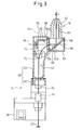
- Fig. 3 is a partially cutaway enlarged view showing the arm section of a manipulator and a laser processing tool, provided in the laser processing robot of Fig. 2A.
- The embodiments of the present invention are described below in detail, with reference to the accompanying drawings. In the drawings, the same or similar components are denoted by common reference numerals.
- Referring to the drawings, Fig. 1 schematically shows the basic configuration of a
laser processing robot 10 and arobot system 12, according to the present invention. Thelaser processing robot 10 includes a manipulator (or a robot mechanical section) 14 provided with a plurality of control axes, acontroller 16 for controlling the operation of themanipulator 14, and alaser processing tool 18 attached to the distal end of themanipulator 14 to act as an end effector. Therobot system 12 is composed by adding alaser oscillator 20 to thelaser processing robot 10. - Between the
laser processing robot 10 and thelaser oscillator 20, anoptical fiber 22 is laid or provided for transmitting a laser beam generated from thelaser oscillator 20 to thelaser processing tool 18. Thecontroller 16 is connected throughcontrol lines 24 to themanipulator 14 and thelaser oscillator 20, and controls the operation of themanipulator 14 as well as the supply of the laser beam from thelaser oscillator 20 through theoptical fiber 22 to thelaser processing tool 18, so as to carry out a desired laser processing on a workpiece W. Theoptical fiber 22 is usually contained in an outer sheath to constitute a cable or, in some cases, be laid in such a state as to be contained in a conduit together with pipelines for an assist gas or cooling water, sensor control cables, and so on. - Figs. 2A and 2B show one embodiment of the
laser processing robot 10 having the above-described basic configuration. In the illustrated embodiment, themanipulator 14 has a structure of a five-axes vertical articulated manipulator, and includes an arm section (so-called a forearm) 28 having awrist portion 26. Themanipulator 14 further includes astationary base 30, and a second arm section (so-called an upper arm) 34 connected through a firstjoint section 32 to thestationary base 30, with thearm section 28 connected through a secondjoint section 36 to thesecond arm section 34. Thefirst joint section 32 connects thesecond arm section 34 to thestationary base 30 in a manner rotatable about a vertical axis (or a control axis) 38 and pivotable about a horizontal axis (or a control axis) 40. Thesecond joint section 36 connects thearm section 28 to thesecond arm section 34 in a manner pivotable about a second horizontal axis (or a control axis) 42 and rotatable about a second vertical axis (or a control axis) 44. Further, thelaser processing tool 18 is joined to thewrist portion 26 of thearm section 28 in a manner pivotable about a third horizontal axis (or a control axis) 46. In the present application, a rotational control axis of thearm section 28, of which the rotation center is the secondvertical axis 44, is referred to as afirst control axis 44, and a pivotal control axis of thelaser processing tool 18, of which the rotation center is the thirdhorizontal axis 46, is referred to as asecond control axis 46 perpendicular to thefirst control axis 44. - More specifically, referring to Fig. 3, the
arm section 28 includes afirst member 48 attached to thesecond joint section 36 and disposed fixedly relative to thefirst control axis 44 at a side opposite to thewrist portion 26, and asecond member 50 supported on thefirst member 48 and rotatable about thefirst control axis 44, thesecond member 50 provided at the distal end thereof with thewrist portion 26. Each of thefirst member 48 and thesecond member 50 is a hollow tubular member, and aline passage 52 is formed continuously inside thefirst member 48 and thesecond member 50. An opticalfiber inlet port 54 for introducing theoptical fiber 22 into theline passage 52 is provided in thefirst member 48 of thearm section 28, so as to open at a lateral side opposite to thesecond arm section 34 with respect to the second joint section 36 (Fig. 2B). An opticalfiber outlet port 56 for drawing out theoptical fiber 22 from theline passage 52 is provided in thewrist portion 26 of thesecond member 50 of thearm section 28, so as to open along the axial line of thesecond control axis 46. - The
laser processing tool 18 includes anattachment section 60 adapted to be attached to thewrist portion 26 of thearm section 28 and pivotable about thesecond control axis 46, the attachment section including acavity 58 communicating with the opticalfiber outlet port 56 of theline passage 52; anozzle section 64 extending integrally from theattachment section 60 and provided with alaser beam passage 62 extending in a direction intersecting the axial line of the second control axis; and a reflectingsection 66 fixedly arranged inside thecavity 58 of theattachment section 60 for reflecting a laser beam L emitted from theoptical fiber 22 and directing the laser beam to thelaser beam passage 62. Theoptical fiber 22 is disposed inside theline passage 52 in a suitably bent form (i.e., with a bending radius not smaller than the minimum-allowable bending radius) in a manner that the emittingend face 22a of theoptical fiber 22 is positioned between the opticalfiber outlet port 56 provided in thewrist portion 26 and the reflectingsection 66 of thelaser processing tool 18. The distal end region, including the emittingend face 22a, of theoptical fiber 22 may be advantageously supported in a fixed manner relative to thewrist portion 26 by a not-shown means and through, for example, ablock member 68. - According to the
laser processing robot 10 having the configuration as described above, theoptical fiber 22 accommodated in theline passage 52 of thewrist portion 28 can maintain a preset suitable bent form (i.e., with a bending radius not smaller than the minimum-allowable bending radius) in theline passage 52 without being substantially affected by the pivoting motion of thelaser processing tool 18 attached to thewrist portion 26. Theoptical fiber 22 is also held within theline passage 52 continuously formed in the first andsecond members arm section 28. Therefore, in a laser processing operation, it is possible to reliably prevent theoptical fiber 22 from being excessively entangled or bent, which may lead to the damage of the fiber or the lowering of the laser beam power, during a period when the orientation of themanipulator 14 is variously changed to direct thenozzle section 64 of thelaser processing tool 18 into a suitable welding orientation relative to the workpiece W (Fig. 1). Further, the laser beam L emitted from theoptical fiber 22 is reflected by the reflectingsection 66 provided in thelaser processing tool 18 in a direction intersecting the axial line of thesecond control axis 46 and is discharged from thenozzle section 64 toward the workpiece W to be irradiated (Fig. 1), so that it is possible to reduce the projecting length of thenozzle section 64 relative to thewrist portion 26 in a direction along thesecond control axis 46, and thus to effectively suppress an increase in dimensions of the end effector region of thelaser processing robot 10. - In the
laser processing robot 10, as shown in Fig. 3, it is advantageous that theemitting end face 22a of theoptical fiber 22 is positioned on the axial line of thesecond control axis 46, and that the optical axis of the laser beam L emitted from the emittingend face 22a coincides with the axial line of thesecond control axis 46, at a location just before the reflectingsection 66 of thelaser processing tool 18. According to this arrangement, during a period when thelaser processing tool 18 operates to pivot about thesecond control axis 46, the optical axis of the laser beam L reflected by the reflectingsection 66 is maintained at the same position in thelaser beam passage 62 of thenozzle section 64, irrespective of a pivoting angle, so that it is possible to facilitate the control of themanipulator 14 in the laser processing operation. - It is also advantageous that, as illustrated, the reflecting
section 66 of thelaser processing tool 18 is constructed to define, within thelaser beam passage 62 of thenozzle section 64, the optical axis of the reflected laser beam L to be generally perpendicular to the axial line of thesecond control axis 46, at a position spaced from the axial line of thefirst control axis 44. According to this arrangement, it is possible to minimize the projecting length of thenozzle section 64 from thewrist portion 28 in a direction along thesecond control axis 46. - As shown in Fig. 3, in the
laser processing robot 10, acoupler shaft member 70, having a U-shaped cross-section, is provided in thewrist portion 26 of thearm section 28. Thecoupler shaft member 70 is one element provided at the output-end side of a power transmission mechanism in the drive mechanism of thesecond control axis 46, and is connected through a belt/pulley unit 74 as the power transmission mechanism to anelectric motor 72 as the drive source of the drive mechanism. The drive mechanism of the second control axis 46 (i.e., thecoupler shaft member 70, theelectric motor 72 and the belt/pulley unit 74) is housed in the interior of thesecond member 50 of thearm section 28 at thewrist portion 26. Thecoupler shaft member 70 has aflange 70a exposed to the outside of alateral opening 50a formed in thesecond member 50 at thewrist portion 26. The opticalfiber outlet port 56 is formed in theflange 70a, and theattachment section 60 of thelaser processing tool 18 is fixed to theflange 70a. Thereby, thelaser processing tool 18 operates for pivot motion, integrally with thecoupler shaft member 70, about thesecond control axis 46 by the output power of theelectric motor 72. - Thus, the drive mechanism of the second control axis 46 (especially, the electric motor 72) is arranged inside the
second member 50 of thearm section 28, so that it is possible to effectively eliminate a projecting portion on the outer surface at thewrist portion 26, and thus to more easily perform the laser processing operation in a narrow space. The U-shaped cross-section of thecoupler shaft member 70 functions so as to effectively prevent interference between thecoupler shaft member 70 and theoptical fiber 22, during the pivoting motion of thelaser processing tool 18. In particular, as illustrated, when theelectric motor 72 is disposed side by side with the coupler shaft member 70 (i.e., the output-side element of the power transmission mechanism) in the interior of thesecond member 50, and the center (or rotation) axes thereof are disposed parallel to each other, it is possible to ensure an ample space to permit theoptical fiber 22 to be displaced freely in the interior of thesecond member 50, during the operation of the manipulator 14 (and especially during the rotation of thearm section 28 about the first control axis 44). - In the
laser processing robot 10, it is advantageous that aholder 76 for holding theoptical fiber 22 is fixedly provided on the outer surface of the secondjoint section 36, near the opticalfiber inlet port 54 provided in thefirst member 48 of thearm section 28. According to this structure, it is possible to suppress the displacement motion of theoptical fiber 22 during the operation of themanipulator 14. - It should be noted that, for example, in place of the arrangement of the illustrated embodiment, in which the optical
fiber inlet port 54 is formed at the lateral side of thefirst member 48 of thearm section 28, a through-hole may be formed in the secondjoint section 36 and the axial end face of thefirst member 48 adjacent thereto, so as to be used as an optical fiber inlet port. Also, in place of the five-axes vertical articulatedmanipulator 14 adopted in the illustrated embodiment, manipulators having various other constructions may be adopted. - As will be clearly understood from the above description, the laser processing robot and the robot system including the same, according to the present invention, can avoid, with a low-cost structure, the excessive entanglement or bending of the optical fiber for transmitting a laser beam and, therefore, can be advantageously utilized as a safe and easily operable industrial robot that is capable of preventing the interference between the optical fiber and the peripheral devices for the robot.
- While the invention has been described with reference to specific preferred embodiments, it will be understood by those skilled in the art that various changes and modifications may be made thereto without departing from the scope of the following claims.
Claims (7)
- A laser processing robot (10) comprising:a manipulator (14) including an arm section (28) having a wrist portion (26), said manipulator provided with a plurality of control axes (38, 40, 42, 44, 46);a laser processing tool (18) attached to said wrist portion of said manipulator;an optical fiber (22) for transmitting a laser beam (L) toward said laser processing tool; anda line passage (52) formed inside said arm section of said manipulator and accommodating said optical fiber;wherein said arm section includes:a first member (48) disposed fixedly relative to a first control axis (44) at a side opposite to said wrist portion; anda second member (50) supported on said first member and rotatable about said first control axis, said second member provided at a distal end thereof with said wrist portion;said line passage being formed continuously within said first member and said second member, an optical fiber inlet port (54) of said line passage being provided in said first member and an optical fiber outlet port (56) of said line passage being provided in said wrist portion of said second member;wherein said laser processing tool includes:an attachment section (60) adapted to be attached to said wrist portion and rotatable about a second control axis (46) perpendicular to said first control axis;a nozzle section (64) extending from said attachment section and provided with a laser beam passage (62) extending in a direction intersecting an axial line of said second control axis; anda reflecting section (66) arranged within said attachment section for reflecting a laser beam emitted from said optical fiber and directing the laser beam toward said laser beam passage; andwherein an emitting end face (22a) of said optical fiber is positioned between said optical fiber outlet port provided in said wrist portion and said reflecting section of said laser processing tool.
- A laser processing robot according to claim 1, wherein said emitting end face of said optical fiber is positioned on said axial line of said second control axis; and wherein an optical axis of said laser beam emitted from said emitting end face coincides with said axial line of said second control axis.
- A laser processing robot according to claim 1, wherein said reflecting section of said laser processing tool defines, within said laser beam passage of said nozzle section, an optical axis of said laser beam, generally perpendicular to said axial line of said second control axis, at a position spaced from an axial line of said first control axis.
- A laser processing robot according to claim 1, further comprising an electric motor (72) for pivoting said laser processing tool about said second control axis, said electric motor being housed in an interior of said second member of said arm section.
- A laser processing robot according to claim 4, further comprising a power transmission mechanism (70, 74) for transmitting an output power of said electric motor to said attachment section of said laser processing tool, said electric motor being disposed in said interior of said second member and side by side with an output-side element (70) of said power transmission mechanism.
- A laser processing robot according to claim 1, wherein said manipulator comprises a five-axes vertical articulated manipulator.
- A robot system comprising a laser processing robot according to claim 1 and a laser oscillator (20) connected to said optical fiber of said laser processing robot.
Applications Claiming Priority (1)
| Application Number | Priority Date | Filing Date | Title |
|---|---|---|---|
| JP2004241490A JP2006055954A (en) | 2004-08-20 | 2004-08-20 | Robot for laser beam machining, and robot system |
Publications (2)
| Publication Number | Publication Date |
|---|---|
| EP1629950A1 true EP1629950A1 (en) | 2006-03-01 |
| EP1629950B1 EP1629950B1 (en) | 2008-04-02 |
Family
ID=35044853
Family Applications (1)
| Application Number | Title | Priority Date | Filing Date |
|---|---|---|---|
| EP05017870A Expired - Fee Related EP1629950B1 (en) | 2004-08-20 | 2005-08-17 | Laser processing robot with a line passage accomodating an optical fiber inside an arm section |
Country Status (5)
| Country | Link |
|---|---|
| US (1) | US7145100B2 (en) |
| EP (1) | EP1629950B1 (en) |
| JP (1) | JP2006055954A (en) |
| CN (1) | CN1736652A (en) |
| DE (1) | DE602005005752T2 (en) |
Cited By (2)
| Publication number | Priority date | Publication date | Assignee | Title |
|---|---|---|---|---|
| EP3470181A1 (en) * | 2017-10-12 | 2019-04-17 | Seiko Epson Corporation | Robot and optical transmission device |
| US11123861B2 (en) | 2018-10-24 | 2021-09-21 | Fanuc Corporation | Robot system |
Families Citing this family (22)
| Publication number | Priority date | Publication date | Assignee | Title |
|---|---|---|---|---|
| KR100800565B1 (en) | 2006-08-31 | 2008-02-04 | 동일파텍주식회사 | High Speed Fiber Laser Processing Equipment |
| US7540666B2 (en) * | 2007-02-27 | 2009-06-02 | Corning Cable Systems Llc | Articulated force application for multi-fiber ferrules |
| SE532695C2 (en) * | 2008-02-25 | 2010-03-16 | Igems Software Ab | Tool holders |
| JP2009217205A (en) * | 2008-03-13 | 2009-09-24 | Panasonic Corp | Method for disassembling display and disassembling device |
| WO2010118769A1 (en) * | 2009-04-15 | 2010-10-21 | Abb Research Ltd | An apparatus for a robot arm |
| US20140324034A1 (en) * | 2011-11-11 | 2014-10-30 | Lumenis Ltd | Systems and methods for facilitating robotic surgical laser procedures |
| AT513222B1 (en) * | 2012-08-03 | 2016-11-15 | Haas Food Equipment Gmbh | Method and device for cleaning baking surfaces |
| CN104117990B (en) * | 2013-04-23 | 2015-12-16 | 中国科学院沈阳自动化研究所 | A kind of robot wrist towards laser precision machining |
| JP6068548B2 (en) * | 2015-04-09 | 2017-01-25 | ファナック株式会社 | An articulated robot in which connecting members for connecting the striatum are arranged on the arm |
| CN105034608A (en) * | 2015-07-10 | 2015-11-11 | 辽宁科技大学 | Industrial robot laser marking machine |
| RU169869U1 (en) * | 2015-12-04 | 2017-04-04 | Закрытое акционерное общество "Балтийская промышленная компания" | INDUSTRIAL ROBOT FOR LASER PROCESSING |
| CN106918357A (en) * | 2015-12-27 | 2017-07-04 | 天津市鑫源泓达科技有限公司 | A kind of sensor fastening device |
| JP6558834B2 (en) * | 2016-09-07 | 2019-08-14 | 株式会社スギノマシン | Laser processing head |
| US20210060764A1 (en) * | 2017-08-31 | 2021-03-04 | Laser Mechanisms, Inc. | Robotic arm end effector |
| JP6572270B2 (en) | 2017-09-08 | 2019-09-04 | ファナック株式会社 | Robot with hollow wrist element |
| JP6975198B2 (en) * | 2018-06-28 | 2021-12-01 | ファナック株式会社 | Laser machining system |
| DE102019128605B4 (en) | 2018-10-24 | 2022-11-03 | Fanuc Corporation | robotic system |
| CN109773349B (en) * | 2018-12-29 | 2020-12-15 | 江苏维力安智能科技有限公司 | Rotating shaft assembly for connecting laser cutting head |
| CN110899971A (en) * | 2019-11-21 | 2020-03-24 | 济南金威刻科技发展有限公司 | Rotary laser welding head |
| CN117241919A (en) * | 2021-04-28 | 2023-12-15 | 发那科株式会社 | robot |
| CN115121553B (en) * | 2022-07-21 | 2024-01-26 | 核工业理化工程研究院 | A laser cleaning system and cleaning method for automatically cleaning walls or tank walls |
| CN224004434U (en) * | 2022-10-11 | 2026-03-17 | 米沃奇电动工具公司 | Laser layout system |
Citations (5)
| Publication number | Priority date | Publication date | Assignee | Title |
|---|---|---|---|---|
| JPH0284290A (en) * | 1988-09-20 | 1990-03-26 | Fanuc Ltd | Wrist construction for laser beam robot |
| EP0428748A1 (en) * | 1989-06-14 | 1991-05-29 | Fanuc Ltd. | Method of preventing erroneous projection of laser beam in a laser robot |
| JP2606011B2 (en) | 1991-07-03 | 1997-04-30 | 松下電器産業株式会社 | Articulated robot |
| US6369353B1 (en) * | 1998-02-20 | 2002-04-09 | The Goodyear Tire & Rubber Company | Robotic laser tire mold cleaning system and method of use |
| JP2003200376A (en) | 2001-10-22 | 2003-07-15 | Yaskawa Electric Corp | Industrial robot |
Family Cites Families (3)
| Publication number | Priority date | Publication date | Assignee | Title |
|---|---|---|---|---|
| US4578554A (en) * | 1984-04-30 | 1986-03-25 | Teledyne, Inc. | Laser welding apparatus |
| CA2489941C (en) * | 2003-12-18 | 2012-08-14 | Comau S.P.A. | A method and device for laser welding |
| ITTO20040193A1 (en) * | 2004-03-23 | 2004-06-23 | Comau Spa | ROBOT FOR THE EXECUTION OF INDUSTRIAL OPERATIONS BY LASER BEAM |
-
2004
- 2004-08-20 JP JP2004241490A patent/JP2006055954A/en active Pending
-
2005
- 2005-08-15 US US11/203,289 patent/US7145100B2/en not_active Expired - Fee Related
- 2005-08-17 EP EP05017870A patent/EP1629950B1/en not_active Expired - Fee Related
- 2005-08-17 DE DE602005005752T patent/DE602005005752T2/en not_active Expired - Lifetime
- 2005-08-19 CN CNA2005100932543A patent/CN1736652A/en active Pending
Patent Citations (5)
| Publication number | Priority date | Publication date | Assignee | Title |
|---|---|---|---|---|
| JPH0284290A (en) * | 1988-09-20 | 1990-03-26 | Fanuc Ltd | Wrist construction for laser beam robot |
| EP0428748A1 (en) * | 1989-06-14 | 1991-05-29 | Fanuc Ltd. | Method of preventing erroneous projection of laser beam in a laser robot |
| JP2606011B2 (en) | 1991-07-03 | 1997-04-30 | 松下電器産業株式会社 | Articulated robot |
| US6369353B1 (en) * | 1998-02-20 | 2002-04-09 | The Goodyear Tire & Rubber Company | Robotic laser tire mold cleaning system and method of use |
| JP2003200376A (en) | 2001-10-22 | 2003-07-15 | Yaskawa Electric Corp | Industrial robot |
Non-Patent Citations (1)
| Title |
|---|
| PATENT ABSTRACTS OF JAPAN vol. 014, no. 277 (M - 0985) 15 June 1990 (1990-06-15) * |
Cited By (3)
| Publication number | Priority date | Publication date | Assignee | Title |
|---|---|---|---|---|
| EP3470181A1 (en) * | 2017-10-12 | 2019-04-17 | Seiko Epson Corporation | Robot and optical transmission device |
| US10574363B2 (en) | 2017-10-12 | 2020-02-25 | Seiko Epson Corporation | Robot and optical transmission device |
| US11123861B2 (en) | 2018-10-24 | 2021-09-21 | Fanuc Corporation | Robot system |
Also Published As
| Publication number | Publication date |
|---|---|
| DE602005005752D1 (en) | 2008-05-15 |
| JP2006055954A (en) | 2006-03-02 |
| EP1629950B1 (en) | 2008-04-02 |
| CN1736652A (en) | 2006-02-22 |
| US20060037950A1 (en) | 2006-02-23 |
| DE602005005752T2 (en) | 2009-05-07 |
| US7145100B2 (en) | 2006-12-05 |
Similar Documents
| Publication | Publication Date | Title |
|---|---|---|
| EP1629950B1 (en) | Laser processing robot with a line passage accomodating an optical fiber inside an arm section | |
| EP1625920B1 (en) | Managing structure for umbilical member of industrial robot | |
| JP4280295B2 (en) | Industrial robot | |
| US6696810B2 (en) | Wrist structure for a robot | |
| EP1531029B1 (en) | Cable distribution and support equipment for sensor in robot system | |
| US11220011B2 (en) | Multi-jointed welding robot | |
| JP6467644B2 (en) | Laser processing robot | |
| US7105771B2 (en) | Torch cable accommodating structure of arc welding robot | |
| EP1892064A1 (en) | Drive mechanism for industrial robot arm | |
| JP2008238320A (en) | Robot having working tool | |
| EP1992457A1 (en) | Robot having arm in which umbilical member is accommodated | |
| JP2003200376A (en) | Industrial robot | |
| CN110234474B (en) | Wire harness connection structure of robot arm and articulated welding robot | |
| JP2004358649A (en) | Industrial robot | |
| EP1602460A1 (en) | Umbilical member managing system for industrial robot | |
| US20190321906A1 (en) | Articulated welding robot | |
| JP2820391B2 (en) | Industrial vertical articulated robot | |
| JPH0255689A (en) | Joint structure of industrial articulated robot for laser apparatus | |
| JP2006281226A (en) | Wire feeder | |
| JPH02303778A (en) | Arm driving mechanism for robot | |
| JPS6115546A (en) | Drive device | |
| EP0411140A1 (en) | Articulated arm type industrial laser robot | |
| CN121240955A (en) | robot | |
| JP3823130B2 (en) | Laser processing machine |
Legal Events
| Date | Code | Title | Description |
|---|---|---|---|
| PUAI | Public reference made under article 153(3) epc to a published international application that has entered the european phase |
Free format text: ORIGINAL CODE: 0009012 |
|
| AK | Designated contracting states |
Kind code of ref document: A1 Designated state(s): AT BE BG CH CY CZ DE DK EE ES FI FR GB GR HU IE IS IT LI LT LU LV MC NL PL PT RO SE SI SK TR |
|
| AX | Request for extension of the european patent |
Extension state: AL BA HR MK YU |
|
| 17P | Request for examination filed |
Effective date: 20060216 |
|
| AKX | Designation fees paid |
Designated state(s): DE |
|
| GRAP | Despatch of communication of intention to grant a patent |
Free format text: ORIGINAL CODE: EPIDOSNIGR1 |
|
| GRAS | Grant fee paid |
Free format text: ORIGINAL CODE: EPIDOSNIGR3 |
|
| GRAA | (expected) grant |
Free format text: ORIGINAL CODE: 0009210 |
|
| AK | Designated contracting states |
Kind code of ref document: B1 Designated state(s): DE |
|
| REF | Corresponds to: |
Ref document number: 602005005752 Country of ref document: DE Date of ref document: 20080515 Kind code of ref document: P |
|
| PLBE | No opposition filed within time limit |
Free format text: ORIGINAL CODE: 0009261 |
|
| STAA | Information on the status of an ep patent application or granted ep patent |
Free format text: STATUS: NO OPPOSITION FILED WITHIN TIME LIMIT |
|
| 26N | No opposition filed |
Effective date: 20090106 |
|
| PGFP | Annual fee paid to national office [announced via postgrant information from national office to epo] |
Ref country code: DE Payment date: 20090814 Year of fee payment: 5 |
|
| REG | Reference to a national code |
Ref country code: DE Ref legal event code: R119 Ref document number: 602005005752 Country of ref document: DE Effective date: 20110301 |
|
| PG25 | Lapsed in a contracting state [announced via postgrant information from national office to epo] |
Ref country code: DE Free format text: LAPSE BECAUSE OF NON-PAYMENT OF DUE FEES Effective date: 20110301 |