EP1629948A1 - Combustion-type power tool having cooling arrangement - Google Patents
Combustion-type power tool having cooling arrangement Download PDFInfo
- Publication number
- EP1629948A1 EP1629948A1 EP05255207A EP05255207A EP1629948A1 EP 1629948 A1 EP1629948 A1 EP 1629948A1 EP 05255207 A EP05255207 A EP 05255207A EP 05255207 A EP05255207 A EP 05255207A EP 1629948 A1 EP1629948 A1 EP 1629948A1
- Authority
- EP
- European Patent Office
- Prior art keywords
- cylinder head
- combustion chamber
- housing
- combustion
- fan
- Prior art date
- Legal status (The legal status is an assumption and is not a legal conclusion. Google has not performed a legal analysis and makes no representation as to the accuracy of the status listed.)
- Granted
Links
Images

Classifications
-
- B—PERFORMING OPERATIONS; TRANSPORTING
- B25—HAND TOOLS; PORTABLE POWER-DRIVEN TOOLS; MANIPULATORS
- B25C—HAND-HELD NAILING OR STAPLING TOOLS; MANUALLY OPERATED PORTABLE STAPLING TOOLS
- B25C1/00—Hand-held nailing tools; Nail feeding devices
- B25C1/08—Hand-held nailing tools; Nail feeding devices operated by combustion pressure
Definitions
- the present invention relates to a combustion-type power tool, and more particularly, to such power tool capable of driving a fastener such as a nail, an anchor, and a staple into a workpiece.
- a conventional combustion-type power tool such as a nail gun
- a mixture of air and gaseous fuel injected into a combustion chamber is ignited by a spark at an ignition plug to cause gas expansion in the combustion chamber, which in turn causes a linear momentum of a piston.
- a nail is driven into a workpiece.
- Such conventional combustion-type nail gun is described in U.S.Patent No. 5,197,646 and Japanese Patent Publication No. H03-25307.
- the present inventors contemplated optimum position of a fan within a combustion chamber so as to provide an optimum air flow and air flow amount for cooling the component such as a cylinder.
- a combustion-type power tool including a housing, a cylinder head, a cylinder, a piston, a push lever, a combustion chamber frame, a driver blade, an ignition plug, and a fan.
- the housing has one end and another end and is formed with an exhaust port
- the cylinder head is disposed at the one end.
- the cylinder is disposed in and fixed to the housing.
- the cylinder defines an axial direction.
- the piston is slidably disposed in the cylinder and reciprocally movable in the axial direction.
- the push lever is disposed at the another end of the housing and movable in the axial direction upon pressing against a workpiece.
- the combustion chamber frame is disposed in the housing and movable in the axial direction.
- the combustion chamber frame includes a base section and a head section.
- the base section is associated with the push lever, and has one end which is a remote side from the push lever.
- the head section is fixed to the one end of the base section and abuttable on the cylinder head.
- the head section includes a disc like connecting portion having a radially outer edge connected to the one end of the base section and having an radially inner edge, and a sleeve like abutment portion extending in the axial direction from the radially inner edge toward the cylinder head and abuttable on the cylinder head to provide a combustion chamber in cooperation with the cylinder head and the piston.
- the driver blade extends in the axial direction from the piston toward the another end of the housing.
- the ignition plug is exposed to the combustion chamber for igniting a mixture of air and the combustible gas in the combustion chamber.
- the fan is rotatably disposed in the combustion chamber for agitating and mixing the air with the combustible gas.
- the fan includes fan blades which define a widthwise center line in the axial direction. The widthwise center line is offset from the connecting portion and toward the piston in a non-operational phase.
- a combustion-type power tool including a housing, a cylinder head, a combustion chamber, and a fan.
- the housing has one end and another end.
- the housing defines one direction which goes from the one end to the another end.
- the cylinder head is disposed at the one end.
- the combustion chamber frame is disposed in the housing and reciprocally movable in the one direction between a closed position in contact with the cylinder head and an open position out of contact from the cylinder head.
- the combustion chamber frame includes a base section and a head section.
- the head section is fixed to the base section and abuttable on the cylinder head.
- the head section includes a disc like connecting portion and a sleeve like abutment portion.
- connection portion has a radially outer edge connected to the base section and has an radially inner edge.
- the abutment portion extends in the one direction from the radially inner edge toward the cylinder head and abuttable on the cylinder head to provide a combustion chamber in cooperation with the cylinder head.
- the fan is rotatably disposed in the combustion chamber.
- the fan includes fan blades which define a widthwise center line in the one direction. The widthwise center line is offset from the connecting portion in the one direction and toward the another end of the housing in the open position.
- a combustion-type power tool will be described with reference to Fig. 1.
- the embodiment pertains to a combustion-type nail gun.
- the combustion-type nail gun 1 has a housing 2 constituting an outer frame.
- the housing is formed with an exhaust port 2a.
- a head cover 3 formed with an intake port 3a is mounted on the top of the housing 2.
- a handle 4 is attached to the housing 2 and extends from a side of the housing 2.
- the handle 4 has a trigger switch 5 and accommodates therein a battery (not shown).
- the battery is detachably disposed in the handle 4.
- a canister housing 29 is provided in the housing 2 at a position immediately beside the handle 4.
- the gas canister 30 is detachably disposed in the canister housing 29.
- the gas canister 30 includes an injection rod 30A to be connected to a gas canister connecting portion 25A provided in a cylinder head 11 (described later).
- a magazine 6 for containing therein nails (not shown) is provided at a lower side of the handle 4 of the housing 2.
- a nose 7 extends from an end of the housing 2, the end being opposite to the head cover 3.
- the nose 7 is formed integrally with a cylinder 20 (described later) and has a tip end in confrontation with a workpiece 28.
- the nose 7 is adapted for guiding sliding movement of a drive blade 23A (described later) and the nail.
- a push lever 9 is movably provided and has a lower portion slidable with respect to a lower end portion 7A of the nose 7.
- the push lever 9 has a tip end adapted to be pressed against the worpiece 28, and has an upper end portion associated with an arm member 8 fixed to a base section 10A of a combustion chamber frame 10 which will be described later.
- a compression coil spring 22 is interposed between the arm member 8 and the cylinder 20 for normally urging the push lever 9 in a protruding direction away from the head cover 3.
- a cylinder head 11 is secured to the top of the housing 2 for closing the open top end of the housing 2.
- the cylinder head 11 supports a motor 18 at a position opposite to a combustion chamber 26 described later.
- an ignition plug 12 is also supported to the cylinder head 11 at a position adjacent to the motor 18.
- the ignition plug 12 has an ignition spot exposed to the combustion chamber 26.
- the ignition plug 12 is ignitable upon manipulation to the trigger switch 5 and upon movement of the combustion chamber frame 10 to its predetermined position because of the pressing of the push lever 9 against the workpiece 28.
- the motor 18 has a rotation shaft 18A, and a fan 19 positioned in the combustion chamber 26 is fixed to a tip end of the rotation shaft 18A.
- the cylinder head 11 has a handle side in which is formed a fuel injection passage 25 which allows a combustible gas to pass therethrough.
- One end of the fuel injection passage 25 serves as an injection port that opens at the lower surface of the cylinder head 11.
- Another end of the fuel injection passage 25 is engaged with the gas canister connecting portion 25A in communication with the injection rod 30A.
- the combustion chamber frame 10 is provided in the housing 2 and is movable in the lengthwise direction of the housing 2.
- the combustion chamber frame 10 includes the base section 10A and a head section 10B extending from the base section 10A at a position opposite to the push lever 9.
- the head section 10B includes a radial connecting portion 10B1 having an outer end connected to the base section 10A and extending radially inwardly toward the rotation shaft 18A, and an abutment portion 10B2 extending in parallel with the rotation shaft 18A from a radially inner end of the connecting portion 10B1.
- the abutment portion 10B2 is movable to abut on and away from the cylinder head 11.
- the combustion chamber frame 10 is moved interlockingly in accordance with the movement of the push lever 9, since the arm member 8 is fixed to the base section 10A.
- a head switch (not shown) is provided in the housing 2 for detecting an uppermost stroke end position of the combustion chamber frame 10 when the nail gun 1 is pressed against the workpiece 28.
- the head switch can be turned ON when the push lever 9 is elevated to a predetermined position for starting rotation of the motor 18.
- the cylinder 20 is fixed to the housing 2.
- the combustion chamber frame 10 has an inner surface in sliding contact with the cylinder 20.
- the cylinder 20 guides movement of the combustion chamber frame 10.
- the cylinder 20 has an axially intermediate portion formed with an exhaust hole 21.
- An exhaust-gas check valve (not shown) is provided to selectively close the exhaust hole 21.
- a piston 23 is slidably and reciprocally provided in the cylinder 20.
- the piston 23 divides an inner space of the cylinder 20 into an upper space above the piston 23 and a lower space below the piston 23.
- the driver blade 23A extends downwards from a side of the piston 23, the side being at the cylinder space below the piston 23, to the nose 7.
- the driver blade 23A is positioned coaxially with the nail setting position in the nose 7, so that the driver blade 23A can strike against the nail during movement of the piston 23 toward its bottom dead center.
- a bumper 24 is provided on the bottom of the cylinder 20.
- the bumper 24 is made from a resilient material. When the piston 23 moves to its bottom dead center, the piston 23 abuts on the bumper 24 and stops. In this case, the bumper 24 absorbs a surplus energy of the piston 23.
- abutment portion 10B2 of the combustion chamber frame 10 When the upper end of the abutment portion 10B2 of the combustion chamber frame 10 abuts on the cylinder head 11, the cylinder head 11, the combustion chamber frame 10, and the upper cylinder space above the piston 23 define in combustion the combustion chamber 26.
- a first flow passage 31 in communication with an atmosphere is provided between the cylinder head 11 and the abutment portion 10B2, and a second flow passage 32 in communication with the first flow passage 31 is provided between the base section 10A of the combustion chamber frame 10 and the upper end portion of the cylinder 20.
- These flow passages 31, 32 allow a combustion gas and a fresh air to pass along the outer peripheral surface of the cylinder 20 for discharging these gas through the exhaust port 2a of the housing 2.
- the above-described intake port 3a is formed for supplying a fresh air into the combustion chamber 26, and the exhaust hole 21 is adapted for discharging combustion gas generated in the combustion chamber 26.
- a widthwise center line (line A) of the fan blade in an axial direction of the rotation shaft 18A is offset from the connecting portion 10B1 toward the push lever 9.
- the widthwise center line A is closer to the push lever 9 than the connecting portion 10B1 to the push lever 9.
- the fan blade has one end positioned close to the cylinder head 11.
- the one end of the fan blade (line B) is positioned coincident with the connecting portion 10B1, or the line B is offset from the connecting portion 1OB1 toward the cylinder head 11 in the axial direction of the rotation shaft 18A. That is, the line B is closer to the cylinder head 11 than the connecting portion 1OB1 to the cylinder head 11 in the non-operational phase of the fan 19.
- Rotation of the fan 19 performs the following three functions.
- the fan 19 stirs and mixes the air with the combustible gas as long as the combustion chamber frame 10 remains in abutment with the cylinder head 11.
- the fan 19 causes turbulent combustion of the air-fuel mixture, thus promoting the combustion of the air-fuel mixture in the combustion chamber 26.
- the fan 19 performs scavenging such that the exhaust gas in the combustion chamber 26 can be scavenged therefrom and also performs cooling to the combustion chamber frame 10 and the cylinder 20 when the combustion chamber frame 10 moves away from the cylinder head 11 and when the first and second flow passages 31, 32 are provided.
- the push lever 9 In the non-operational state of the combustion-type nail gun 1, the push lever 9 is biased away from the cylinder head 11 as shown in Fig. 1 by the biasing force of the compression coil spring 22, so that the push lever 9 protrudes from the lower end of the nose 7.
- the uppermost end portion of the abutment portion 10B2 is spaced away from the cylinder head 11 because the arm member 8 connects the combustion chamber frame 10 to the push lever 9.
- a part of the base section 10A which part defines the combustion chamber 26 is also spaced away from the top portion of the cylinder 20.
- the first and second flow passages 31 and 32 are provided. In this condition, the piston 23 stays at its top dead center in the cylinder 20.
- the liquidized gas in the gas canister 30 is injected into the combustion chamber 26 through the gas canister connecting portion 25A and through the fuel injection passage 25.
- the combustion chamber frame 10 reaches its uppermost stroke end whereupon the head switch is turned ON to energize the motor 18 for starting rotation of the fan 19.
- Rotation of the fan 19 stirs and mixes the combustible gas with air in the combustion chamber 26.
- the piston 23 strikes against the bumper 24, the cylinder space above the piston 23 becomes communicated with the exhaust hole 21.
- the high pressure and high temperature combustion gas is discharged out of the cylinder 20 through the exhaust hole 21 of the cylinder 20 and through the check valve (not shown) provided at the exhaust hole 21 to the atmosphere to lower the pressure in the combustion chamber 26.
- the check valve is closed.
- Combustion gas still remaining in the cylinder 20 and the combustion chamber 26 has a high temperature at a phase immediately after the combustion.
- the high temperature can be absorbed into the walls of the cylinder 20 and the combustion chamber frame 10. The absorbed heat is diffused to the atmosphere from the cylinder 20 and the combustion chamber frame 10.
- the trigger switch 5 is turned OFF, and the user lifts the combustion-type nail gun 1 from the workpiece 28 for separating the push lever 9 from the workpiece 28.
- the push lever 9 and the combustion chamber frame 10 move away from the cylinder head 11 because of the biasing force of the compression coil spring 22 to restore a state shown in Fig. 1.
- the first and second flow passages 31 and 32 are provided.
- the fan 19 is configured to keep rotating for a predetermined period of time, for example 7 seconds or less after the detection of the predetermined position of the combustion chamber frame 10 by the head switch in spite of OFF state of the trigger switch 5.
- fresh air is introduced into the combustion chamber 26 through the intake port 3a formed at the head cover 3 as indicated by an arrow "a1" by the rotation of the fan 19.
- the fresh air then flows through the first flow passage 31 as indicated by an arrow "a2".
- sufficient fan velocity pressure is required in order to provide a smooth air flow, since cross-sectional areas of the second flow passage 32 and the exhaust port 2a those positioned downstream of the air flow "a2" are small.
- the fan 19 and its ambient arrangement should allow the air flow immediately discharged from the fan 19 to be directed radially outwardly of the fan 19 as indicated by an arrow "a3".
- the widthwise center portion (line A) of the fan blade is offset toward the push lever 9 from the connecting portion 10B1, the air flow immediately discharged from the fan 19 is not interrupted by the connecting portion 10B1 and the abutment portion 10B2.
- the air flow discharged from the fan 19 will not be self-circulated within the combustion chamber 26. Accordingly, air can smoothly flow toward the second flow passage 32. As a result, flow rate passing through the first and second flow passages 31,32 can be increased. Then, the air passes through the second flow passage 32 and is discharged to the atmosphere through the exhaust port 2a as indicated by an arrow "a4". Consequently, residual combustion gas in the combustion chamber 26 can be expelled out of the exhaust port 2a. Thus, the combustion chamber 26 is scavenged.
- the air flow can also cool the walls of the cylinder 20 and the combustion chamber frame 10 having high temperature. Since high fan flow rate can be provided in the embodiment, sufficient cooling efficiency to the cylinders etc. can be provided, to enhance operability to the tool particularly for the continuous repeated nail driving operation. In other words, electrical power supplying period to the motor 18 for rotating the fan 19 can be reduced.
- a fan is configured to keep rotating for not less than 8 seconds after the detection of the predetermined position of the combustion chamber frame 10 by the head switch in order to sufficiently cool the components.
- the power supplying period is less than 8 seconds, such as 7 seconds or less, yet performing sufficient cooling function.
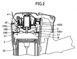
- FIG. 2 A comparative arrangement is shown in Fig. 2, in which a widthwise center (line C) of fan blades in the axial direction of the rotation shaft is offset toward the cylinder head 11 from the connecting portion 10B1.
- line C a widthwise center of fan blades in the axial direction of the rotation shaft
- the present invention is not limited to the nail gun but is available for any kind of power tools in which a combustion chamber and a piston are provided, and as long as expansion of gas as a result of combustion of air-fuel mixture in the combustion chamber causes reciprocal motion of the piston.
Landscapes
- Engineering & Computer Science (AREA)
- Chemical & Material Sciences (AREA)
- Combustion & Propulsion (AREA)
- Mechanical Engineering (AREA)
- Portable Nailing Machines And Staplers (AREA)
Abstract
Description
- The present invention relates to a combustion-type power tool, and more particularly, to such power tool capable of driving a fastener such as a nail, an anchor, and a staple into a workpiece.
- In a conventional combustion-type power tool such as a nail gun, a mixture of air and gaseous fuel injected into a combustion chamber is ignited by a spark at an ignition plug to cause gas expansion in the combustion chamber, which in turn causes a linear momentum of a piston. By the movement of the piston, a nail is driven into a workpiece. Such conventional combustion-type nail gun is described in U.S.Patent No. 5,197,646 and Japanese Patent Publication No. H03-25307.
- However, there has been a demand of cooling a component such as a cylinder.
- The present inventors contemplated optimum position of a fan within a combustion chamber so as to provide an optimum air flow and air flow amount for cooling the component such as a cylinder.
- It is therefore an object of the present invention to provide a combustion-type power tool capable of providing a sufficient amount of fan flow for efficiently cooling a component such as a cylinder by setting a fan at an optimum position.
- This and other object of the present invention will be attained by a combustion-type power tool including a housing, a cylinder head, a cylinder, a piston, a push lever, a combustion chamber frame, a driver blade, an ignition plug, and a fan.
- The housing has one end and another end and is formed with an exhaust port The cylinder head is disposed at the one end. The cylinder is disposed in and fixed to the housing. The cylinder defines an axial direction. The piston is slidably disposed in the cylinder and reciprocally movable in the axial direction. The push lever is disposed at the another end of the housing and movable in the axial direction upon pressing against a workpiece. The combustion chamber frame is disposed in the housing and movable in the axial direction. The combustion chamber frame includes a base section and a head section. The base section is associated with the push lever, and has one end which is a remote side from the push lever. The head section is fixed to the one end of the base section and abuttable on the cylinder head. The head section includes a disc like connecting portion having a radially outer edge connected to the one end of the base section and having an radially inner edge, and a sleeve like abutment portion extending in the axial direction from the radially inner edge toward the cylinder head and abuttable on the cylinder head to provide a combustion chamber in cooperation with the cylinder head and the piston.
- The driver blade extends in the axial direction from the piston toward the another end of the housing. The ignition plug is exposed to the combustion chamber for igniting a mixture of air and the combustible gas in the combustion chamber. The fan is rotatably disposed in the combustion chamber for agitating and mixing the air with the combustible gas. The fan includes fan blades which define a widthwise center line in the axial direction. The widthwise center line is offset from the connecting portion and toward the piston in a non-operational phase.
- In another aspect of the invention, there is provided a combustion-type power tool including a housing, a cylinder head, a combustion chamber, and a fan. The housing has one end and another end. The housing defines one direction which goes from the one end to the another end. The cylinder head is disposed at the one end. The combustion chamber frame is disposed in the housing and reciprocally movable in the one direction between a closed position in contact with the cylinder head and an open position out of contact from the cylinder head. The combustion chamber frame includes a base section and a head section. The head section is fixed to the base section and abuttable on the cylinder head. The head section includes a disc like connecting portion and a sleeve like abutment portion. The connection portion has a radially outer edge connected to the base section and has an radially inner edge. The abutment portion extends in the one direction from the radially inner edge toward the cylinder head and abuttable on the cylinder head to provide a combustion chamber in cooperation with the cylinder head. The fan is rotatably disposed in the combustion chamber. The fan includes fan blades which define a widthwise center line in the one direction. The widthwise center line is offset from the connecting portion in the one direction and toward the another end of the housing in the open position.
- In the drawings;
- Fig. 1 is a vertical cross-sectional side view showing a combustion-type nail gun embodying a combustion-type power tool according to an embodiment of the present invention, the nail gun being in an initial phase prior to nail driving operation; and
- Fig. 2 is a partial cross-sectional side view showing a comparative combustion-type nail gun where a distance between a fan and a cylinder head is shorter than that in the embodiment of the present invention.
- A combustion-type power tool according to one embodiment of the present invention will be described with reference to Fig. 1. The embodiment pertains to a combustion-type nail gun. Throughout the specification, the term "upper" and "lower" are used assuming that the combustion-type nail gun is oriented in a vertical direction. The combustion-type nail gun 1 has a
housing 2 constituting an outer frame. The housing is formed with anexhaust port 2a. Ahead cover 3 formed with anintake port 3a is mounted on the top of thehousing 2. Ahandle 4 is attached to thehousing 2 and extends from a side of thehousing 2. - The
handle 4 has atrigger switch 5 and accommodates therein a battery (not shown). The battery is detachably disposed in thehandle 4. Acanister housing 29 is provided in thehousing 2 at a position immediately beside thehandle 4. Thegas canister 30 is detachably disposed in thecanister housing 29. Thegas canister 30 includes aninjection rod 30A to be connected to a gascanister connecting portion 25A provided in a cylinder head 11 (described later). Amagazine 6 for containing therein nails (not shown) is provided at a lower side of thehandle 4 of thehousing 2. - A
nose 7 extends from an end of thehousing 2, the end being opposite to thehead cover 3. Thenose 7 is formed integrally with a cylinder 20 (described later) and has a tip end in confrontation with aworkpiece 28. Thenose 7 is adapted for guiding sliding movement of adrive blade 23A (described later) and the nail. Apush lever 9 is movably provided and has a lower portion slidable with respect to alower end portion 7A of thenose 7. Thepush lever 9 has a tip end adapted to be pressed against theworpiece 28, and has an upper end portion associated with anarm member 8 fixed to abase section 10A of acombustion chamber frame 10 which will be described later. - A
compression coil spring 22 is interposed between thearm member 8 and thecylinder 20 for normally urging thepush lever 9 in a protruding direction away from thehead cover 3. When thehousing 2 is pressed toward theworkpiece 28 while thepush lever 9 is in abutment with theworkpiece 28 against a biasing force of thecompression coil spring 22, an upper portion of thepush lever 9 is retractable into thehousing 2. - A
cylinder head 11 is secured to the top of thehousing 2 for closing the open top end of thehousing 2. Thecylinder head 11 supports amotor 18 at a position opposite to a combustion chamber 26 described later. Further, anignition plug 12 is also supported to thecylinder head 11 at a position adjacent to themotor 18. The ignition plug 12 has an ignition spot exposed to the combustion chamber 26. The ignition plug 12 is ignitable upon manipulation to thetrigger switch 5 and upon movement of thecombustion chamber frame 10 to its predetermined position because of the pressing of thepush lever 9 against theworkpiece 28. Themotor 18 has arotation shaft 18A, and afan 19 positioned in the combustion chamber 26 is fixed to a tip end of therotation shaft 18A. - The
cylinder head 11 has a handle side in which is formed afuel injection passage 25 which allows a combustible gas to pass therethrough. One end of thefuel injection passage 25 serves as an injection port that opens at the lower surface of thecylinder head 11. Another end of thefuel injection passage 25 is engaged with the gascanister connecting portion 25A in communication with theinjection rod 30A. - The
combustion chamber frame 10 is provided in thehousing 2 and is movable in the lengthwise direction of thehousing 2. Thecombustion chamber frame 10 includes thebase section 10A and ahead section 10B extending from thebase section 10A at a position opposite to thepush lever 9. Thehead section 10B includes a radial connecting portion 10B1 having an outer end connected to thebase section 10A and extending radially inwardly toward therotation shaft 18A, and an abutment portion 10B2 extending in parallel with therotation shaft 18A from a radially inner end of the connecting portion 10B1. The abutment portion 10B2 is movable to abut on and away from thecylinder head 11. Thecombustion chamber frame 10 is moved interlockingly in accordance with the movement of thepush lever 9, since thearm member 8 is fixed to thebase section 10A. - A head switch (not shown) is provided in the
housing 2 for detecting an uppermost stroke end position of thecombustion chamber frame 10 when the nail gun 1 is pressed against theworkpiece 28. The head switch can be turned ON when thepush lever 9 is elevated to a predetermined position for starting rotation of themotor 18. - The
cylinder 20 is fixed to thehousing 2. Thecombustion chamber frame 10 has an inner surface in sliding contact with thecylinder 20. Thus, thecylinder 20 guides movement of thecombustion chamber frame 10. Thecylinder 20 has an axially intermediate portion formed with anexhaust hole 21. An exhaust-gas check valve (not shown) is provided to selectively close theexhaust hole 21. - A
piston 23 is slidably and reciprocally provided in thecylinder 20. Thepiston 23 divides an inner space of thecylinder 20 into an upper space above thepiston 23 and a lower space below thepiston 23. Thedriver blade 23A extends downwards from a side of thepiston 23, the side being at the cylinder space below thepiston 23, to thenose 7. Thedriver blade 23A is positioned coaxially with the nail setting position in thenose 7, so that thedriver blade 23A can strike against the nail during movement of thepiston 23 toward its bottom dead center. Further, abumper 24 is provided on the bottom of thecylinder 20. Thebumper 24 is made from a resilient material. When thepiston 23 moves to its bottom dead center, thepiston 23 abuts on thebumper 24 and stops. In this case, thebumper 24 absorbs a surplus energy of thepiston 23. - When the upper end of the abutment portion 10B2 of the
combustion chamber frame 10 abuts on thecylinder head 11, thecylinder head 11, thecombustion chamber frame 10, and the upper cylinder space above thepiston 23 define in combustion the combustion chamber 26. When the abutment portion 10B2 is separated from thecylinder head 11, a first flow passage 31 in communication with an atmosphere is provided between thecylinder head 11 and the abutment portion 10B2, and asecond flow passage 32 in communication with the first flow passage 31 is provided between thebase section 10A of thecombustion chamber frame 10 and the upper end portion of thecylinder 20. Theseflow passages 31, 32 allow a combustion gas and a fresh air to pass along the outer peripheral surface of thecylinder 20 for discharging these gas through theexhaust port 2a of thehousing 2. Further, the above-describedintake port 3a is formed for supplying a fresh air into the combustion chamber 26, and theexhaust hole 21 is adapted for discharging combustion gas generated in the combustion chamber 26. - During non-operational state of the
fan 19, a widthwise center line (line A) of the fan blade in an axial direction of therotation shaft 18A is offset from the connecting portion 10B1 toward thepush lever 9. In other words, the widthwise center line A is closer to thepush lever 9 than the connecting portion 10B1 to thepush lever 9. Further, the fan blade has one end positioned close to thecylinder head 11. The one end of the fan blade (line B) is positioned coincident with the connecting portion 10B1, or the line B is offset from the connecting portion 1OB1 toward thecylinder head 11 in the axial direction of therotation shaft 18A. That is, the line B is closer to thecylinder head 11 than the connecting portion 1OB1 to thecylinder head 11 in the non-operational phase of thefan 19. - Rotation of the
fan 19 performs the following three functions. First, thefan 19 stirs and mixes the air with the combustible gas as long as thecombustion chamber frame 10 remains in abutment with thecylinder head 11. Second, after the mixed gas has been ignited, thefan 19 causes turbulent combustion of the air-fuel mixture, thus promoting the combustion of the air-fuel mixture in the combustion chamber 26. Third, thefan 19 performs scavenging such that the exhaust gas in the combustion chamber 26 can be scavenged therefrom and also performs cooling to thecombustion chamber frame 10 and thecylinder 20 when thecombustion chamber frame 10 moves away from thecylinder head 11 and when the first andsecond flow passages 31, 32 are provided. - Next, operation of the combustion-type nail gun 1 will be described. In the non-operational state of the combustion-type nail gun 1, the
push lever 9 is biased away from thecylinder head 11 as shown in Fig. 1 by the biasing force of thecompression coil spring 22, so that thepush lever 9 protrudes from the lower end of thenose 7. Thus, the uppermost end portion of the abutment portion 10B2 is spaced away from thecylinder head 11 because thearm member 8 connects thecombustion chamber frame 10 to thepush lever 9. Further, a part of thebase section 10A which part defines the combustion chamber 26 is also spaced away from the top portion of thecylinder 20. Hence, the first andsecond flow passages 31 and 32 are provided. In this condition, thepiston 23 stays at its top dead center in thecylinder 20. - With this state, if the
push lever 9 is pushed onto theworkpiece 28 while holding thehandle 4 by a user, thepush lever 9 is moved toward thecylinder head 11 against the biasing force of thecompression coil spring 22. At the same time, thecombustion chamber frame 10 which is associated with thepush lever 9 through thearm member 8 is also moved toward thecylinder head 11, closing the above-describedflow passages 31 and 32. Thus, the sealed combustion chamber 26 is provided. - In accordance with the movement of the
push lever 9, the liquidized gas in thegas canister 30 is injected into the combustion chamber 26 through the gascanister connecting portion 25A and through thefuel injection passage 25. - Further, in accordance with the movement of the
push lever 9, thecombustion chamber frame 10 reaches its uppermost stroke end whereupon the head switch is turned ON to energize themotor 18 for starting rotation of thefan 19. Rotation of thefan 19 stirs and mixes the combustible gas with air in the combustion chamber 26. - In this state, when the
trigger switch 5 provided at thehandle 4 is turned ON, spark is generated at theignition plug 12 to ignite the combustible gas. The combusted and expanded gas pushes thepiston 23 to its bottom dead center. Therefore, a nail in thenose 7 is driven into theworkpiece 28 by thedriver blade 23A until thepiston 23 abuts on thebumper 24. - After the nail driving, the
piston 23 strikes against thebumper 24, the cylinder space above thepiston 23 becomes communicated with theexhaust hole 21. Thus, the high pressure and high temperature combustion gas is discharged out of thecylinder 20 through theexhaust hole 21 of thecylinder 20 and through the check valve (not shown) provided at theexhaust hole 21 to the atmosphere to lower the pressure in the combustion chamber 26. When the inner space of thecylinder 20 and the combustion chamber 26 becomes the atmospheric pressure, the check valve is closed. - Combustion gas still remaining in the
cylinder 20 and the combustion chamber 26 has a high temperature at a phase immediately after the combustion. However, the high temperature can be absorbed into the walls of thecylinder 20 and thecombustion chamber frame 10. The absorbed heat is diffused to the atmosphere from thecylinder 20 and thecombustion chamber frame 10. - Absorption of the heat into the
cylinder 20 etc. causes rapid cooling to the combustion gas. Thus, the pressure in the sealed space in thecylinder 20 above thepiston 23 further drops to less than the atmospheric pressure (creating a so-called "thermal vacuum"). Accordingly, thepiston 23 can be moved back to the initial top dead center position. - Then, the
trigger switch 5 is turned OFF, and the user lifts the combustion-type nail gun 1 from theworkpiece 28 for separating thepush lever 9 from theworkpiece 28. As a result, thepush lever 9 and thecombustion chamber frame 10 move away from thecylinder head 11 because of the biasing force of thecompression coil spring 22 to restore a state shown in Fig. 1. Thus, the first andsecond flow passages 31 and 32 are provided. In this case, thefan 19 is configured to keep rotating for a predetermined period of time, for example 7 seconds or less after the detection of the predetermined position of thecombustion chamber frame 10 by the head switch in spite of OFF state of thetrigger switch 5. Thus, in the state shown in Fig. 1, fresh air is introduced into the combustion chamber 26 through theintake port 3a formed at thehead cover 3 as indicated by an arrow "a1" by the rotation of thefan 19. - The fresh air then flows through the first flow passage 31 as indicated by an arrow "a2". Here, sufficient fan velocity pressure is required in order to provide a smooth air flow, since cross-sectional areas of the
second flow passage 32 and theexhaust port 2a those positioned downstream of the air flow "a2" are small. In order to provide high fan velocity pressure, thefan 19 and its ambient arrangement should allow the air flow immediately discharged from thefan 19 to be directed radially outwardly of thefan 19 as indicated by an arrow "a3". In the present embodiment, since the widthwise center portion (line A) of the fan blade is offset toward thepush lever 9 from the connecting portion 10B1, the air flow immediately discharged from thefan 19 is not interrupted by the connecting portion 10B1 and the abutment portion 10B2. - Further, since the one end of the fan blade (line B) is positioned coincident with the connecting portion 10B1, or the line B is offset from the connecting portion 10B1 toward the
cylinder head 11 in the axial direction of therotation shaft 18A, the air flow discharged from thefan 19 will not be self-circulated within the combustion chamber 26. Accordingly, air can smoothly flow toward thesecond flow passage 32. As a result, flow rate passing through the first andsecond flow passages 31,32 can be increased. Then, the air passes through thesecond flow passage 32 and is discharged to the atmosphere through theexhaust port 2a as indicated by an arrow "a4". Consequently, residual combustion gas in the combustion chamber 26 can be expelled out of theexhaust port 2a. Thus, the combustion chamber 26 is scavenged. - The air flow can also cool the walls of the
cylinder 20 and thecombustion chamber frame 10 having high temperature. Since high fan flow rate can be provided in the embodiment, sufficient cooling efficiency to the cylinders etc. can be provided, to enhance operability to the tool particularly for the continuous repeated nail driving operation. In other words, electrical power supplying period to themotor 18 for rotating thefan 19 can be reduced. For example, in a conventional nail gun, a fan is configured to keep rotating for not less than 8 seconds after the detection of the predetermined position of thecombustion chamber frame 10 by the head switch in order to sufficiently cool the components. On the contrary, in the present embodiment, the power supplying period is less than 8 seconds, such as 7 seconds or less, yet performing sufficient cooling function. This implies that the battery can provide an increased numbers of nail driving times, i.e., prolonged service life of the battery results. Then, the rotation of thefan 19 is stopped to restore an initial stationary state. Thereafter, subsequent nail driving operation can be performed by repeating the above described operation process. - A comparative arrangement is shown in Fig. 2, in which a widthwise center (line C) of fan blades in the axial direction of the rotation shaft is offset toward the
cylinder head 11 from the connecting portion 10B1. With this structure, air discharged from thefan 19 is impinged against the abutment portion 10B2 and the connecting portion 10B1 as indicated by an arrow b1 to disturb air flow. Consequently, sufficient flow rate is not obtainable to increase the period for cooling thecylinder 20 etc, to lower operability of the tool particularly for the repeated nail driving operation. - While the invention has been described in detail and with reference to specific embodiments thereof, it would be apparent to those skilled in the art that various changes and modification may be made therein without departing from the scope of the invention. For example, the present invention is not limited to the nail gun but is available for any kind of power tools in which a combustion chamber and a piston are provided, and as long as expansion of gas as a result of combustion of air-fuel mixture in the combustion chamber causes reciprocal motion of the piston.
Claims (8)
- A combustion-type power tool comprising:a housing having one end and another end;a cylinder head disposed at the one end;a cylinder disposed in and fixed to the housing, the cylinder defining an axial direction;a piston slidably disposed in the cylinder and reciprocally movable in the axial direction;a push lever disposed at the another end of the housing and movable in the axial direction upon pressing against a workpiece;a combustion chamber frame disposed in the housing and movable in the axial direction, the combustion chamber frame comprising:a base section associated with the push lever, and having one end which is a remote side from the push lever; and,a head section fixed to the one end of the base section and abuttable on the cylinder head, the head section including a disc like connecting portion having a radially outer edge connected to the one end of the base section and having an radially inner edge, and a sleeve like abutment portion extending in the axial direction from the radially inner edge toward the cylinder head and abuttable on the cylinder head to provide a combustion chamber in cooperation with the cylinder head and the piston;a driver blade extending in the axial direction from the piston toward the another end of the housing;an ignition plug exposed to the combustion chamber for igniting a mixture of air and the combustible gas in the combustion chamber; anda fan rotatably disposed in the combustion chamber for agitating and mixing the air with the combustible gas, the fan including fan blades which define a widthwise center line in the axial direction, the widthwise center line being offset from the connecting portion in the axial direction and toward the piston in a non-operational phase.
- The combustion-type power tool as claimed in claim 1,
wherein the housing is formed with an exhaust port; and
wherein the combustion chamber frame is movable away from the cylinder head to provide a first flow passage in communication with an atmosphere and between the abutment portion and the cylinder head, and provide a second flow passage in communication with the first flow passage and the exhaust port and between the base section and the cylinder. - The combustion-type power tool as claimed in claim 1, wherein the fan blades each has a widthwise edge at a side of the cylinder head in the axial direction, the widthwise edge is positioned coincident with the connecting portion in the non-operational phase.
- The combustion-type power tool as claimed in claim 1, wherein the fan blades each has a widthwise edge at a side of the cylinder head in the axial direction, the widthwise edge is positioned offset from the connecting portion in the axial direction and toward the cylinder head in the non-operational phase.
- The combustion-type power tool as claimed in claim 1, further comprising:a head switch disposed in the housing for detecting a predetermined position of the combustion chamber frame relative to the housing when the combustion chamber frame is moved toward the cylinder head as a result of pressing of the push lever against the workpiece; anda motor disposed at the cylinder head and having a motor shaft extending into the combustion chamber frame, the fan being fixed to the motor shaft, an electric power being supplied to the motor to rotate upon detection of the predetermined position by the head switch for starting and continuing rotation of the fan for a period of not more than 7 seconds.
- A combustion-type power tool comprising:a housing having one end and another end, the housing defining one direction which goes from the one end to the another end;a cylinder head disposed at the one end;a combustion chamber frame disposed in the housing and reciprocally movable in the one direction between a closed position in contact with the cylinder head and an open position out of contact from the cylinder head, the combustion chamber frame comprising:a base section; and,a head section fixed to the base section and abuttable on the cylinder head, the head section including a disc like connecting portion having a radially outer edge connected to the base section and having an radially inner edge, and a sleeve like abutment portion extending in the one direction from the radially inner edge toward the cylinder head and abuttable on the cylinder head to provide a combustion chamber in cooperation with the cylinder head;a fan rotatably disposed in the combustion chamber, the fan including fan blades which define a widthwise center line in the one direction, the widthwise center line being offset from the connecting portion in the one direction and toward the another end of the housing in the open position.
- The combustion-type power tool as claimed in claim 6, wherein the fan blades each has a widthwise edge at a side of the cylinder head in the one direction, the widthwise edge is positioned coincident with the connecting portion in the open position.
- The combustion-type power tool as claimed in claim 6, wherein the fan blades each has a widthwise edge at a side of the cylinder head in the one direction, the widthwise edge is positioned offset from the connecting portion in the one direction and toward the cylinder head in the open position.
Applications Claiming Priority (1)
| Application Number | Priority Date | Filing Date | Title |
|---|---|---|---|
| JP2004243987A JP4297011B2 (en) | 2004-08-24 | 2004-08-24 | Combustion power tool |
Publications (2)
| Publication Number | Publication Date |
|---|---|
| EP1629948A1 true EP1629948A1 (en) | 2006-03-01 |
| EP1629948B1 EP1629948B1 (en) | 2012-10-10 |
Family
ID=35406286
Family Applications (1)
| Application Number | Title | Priority Date | Filing Date |
|---|---|---|---|
| EP05255207A Expired - Lifetime EP1629948B1 (en) | 2004-08-24 | 2005-08-24 | Combustion-type power tool having cooling arrangement |
Country Status (3)
| Country | Link |
|---|---|
| US (2) | US7237515B2 (en) |
| EP (1) | EP1629948B1 (en) |
| JP (1) | JP4297011B2 (en) |
Cited By (1)
| Publication number | Priority date | Publication date | Assignee | Title |
|---|---|---|---|---|
| CN105500290A (en) * | 2016-02-14 | 2016-04-20 | 重庆双伟机械有限公司 | Gas combustion type impact tool |
Families Citing this family (9)
| Publication number | Priority date | Publication date | Assignee | Title |
|---|---|---|---|---|
| JP4534667B2 (en) * | 2004-08-24 | 2010-09-01 | 日立工機株式会社 | Combustion power tool |
| DE102004047279A1 (en) * | 2004-09-29 | 2006-04-06 | Hilti Ag | Internal combustion setting device |
| US7314025B2 (en) * | 2005-07-15 | 2008-01-01 | Illinois Tool Works Inc. | Combustion powered fastener-driving tool with interconnected chambers |
| DE102006000162A1 (en) * | 2006-04-06 | 2007-10-11 | Hilti Ag | Electric hand tool machine with internal cooling fan |
| JP5070876B2 (en) * | 2007-02-15 | 2012-11-14 | マックス株式会社 | Gas fired driving tool |
| TW201013055A (en) * | 2008-09-26 | 2010-04-01 | Basso Ind Corp | Motor fan device with shock-absorbing function |
| US9662777B2 (en) | 2013-08-22 | 2017-05-30 | Techtronic Power Tools Technology Limited | Pneumatic fastener driver |
| US10843318B2 (en) * | 2015-04-30 | 2020-11-24 | Koki Holdings Co., Ltd. | Fastener driving machine |
| EP4360810A1 (en) | 2022-10-25 | 2024-05-01 | Milwaukee Electric Tool Corporation | Powered fastener driver |
Citations (5)
| Publication number | Priority date | Publication date | Assignee | Title |
|---|---|---|---|---|
| JPH0325307B2 (en) | 1981-01-22 | 1991-04-05 | Signode Corp | |
| US5197646A (en) | 1992-03-09 | 1993-03-30 | Illinois Tool Works Inc. | Combustion-powered tool assembly |
| EP0857546A1 (en) * | 1997-02-07 | 1998-08-12 | Illinois Tool Works Inc. | Combustion powered tool |
| US6145724A (en) * | 1997-10-31 | 2000-11-14 | Illinois Tool Works, Inc. | Combustion powered tool with combustion chamber delay |
| EP1391270A1 (en) * | 2002-08-09 | 2004-02-25 | Hitachi Koki Co., Ltd. | Combustion-powered nail gun |
Family Cites Families (2)
| Publication number | Priority date | Publication date | Assignee | Title |
|---|---|---|---|---|
| JP4135069B2 (en) * | 2002-08-09 | 2008-08-20 | 日立工機株式会社 | Combustion type driving tool |
| US6796476B2 (en) * | 2002-09-11 | 2004-09-28 | Illinois Tool Works Inc. | Power control system for a framing tool |
-
2004
- 2004-08-24 JP JP2004243987A patent/JP4297011B2/en not_active Expired - Fee Related
-
2005
- 2005-08-23 US US11/208,593 patent/US7237515B2/en not_active Expired - Lifetime
- 2005-08-24 EP EP05255207A patent/EP1629948B1/en not_active Expired - Lifetime
-
2007
- 2007-06-19 US US11/764,953 patent/US7387092B2/en not_active Expired - Lifetime
Patent Citations (5)
| Publication number | Priority date | Publication date | Assignee | Title |
|---|---|---|---|---|
| JPH0325307B2 (en) | 1981-01-22 | 1991-04-05 | Signode Corp | |
| US5197646A (en) | 1992-03-09 | 1993-03-30 | Illinois Tool Works Inc. | Combustion-powered tool assembly |
| EP0857546A1 (en) * | 1997-02-07 | 1998-08-12 | Illinois Tool Works Inc. | Combustion powered tool |
| US6145724A (en) * | 1997-10-31 | 2000-11-14 | Illinois Tool Works, Inc. | Combustion powered tool with combustion chamber delay |
| EP1391270A1 (en) * | 2002-08-09 | 2004-02-25 | Hitachi Koki Co., Ltd. | Combustion-powered nail gun |
Cited By (1)
| Publication number | Priority date | Publication date | Assignee | Title |
|---|---|---|---|---|
| CN105500290A (en) * | 2016-02-14 | 2016-04-20 | 重庆双伟机械有限公司 | Gas combustion type impact tool |
Also Published As
| Publication number | Publication date |
|---|---|
| US20060042573A1 (en) | 2006-03-02 |
| US20070240651A1 (en) | 2007-10-18 |
| US7237515B2 (en) | 2007-07-03 |
| US7387092B2 (en) | 2008-06-17 |
| JP2006061992A (en) | 2006-03-09 |
| JP4297011B2 (en) | 2009-07-15 |
| EP1629948B1 (en) | 2012-10-10 |
Similar Documents
| Publication | Publication Date | Title |
|---|---|---|
| US7387092B2 (en) | Combustion-type power tool having cooling arrangement | |
| AU2007292056B2 (en) | Combustion-type power tool | |
| CA2226449C (en) | Combustion powered tool with dual fans | |
| US7225768B2 (en) | Combustion type power tool having buffer piece | |
| US20070138231A1 (en) | Combustion type power tool having segmental connection unit | |
| EP1693159B1 (en) | Combustion-type power tool | |
| US20060249107A1 (en) | Combustion type power tool having motor suspension arrangement | |
| US7484481B2 (en) | Combustion-type power tool having switch protection arrangement | |
| US7063053B2 (en) | Combustion type power tool having fin for effectively cooling cylinder | |
| US7743955B2 (en) | Combustion type power tool having fan | |
| US20060042574A1 (en) | Combustion-type power tool providing specific spark energy | |
| US7305940B2 (en) | Combustion-type power tool having ignition proof arrangement | |
| US7131404B2 (en) | Combustion-type power tool having gas canister cooling arrangement | |
| US7293541B2 (en) | Combustion-type power tool having ignition proof arrangement |
Legal Events
| Date | Code | Title | Description |
|---|---|---|---|
| PUAI | Public reference made under article 153(3) epc to a published international application that has entered the european phase |
Free format text: ORIGINAL CODE: 0009012 |
|
| AK | Designated contracting states |
Kind code of ref document: A1 Designated state(s): AT BE BG CH CY CZ DE DK EE ES FI FR GB GR HU IE IS IT LI LT LU LV MC NL PL PT RO SE SI SK TR |
|
| AX | Request for extension of the european patent |
Extension state: AL BA HR MK YU |
|
| 17P | Request for examination filed |
Effective date: 20060823 |
|
| AKX | Designation fees paid |
Designated state(s): DE FR GB |
|
| 17Q | First examination report despatched |
Effective date: 20061128 |
|
| GRAP | Despatch of communication of intention to grant a patent |
Free format text: ORIGINAL CODE: EPIDOSNIGR1 |
|
| GRAS | Grant fee paid |
Free format text: ORIGINAL CODE: EPIDOSNIGR3 |
|
| GRAA | (expected) grant |
Free format text: ORIGINAL CODE: 0009210 |
|
| AK | Designated contracting states |
Kind code of ref document: B1 Designated state(s): DE FR GB |
|
| REG | Reference to a national code |
Ref country code: GB Ref legal event code: FG4D Ref country code: DE Ref legal event code: R081 Ref document number: 602005036469 Country of ref document: DE Owner name: KOKI HOLDINGS CO., LTD., JP Free format text: FORMER OWNER: HITACHI KOKI CO., LTD., TOKIO/TOKYO, JP |
|
| REG | Reference to a national code |
Ref country code: DE Ref legal event code: R096 Ref document number: 602005036469 Country of ref document: DE Effective date: 20121206 |
|
| PLBE | No opposition filed within time limit |
Free format text: ORIGINAL CODE: 0009261 |
|
| STAA | Information on the status of an ep patent application or granted ep patent |
Free format text: STATUS: NO OPPOSITION FILED WITHIN TIME LIMIT |
|
| 26N | No opposition filed |
Effective date: 20130711 |
|
| REG | Reference to a national code |
Ref country code: DE Ref legal event code: R097 Ref document number: 602005036469 Country of ref document: DE Effective date: 20130711 |
|
| REG | Reference to a national code |
Ref country code: FR Ref legal event code: PLFP Year of fee payment: 12 |
|
| REG | Reference to a national code |
Ref country code: FR Ref legal event code: PLFP Year of fee payment: 13 |
|
| REG | Reference to a national code |
Ref country code: DE Ref legal event code: R082 Ref document number: 602005036469 Country of ref document: DE Representative=s name: GULDE & PARTNER PATENT- UND RECHTSANWALTSKANZL, DE Ref country code: DE Ref legal event code: R081 Ref document number: 602005036469 Country of ref document: DE Owner name: KOKI HOLDINGS CO., LTD., JP Free format text: FORMER OWNER: HITACHI KOKI CO., LTD., TOKIO/TOKYO, JP |
|
| REG | Reference to a national code |
Ref country code: FR Ref legal event code: PLFP Year of fee payment: 14 |
|
| REG | Reference to a national code |
Ref country code: DE Ref legal event code: R084 Ref document number: 602005036469 Country of ref document: DE |
|
| REG | Reference to a national code |
Ref country code: GB Ref legal event code: 746 Effective date: 20181031 |
|
| PGFP | Annual fee paid to national office [announced via postgrant information from national office to epo] |
Ref country code: FR Payment date: 20210819 Year of fee payment: 17 |
|
| PGFP | Annual fee paid to national office [announced via postgrant information from national office to epo] |
Ref country code: DE Payment date: 20210819 Year of fee payment: 17 Ref country code: GB Payment date: 20210824 Year of fee payment: 17 |
|
| REG | Reference to a national code |
Ref country code: DE Ref legal event code: R119 Ref document number: 602005036469 Country of ref document: DE |
|
| GBPC | Gb: european patent ceased through non-payment of renewal fee |
Effective date: 20220824 |
|
| PG25 | Lapsed in a contracting state [announced via postgrant information from national office to epo] |
Ref country code: FR Free format text: LAPSE BECAUSE OF NON-PAYMENT OF DUE FEES Effective date: 20220831 Ref country code: DE Free format text: LAPSE BECAUSE OF NON-PAYMENT OF DUE FEES Effective date: 20230301 |
|
| PG25 | Lapsed in a contracting state [announced via postgrant information from national office to epo] |
Ref country code: GB Free format text: LAPSE BECAUSE OF NON-PAYMENT OF DUE FEES Effective date: 20220824 |