EP1628451A2 - Method and apparatus for estimating sampling frequency offset and for compensating said sampling frequency offset in a digital receiver - Google Patents
Method and apparatus for estimating sampling frequency offset and for compensating said sampling frequency offset in a digital receiver Download PDFInfo
- Publication number
- EP1628451A2 EP1628451A2 EP05291742A EP05291742A EP1628451A2 EP 1628451 A2 EP1628451 A2 EP 1628451A2 EP 05291742 A EP05291742 A EP 05291742A EP 05291742 A EP05291742 A EP 05291742A EP 1628451 A2 EP1628451 A2 EP 1628451A2
- Authority
- EP
- European Patent Office
- Prior art keywords
- sfo
- value
- phase
- estimated phase
- estimated
- Prior art date
- Legal status (The legal status is an assumption and is not a legal conclusion. Google has not performed a legal analysis and makes no representation as to the accuracy of the status listed.)
- Withdrawn
Links
- 238000005070 sampling Methods 0.000 title claims abstract description 41
- 238000000034 method Methods 0.000 title claims abstract description 40
- 230000005540 biological transmission Effects 0.000 description 5
- 230000008901 benefit Effects 0.000 description 4
- 238000010586 diagram Methods 0.000 description 4
- 230000008569 process Effects 0.000 description 4
- 230000008859 change Effects 0.000 description 3
- 238000005562 fading Methods 0.000 description 3
- 230000001788 irregular Effects 0.000 description 2
- 238000012986 modification Methods 0.000 description 2
- 230000004048 modification Effects 0.000 description 2
- 230000009467 reduction Effects 0.000 description 2
- 239000000654 additive Substances 0.000 description 1
- 230000000996 additive effect Effects 0.000 description 1
- 238000004364 calculation method Methods 0.000 description 1
- 230000000694 effects Effects 0.000 description 1
- 238000000605 extraction Methods 0.000 description 1
Images





Classifications
-
- H—ELECTRICITY
- H04—ELECTRIC COMMUNICATION TECHNIQUE
- H04N—PICTORIAL COMMUNICATION, e.g. TELEVISION
- H04N7/00—Television systems
- H04N7/12—Systems in which the television signal is transmitted via one channel or a plurality of parallel channels, the bandwidth of each channel being less than the bandwidth of the television signal
-
- H—ELECTRICITY
- H04—ELECTRIC COMMUNICATION TECHNIQUE
- H04L—TRANSMISSION OF DIGITAL INFORMATION, e.g. TELEGRAPHIC COMMUNICATION
- H04L27/00—Modulated-carrier systems
- H04L27/26—Systems using multi-frequency codes
- H04L27/2601—Multicarrier modulation systems
- H04L27/2647—Arrangements specific to the receiver only
- H04L27/2655—Synchronisation arrangements
- H04L27/2668—Details of algorithms
- H04L27/2681—Details of algorithms characterised by constraints
- H04L27/2688—Resistance to perturbation, e.g. noise, interference or fading
-
- H—ELECTRICITY
- H04—ELECTRIC COMMUNICATION TECHNIQUE
- H04L—TRANSMISSION OF DIGITAL INFORMATION, e.g. TELEGRAPHIC COMMUNICATION
- H04L27/00—Modulated-carrier systems
- H04L27/26—Systems using multi-frequency codes
- H04L27/2601—Multicarrier modulation systems
- H04L27/2647—Arrangements specific to the receiver only
- H04L27/2655—Synchronisation arrangements
- H04L27/2662—Symbol synchronisation
Definitions
- the present invention relates to a digital receiver, and more particularly, to a method and apparatus for estimating an SFO (Sampling Frequency Offset) applicable to the digital receiver, and an apparatus for compensating for a sampling frequency using the estimated SFO.
- SFO Samling Frequency Offset
- a DVB-T (Digital Video Broadcasting - Terrestrial) system acting as the European transmission standard for a terrestrial digital TV has generally selected an OFDM (Orthogonal Frequency Division Multiplexing) transmission scheme. It is well known in the art that the OFDM transmission scheme has very strong resistance to channel distortion caused by multiple paths (also called a multi-path) in a wireless broadband broadcast system.
- OFDM Orthogonal Frequency Division Multiplexing
- the OFDM transmission scheme has very weak resistance to synchronization. Therefore, if accurate synchronization is not established between a transmitter and a receiver, distortion of a reception signal occurs.
- many developers have conducted intensive research into the improved OFDM transmission scheme.
- an ISI inter Symbol Interference
- a constellation rotation may occur in a reception signal, such that the receiver cannot demodulate the reception signal.
- FIG. 1 shows general CP positions. As shown in FIG. 1, 45 pilots are employed during a 2k mode, and 177 pilots are employed during an 8k mode.
- a total of 1705 data subcarriers are present in one OFDM symbol interval.
- a pilot is located at each of subcarrier positions, for example, 0-th, 48-th, and 54-th subcarrier positions, etc.
- the pilot is positioned at the same subcarrier positions as the above subcarrier positions in the next OFDM symbol, such that the pilot will be referred to as a Continual Pilot (CP).
- CP Continual Pilot
- FIG. 2 A method for calculating the SFO using the above-mentioned CP information shown in FIG. 1 is shown in FIG. 2.
- FIG. 2 is a block diagram illustrating a conventional SFO estimation system.
- the SFO estimation system receives a single signal Z l,k .
- the Z l,k signal is indicative of a k-th subcarrier in a first OFDM symbol.
- the Z l,k signal is indicative of one pilot from among a plurality of pilots (i.e., 0-th, 48-th, and 53-th symbols, etc.) in the first OFDM symbol.
- the Z l,k signal is converted into another signal of Z l- 1, k via a delay 10.
- the Z l -1, k signal is converted into a conjugate root signal of Z l - 1 , k * via a conjugate calculator 20.
- Correlation between the Z l,k signal and the Z l - 1 , k * signal is performed by a multiplier 30, such that the multiplier 30 outputs a phase information signal of x l,k .
- the phase information signal of x l,k acquires a total of 45 phase data units in the case of the 2k mode, and acquires a total of 177 phase data units in the case of the 8k mode.
- An SFO calculator 50 calculates a slope between phase data units using the phase data generated from the phase estimator 40, and calculates a mean slope, such that it calculates the SFO value.
- the above-mentioned conventional SFO estimation method acquires correlation between two OFDM symbols, acquires a phase on the basis of the acquired correlation, and calculates a change rate of the acquired phase, such that it estimates the SFO value.
- the above-mentioned SFO estimation method may incur irregular overshoots of the phase due to a deep fading phenomenon in a long ghost environment as shown in FIG. 3b, whereas it easily estimates the SFO because a phase change rate is constant in an AWGN (Additive White Gaussian Noise) environment as shown in FIG. 3a.
- AWGN Additional White Gaussian Noise
- FIG. 4 shows a plurality of SFO values estimated in acquisition and tracking modes of the sampling frequency. As shown in FIG. 4, it can be recognized that a jittering range increases if overshoots occur in the tracking mode.
- the increased jittering range has a negative influence upon a method for compensating for a sampling frequency by estimating a correct SFO. Furthermore, assuming that an SFO of more than 400ppm occurs in the 2k mode of the long ghost environment or an SFO of more than 100ppm occurs in the 8k mode of the same long ghost environment, the conventional SFO estimation method has difficulty in correctly estimating the above-mentioned SFO values.
- the present invention is directed to a method and apparatus for estimating an SFO in a digital receiver, and a method and apparatus for compensating for a sampling frequency using the estimated SFO.
- An object of the present invention is to provide an SFO estimation method for efficiently estimating an SFO, and correctly estimating the SFO although the estimated SFO is transitioned to 400ppm in a 2k mode or 100ppm in an 8k mode.
- Another object of the present invention is to provide an apparatus for compensating for a sampling frequency using the estimated SFO.
- a method for estimating an SFO (Sampling Frequency Offset) in a digital receiver to perform sampling synchronization comprises the steps of (a) receiving an estimated phase, and comparing a magnitude of the estimated phase with that of a predetermined standard deviation; (b) if the magnitude of the estimated phase is greater than that of the predetermined standard deviation, compulsorily setting the estimated phase to zero, and storing the estimated phase of zero; and (c) calculating an SFO value using the stored phase.
- the estimated phase is estimated using CP (Continual Pilot) information contained in a transmitted OFDM (Orthogonal Frequency Division Multiplexing) symbol.
- CP Continuous Pilot
- OFDM Orthogonal Frequency Division Multiplexing
- the step (a) for comparing the estimated phase with the predetermined standard deviation is executed when a current frequency estimation mode is equal to a tracking mode.
- the estimated phase is stored in a buffer, the SFO is calculated using the stored estimated phase.
- the method further comprises the steps of: receiving the calculated SFO value, and comparing the received SFO value with an input SFO threshold value; if the calculated SFO value is higher than the SFO threshold value, re-calculating the SFO value using only a half pilot phase information.
- the half the pilot phase information does not include both-end information of an inverted pilot phase.
- an apparatus for estimating a sampling frequency offset (SFO) in a digital receiver to perform sampling synchronization comprising a phase estimator for receiving phase information x l,k , and generating an estimated phase; and an SFO calculator for receiving the estimated phase, comparing a magnitude of the estimated phase with that of a predetermined standard deviation, compulsorily setting the estimated phase to zero if the magnitude of the estimated phase is greater than that of the predetermined standard deviation, and calculating an SFO value.
- SFO sampling frequency offset
- a method for compensating for a sampling frequency in a digital receiver comprising the steps of (a) extracting CP (Continual Pilot) information from a transmitted OFDM symbol; (b) estimating a phase using the extracted CP information, compulsorily setting the estimated phase to zero if a magnitude of the estimated phase is greater than that of a predetermined standard deviation, calculating a SFO (Sampling Frequency Offset) value, and re-calculating the SFO value using only a half a pilot phase if the calculated SFO value is higher than a predetermined threshold value; (c) accumulatively compensating for the calculated SFO value; and (d) outputting a signal for controlling a sampling frequency using the accumulatively-compensated SFO value.
- CP Continuous Pilot
- the present invention performs zero-forcing on a phase overshoot caused by a ghost, such that a correct SFO can be estimated in the tracking mode.
- FIG. 1 shows general CP positions
- FIG. 2 is a block diagram illustrating a conventional SFO estimation system
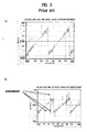
- FIG. 3 shows phase variations calculated in the case of general AWGN and long ghost environments
- FIG. 4 shows a plurality of SFO values estimated in acquisition and tracking modes of the sampling frequency
- FIG. 5 is a flow chart illustrating an SFO estimation algorithm according to the present invention.
- FIG. 6 is a flow chart illustrating an algorithm for estimating an SFO of more than 400ppm in the 2k mode or an SFO of more than 100ppm in the 8k mode according to the present invention
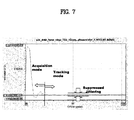
- FIG. 7 shows a variation in SFO values estimated by an SFO estimation algorithm according to the present invention.
- FIG. 8 is a block diagram illustrating an OFDM receiver according to the present invention.
- FIG. 5 is a flow chart illustrating an SFO estimation algorithm according to the present invention.
- an input estimation phase ⁇ x' l,kn is indicative of a phase value estimated by the phase estimator 40 shown in FIG. 2. Therefore, it should be understood that the SFO estimation algorithm shown in FIG. 5 is performed by the SFO calculator 50.
- the SFO calculator 50 determines whether a current frequency estimation mode is a tracking mode at step S10, because the overshoot caused by the deep fading greatly affects a desired SFO in the tracking mode as previously stated above.
- the SFO calculator 50 compares the estimated phase ⁇ x' l,kn with the magnitude of a predetermined input standard deviation ⁇ ph at step S30. It is preferable that the magnitude of the standard deviation ⁇ ph is 0.5rad. In this case, the standard deviation ⁇ ph is experimentally calculated.
- the SFO calculator 50 determines that overshoot occurs by the deep fading in the tracking mode, such that it compulsorily sets the estimated phase to zero.
- the above-mentioned operation is called a zero-focusing operation.
- a slope between phase data units i.e., an SFO denoted by a specific character " ⁇ " is calculated using the above-mentioned stored phase values at step S60.
- a phase overshoot caused by a ghost is zero-forced, such that the SFO can be correctly estimated even in the tracking mode.
- FIG. 6 is a flow chart illustrating an algorithm for estimating an SFO of more than 400ppm in the 2k mode or an SFO of more than 100ppm in the 8k mode according to the present invention.
- the SFO calculator 50 receives the calculated SFO ⁇ , and determines whether the received SFO value ⁇ is higher than an SFO threshold value at step S10.
- the SFO threshold value is indicative of a specific value of more than 400ppm in the 2k mode, and is indicative of a specific value of more than 100ppm in the 8k mode, as denoted by the following equation 3:
- the SFO calculator 50 discards the pilot phase information units of both ends, and re-calculates the SFO value using only a half the pilot phase information at step S20.
- the above-mentioned calculation process can be represented by the following equation 4:
- the SFO calculator 50 uses the calculated SFO value ⁇ without any change.
- FIG. 7 shows a variation in SFO values estimated by an SFO estimation algorithm according to the present invention.
- the jittering range is relatively reduced in the tracking mode on the condition that the SFO estimation algorithm is employed as compared to the graph shown in FIG. 4.
- the reduction of the jittering range in the tracking mode is equal to the ISI reduction of the reception signal, and is indicative of no constellation rotation.
- FIG. 8 is a block diagram illustrating an OFDM receiver according to the present invention.
- the OFDM receiver includes an analog front-end and ADC (Analog-to-Digital Converter) unit 100, a P/S (Parallel-to-Serial) unit 200, a resampler 300, a guard interval removal unit 400, an FFT (Fast Fourier Transform) unit 500, and SFO compensator 600, an FEQ (Freuqency-domain Equalizer) unit 700, and a guard removal unit 800.
- the analog front-end and ADC unit 100 performs a front-end process on a received analog signal, and converts the received analog signal into a digital signal.
- the P/S unit 200 converts a received parallel signal into a serial signal.
- the resampler 300 performs a sampling process on a received signal using the sampling frequency generated by the estimated SFO.
- the guard interval removal unit 400 removes a guard interval of the received signal from a time domain.
- the FFT unit 500 converts a time-domain signal into a frequency-domain signal.
- the SFO compensator 600 performs correct sampling synchronization on the frequency-domain signal acting as the output signal of the FFT unit 500.
- the FEQ 700 performs channel equalization in a frequency domain.
- the guard remover unit 800 removes a guard interval from the frequency domain.
- the SFO compensator 600 includes a CP extractor 610 for extracting a CP signal from the frequency-domain signal; a timing error detector 630 for receiving the extracted CP signal, and calculating a timing error value equal to the SFO value ⁇ using the extraction algorithm of the present invention; a loop filter (L/F) 650 for receiving the SFO value ⁇ , and accumulatively compensating for the received SFO value ⁇ ; and a numerical controlled oscillator (NCO) 670 for controlling a sampling frequency upon receiving the corrected SFO value ⁇ from the L/F 650.
- L/F loop filter
- NCO numerical controlled oscillator
- the resampler 300 performs the sampling process using the resultant SFO value correctly estimated by the above-mentioned inventive method, such that correct sampling synchronization is provided.
- the present invention is applicable to a DVB-T receiver and a DVB-H receiver.
- a method for estimating an SFO in a digital receiver, and an apparatus for compensating for a sampling frequency using the estimated SFO have the following effects.
- phase overshoot caused by a ghost is zero-forced (i.e., the phase overshoot is set to zero), such that a correct SFO can be estimated in the tracking mode.
- the SFO value can be correctly estimated although the estimated SFO is transitioned to 400ppm in the 2k mode or 100ppm in the 8k mode.
- the sampling frequency can be effectively compensated in the digital receiver.
Landscapes
- Engineering & Computer Science (AREA)
- Signal Processing (AREA)
- Computer Networks & Wireless Communication (AREA)
- Multimedia (AREA)
- Noise Elimination (AREA)
- Synchronisation In Digital Transmission Systems (AREA)
- Cable Transmission Systems, Equalization Of Radio And Reduction Of Echo (AREA)
Abstract
Description
- This application claims the benefit of Korean Patent Application No.10-2004-0065129, filed on August 18, 2004, which is hereby incorporated by reference as if fully set forth herein.
- The present invention relates to a digital receiver, and more particularly, to a method and apparatus for estimating an SFO (Sampling Frequency Offset) applicable to the digital receiver, and an apparatus for compensating for a sampling frequency using the estimated SFO.
- Generally, a DVB-T (Digital Video Broadcasting - Terrestrial) system acting as the European transmission standard for a terrestrial digital TV has generally selected an OFDM (Orthogonal Frequency Division Multiplexing) transmission scheme. It is well known in the art that the OFDM transmission scheme has very strong resistance to channel distortion caused by multiple paths (also called a multi-path) in a wireless broadband broadcast system.
- On the other hand, the OFDM transmission scheme has very weak resistance to synchronization. Therefore, if accurate synchronization is not established between a transmitter and a receiver, distortion of a reception signal occurs. In order to solve the above-mentioned problem, many developers have conducted intensive research into the improved OFDM transmission scheme.
- Particularly, if the receiver does not correctly perform sampling synchronization, an ISI (inter Symbol Interference) and a constellation rotation may occur in a reception signal, such that the receiver cannot demodulate the reception signal.
- In order to solve the above-mentioned problem, there has been newly proposed a method for estimating an SFO (Sampling Frequency Offset) using a CP (Continual Pilot) shown in FIG. 1.
- FIG. 1 shows general CP positions. As shown in FIG. 1, 45 pilots are employed during a 2k mode, and 177 pilots are employed during an 8k mode.
- For example, in the case of the 2k mode, a total of 1705 data subcarriers are present in one OFDM symbol interval. A pilot is located at each of subcarrier positions, for example, 0-th, 48-th, and 54-th subcarrier positions, etc. In this case, the pilot is positioned at the same subcarrier positions as the above subcarrier positions in the next OFDM symbol, such that the pilot will be referred to as a Continual Pilot (CP).
- A method for calculating the SFO using the above-mentioned CP information shown in FIG. 1 is shown in FIG. 2.
- FIG. 2 is a block diagram illustrating a conventional SFO estimation system.
- The above-mentioned conventional SFO estimation method will hereinafter be described with reference to FIG. 2. Firstly, the SFO estimation system receives a single signal Z l,k . The Z l,k signal is indicative of a k-th subcarrier in a first OFDM symbol. For example, in the case of the 2k mode shown in FIG. 1, the Z l,k signal is indicative of one pilot from among a plurality of pilots (i.e., 0-th, 48-th, and 53-th symbols, etc.) in the first OFDM symbol.
- The Z l,k signal is converted into another signal of Z l-1,k via a
delay 10. The Z l-1,k signal is converted into a conjugate root signal of
conjugate calculator 20. - Correlation between the Z l,k signal and the

multiplier 30, such that the multiplier 30 outputs a phase information signal of x l,k . By the followingequation 1 performed by aphase estimator 40, the phase information signal of x l,k acquires a total of 45 phase data units in the case of the 2k mode, and acquires a total of 177 phase data units in the case of the 8k mode. -

- An
SFO calculator 50 calculates a slope between phase data units using the phase data generated from thephase estimator 40, and calculates a mean slope, such that it calculates the SFO value. - The above-mentioned conventional SFO estimation method acquires correlation between two OFDM symbols, acquires a phase on the basis of the acquired correlation, and calculates a change rate of the acquired phase, such that it estimates the SFO value.
- However, the above-mentioned SFO estimation method may incur irregular overshoots of the phase due to a deep fading phenomenon in a long ghost environment as shown in FIG. 3b, whereas it easily estimates the SFO because a phase change rate is constant in an AWGN (Additive White Gaussian Noise) environment as shown in FIG. 3a.
- The above-mentioned irregular overshoots do not affect the SFO in an acquisition mode of a sampling frequency, but it greatly affects the SFO in a tracking mode of the sampling frequency as shown in FIG. 4.
- FIG. 4 shows a plurality of SFO values estimated in acquisition and tracking modes of the sampling frequency. As shown in FIG. 4, it can be recognized that a jittering range increases if overshoots occur in the tracking mode.
- In this manner, if the jittering range increases due to the overshoots in the tracking mode, the increased jittering range has a negative influence upon a method for compensating for a sampling frequency by estimating a correct SFO. Furthermore, assuming that an SFO of more than 400ppm occurs in the 2k mode of the long ghost environment or an SFO of more than 100ppm occurs in the 8k mode of the same long ghost environment, the conventional SFO estimation method has difficulty in correctly estimating the above-mentioned SFO values.
- Accordingly, the present invention is directed to a method and apparatus for estimating an SFO in a digital receiver, and a method and apparatus for compensating for a sampling frequency using the estimated SFO.
- An object of the present invention is to provide an SFO estimation method for efficiently estimating an SFO, and correctly estimating the SFO although the estimated SFO is transitioned to 400ppm in a 2k mode or 100ppm in an 8k mode.
- Another object of the present invention is to provide an apparatus for compensating for a sampling frequency using the estimated SFO.
- Additional advantages, objects, and features of the invention will be set forth in part in the description which follows and in part will become apparent to those having ordinary skill in the art upon examination of the following or may be learned from practice of the invention. The objectives and other advantages of the invention may be realized and attained by the structure particularly pointed out in the written description and claims hereof as well as the appended drawings.
- To achieve these objects and other advantages and in accordance with the purpose of the invention, as embodied and broadly described herein, a method for estimating an SFO (Sampling Frequency Offset) in a digital receiver to perform sampling synchronization, comprises the steps of (a) receiving an estimated phase, and comparing a magnitude of the estimated phase with that of a predetermined standard deviation; (b) if the magnitude of the estimated phase is greater than that of the predetermined standard deviation, compulsorily setting the estimated phase to zero, and storing the estimated phase of zero; and (c) calculating an SFO value using the stored phase.
- Preferably, the estimated phase is estimated using CP (Continual Pilot) information contained in a transmitted OFDM (Orthogonal Frequency Division Multiplexing) symbol.
- Preferably, the step (a) for comparing the estimated phase with the predetermined standard deviation is executed when a current frequency estimation mode is equal to a tracking mode. Preferably, if the frequency estimation mode is not equal to the tracking mode, the estimated phase is stored in a buffer, the SFO is calculated using the stored estimated phase.
- Preferably, the method further comprises the steps of: receiving the calculated SFO value, and comparing the received SFO value with an input SFO threshold value; if the calculated SFO value is higher than the SFO threshold value, re-calculating the SFO value using only a half pilot phase information.
- Preferably, the half the pilot phase information does not include both-end information of an inverted pilot phase.
- In another aspect of the present invention, there is provided an apparatus for estimating a sampling frequency offset (SFO) in a digital receiver to perform sampling synchronization, comprising a phase estimator for receiving phase information x l,k , and generating an estimated phase; and an SFO calculator for receiving the estimated phase, comparing a magnitude of the estimated phase with that of a predetermined standard deviation, compulsorily setting the estimated phase to zero if the magnitude of the estimated phase is greater than that of the predetermined standard deviation, and calculating an SFO value.
- In still another aspect of the present invention, there is provided a method for compensating for a sampling frequency in a digital receiver, comprising the steps of (a) extracting CP (Continual Pilot) information from a transmitted OFDM symbol;
(b) estimating a phase using the extracted CP information, compulsorily setting the estimated phase to zero if a magnitude of the estimated phase is greater than that of a predetermined standard deviation, calculating a SFO (Sampling Frequency Offset) value, and re-calculating the SFO value using only a half a pilot phase if the calculated SFO value is higher than a predetermined threshold value; (c) accumulatively compensating for the calculated SFO value; and (d) outputting a signal for controlling a sampling frequency using the accumulatively-compensated SFO value. - Therefore, the present invention performs zero-forcing on a phase overshoot caused by a ghost, such that a correct SFO can be estimated in the tracking mode.
- It is to be understood that both the foregoing general description and the following detailed description of the present invention are exemplary and explanatory and are intended to provide further explanation of the invention as claimed.
- The accompanying drawings, which are included to provide a further understanding of the invention and are incorporated in and constitute a part of this application, illustrate embodiment(s) of the invention and together with the description serve to explain the principle of the invention. In the drawings:
- FIG. 1 shows general CP positions;
- FIG. 2 is a block diagram illustrating a conventional SFO estimation system;
- FIG. 3 shows phase variations calculated in the case of general AWGN and long ghost environments;
- FIG. 4 shows a plurality of SFO values estimated in acquisition and tracking modes of the sampling frequency;
- FIG. 5 is a flow chart illustrating an SFO estimation algorithm according to the present invention;
- FIG. 6 is a flow chart illustrating an algorithm for estimating an SFO of more than 400ppm in the 2k mode or an SFO of more than 100ppm in the 8k mode according to the present invention;
- FIG. 7 shows a variation in SFO values estimated by an SFO estimation algorithm according to the present invention;
- FIG. 8 is a block diagram illustrating an OFDM receiver according to the present invention.
- Reference will now be made in detail to the preferred embodiments of the present invention, examples of which are illustrated in the accompanying drawings. Wherever possible, the same reference numbers will be used throughout the drawings to refer to the same or like parts.
- Prior to describing the present invention, it should be noted that most terms disclosed in the present invention correspond to general terms well known in the art, but some terms have been selected by the applicant as necessary and will hereinafter be disclosed in the following description of the present invention. Therefore, it is preferable that the terms defined by the applicant be understood on the basis of their meanings in the present invention.
- FIG. 5 is a flow chart illustrating an SFO estimation algorithm according to the present invention.
- As shown in FIG. 5, an input estimation phase ∠x' l,kn is indicative of a phase value estimated by the
phase estimator 40 shown in FIG. 2. Therefore, it should be understood that the SFO estimation algorithm shown in FIG. 5 is performed by theSFO calculator 50. - If the
SFO calculator 50 receives the estimated phase ∠x' l,kn , it determines whether a current frequency estimation mode is a tracking mode at step S10, because the overshoot caused by the deep fading greatly affects a desired SFO in the tracking mode as previously stated above. - If the frequency estimation mode is not equal to the tracking mode at step S10, the
SFO calculator 50 receives the estimated phase ∠x' l,kn , and stores the received phase ∠x' l,kn in an internal buffer as denoted by Φ l,n =∠x' l,kn at step S20. - If the frequency estimation mode is determined to be the tracking mode at step S10, the
SFO calculator 50 compares the estimated phase ∠x' l,kn with the magnitude of a predetermined input standard deviation σ ph at step S30. It is preferable that the magnitude of the standard deviation σ ph is 0.5rad. In this case, the standard deviation σ ph is experimentally calculated. - If the magnitude of the estimated phase ∠x' l,kn is greater than the magnitude of input standard deviation σ ph at step S30, the
SFO calculator 50 determines that overshoot occurs by the deep fading in the tracking mode, such that it compulsorily sets the estimated phase to zero. - The above-mentioned operation is called a zero-focusing operation. In other words, the estimated phase is compulsorily set to zero, and the resultant phase is stored in a buffer of the
SFO calculator 50 as denoted by Φ l,n =0 at step S40. - If the magnitude of the estimated phase is equal to or less than the magnitude of the standard deviation, the estimated phase is stored in the buffer as denoted by Φ l,n =∠x' l,kn at step S50.
- Thereafter, a slope between phase data units, i.e., an SFO denoted by a specific character "ζ", is calculated using the above-mentioned stored phase values at step S60. In other words, the
SFO calculator 50 calculates a slope among 45 pilot phases in the 2k mode, and calculates a slope among 177 pilot phases in the 8k mode as denoted by the following equation 2:
- In the case of calculating the SFO using the above-mentioned method, a phase overshoot caused by a ghost is zero-forced, such that the SFO can be correctly estimated even in the tracking mode.
- If the estimated SFO value is higher than a predetermined value of 400ppm in the 2k mode, or is higher than a predetermined value of 100ppm in the 8k mode, pilot phase information units of both ends are inverted from each other, such that it is difficult to estimate a correct SFO value. In order to solve the above-mentioned problem, there has been used a method shown in FIG. 6.
- FIG. 6 is a flow chart illustrating an algorithm for estimating an SFO of more than 400ppm in the 2k mode or an SFO of more than 100ppm in the 8k mode according to the present invention.
- Referring to FIG. 6, the
SFO calculator 50 receives the calculated SFO ζ, and determines whether the received SFO value ζ is higher than an SFO threshold value at step S10. In this case, the SFO threshold value is indicative of a specific value of more than 400ppm in the 2k mode, and is indicative of a specific value of more than 100ppm in the 8k mode, as denoted by the following equation 3: -

- If the calculated SFO value ζ is higher than the SFO threshold value at step S10, the
SFO calculator 50 discards the pilot phase information units of both ends, and re-calculates the SFO value using only a half the pilot phase information at step S20. The above-mentioned calculation process can be represented by the following equation 4: -

- Needless to say, if the calculated SFO value ζ is equal to or less than the SFO threshold value, the
SFO calculator 50 uses the calculated SFO value ζ without any change. - FIG. 7 shows a variation in SFO values estimated by an SFO estimation algorithm according to the present invention.
- As shown in FIG. 7, it can be recognized that the jittering range is relatively reduced in the tracking mode on the condition that the SFO estimation algorithm is employed as compared to the graph shown in FIG. 4. The reduction of the jittering range in the tracking mode is equal to the ISI reduction of the reception signal, and is indicative of no constellation rotation.
- FIG. 8 is a block diagram illustrating an OFDM receiver according to the present invention.
- Referring to FIG. 8, the OFDM receiver includes an analog front-end and ADC (Analog-to-Digital Converter)
unit 100, a P/S (Parallel-to-Serial)unit 200, aresampler 300, a guardinterval removal unit 400, an FFT (Fast Fourier Transform)unit 500, andSFO compensator 600, an FEQ (Freuqency-domain Equalizer)unit 700, and aguard removal unit 800. In more detail, the analog front-end andADC unit 100 performs a front-end process on a received analog signal, and converts the received analog signal into a digital signal. The P/S unit 200 converts a received parallel signal into a serial signal. Theresampler 300 performs a sampling process on a received signal using the sampling frequency generated by the estimated SFO. The guardinterval removal unit 400 removes a guard interval of the received signal from a time domain. TheFFT unit 500 converts a time-domain signal into a frequency-domain signal. The SFO compensator 600 performs correct sampling synchronization on the frequency-domain signal acting as the output signal of theFFT unit 500. TheFEQ 700 performs channel equalization in a frequency domain. Theguard remover unit 800 removes a guard interval from the frequency domain. - Particularly, the
SFO compensator 600 according to the present invention includes aCP extractor 610 for extracting a CP signal from the frequency-domain signal; atiming error detector 630 for receiving the extracted CP signal, and calculating a timing error value equal to the SFO value ζ using the extraction algorithm of the present invention; a loop filter (L/F) 650 for receiving the SFO value ζ, and accumulatively compensating for the received SFO value ζ; and a numerical controlled oscillator (NCO) 670 for controlling a sampling frequency upon receiving the corrected SFO value ζ from the L/F 650. - Therefore, the
resampler 300 performs the sampling process using the resultant SFO value correctly estimated by the above-mentioned inventive method, such that correct sampling synchronization is provided. - In the meantime, the present invention is applicable to a DVB-T receiver and a DVB-H receiver.
- As apparent from the above description, a method for estimating an SFO in a digital receiver, and an apparatus for compensating for a sampling frequency using the estimated SFO have the following effects.
- Firstly, a phase overshoot caused by a ghost is zero-forced (i.e., the phase overshoot is set to zero), such that a correct SFO can be estimated in the tracking mode.
- Secondly, the SFO value can be correctly estimated although the estimated SFO is transitioned to 400ppm in the 2k mode or 100ppm in the 8k mode.
- Thirdly, in the case of employing the correctly-estimated SFO value, the sampling frequency can be effectively compensated in the digital receiver.
- It will be apparent to those skilled in the art that various modifications and variations can be made in the present invention without departing from the spirit or scope of the inventions. Thus, it is intended that the present invention covers the modifications and variations of this invention provided they come within the scope of the appended claims and their equivalents.
Claims (20)
- A method for estimating an SFO (Sampling Frequency Offset) in a digital receiver to perform sampling synchronization, comprising the steps of:(a) receiving an estimated phase, and comparing a magnitude of the estimated phase with that of a predetermined standard deviation;(b) if the magnitude of the estimated phase is greater than that of the predetermined standard deviation, compulsorily setting the estimated phase to zero, and storing the estimated phase of zero; and(c) calculating an SFO value using the stored phase.
- The method according to claim 1, wherein the estimated phase is estimated using CP (Continual Pilot) information contained in a transmitted OFDM (Orthogonal Frequency Division Multiplexing) symbol.
- The method according to claim 1, wherein the step (a) for comparing the estimated phase with the predetermined standard deviation is executed when a current frequency estimation mode is equal to a tracking mode.
- The method according to claim 3, wherein:if the frequency estimation mode is not equal to the tracking mode, the estimated phase is stored in a buffer, the SFO is calculated using the stored estimated phase.
- The method according to claim 1, further comprising the step of:(d) if the estimated phase is equal to or less than the predetermined standard deviation, storing the estimated phase, an calculating the SFO using the stored phase.
- The method according to claim 1, wherein the predetermined standard deviation is 0.5rad.
- The method according to claim 1, wherein the step (c) for calculating the SFO includes the steps of:calculating a slope between individual data units of the estimated phase, and calculating a mean value of the calculated slope.
- The method according to claim 1, further comprising the steps of:(e) receiving the calculated SFO value, and comparing the received SFO value with an input SFO threshold value; and(f) if the calculated SFO value is higher than the SFO threshold value, re-calculating the SFO value using only a half pilot phase information.
- The method according to claim 8, wherein the half the pilot phase information does not include both-end information of an inverted pilot phase.
- The method according to claim 8, further comprising the step of:if the calculated SFO value is less than the SFO threshold value, omitting the step (f) for re-calculating the SFO value.
- The method according to claim 8, wherein the SFO threshold value is 400ppm in a 2k mode.
- The method according to claim 8, wherein the SFO threshold value is 100ppm in an 8k mode.
- A method for estimating a sampling frequency offset (SFO) in a digital receiver to perform sampling synchronization, comprising the steps of:(a) receiving an estimated phase, and determining whether a current frequency estimation mode is a tracking mode;(b) if the current frequency estimation mode is the tracking mode, comparing a magnitude of the estimated phase with that of a predetermined standard deviation;(c) if the magnitude of the estimated phase is greater than that of the predetermined standard deviation, compulsorily setting the estimated phase to zero, and storing the estimated phase of zero;(d) calculating an SFO value using the stored phase;(e) receiving the calculated SFO value, and comparing the received SFO value with an input SFO threshold value; and(f) if the calculated SFO value is higher than the SFO threshold value, re-calculating the SFO value using only a half pilot phase information.
- An apparatus for estimating a sampling frequency offset (SFO) in a digital receiver to perform sampling synchronization, comprising:a phase estimator for receiving phase information x l,k , and generating an estimated phase; andan SFO calculator for receiving the estimated phase, comparing a magnitude of the estimated phase with that of a predetermined standard deviation, compulsorily setting the estimated phase to zero if the magnitude of the estimated phase is greater than that of the predetermined standard deviation, and calculating an SFO value.
- The apparatus according to claim 14, wherein the SFO calculator receives the calculated SFO value, comparing the received SFO value with a predetermined threshold value, and re-calculating the SFO value using only a half pilot phase information if the calculated SFO value is higher than the SFO threshold value.
- The apparatus according to claim 15, wherein the SFO threshold value is 400ppm in a 2k mode.
- The apparatus according to claim 15, wherein the SFO threshold value is 100ppm in an 8k mode.
- The apparatus according to claim 14, wherein the predetermined standard deviation is 0.5rad.
- A method for compensating for a sampling frequency in a digital receiver, comprising the steps of:(a) extracting CP (Continual Pilot) information from a transmitted OFDM symbol;(b) estimating a phase using the extracted CP information, compulsorily setting the estimated phase to zero if a magnitude of the estimated phase is greater than that of a predetermined standard deviation, calculating a SFO (Sampling Frequency Offset) value, and re-calculating the SFO value using only a half a pilot phase if the calculated SFO value is higher than a predetermined threshold value;(c) accumulatively compensating for the calculated SFO value; and(d) outputting a signal for controlling a sampling frequency using the accumulatively-compensated SFO value.
- An apparatus for compensating for a sampling frequency in a digital receiver, comprising:a CP (Continual Pilot) for extracting CP information from a transmitted OFDM symbol;a timing error detector for estimating a phase using the extracted CP information, compulsorily setting the estimated phase to zero if a magnitude of the estimated phase is greater than that of a predetermined standard deviation, calculating a SFO (Sampling Frequency Offset) value, and re-calculating the SFO value using only a half a pilot phase if the calculated SFO value is higher than a predetermined threshold value;a loop filter (L/F) for accumulatively compensating for the calculated SFO value; anda numerical controlled oscillator (NCO) for controlling a sampling frequency upon receiving the accumulatively-compensated SFO value.
Applications Claiming Priority (1)
| Application Number | Priority Date | Filing Date | Title |
|---|---|---|---|
| KR1020040065129A KR101087096B1 (en) | 2004-08-18 | 2004-08-18 | SFO estimation method of digital receiver and sampling frequency correction apparatus using estimated SFO |
Publications (2)
| Publication Number | Publication Date |
|---|---|
| EP1628451A2 true EP1628451A2 (en) | 2006-02-22 |
| EP1628451A3 EP1628451A3 (en) | 2007-10-31 |
Family
ID=35376940
Family Applications (1)
| Application Number | Title | Priority Date | Filing Date |
|---|---|---|---|
| EP05291742A Withdrawn EP1628451A3 (en) | 2004-08-18 | 2005-08-17 | Method and apparatus for estimating sampling frequency offset and for compensating said sampling frequency offset in a digital receiver |
Country Status (3)
| Country | Link |
|---|---|
| US (1) | US7573953B2 (en) |
| EP (1) | EP1628451A3 (en) |
| KR (1) | KR101087096B1 (en) |
Families Citing this family (9)
| Publication number | Priority date | Publication date | Assignee | Title |
|---|---|---|---|---|
| US20070053462A1 (en) * | 2005-09-06 | 2007-03-08 | Pirooz Ali D | Sampling frequency offset estimation and correction system and method for ultra wideband ofdm |
| CN101277284B (en) * | 2007-03-29 | 2012-12-26 | 深圳赛意法微电子有限公司 | Estimation method of sampling clock frequency offset in DRM and integrated chip |
| KR101339424B1 (en) * | 2007-07-16 | 2013-12-09 | 삼성전자주식회사 | method and apparatus of estimating sampling frequency offset, and sampling timing recovery loop having the apparatus |
| KR101523710B1 (en) * | 2008-08-26 | 2015-05-28 | 삼성전자주식회사 | Apparatus and method for correcting phase offset of orthogonal frequency division multiplexing system |
| US8357628B2 (en) | 2008-08-29 | 2013-01-22 | Agilent Technologies, Inc. | Inorganic/organic hybrid totally porous metal oxide particles, methods for making them and separation devices using them |
| JP5278173B2 (en) * | 2009-06-04 | 2013-09-04 | ソニー株式会社 | Receiving apparatus and method, program, and receiving system |
| US9246734B1 (en) * | 2015-02-27 | 2016-01-26 | Qualcomm Technologies International, Ltd. | Method and apparatus for sample frequency offset correction OFDM and single carrier frequency domain equalized receiver systems |
| GB2539018B (en) * | 2015-06-03 | 2019-11-06 | Imagination Tech Ltd | Sampling frequency offset calculation |
| CN109327848B (en) * | 2018-09-12 | 2021-08-13 | 天津大学 | A wireless buffer resource optimization method using zero-forcing beamforming |
Family Cites Families (9)
| Publication number | Priority date | Publication date | Assignee | Title |
|---|---|---|---|---|
| SG44793A1 (en) * | 1991-12-07 | 1997-12-19 | Philips Electronics Nv | Mobile radio receiver for a radio transmission system |
| US5343498A (en) * | 1993-03-08 | 1994-08-30 | General Electric Company | Sample timing selection and frequency offset correction for U.S. digital cellular mobile receivers |
| US6577690B1 (en) | 1998-06-25 | 2003-06-10 | Silicon Automation Systems Limited | Clock recovery in multi-carrier transmission systems |
| FR2787620B1 (en) | 1998-12-22 | 2001-03-09 | Franco Belge Combustibles | LOADING SYSTEM FOR A NUCLEAR FUEL ASSEMBLY |
| US6459745B1 (en) * | 1999-09-23 | 2002-10-01 | The United States Of America As Represented By The Secretary Of The Navy | Frequency/timing recovery circuit for orthogonal frequency division multiplexed signals |
| US6683903B1 (en) * | 2000-04-27 | 2004-01-27 | Motorola, Inc. | Method and apparatus for synchronization within a spread-spectrum communication system |
| KR100376804B1 (en) * | 2000-09-29 | 2003-03-19 | 삼성전자주식회사 | Apparatus for compensating frequency offset and method thereof in orthogonal frequency division multiplexing system |
| US7304545B1 (en) * | 2000-11-30 | 2007-12-04 | Marvell International Ltd. | High latency timing circuit |
| DE60125506T2 (en) * | 2001-02-26 | 2007-10-04 | Juniper Networks, Inc., Sunnyvale | Estimation of frequency offset for use with short bursts of data |
-
2004
- 2004-08-18 KR KR1020040065129A patent/KR101087096B1/en not_active Expired - Fee Related
-
2005
- 2005-08-17 US US11/205,561 patent/US7573953B2/en not_active Expired - Fee Related
- 2005-08-17 EP EP05291742A patent/EP1628451A3/en not_active Withdrawn
Non-Patent Citations (2)
| Title |
|---|
| KIM Y-J ET AL.: "A new FAST SYMBOL TIMING RECOVERY ALGORITHM FOR OFDM SYSTEMS", IEEE TRANSACTIONS ON CONSUMER ELECTRONICS, IEEE SERVICE CENTER, vol. 44, no. 3, August 1998 (1998-08-01) |
| STUBER G.L. ET AL: "Broadband MIMO-OFDM Wireless Communications", PROCEEDINGS OF THE IEEE, vol. 92, no. 2, 1 February 2004 (2004-02-01), IEEE. NEW YORK, US, pages 271 - 294, XP011107745 * |
Also Published As
| Publication number | Publication date |
|---|---|
| EP1628451A3 (en) | 2007-10-31 |
| KR101087096B1 (en) | 2011-11-25 |
| US20060039507A1 (en) | 2006-02-23 |
| US7573953B2 (en) | 2009-08-11 |
| KR20060016622A (en) | 2006-02-22 |
Similar Documents
| Publication | Publication Date | Title |
|---|---|---|
| CN101507219B (en) | Method and system for time error estimation for data symbols | |
| US7649963B2 (en) | Apparatus for estimating and compensating carrier frequency offset and data receiving method in receiver of wireless communication system | |
| US8437426B2 (en) | Receiving apparatus, receiving method, and program | |
| US20090168641A1 (en) | Method and circuit for frequency offset estimation in frequency domain in the orthogonal frequency division multiplexing baseband receiver for ieee 802.11a/g wireless lan standard | |
| US20080198942A1 (en) | Long echo detection and channel estimation for ofdm systems | |
| EP1628450A2 (en) | Frequency recovery apparatus and mobile broadcast receiver using the frequency recovery apparatus | |
| KR20070056881A (en) | Frequency Restoration Apparatus and Method in Orthogonal Frequency Multiple Access System | |
| EP1480401A2 (en) | Frequency-offset estimator for multi-carrier reception | |
| KR100719111B1 (en) | Phase Noise Compensation Apparatus and Method Applied to OPDM System | |
| US20100046359A1 (en) | Wireless Terminal, Base Station and Channel Characteristic Estimating Method | |
| EP1633098B1 (en) | Carrier Synchronization in OFDM | |
| US7573953B2 (en) | Method and apparatus for estimating SFO in digital receiver, and method and apparatus for compensating for sampling frequency using the estimated SFO in the digital receiver | |
| Chen et al. | Mode detection, synchronization, and channel estimation for DVB-T OFDM receiver | |
| US20100074346A1 (en) | Channel estimation in ofdm receivers | |
| US20090274223A1 (en) | Orthogonal frequency division multiplexing receiver | |
| JP2009111748A (en) | Receiving device, receiving method, and program | |
| JP2009519664A (en) | Method and system for estimating symbol time error in a broadband transmission system | |
| WO2006065016A1 (en) | Method for estimating frequency/time offset and apparatus using the same in ofdm communication system | |
| US7333792B2 (en) | Multi-carrier receiving method and apparatus | |
| US8447002B2 (en) | Receiving apparatus with frequency domain equalizer | |
| WO2007072348A2 (en) | A method for signal reception in a ofdm system | |
| EP1387544B1 (en) | Synchronisation in multicarrier receivers | |
| KR100514297B1 (en) | Apparatus and method for compensating residual frequency offset of wireless local area network system | |
| JP5072680B2 (en) | Receiving method and apparatus | |
| KR100697526B1 (en) | Tracking device of digital broadcasting receiver |
Legal Events
| Date | Code | Title | Description |
|---|---|---|---|
| PUAI | Public reference made under article 153(3) epc to a published international application that has entered the european phase |
Free format text: ORIGINAL CODE: 0009012 |
|
| 17P | Request for examination filed |
Effective date: 20050823 |
|
| AK | Designated contracting states |
Kind code of ref document: A2 Designated state(s): AT BE BG CH CY CZ DE DK EE ES FI FR GB GR HU IE IS IT LI LT LU LV MC NL PL PT RO SE SI SK TR |
|
| AX | Request for extension of the european patent |
Extension state: AL BA HR MK YU |
|
| PUAL | Search report despatched |
Free format text: ORIGINAL CODE: 0009013 |
|
| AK | Designated contracting states |
Kind code of ref document: A3 Designated state(s): AT BE BG CH CY CZ DE DK EE ES FI FR GB GR HU IE IS IT LI LT LU LV MC NL PL PT RO SE SI SK TR |
|
| AX | Request for extension of the european patent |
Extension state: AL BA HR MK YU |
|
| 17Q | First examination report despatched |
Effective date: 20080415 |
|
| AKX | Designation fees paid |
Designated state(s): AT BE BG CH CY CZ DE DK EE ES FI FR GB GR HU IE IS IT LI LT LU LV MC NL PL PT RO SE SI SK TR |
|
| GRAP | Despatch of communication of intention to grant a patent |
Free format text: ORIGINAL CODE: EPIDOSNIGR1 |
|
| STAA | Information on the status of an ep patent application or granted ep patent |
Free format text: STATUS: THE APPLICATION IS DEEMED TO BE WITHDRAWN |
|
| 18D | Application deemed to be withdrawn |
Effective date: 20100601 |