EP1628092A2 - Air conditioning system combined with an electricity generating system - Google Patents
Air conditioning system combined with an electricity generating system Download PDFInfo
- Publication number
- EP1628092A2 EP1628092A2 EP05001040A EP05001040A EP1628092A2 EP 1628092 A2 EP1628092 A2 EP 1628092A2 EP 05001040 A EP05001040 A EP 05001040A EP 05001040 A EP05001040 A EP 05001040A EP 1628092 A2 EP1628092 A2 EP 1628092A2
- Authority
- EP
- European Patent Office
- Prior art keywords
- heat
- cooling water
- heat exchanger
- engine
- line
- Prior art date
- Legal status (The legal status is an assumption and is not a legal conclusion. Google has not performed a legal analysis and makes no representation as to the accuracy of the status listed.)
- Withdrawn
Links
Images


Classifications
-
- F—MECHANICAL ENGINEERING; LIGHTING; HEATING; WEAPONS; BLASTING
- F25—REFRIGERATION OR COOLING; COMBINED HEATING AND REFRIGERATION SYSTEMS; HEAT PUMP SYSTEMS; MANUFACTURE OR STORAGE OF ICE; LIQUEFACTION SOLIDIFICATION OF GASES
- F25B—REFRIGERATION MACHINES, PLANTS OR SYSTEMS; COMBINED HEATING AND REFRIGERATION SYSTEMS; HEAT PUMP SYSTEMS
- F25B13/00—Compression machines, plants or systems, with reversible cycle
-
- F—MECHANICAL ENGINEERING; LIGHTING; HEATING; WEAPONS; BLASTING
- F25—REFRIGERATION OR COOLING; COMBINED HEATING AND REFRIGERATION SYSTEMS; HEAT PUMP SYSTEMS; MANUFACTURE OR STORAGE OF ICE; LIQUEFACTION SOLIDIFICATION OF GASES
- F25B—REFRIGERATION MACHINES, PLANTS OR SYSTEMS; COMBINED HEATING AND REFRIGERATION SYSTEMS; HEAT PUMP SYSTEMS
- F25B30/00—Heat pumps
-
- F—MECHANICAL ENGINEERING; LIGHTING; HEATING; WEAPONS; BLASTING
- F02—COMBUSTION ENGINES; HOT-GAS OR COMBUSTION-PRODUCT ENGINE PLANTS
- F02C—GAS-TURBINE PLANTS; AIR INTAKES FOR JET-PROPULSION PLANTS; CONTROLLING FUEL SUPPLY IN AIR-BREATHING JET-PROPULSION PLANTS
- F02C6/00—Plural gas-turbine plants; Combinations of gas-turbine plants with other apparatus; Adaptations of gas-turbine plants for special use
- F02C6/18—Plural gas-turbine plants; Combinations of gas-turbine plants with other apparatus; Adaptations of gas-turbine plants for special use using the waste heat of gas-turbine plants outside the plants themselves, e.g. gas-turbine power heat plants
-
- F—MECHANICAL ENGINEERING; LIGHTING; HEATING; WEAPONS; BLASTING
- F24—HEATING; RANGES; VENTILATING
- F24F—AIR-CONDITIONING; AIR-HUMIDIFICATION; VENTILATION; USE OF AIR CURRENTS FOR SCREENING
- F24F1/00—Room units for air-conditioning, e.g. separate or self-contained units or units receiving primary air from a central station
-
- F—MECHANICAL ENGINEERING; LIGHTING; HEATING; WEAPONS; BLASTING
- F25—REFRIGERATION OR COOLING; COMBINED HEATING AND REFRIGERATION SYSTEMS; HEAT PUMP SYSTEMS; MANUFACTURE OR STORAGE OF ICE; LIQUEFACTION SOLIDIFICATION OF GASES
- F25B—REFRIGERATION MACHINES, PLANTS OR SYSTEMS; COMBINED HEATING AND REFRIGERATION SYSTEMS; HEAT PUMP SYSTEMS
- F25B27/00—Machines, plants or systems, using particular sources of energy
-
- F—MECHANICAL ENGINEERING; LIGHTING; HEATING; WEAPONS; BLASTING
- F25—REFRIGERATION OR COOLING; COMBINED HEATING AND REFRIGERATION SYSTEMS; HEAT PUMP SYSTEMS; MANUFACTURE OR STORAGE OF ICE; LIQUEFACTION SOLIDIFICATION OF GASES
- F25B—REFRIGERATION MACHINES, PLANTS OR SYSTEMS; COMBINED HEATING AND REFRIGERATION SYSTEMS; HEAT PUMP SYSTEMS
- F25B40/00—Subcoolers, desuperheaters or superheaters
- F25B40/04—Desuperheaters
-
- F—MECHANICAL ENGINEERING; LIGHTING; HEATING; WEAPONS; BLASTING
- F25—REFRIGERATION OR COOLING; COMBINED HEATING AND REFRIGERATION SYSTEMS; HEAT PUMP SYSTEMS; MANUFACTURE OR STORAGE OF ICE; LIQUEFACTION SOLIDIFICATION OF GASES
- F25B—REFRIGERATION MACHINES, PLANTS OR SYSTEMS; COMBINED HEATING AND REFRIGERATION SYSTEMS; HEAT PUMP SYSTEMS
- F25B40/00—Subcoolers, desuperheaters or superheaters
- F25B40/06—Superheaters
-
- F—MECHANICAL ENGINEERING; LIGHTING; HEATING; WEAPONS; BLASTING
- F28—HEAT EXCHANGE IN GENERAL
- F28D—HEAT-EXCHANGE APPARATUS, NOT PROVIDED FOR IN ANOTHER SUBCLASS, IN WHICH THE HEAT-EXCHANGE MEDIA DO NOT COME INTO DIRECT CONTACT
- F28D7/00—Heat-exchange apparatus having stationary tubular conduit assemblies for both heat-exchange media, the media being in contact with different sides of a conduit wall
-
- F—MECHANICAL ENGINEERING; LIGHTING; HEATING; WEAPONS; BLASTING
- F25—REFRIGERATION OR COOLING; COMBINED HEATING AND REFRIGERATION SYSTEMS; HEAT PUMP SYSTEMS; MANUFACTURE OR STORAGE OF ICE; LIQUEFACTION SOLIDIFICATION OF GASES
- F25B—REFRIGERATION MACHINES, PLANTS OR SYSTEMS; COMBINED HEATING AND REFRIGERATION SYSTEMS; HEAT PUMP SYSTEMS
- F25B2313/00—Compression machines, plants or systems with reversible cycle not otherwise provided for
- F25B2313/023—Compression machines, plants or systems with reversible cycle not otherwise provided for using multiple indoor units
- F25B2313/0233—Compression machines, plants or systems with reversible cycle not otherwise provided for using multiple indoor units in parallel arrangements
-
- F25B2327/001—
-
- F—MECHANICAL ENGINEERING; LIGHTING; HEATING; WEAPONS; BLASTING
- F25—REFRIGERATION OR COOLING; COMBINED HEATING AND REFRIGERATION SYSTEMS; HEAT PUMP SYSTEMS; MANUFACTURE OR STORAGE OF ICE; LIQUEFACTION SOLIDIFICATION OF GASES
- F25B—REFRIGERATION MACHINES, PLANTS OR SYSTEMS; COMBINED HEATING AND REFRIGERATION SYSTEMS; HEAT PUMP SYSTEMS
- F25B2327/00—Compressor driving means
- F25B2327/10—Compressor driving means using engines
- F25B2327/12—Compressor driving means using engines using internal combustion engines
-
- F—MECHANICAL ENGINEERING; LIGHTING; HEATING; WEAPONS; BLASTING
- F25—REFRIGERATION OR COOLING; COMBINED HEATING AND REFRIGERATION SYSTEMS; HEAT PUMP SYSTEMS; MANUFACTURE OR STORAGE OF ICE; LIQUEFACTION SOLIDIFICATION OF GASES
- F25B—REFRIGERATION MACHINES, PLANTS OR SYSTEMS; COMBINED HEATING AND REFRIGERATION SYSTEMS; HEAT PUMP SYSTEMS
- F25B2400/00—Component parts or details not otherwise provided for in this subclass
- F25B2400/06—Several compression cycles arranged in parallel
-
- F—MECHANICAL ENGINEERING; LIGHTING; HEATING; WEAPONS; BLASTING
- F25—REFRIGERATION OR COOLING; COMBINED HEATING AND REFRIGERATION SYSTEMS; HEAT PUMP SYSTEMS; MANUFACTURE OR STORAGE OF ICE; LIQUEFACTION SOLIDIFICATION OF GASES
- F25B—REFRIGERATION MACHINES, PLANTS OR SYSTEMS; COMBINED HEATING AND REFRIGERATION SYSTEMS; HEAT PUMP SYSTEMS
- F25B2400/00—Component parts or details not otherwise provided for in this subclass
- F25B2400/07—Details of compressors or related parts
- F25B2400/075—Details of compressors or related parts with parallel compressors
-
- F—MECHANICAL ENGINEERING; LIGHTING; HEATING; WEAPONS; BLASTING
- F25—REFRIGERATION OR COOLING; COMBINED HEATING AND REFRIGERATION SYSTEMS; HEAT PUMP SYSTEMS; MANUFACTURE OR STORAGE OF ICE; LIQUEFACTION SOLIDIFICATION OF GASES
- F25B—REFRIGERATION MACHINES, PLANTS OR SYSTEMS; COMBINED HEATING AND REFRIGERATION SYSTEMS; HEAT PUMP SYSTEMS
- F25B2500/00—Problems to be solved
- F25B2500/02—Increasing the heating capacity of a reversible cycle during cold outdoor conditions
-
- Y—GENERAL TAGGING OF NEW TECHNOLOGICAL DEVELOPMENTS; GENERAL TAGGING OF CROSS-SECTIONAL TECHNOLOGIES SPANNING OVER SEVERAL SECTIONS OF THE IPC; TECHNICAL SUBJECTS COVERED BY FORMER USPC CROSS-REFERENCE ART COLLECTIONS [XRACs] AND DIGESTS
- Y02—TECHNOLOGIES OR APPLICATIONS FOR MITIGATION OR ADAPTATION AGAINST CLIMATE CHANGE
- Y02A—TECHNOLOGIES FOR ADAPTATION TO CLIMATE CHANGE
- Y02A30/00—Adapting or protecting infrastructure or their operation
- Y02A30/27—Relating to heating, ventilation or air conditioning [HVAC] technologies
- Y02A30/274—Relating to heating, ventilation or air conditioning [HVAC] technologies using waste energy, e.g. from internal combustion engine
-
- Y—GENERAL TAGGING OF NEW TECHNOLOGICAL DEVELOPMENTS; GENERAL TAGGING OF CROSS-SECTIONAL TECHNOLOGIES SPANNING OVER SEVERAL SECTIONS OF THE IPC; TECHNICAL SUBJECTS COVERED BY FORMER USPC CROSS-REFERENCE ART COLLECTIONS [XRACs] AND DIGESTS
- Y02—TECHNOLOGIES OR APPLICATIONS FOR MITIGATION OR ADAPTATION AGAINST CLIMATE CHANGE
- Y02E—REDUCTION OF GREENHOUSE GAS [GHG] EMISSIONS, RELATED TO ENERGY GENERATION, TRANSMISSION OR DISTRIBUTION
- Y02E20/00—Combustion technologies with mitigation potential
- Y02E20/14—Combined heat and power generation [CHP]
-
- Y—GENERAL TAGGING OF NEW TECHNOLOGICAL DEVELOPMENTS; GENERAL TAGGING OF CROSS-SECTIONAL TECHNOLOGIES SPANNING OVER SEVERAL SECTIONS OF THE IPC; TECHNICAL SUBJECTS COVERED BY FORMER USPC CROSS-REFERENCE ART COLLECTIONS [XRACs] AND DIGESTS
- Y02—TECHNOLOGIES OR APPLICATIONS FOR MITIGATION OR ADAPTATION AGAINST CLIMATE CHANGE
- Y02P—CLIMATE CHANGE MITIGATION TECHNOLOGIES IN THE PRODUCTION OR PROCESSING OF GOODS
- Y02P80/00—Climate change mitigation technologies for sector-wide applications
- Y02P80/10—Efficient use of energy, e.g. using compressed air or pressurized fluid as energy carrier
- Y02P80/15—On-site combined power, heat or cool generation or distribution, e.g. combined heat and power [CHP] supply
-
- Y—GENERAL TAGGING OF NEW TECHNOLOGICAL DEVELOPMENTS; GENERAL TAGGING OF CROSS-SECTIONAL TECHNOLOGIES SPANNING OVER SEVERAL SECTIONS OF THE IPC; TECHNICAL SUBJECTS COVERED BY FORMER USPC CROSS-REFERENCE ART COLLECTIONS [XRACs] AND DIGESTS
- Y02—TECHNOLOGIES OR APPLICATIONS FOR MITIGATION OR ADAPTATION AGAINST CLIMATE CHANGE
- Y02T—CLIMATE CHANGE MITIGATION TECHNOLOGIES RELATED TO TRANSPORTATION
- Y02T10/00—Road transport of goods or passengers
- Y02T10/10—Internal combustion engine [ICE] based vehicles
- Y02T10/12—Improving ICE efficiencies
Definitions
- the present invention relates to a cogeneration system in which both the electricity and waste heat generated from an engine are used, and, more particularly, to a cogeneration system in which waste heat generated from an engine is supplied to suction and discharge sides of a compressor and to an outdoor heat exchanger to achieve an enhancement in heating performance.
- cogeneration systems are adapted to generate both electricity and heat from a single energy source.
- Such a cogeneration system can recover heat of exhaust gas or waste heat of cooling water generated from an engine or turbine during an electricity generation operation, so that the cogeneration system can achieve an increase in energy efficiency of 70 to 80% over other systems.
- the cogeneration system has recently been highlighted as an electricity and heat supply source for buildings.
- the cogeneration system exhibits highly-efficient energy utilization in that the recovered waste heat is mainly used to heat/cool a confined space and to heat water.
- FIG. 1 is a schematic configuration diagram illustrating a conventional cogeneration system used in a heating/cooling apparatus.
- the conventional cogeneration system includes a gas engine 1, and a generator 3, which is driven by a driving force outputted from the gas engine 1, to generate electricity.
- the electricity generated from the generator 3 is used in a variety of devices including a cooling/heating unit 20, illumination devices, and other electrical products.
- waste heat generated from the gas engine 1 that is, heat of cooling water generated when the cooling water cools the gas engine 1, and heat of exhaust gas generated from the gas engine 1, is used during a heating operation of the cooling/heating unit 20.
- the cooling/heating unit 20 is of a heat pump type so that the cooling/heating unit 20 not only can be used as a cooling unit, but also can be used as a heating unit in a state in which the refrigerant flow direction in the refrigerant cycle is reversed.
- the cooling/heating unit 20 includes a compressor 21, a four-way valve 23, an outdoor heat exchanger 25, an outdoor fan 26, an expansion device 27, and an indoor heat exchanger 29.
- an air pre-heating heat exchanger 30 is arranged at the side of the outdoor heat exchanger 25 to preheat air passing around the outdoor heat exchanger 25 during a heating operation of the cooling/heating unit 20, using the waste heat of the gas engine 1.
- the cogeneration system In order to supply the waste heat to the cooling/heating unit 20, the cogeneration system also includes a cooling water heat exchanger 5 to recover the heat of the cooling water used to cool the gas engine 1, and an exhaust gas heat exchanger 9 arranged at an exhaust conduit 7 to recover the heat of the exhaust gas.
- the cooling water heat exchanger 5 and exhaust gas heat exchanger 9 are connected to the air pre-heating heat exchanger 30 of the cooling/heating unit 20 by a heat transfer line 11, through which a heat transfer medium flows, so as to supply waste heat to the air pre-heating heat exchanger 30 during the heating operation of the cooling/heating unit 20.
- the' cogeneration system recovers engine heat and exhaust gas heat, pre-heats outdoor air through the air pre-heating heat exchanger 30, using the recovered heat, and causes the pre-heated air to perform heat exchange with the outdoor heat exchanger 25, thereby preventing a degradation in the heating performance of the cooling/heating unit 20, which may occur when the temperature of the outdoor air is low.
- the cooling/heating unit 20 When the cooling/heating unit 20 operates in a cooling mode, the flow path of the heat transfer medium is changed to communicate with a radiating line 13, which is connected to the heat transfer line 11, because it is unnecessary to supply waste heat.
- the waste heat is discharged to the atmosphere through a radiator 17, which includes a heat exchanger 15 and a radiator fan 16, or is supplied to and used in a water heater, a hot water supplier, or other systems.
- reference character P designates pumps, each serving to force the heat transfer medium to flow through an associated portion of the heat transfer line 11
- reference character V designates valves, each serving to switch the flow path of the heat transfer medium between the heat transfer line 11 and the radiating line 13.
- the conventional cogeneration system since the waste heat generated from the gas engine 1 is used only to pre-heat the outdoor heat exchanger 25 through the air pre-heating heat exchanger 30, the conventional cogeneration system has a limitation in enhancing the heating performance during the heating operation.
- the present invention has been made in view of the above-mentioned problem, and it is an object of the invention to provide a cogeneration system in which waste heat generated from an engine is supplied not only to suction and discharge sides of a compressor, but also to an outdoor heat exchanger to pre-heat a refrigerant passing through the outdoor heat exchanger, thereby achieving an enhancement in heating performance during a heating operation.
- the present invention provides a cogeneration system comprising: an engine, which drives a generator to generate electricity; a cooling/heating unit, which comprises at least one compressor, a four-way valve, an outdoor heat exchanger, an expansion device, and an indoor heat exchanger, to establish a heat pump type refrigerant cycle; a cooling water heat supplier to supply heat of cooling water used to cool the engine to a suction side of the compressor of the cooling/heating unit and to pre-heat air passing through the outdoor heat exchanger; and a discharge-side refrigerant over-heater to supply heat of exhaust gas discharged from the engine to a discharge side of the compressor.
- the cooling water heat supplier may comprise a suction-side over-heating heat exchanger to perform heat exchange between a suction-side refrigerant line of the compressor and a cooling water line to transfer the cooling water heat of the engine, and a pre-heating heat exchanger arranged at an air flow zone of the outdoor heat exchanger to receive the cooling water heat of the engine, and thus, to pre-heat outdoor air.
- the cooling water heat supplier may further comprise a cooling water heat exchanger connected to the engine via the cooling water line to recover the cooling water heat of the engine.
- the suction-side over-heating heat exchanger and the pre-heating heat exchanger may receive the cooling water heat from the cooling water heat exchanger.
- the cogeneration system may further comprise a cooling water heat radiating unit arranged at the cooling water line, which extends from the engine to the cooling water heat exchanger, to radiate the heat of the cooling water.
- the cooling water heat supplier may primarily receive the cooling water heat through the suction-side over-heating heat exchanger, and may secondarily receive the cooling water heat through the pre-heating heat exchanger.
- the cooling water heat supplier may further comprise a bypass line branched from the suction-side refrigerant line of the compressor, and a valve arranged in the suction-side refrigerant line to change a refrigerant path between the suction-side refrigerant line and the bypass line, whereby the refrigerant bypass line and the valve function to cause a refrigerant in the suction-side refrigerant line to flow without passing through the suction-side over-heating heat exchanger.
- the discharge-side refrigerant over-heater may comprise an exhaust gas heat exchanger arranged at an exhaust conduit of the engine to recover the exhaust gas heat, and a discharge-side over-heating heat exchanger to perform heat exchange between a line to receive the heat recovered by the exhaust gas heat exchanger and a discharge-side refrigerant line of the compressor.
- the discharge-side refrigerant over-heater may further comprise a bypass line branched from the discharge-side refrigerant line of the compressor, and a valve arranged in the discharge-side refrigerant line to change a refrigerant path between the discharge-side refrigerant line and the bypass line, whereby the refrigerant bypass line and the valve function to cause a refrigerant in the discharge-side refrigerant line to flow without passing through the discharge-side over-heating heat exchanger.
- the present invention provides a cogeneration system comprising: an engine, which drives a generator to generate electricity; a cooling/heating unit, which comprises at least one compressor, a four-way valve , an outdoor heat exchanger, an expansion device, and an indoor heat exchanger, to establish a heat pump type refrigerant cycle; and a cooling water heat supplier to primarily supply heat of cooling water used to cool the engine to a suction side of the compressor of the cooling/heating unit, and to secondarily supply the cooling water heat to the outdoor heat exchanger, and thus, to pre-heat air passing through the outdoor heat exchanger.
- a cooling/heating unit which comprises at least one compressor, a four-way valve , an outdoor heat exchanger, an expansion device, and an indoor heat exchanger, to establish a heat pump type refrigerant cycle
- a cooling water heat supplier to primarily supply heat of cooling water used to cool the engine to a suction side of the compressor of the cooling/heating unit, and to secondarily supply the cooling water heat to the outdoor heat exchange
- the cooling water heat of the engine is supplied to the suction side of the compressor, and the exhaust gas heat of the engine is supplied to the discharge side of the compressor. Accordingly, it is possible to maximize absorption of the waste heat of the engine while preventing compressor malfunction, and thus, to increase the refrigerant condensing temperature of the indoor heat exchanger. Thus, an enhancement in heating performance is achieved.
- the cogeneration system of the present invention is configured so that the cooling water heat of the engine is used to pre-heat the outdoor heat exchanger. Accordingly, it is possible to prevent a degradation in heating performance when the ambient temperature is low, and thus, to achieve an enhancement in heating performance.
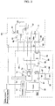
- FIG. 2 is a schematic configuration diagram illustrating a cogeneration system according to an exemplary embodiment of the present invention.
- the cogeneration system includes an engine 50, which operates, using fossil fuel such as natural gas or petroleum gas, a generator 52 to generate electricity, using a driving force of the engine 50, an exhaust gas heat exchanger 72 arranged at an exhaust conduit 54 to recover heat of exhaust gas discharged from the engine 50, a cooling water heat exchanger 82 to recover heat of cooling water of the engine 50, and a radiator 88 to radiate the cooling water heat.
- an engine 50 which operates, using fossil fuel such as natural gas or petroleum gas
- a generator 52 to generate electricity, using a driving force of the engine 50
- an exhaust gas heat exchanger 72 arranged at an exhaust conduit 54 to recover heat of exhaust gas discharged from the engine 50
- a cooling water heat exchanger 82 to recover heat of cooling water of the engine 50
- a radiator 88 to radiate the cooling water heat.
- the cogeneration system also includes a cooling/heating unit 60, which uses a heat pump type refrigerant cycle using waste heat generated from the engine 50.
- the cooling/heating unit 60 includes at least one compressor 61, a four-way valve 62, an outdoor heat exchanger 63, a fan 63a, an expansion device 64, and an indoor heat exchanger 65, as in a general heat pump type cooling/heating unit, which can be used as both a cooling unit and a heating unit in accordance with reversal of a refrigerant flow in a refrigerant cycle of the cooling/heating unit.
- the cogeneration system further includes a discharge-side refrigerant over-heater 70 to supply the heat of the exhaust gas discharged from the engine 50 to a discharge side of the compressor 61 included in the cooling/heating unit 60, and a cooling water heat supplier 80 to supply the heat of the cooling water used to cool the engine 50 to a suction side of the compressor 61 and to pre-heat air passing through the outdoor heat exchanger 63.
- a discharge-side refrigerant over-heater 70 to supply the heat of the exhaust gas discharged from the engine 50 to a discharge side of the compressor 61 included in the cooling/heating unit 60
- a cooling water heat supplier 80 to supply the heat of the cooling water used to cool the engine 50 to a suction side of the compressor 61 and to pre-heat air passing through the outdoor heat exchanger 63.
- the discharge-side refrigerant over-heater 70 includes the first exhaust gas heat exchanger 72, which is arranged at the exhaust conduit 54 to perform heat exchange with the exhaust gas passing through the exhaust conduit 54.
- the discharge-side refrigerant over-heater 70 also includes a discharge-side over-heating heat exchanger 74 to perform heat exchange between a line 73 to receive the heat recovered by the first exhaust gas heat exchanger 72 and a discharge-side refrigerant line 67 of the compressor 61.
- a refrigerant bypass line 69 is branched from the discharge-side refrigerant line 67 of the compressor 61. Valves 69a are also arranged in the discharge-side refrigerant line 67 to change a refrigerant path between the discharge-side refrigerant line 67 and the refrigerant bypass line 69.
- the refrigerant bypass line 69 and valves 69a serve to cause the refrigerant in the discharge-side refrigerant line 67 to directly flow toward the four-way valve 62 without passing through the discharge-side over-heating heat exchanger 74.
- the cooling water heat supplier 80 includes a suction-side over-heating heat exchanger 84 to perform heat exchange between a suction-side refrigerant line 66 of the compressor 61 and lines 81 and 83 to transfer the cooling water heat of the engine 50, and a pre-heating heat exchanger 89 arranged at an air flow zone of the outdoor heat exchanger 63 to receive the cooling water heat of the engine 50, and thus, to pre-heat outdoor air.
- the cooling water heat exchanger 82 which is connected to the engine 50 via the cooling water line 81 to recover the cooling water heat of the engine 50, is also included in the cooling water heat supplier 80.
- the suction-side over-heating heat exchanger 84 and pre-heating heat exchanger 89 receive the cooling water heat from the cooling water heat exchanger 82.
- the suction-side over-heating heat exchanger 84 primarily receives the cooling water heat through the heat transfer line 83, which extends through the cooling water heat exchanger 82, and the pre-heating heat exchanger 89 secondarily receives the cooling water heat through the heat transfer line 83.
- a cooling water heat radiating unit 85 is arranged at the cooling water line 81, which extends from the engine 50 to the cooling water heat exchanger 82, to radiate the heat of the cooling water.
- the cooling water heat radiating unit 85 includes a radiating line 87 branched from the cooling water line 81, a valve 86 to bypass the cooling water in the cooling water line 81 through the radiating line 87, and a radiator 88 arranged at the radiating line 87.
- the radiator 88 may be connected to other systems to use the waste heat of the cooling water, as in the above-described case in which the heat of the exhaust gas is used to heat water or to supply hot water.
- a refrigerant bypass line 68 is branched from the suction-side refrigerant line 66 of the compressor 61. Valves 68a are also arranged in the suction-side refrigerant line 66 to change a refrigerant path between the suction-side refrigerant line 66 and the refrigerant bypass line 68.
- the refrigerant bypass line 68 and valves 68a serve to cause the refrigerant in the suction-side refrigerant line 66 to flow without passing through the suction-side over-heating heat exchanger 84.
- reference character P designates pumps, each serving to force the heat transfer medium to flow through an associated line.
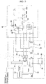
- FIG. 3 is a schematic configuration diagram illustrating a cogeneration system according to another exemplary embodiment of the present invention in which a plurality of indoor heat exchangers are used.
- a plurality of indoor heat exchangers 65A, 65B, and 65C are arranged in serial or parallel in a single cooling/heating unit 60 to cool/heat a plurality of confined spaces, respectively.
- Constituent elements of the configuration of FIG. 3 corresponding to those of FIG. 2 are designated by the same reference numerals, respectively, and no description thereof will be given.
- constituent elements of the configuration of FIG. 4, which will be described hereinafter, corresponding to those of FIG. 2 are designated by the same reference numerals, respectively, and no description thereof will be given.
- FIG. 4 is a schematic configuration diagram illustrating a cogeneration system according to another exemplary embodiment of the present invention in which a plurality of cooling/heating units are used.
- distributors 90, 95, and 96 are arranged at a suction-side refrigerant line 66, a discharge-side refrigerant line 67, and a heat transfer line 83, respectively, to distribute heat to a plurality of cooling/heating units 60A, 60B, and 60C.
- the above-described heat exchangers may have various heat transfer configurations, for example, a heat transfer configuration in which heat transfer is carried out through a thermal conductor, or a heat transfer configuration in which heat transfer is carried out through a fluid present in a heat exchanger, in accordance with the given design condition or the given requirement.
- Electricity which is generated by a driving force from the engine 50, may be used to operate the compressor 61 of the cooling/heating unit 50 and diverse controllers.
- a refrigerant flows through the compressor 61, four-way valve 62, indoor heat exchanger 65, expansion device 64, and outdoor heat exchanger 63, in this order, to perform a heating operation.
- the refrigerant sucked toward the compressor 61 through the suction-side refrigerant line 66 is primarily pre-heated by the heat of the cooling water of the engine 50 while passing through the suction-side over-heating heat exchanger 84, and is then introduced into the compressor 61.
- the refrigerant discharged from the compressor 61 through the discharge-side refrigerant line 67 is secondarily heated by the discharge-side over-heating heat exchanger 74 while passing through the discharge-side over-heating heat exchanger 74, and is fed toward the indoor heat exchanger 65.
- the refrigerant Since the refrigerant is pre-heated by the waste heat of the engine 50 at both the suction and discharge sides of the compressor 61, as described above, the refrigerant passes through the indoor heat exchanger 65 serving as a condenser, under the condition in which the temperature of the refrigerant is increased to a desired level. Accordingly, it is possible to provide heat of a higher temperature to a confined space, and thus, to achieve an enhancement in heating performance.
- the suction side of the compressor 61 uses cooling water heat and secondary exhaust gas heat, which are maintained at a temperature relatively lower than that of the exhaust gas heat used at the discharge side of the compressor 61. Accordingly, it is possible to prevent the refrigerant from being excessively pre-heated, and thus, from being excessively increased in temperature while passing through the compressor 61.
- the refrigerant absorbs heat of a high temperature while passing through the discharge-side over-heating heat exchanger 74, which is maintained at a relatively high temperature, and then passes through the indoor heat exchanger 65.
- the compressor 61 form being damaged due to an excessively high increase in pressure.
- suction-side refrigerant line 66 is indirectly connected to the cooling water heat exchanger 82 such that the suction-side refrigerant line 66 performs heat exchange with the cooling water heat exchanger 82 via the suction-side over-heating heat exchanger 84, it is possible to prevent the refrigerant from being over-heated, and thus, rapidly degraded.
- the valves 68a of the suction-side refrigerant line 66, the valves 69a of the discharge-side refrigerant line 67, and the valve 86 of the cooling water line 81 are selectively operated to change fluid paths associated with the exhaust gas heat and cooling water heat, respectively.
- the refrigerant in the cooling/heating unit 60 flows through the bypass lines 68 and 69, so that the refrigerant is circulated through the refrigerant cycle under the condition in which the temperature of the refrigerant is maintained at a normal level.
- the cooling operation is normally carried out.
- the pre-heating heat exchanger 89 which is arranged upstream from the outdoor heat exchanger 63, receives the cooling water heat recovered by the cooling water heat exchanger 82, and pre-heats the outdoor heat exchanger 63 serving as an evaporator during the heating operation of the cooling/heating unit 60. Accordingly, it is possible to prevent the heat performance of the cooling/heating unit 60 from being degraded under the condition in which the ambient temperature is considerably low.
- the cooling water heat of the engine is supplied to the suction side of the compressor, and the exhaust gas heat of the engine is supplied to the discharge side of the compressor. Accordingly, it is possible to maximize absorption of the waste heat of the engine while preventing compressor malfunction, and thus, to increase the refrigerant condensing temperature of the indoor heat exchanger. Thus, an enhancement in heating performance is achieved.
- the cogeneration system of the present invention is configured so that the cooling water heat of the engine is used to pre-heat the outdoor heat exchanger. Accordingly, it is possible to prevent a degradation in heating performance when the ambient temperature is low, and thus, to achieve an enhancement in heating performance.
Landscapes
- Engineering & Computer Science (AREA)
- Mechanical Engineering (AREA)
- General Engineering & Computer Science (AREA)
- Physics & Mathematics (AREA)
- Thermal Sciences (AREA)
- Chemical & Material Sciences (AREA)
- Combustion & Propulsion (AREA)
- Heat-Pump Type And Storage Water Heaters (AREA)
- Compression-Type Refrigeration Machines With Reversible Cycles (AREA)
Abstract
Description
- The present invention relates to a cogeneration system in which both the electricity and waste heat generated from an engine are used, and, more particularly, to a cogeneration system in which waste heat generated from an engine is supplied to suction and discharge sides of a compressor and to an outdoor heat exchanger to achieve an enhancement in heating performance.
- In general, cogeneration systems are adapted to generate both electricity and heat from a single energy source.
- Such a cogeneration system can recover heat of exhaust gas or waste heat of cooling water generated from an engine or turbine during an electricity generation operation, so that the cogeneration system can achieve an increase in energy efficiency of 70 to 80% over other systems. By virtue of such an advantage, the cogeneration system has recently been highlighted as an electricity and heat supply source for buildings. In particular, the cogeneration system exhibits highly-efficient energy utilization in that the recovered waste heat is mainly used to heat/cool a confined space and to heat water.
- FIG. 1 is a schematic configuration diagram illustrating a conventional cogeneration system used in a heating/cooling apparatus.
- As shown in FIG. 1, the conventional cogeneration system includes a gas engine 1, and a generator 3, which is driven by a driving force outputted from the gas engine 1, to generate electricity. The electricity generated from the generator 3 is used in a variety of devices including a cooling/
heating unit 20, illumination devices, and other electrical products. - In the cogeneration system, waste heat generated from the gas engine 1, that is, heat of cooling water generated when the cooling water cools the gas engine 1, and heat of exhaust gas generated from the gas engine 1, is used during a heating operation of the cooling/
heating unit 20. - Here, the cooling/
heating unit 20 is of a heat pump type so that the cooling/heating unit 20 not only can be used as a cooling unit, but also can be used as a heating unit in a state in which the refrigerant flow direction in the refrigerant cycle is reversed. As in a general heat pump type configuration, the cooling/heating unit 20 includes acompressor 21, a four-way valve 23, anoutdoor heat exchanger 25, anoutdoor fan 26, anexpansion device 27, and anindoor heat exchanger 29. - In particular, an air pre-heating
heat exchanger 30 is arranged at the side of theoutdoor heat exchanger 25 to preheat air passing around theoutdoor heat exchanger 25 during a heating operation of the cooling/heating unit 20, using the waste heat of the gas engine 1. - In order to supply the waste heat to the cooling/
heating unit 20, the cogeneration system also includes a cooling water heat exchanger 5 to recover the heat of the cooling water used to cool the gas engine 1, and an exhaustgas heat exchanger 9 arranged at anexhaust conduit 7 to recover the heat of the exhaust gas. - The cooling water heat exchanger 5 and exhaust
gas heat exchanger 9 are connected to the air pre-heatingheat exchanger 30 of the cooling/heating unit 20 by aheat transfer line 11, through which a heat transfer medium flows, so as to supply waste heat to the air pre-heatingheat exchanger 30 during the heating operation of the cooling/heating unit 20. Thus, the' cogeneration system recovers engine heat and exhaust gas heat, pre-heats outdoor air through the air pre-heatingheat exchanger 30, using the recovered heat, and causes the pre-heated air to perform heat exchange with theoutdoor heat exchanger 25, thereby preventing a degradation in the heating performance of the cooling/heating unit 20, which may occur when the temperature of the outdoor air is low. - When the cooling/
heating unit 20 operates in a cooling mode, the flow path of the heat transfer medium is changed to communicate with aradiating line 13, which is connected to theheat transfer line 11, because it is unnecessary to supply waste heat. In this case, the waste heat is discharged to the atmosphere through aradiator 17, which includes aheat exchanger 15 and aradiator fan 16, or is supplied to and used in a water heater, a hot water supplier, or other systems. - In FIG. 1, reference character P designates pumps, each serving to force the heat transfer medium to flow through an associated portion of the
heat transfer line 11, and reference character V designates valves, each serving to switch the flow path of the heat transfer medium between theheat transfer line 11 and theradiating line 13. - However, since the waste heat generated from the gas engine 1 is used only to pre-heat the
outdoor heat exchanger 25 through the air pre-heatingheat exchanger 30, the conventional cogeneration system has a limitation in enhancing the heating performance during the heating operation. - The present invention has been made in view of the above-mentioned problem, and it is an object of the invention to provide a cogeneration system in which waste heat generated from an engine is supplied not only to suction and discharge sides of a compressor, but also to an outdoor heat exchanger to pre-heat a refrigerant passing through the outdoor heat exchanger, thereby achieving an enhancement in heating performance during a heating operation.
- In accordance with one aspect, the present invention provides a cogeneration system comprising: an engine, which drives a generator to generate electricity; a cooling/heating unit, which comprises at least one compressor, a four-way valve, an outdoor heat exchanger, an expansion device, and an indoor heat exchanger, to establish a heat pump type refrigerant cycle; a cooling water heat supplier to supply heat of cooling water used to cool the engine to a suction side of the compressor of the cooling/heating unit and to pre-heat air passing through the outdoor heat exchanger; and a discharge-side refrigerant over-heater to supply heat of exhaust gas discharged from the engine to a discharge side of the compressor.
- The cooling water heat supplier may comprise a suction-side over-heating heat exchanger to perform heat exchange between a suction-side refrigerant line of the compressor and a cooling water line to transfer the cooling water heat of the engine, and a pre-heating heat exchanger arranged at an air flow zone of the outdoor heat exchanger to receive the cooling water heat of the engine, and thus, to pre-heat outdoor air.
- The cooling water heat supplier may further comprise a cooling water heat exchanger connected to the engine via the cooling water line to recover the cooling water heat of the engine. The suction-side over-heating heat exchanger and the pre-heating heat exchanger may receive the cooling water heat from the cooling water heat exchanger.
- The cogeneration system may further comprise a cooling water heat radiating unit arranged at the cooling water line, which extends from the engine to the cooling water heat exchanger, to radiate the heat of the cooling water.
- The cooling water heat supplier may primarily receive the cooling water heat through the suction-side over-heating heat exchanger, and may secondarily receive the cooling water heat through the pre-heating heat exchanger.
- The cooling water heat supplier may further comprise a bypass line branched from the suction-side refrigerant line of the compressor, and a valve arranged in the suction-side refrigerant line to change a refrigerant path between the suction-side refrigerant line and the bypass line, whereby the refrigerant bypass line and the valve function to cause a refrigerant in the suction-side refrigerant line to flow without passing through the suction-side over-heating heat exchanger.
- The discharge-side refrigerant over-heater may comprise an exhaust gas heat exchanger arranged at an exhaust conduit of the engine to recover the exhaust gas heat, and a discharge-side over-heating heat exchanger to perform heat exchange between a line to receive the heat recovered by the exhaust gas heat exchanger and a discharge-side refrigerant line of the compressor.
- The discharge-side refrigerant over-heater may further comprise a bypass line branched from the discharge-side refrigerant line of the compressor, and a valve arranged in the discharge-side refrigerant line to change a refrigerant path between the discharge-side refrigerant line and the bypass line, whereby the refrigerant bypass line and the valve function to cause a refrigerant in the discharge-side refrigerant line to flow without passing through the discharge-side over-heating heat exchanger.
- In accordance with another aspect, the present invention provides a cogeneration system comprising: an engine, which drives a generator to generate electricity; a cooling/heating unit, which comprises at least one compressor, a four-way valve , an outdoor heat exchanger, an expansion device, and an indoor heat exchanger, to establish a heat pump type refrigerant cycle; and a cooling water heat supplier to primarily supply heat of cooling water used to cool the engine to a suction side of the compressor of the cooling/heating unit, and to secondarily supply the cooling water heat to the outdoor heat exchanger, and thus, to pre-heat air passing through the outdoor heat exchanger.
- In the cogeneration system of the present invention, the cooling water heat of the engine is supplied to the suction side of the compressor, and the exhaust gas heat of the engine is supplied to the discharge side of the compressor. Accordingly, it is possible to maximize absorption of the waste heat of the engine while preventing compressor malfunction, and thus, to increase the refrigerant condensing temperature of the indoor heat exchanger. Thus, an enhancement in heating performance is achieved.
- Also, the cogeneration system of the present invention is configured so that the cooling water heat of the engine is used to pre-heat the outdoor heat exchanger. Accordingly, it is possible to prevent a degradation in heating performance when the ambient temperature is low, and thus, to achieve an enhancement in heating performance.
- The above objects, and other features and advantages of the present invention will become more apparent after reading the following detailed description when taken in conjunction with the drawings, in which:
- FIG. 1 is a schematic configuration diagram illustrating a conventional cogeneration system;
- FIG. 2 is a schematic configuration diagram illustrating a cogeneration system according to an exemplary embodiment of the present invention;
- FIG. 3 is a schematic configuration diagram illustrating a cogeneration system according to another exemplary embodiment of the present invention in which a plurality of indoor heat exchangers are used; and
- FIG. 4 is a schematic configuration diagram illustrating a cogeneration system according to another exemplary embodiment of the present invention in which a plurality of cooling/heating units are used.
- Hereinafter, exemplary embodiments of a cogeneration system according to the present invention will be described with reference to the annexed drawings.
- FIG. 2 is a schematic configuration diagram illustrating a cogeneration system according to an exemplary embodiment of the present invention.
- As shown in FIG. 2, the cogeneration system includes an
engine 50, which operates, using fossil fuel such as natural gas or petroleum gas, agenerator 52 to generate electricity, using a driving force of theengine 50, an exhaustgas heat exchanger 72 arranged at anexhaust conduit 54 to recover heat of exhaust gas discharged from theengine 50, a coolingwater heat exchanger 82 to recover heat of cooling water of theengine 50, and aradiator 88 to radiate the cooling water heat. - The cogeneration system also includes a cooling/
heating unit 60, which uses a heat pump type refrigerant cycle using waste heat generated from theengine 50. The cooling/heating unit 60 includes at least onecompressor 61, a four-way valve 62, anoutdoor heat exchanger 63, afan 63a, anexpansion device 64, and anindoor heat exchanger 65, as in a general heat pump type cooling/heating unit, which can be used as both a cooling unit and a heating unit in accordance with reversal of a refrigerant flow in a refrigerant cycle of the cooling/heating unit. - In particular, the cogeneration system further includes a discharge-side refrigerant over-heater 70 to supply the heat of the exhaust gas discharged from the
engine 50 to a discharge side of thecompressor 61 included in the cooling/heating unit 60, and a coolingwater heat supplier 80 to supply the heat of the cooling water used to cool theengine 50 to a suction side of thecompressor 61 and to pre-heat air passing through theoutdoor heat exchanger 63. - The discharge-side refrigerant over-heater 70 includes the first exhaust
gas heat exchanger 72, which is arranged at theexhaust conduit 54 to perform heat exchange with the exhaust gas passing through theexhaust conduit 54. The discharge-side refrigerant over-heater 70 also includes a discharge-side over-heatingheat exchanger 74 to perform heat exchange between aline 73 to receive the heat recovered by the first exhaustgas heat exchanger 72 and a discharge-side refrigerant line 67 of thecompressor 61. - A
refrigerant bypass line 69 is branched from the discharge-side refrigerant line 67 of thecompressor 61. Valves 69a are also arranged in the discharge-side refrigerant line 67 to change a refrigerant path between the discharge-side refrigerant line 67 and therefrigerant bypass line 69. Therefrigerant bypass line 69 andvalves 69a serve to cause the refrigerant in the discharge-side refrigerant line 67 to directly flow toward the four-way valve 62 without passing through the discharge-side over-heatingheat exchanger 74. - The cooling
water heat supplier 80 includes a suction-side over-heatingheat exchanger 84 to perform heat exchange between a suction-side refrigerant line 66 of thecompressor 61 andlines engine 50, and apre-heating heat exchanger 89 arranged at an air flow zone of theoutdoor heat exchanger 63 to receive the cooling water heat of theengine 50, and thus, to pre-heat outdoor air. - The cooling
water heat exchanger 82, which is connected to theengine 50 via thecooling water line 81 to recover the cooling water heat of theengine 50, is also included in the coolingwater heat supplier 80. The suction-side over-heatingheat exchanger 84 and pre-heatingheat exchanger 89 receive the cooling water heat from the coolingwater heat exchanger 82. - That is, in the cooling
water heat supplier 80, the suction-side over-heatingheat exchanger 84 primarily receives the cooling water heat through theheat transfer line 83, which extends through the coolingwater heat exchanger 82, and thepre-heating heat exchanger 89 secondarily receives the cooling water heat through theheat transfer line 83. - A cooling water
heat radiating unit 85 is arranged at thecooling water line 81, which extends from theengine 50 to the coolingwater heat exchanger 82, to radiate the heat of the cooling water. - In order to radiate the heat of the cooling water to the atmosphere, the cooling water
heat radiating unit 85 includes aradiating line 87 branched from thecooling water line 81, avalve 86 to bypass the cooling water in thecooling water line 81 through theradiating line 87, and aradiator 88 arranged at theradiating line 87. Theradiator 88 may be connected to other systems to use the waste heat of the cooling water, as in the above-described case in which the heat of the exhaust gas is used to heat water or to supply hot water. - A
refrigerant bypass line 68 is branched from the suction-side refrigerant line 66 of thecompressor 61. Valves 68a are also arranged in the suction-side refrigerant line 66 to change a refrigerant path between the suction-side refrigerant line 66 and therefrigerant bypass line 68. Therefrigerant bypass line 68 andvalves 68a serve to cause the refrigerant in the suction-siderefrigerant line 66 to flow without passing through the suction-sideover-heating heat exchanger 84. - In FIG. 2, reference character P designates pumps, each serving to force the heat transfer medium to flow through an associated line.
- On the other hand, FIG. 3 is a schematic configuration diagram illustrating a cogeneration system according to another exemplary embodiment of the present invention in which a plurality of indoor heat exchangers are used. In this case, a plurality of indoor heat exchangers 65A, 65B, and 65C are arranged in serial or parallel in a single cooling/
heating unit 60 to cool/heat a plurality of confined spaces, respectively. - Constituent elements of the configuration of FIG. 3 corresponding to those of FIG. 2 are designated by the same reference numerals, respectively, and no description thereof will be given. Similarly, constituent elements of the configuration of FIG. 4, which will be described hereinafter, corresponding to those of FIG. 2 are designated by the same reference numerals, respectively, and no description thereof will be given.
- FIG. 4 is a schematic configuration diagram illustrating a cogeneration system according to another exemplary embodiment of the present invention in which a plurality of cooling/heating units are used. In this case,
distributors 90, 95, and 96 are arranged at a suction-siderefrigerant line 66, a discharge-side refrigerant line 67, and aheat transfer line 83, respectively, to distribute heat to a plurality of cooling/heating units - Meanwhile, the above-described heat exchangers may have various heat transfer configurations, for example, a heat transfer configuration in which heat transfer is carried out through a thermal conductor, or a heat transfer configuration in which heat transfer is carried out through a fluid present in a heat exchanger, in accordance with the given design condition or the given requirement.
- Hereinafter, operation of the cogeneration system according to the present invention will be described.
- Electricity, which is generated by a driving force from the
engine 50, may be used to operate thecompressor 61 of the cooling/heating unit 50 and diverse controllers. - During a heating operation of the cooling/
heating unit 60, a refrigerant flows through thecompressor 61, four-way valve 62,indoor heat exchanger 65,expansion device 64, andoutdoor heat exchanger 63, in this order, to perform a heating operation. - In this case, the refrigerant sucked toward the
compressor 61 through the suction-siderefrigerant line 66 is primarily pre-heated by the heat of the cooling water of theengine 50 while passing through the suction-sideover-heating heat exchanger 84, and is then introduced into thecompressor 61. - The refrigerant discharged from the
compressor 61 through the discharge-side refrigerant line 67 is secondarily heated by the discharge-sideover-heating heat exchanger 74 while passing through the discharge-sideover-heating heat exchanger 74, and is fed toward theindoor heat exchanger 65. - Since the refrigerant is pre-heated by the waste heat of the
engine 50 at both the suction and discharge sides of thecompressor 61, as described above, the refrigerant passes through theindoor heat exchanger 65 serving as a condenser, under the condition in which the temperature of the refrigerant is increased to a desired level. Accordingly, it is possible to provide heat of a higher temperature to a confined space, and thus, to achieve an enhancement in heating performance. - In particular, the suction side of the
compressor 61 uses cooling water heat and secondary exhaust gas heat, which are maintained at a temperature relatively lower than that of the exhaust gas heat used at the discharge side of thecompressor 61. Accordingly, it is possible to prevent the refrigerant from being excessively pre-heated, and thus, from being excessively increased in temperature while passing through thecompressor 61. At the discharge side of thecompressor 61, however, the refrigerant absorbs heat of a high temperature while passing through the discharge-sideover-heating heat exchanger 74, which is maintained at a relatively high temperature, and then passes through theindoor heat exchanger 65. Thus, it is possible to prevent thecompressor 61 form being damaged due to an excessively high increase in pressure. - Also, since the suction-side
refrigerant line 66 is indirectly connected to the coolingwater heat exchanger 82 such that the suction-siderefrigerant line 66 performs heat exchange with the coolingwater heat exchanger 82 via the suction-sideover-heating heat exchanger 84, it is possible to prevent the refrigerant from being over-heated, and thus, rapidly degraded. - When the cooling/
heating unit 60 operates in a cooling mode or stops the cooling/heating operation thereof, it is necessary to prevent heat of exhaust gas and heat of cooling water generated from theengine 50 from being supplied to the cooling/heating unit 60. In this case, accordingly, thevalves 68a of the suction-siderefrigerant line 66, thevalves 69a of the discharge-side refrigerant line 67, and thevalve 86 of the coolingwater line 81 are selectively operated to change fluid paths associated with the exhaust gas heat and cooling water heat, respectively. - As a result, the refrigerant in the cooling/
heating unit 60 flows through thebypass lines - Meanwhile, the
pre-heating heat exchanger 89, which is arranged upstream from theoutdoor heat exchanger 63, receives the cooling water heat recovered by the coolingwater heat exchanger 82, and pre-heats theoutdoor heat exchanger 63 serving as an evaporator during the heating operation of the cooling/heating unit 60. Accordingly, it is possible to prevent the heat performance of the cooling/heating unit 60 from being degraded under the condition in which the ambient temperature is considerably low. - As apparent from the above description, in the cogeneration system of the present invention, the cooling water heat of the engine is supplied to the suction side of the compressor, and the exhaust gas heat of the engine is supplied to the discharge side of the compressor. Accordingly, it is possible to maximize absorption of the waste heat of the engine while preventing compressor malfunction, and thus, to increase the refrigerant condensing temperature of the indoor heat exchanger. Thus, an enhancement in heating performance is achieved.
- Also, the cogeneration system of the present invention is configured so that the cooling water heat of the engine is used to pre-heat the outdoor heat exchanger. Accordingly, it is possible to prevent a degradation in heating performance when the ambient temperature is low, and thus, to achieve an enhancement in heating performance.
- Although the preferred embodiments of the invention have been disclosed for illustrative purposes, those skilled in the art will appreciate that various modifications, additions and substitutions are possible, without departing from the scope and spirit of the invention as disclosed in the accompanying claims.
Claims (10)
- A cogeneration system comprising:an engine (50), which drives a generator (52) to generate electricity;a cooling/heating unit (60), which comprises at least one compressor (61), a four-way valve (62), an outdoor heat exchanger (63), an expansion device (64), and an indoor heat exchanger (65), to establish a heat pump type refrigerant cycle;a cooling water heat supplier (80) to supply heat of cooling water used to cool the engine (50) to a suction side of the compressor (61) of the cooling/heating unit (60) and to pre-heat air passing through the outdoor heat exchanger (63); anda discharge-side refrigerant over-heater (70) to supply heat of exhaust gas discharged from the engine (50) to a discharge side of the compressor (61).
- The cogeneration system according to claim 1, wherein the cooling water heat supplier (80) comprises:a suction-side over-heating heat exchanger (84) to perform heat exchange between a suction-side refrigerant line (66) of the compressor (61) and a cooling water line (81, 83) to transfer the cooling water heat of the engine (50); anda pre-heating heat exchanger (89) arranged at an air flow zone of the outdoor heat exchanger (63) to receive the cooling water heat of the engine (50), and thus, to pre-heat outdoor air.
- The cogeneration system according to claim 2, wherein:the cooling water heat supplier (80) further comprises a cooling water heat exchanger (82) connected to the engine (50) via the cooling water line (81) to recover the cooling water heat of the engine (50); andthe suction-side over-heating heat exchanger (84) and the pre-heating heat exchanger (89) receive the cooling water heat from the cooling water heat exchanger (82).
- The cogeneration system according to claim 3, further comprising:a cooling water heat radiating unit (85) arranged at the cooling water line (81), which extends from the engine (50) to the cooling water heat exchanger (82), to radiate the heat of the cooling water.
- The cogeneration system according to claim 2, wherein the cooling water heat supplier (80) primarily receives the cooling water heat through the suction-side over-heating heat exchanger (84), and secondarily receives the cooling water heat through the pre-heating heat exchanger (89).
- The cogeneration system according to claim 2, wherein the cooling water heat supplier (80) further comprises:a bypass line (68) branched from the suction-side refrigerant line (66) of the compressor (61); anda valve (68a) arranged in the suction-side refrigerant line (66) to change a refrigerant path between the suction-side refrigerant line (66) and the bypass line (68),whereby the refrigerant bypass line (68) and the valve (68a) function to cause a refrigerant in the suction-side refrigerant line (66) to flow without passing through the suction-side over-heating heat exchanger (84).
- The cogeneration system according to claim 1, wherein the discharge-side refrigerant over-heater (70) comprises:an exhaust gas heat exchanger (72) arranged at an exhaust conduit (54) of the engine (50) to recover the exhaust gas heat; anda discharge-side over-heating heat exchanger (74) to perform heat exchange between a line (73) to receive the heat recovered by the exhaust gas heat exchanger (72) and a discharge-side refrigerant line (67) of the compressor (61).
- The cogeneration system according to claim 7, wherein the discharge-side refrigerant over-heater (70) further comprises:a bypass line (69) branched from the discharge-side refrigerant line (67) of the compressor (61); anda valve (69a) arranged in the discharge-side refrigerant line (67) to change a refrigerant path between the discharge-side refrigerant line (67) and the bypass line (69),whereby the refrigerant bypass line (69) and the valve (69a) function to cause a refrigerant in the discharge-side refrigerant line (67) to flow without passing through the discharge-side over-heating heat exchanger (74).
- A cogeneration system comprising:an engine (50), which drives a generator (52) to generate electricity;a cooling/heating unit (60), which comprises at least one compressor (61), a four-way valve (62), an outdoor heat exchanger (63), an expansion device (64), and an indoor heat exchanger (65), to establish a heat pump type refrigerant cycle; anda cooling water heat supplier (80) to primarily supply heat of cooling water used to cool the engine (50) to a suction side of the compressor (61) of the cooling/heating unit (60), and to secondarily supply the cooling water heat to the outdoor heat exchanger (63), and thus, to pre-heat air passing through the outdoor heat exchanger (63).
- The cogeneration system according to claim 9, wherein the cooling water heat supplier (80) comprises:a suction-side over-heating heat exchanger (84) to perform heat exchange between a suction-side refrigerant line (66) of the compressor (61) and a cooling water line (81, 83) to transfer the cooling water heat of the engine (50); anda pre-heating heat exchanger (89) arranged at an air flow zone of the outdoor heat exchanger (63) to receive the cooling water heat of the engine (50), and thus, to pre-heat outdoor air.
Applications Claiming Priority (1)
| Application Number | Priority Date | Filing Date | Title |
|---|---|---|---|
| KR1020040064809A KR100579574B1 (en) | 2004-08-17 | 2004-08-17 | Cogeneration System |
Publications (2)
| Publication Number | Publication Date |
|---|---|
| EP1628092A2 true EP1628092A2 (en) | 2006-02-22 |
| EP1628092A3 EP1628092A3 (en) | 2011-06-15 |
Family
ID=36080347
Family Applications (1)
| Application Number | Title | Priority Date | Filing Date |
|---|---|---|---|
| EP05001040A Withdrawn EP1628092A3 (en) | 2004-08-17 | 2005-01-19 | Air conditioning system combined with an electricity generating system |
Country Status (4)
| Country | Link |
|---|---|
| US (1) | US20060037352A1 (en) |
| EP (1) | EP1628092A3 (en) |
| KR (1) | KR100579574B1 (en) |
| CN (1) | CN100338413C (en) |
Cited By (4)
| Publication number | Priority date | Publication date | Assignee | Title |
|---|---|---|---|---|
| EP1882891A3 (en) * | 2006-07-27 | 2008-06-25 | LG Electronics Inc. | CO-Generation |
| WO2014022508A1 (en) * | 2012-08-02 | 2014-02-06 | Trane International Inc. | Combined heat and power heat pump |
| EP2629031A3 (en) * | 2012-02-14 | 2018-07-11 | Lg Electronics Inc. | Gas heat pump system |
| US20180372333A1 (en) * | 2017-06-27 | 2018-12-27 | Imby Energy, Inc. | Cogeneration systems and methods for generating heating and electricity |
Families Citing this family (18)
| Publication number | Priority date | Publication date | Assignee | Title |
|---|---|---|---|---|
| US6598226B1 (en) * | 1999-11-12 | 2003-07-22 | Zenith Electronics Corporation | Apparatus and method for providing, retrieving, and using data guide information supplied in a digital vestigial sideband signal |
| KR20060112844A (en) * | 2005-04-28 | 2006-11-02 | 엘지전자 주식회사 | Cogeneration System |
| US7503184B2 (en) * | 2006-08-11 | 2009-03-17 | Southwest Gas Corporation | Gas engine driven heat pump system with integrated heat recovery and energy saving subsystems |
| KR100830462B1 (en) * | 2006-12-22 | 2008-05-20 | 엘지전자 주식회사 | Air conditioning system |
| KR101581466B1 (en) * | 2008-08-27 | 2015-12-31 | 엘지전자 주식회사 | Air conditioning system |
| JP5375349B2 (en) * | 2009-06-10 | 2013-12-25 | ダイキン工業株式会社 | Transportation refrigeration equipment |
| FR2948990A1 (en) * | 2009-08-04 | 2011-02-11 | Mobile Comfort Holding | MODULAR MULTI-ENERGY THERMODYNAMIC DEVICE |
| CN101892924B (en) * | 2010-07-16 | 2012-03-28 | 华南理工大学 | Vehicle exhaust waste heat generating system |
| CN101950964B (en) * | 2010-08-24 | 2011-09-21 | 西安交通大学 | System containing cogeneration unit and pure condensing steam thermal power unit as well as scheduling method |
| CN102510106B (en) * | 2011-10-23 | 2013-11-06 | 重庆市电力公司电力科学研究院 | Combined heat and power dispatching system comprising steam-extracting steam-condensing type cogeneration unit and dispatching method thereof |
| US9562715B2 (en) * | 2012-03-21 | 2017-02-07 | Thermo King Corporation | Power regulation system for a mobile environment-controlled unit and method of controlling the same |
| US9228760B2 (en) | 2012-04-27 | 2016-01-05 | Mac, Inc. | Flameless heating system |
| US9115603B2 (en) * | 2012-07-24 | 2015-08-25 | Electratherm, Inc. | Multiple organic Rankine cycle system and method |
| US10036347B1 (en) * | 2013-07-19 | 2018-07-31 | Raymond C. Sherry | Standby energy generating system |
| EP3150935B1 (en) * | 2014-05-30 | 2019-03-06 | Mitsubishi Electric Corporation | Air conditioner |
| CN105276856B (en) * | 2014-06-13 | 2019-05-28 | 松下知识产权经营株式会社 | Gas heat pump air conditioning system |
| KR101698259B1 (en) * | 2015-01-12 | 2017-01-19 | 엘지전자 주식회사 | Air conditioner and method for controlling the same |
| KR101698260B1 (en) * | 2015-01-12 | 2017-01-19 | 엘지전자 주식회사 | Air conditioner and method for controlling the same |
Citations (2)
| Publication number | Priority date | Publication date | Assignee | Title |
|---|---|---|---|---|
| JP2001280740A (en) | 2000-03-31 | 2001-10-10 | Mitsubishi Heavy Ind Ltd | Air conditioner |
| EP1288591A2 (en) | 2001-08-31 | 2003-03-05 | Mitsubishi Heavy Industries, Ltd. | Gas heat pump type air conditioning device, and combustion device for heating exhaust gas |
Family Cites Families (14)
| Publication number | Priority date | Publication date | Assignee | Title |
|---|---|---|---|---|
| US4697434A (en) * | 1985-10-17 | 1987-10-06 | Mitsubishi Denki Kabushiki Kaisha | Prime mover driven air-conditioning and hot-water supplying system |
| US4693089A (en) * | 1986-03-27 | 1987-09-15 | Phenix Heat Pump Systems, Inc. | Three function heat pump system |
| JPH01314829A (en) * | 1988-06-14 | 1989-12-20 | Mitsubishi Electric Corp | Space heater |
| US5729985A (en) * | 1994-12-28 | 1998-03-24 | Yamaha Hatsudoki Kabushiki Kaisha | Air conditioning apparatus and method for air conditioning |
| JPH08219585A (en) * | 1995-02-10 | 1996-08-30 | Mitsubishi Heavy Ind Ltd | Engine driven type air conditioning equipment |
| US5966952A (en) * | 1996-09-05 | 1999-10-19 | Yamaha Hatsudoki Kabushiki Kaisha | Heat pump system with balanced total heating-emitting and absorbing capacities and method for stable heat pumping operation |
| JP3576866B2 (en) * | 1999-05-10 | 2004-10-13 | 株式会社テージーケー | Refrigeration cycle with bypass line for vehicles |
| JP2001221531A (en) * | 2000-02-04 | 2001-08-17 | Mitsubishi Heavy Ind Ltd | Air conditioner |
| JP2001280739A (en) * | 2000-03-31 | 2001-10-10 | Mitsubishi Heavy Ind Ltd | Air conditioner |
| JP2001324240A (en) * | 2000-05-18 | 2001-11-22 | Sanyo Electric Co Ltd | Multi energy system |
| JP2002130743A (en) * | 2000-10-30 | 2002-05-09 | Mitsubishi Heavy Ind Ltd | Outdoor heat exchanger unit structure, outdoor unit and gas heat pump air conditioner |
| US6460360B2 (en) * | 2001-02-20 | 2002-10-08 | Sheng-Ming Hsieh | Power-generating and energy-saving system |
| EP1275913A3 (en) * | 2001-06-26 | 2003-08-13 | Mitsubishi Heavy Industries, Ltd. | Multiform gas heat pump type air conditioning system |
| JP4774171B2 (en) * | 2001-08-20 | 2011-09-14 | 社団法人エルピーガス協会 | Air conditioner |
-
2004
- 2004-08-17 KR KR1020040064809A patent/KR100579574B1/en not_active Expired - Fee Related
-
2005
- 2005-01-19 EP EP05001040A patent/EP1628092A3/en not_active Withdrawn
- 2005-02-01 US US11/046,752 patent/US20060037352A1/en not_active Abandoned
- 2005-02-06 CN CNB200510008238XA patent/CN100338413C/en not_active Expired - Fee Related
Patent Citations (2)
| Publication number | Priority date | Publication date | Assignee | Title |
|---|---|---|---|---|
| JP2001280740A (en) | 2000-03-31 | 2001-10-10 | Mitsubishi Heavy Ind Ltd | Air conditioner |
| EP1288591A2 (en) | 2001-08-31 | 2003-03-05 | Mitsubishi Heavy Industries, Ltd. | Gas heat pump type air conditioning device, and combustion device for heating exhaust gas |
Cited By (11)
| Publication number | Priority date | Publication date | Assignee | Title |
|---|---|---|---|---|
| EP1882891A3 (en) * | 2006-07-27 | 2008-06-25 | LG Electronics Inc. | CO-Generation |
| EP2629031A3 (en) * | 2012-02-14 | 2018-07-11 | Lg Electronics Inc. | Gas heat pump system |
| WO2014022508A1 (en) * | 2012-08-02 | 2014-02-06 | Trane International Inc. | Combined heat and power heat pump |
| CN104641188A (en) * | 2012-08-02 | 2015-05-20 | 特灵国际有限公司 | Combined thermoelectric heat pump |
| CN104641188B (en) * | 2012-08-02 | 2017-08-04 | 特灵国际有限公司 | Combined thermoelectric heat pump |
| US9759456B2 (en) | 2012-08-02 | 2017-09-12 | Trane International Inc. | Combined heat and power heat pump |
| US20180372333A1 (en) * | 2017-06-27 | 2018-12-27 | Imby Energy, Inc. | Cogeneration systems and methods for generating heating and electricity |
| US20180372337A1 (en) * | 2017-06-27 | 2018-12-27 | Imby Energy, Inc. | Cogeneration systems and methods for generating heating and electricity |
| US11041636B2 (en) * | 2017-06-27 | 2021-06-22 | Imby Energy, Inc. | Cogeneration systems and methods for generating heating and electricity |
| US11041637B2 (en) * | 2017-06-27 | 2021-06-22 | Imby Energy, Inc. | Cogeneration systems and methods for generating heating and electricity |
| US11041635B2 (en) * | 2017-06-27 | 2021-06-22 | Imby Energy, Inc. | Cogeneration systems and methods for generating heating and electricity |
Also Published As
| Publication number | Publication date |
|---|---|
| KR20060016390A (en) | 2006-02-22 |
| CN100338413C (en) | 2007-09-19 |
| KR100579574B1 (en) | 2006-05-15 |
| US20060037352A1 (en) | 2006-02-23 |
| EP1628092A3 (en) | 2011-06-15 |
| CN1737462A (en) | 2006-02-22 |
Similar Documents
| Publication | Publication Date | Title |
|---|---|---|
| EP1628092A2 (en) | Air conditioning system combined with an electricity generating system | |
| US7243505B2 (en) | Cogeneration system | |
| US7275382B2 (en) | Cogeneration system | |
| US7170191B2 (en) | Electricity generating and air conditioning system with water heater | |
| US20060037347A1 (en) | Electricity generating and air conditioning system | |
| EP1669699A2 (en) | Cogeneration system | |
| EP1628091A2 (en) | Air conditioning system combined with an electricity generating system | |
| EP1628099B1 (en) | Cogeneration system and method for controlling the same | |
| US7481071B2 (en) | Cooling/heating apparatus using cogeneration system | |
| US20060037351A1 (en) | Cogeneration system and exhaust gas heat exchanger assembly thereof | |
| EP1628104A2 (en) | Cogeneration system | |
| US7240504B2 (en) | Cogeneration system | |
| US7240505B2 (en) | Cogeneration system | |
| US7243504B2 (en) | Cogeneration system | |
| EP1628097A2 (en) | Air conditioning system combined with an electricity generating system |
Legal Events
| Date | Code | Title | Description |
|---|---|---|---|
| PUAI | Public reference made under article 153(3) epc to a published international application that has entered the european phase |
Free format text: ORIGINAL CODE: 0009012 |
|
| 17P | Request for examination filed |
Effective date: 20050119 |
|
| AK | Designated contracting states |
Kind code of ref document: A2 Designated state(s): AT BE BG CH CY CZ DE DK EE ES FI FR GB GR HU IE IS IT LI LT LU MC NL PL PT RO SE SI SK TR |
|
| AX | Request for extension of the european patent |
Extension state: AL BA HR LV MK YU |
|
| PUAL | Search report despatched |
Free format text: ORIGINAL CODE: 0009013 |
|
| AK | Designated contracting states |
Kind code of ref document: A3 Designated state(s): AT BE BG CH CY CZ DE DK EE ES FI FR GB GR HU IE IS IT LI LT LU MC NL PL PT RO SE SI SK TR |
|
| AX | Request for extension of the european patent |
Extension state: AL BA HR LV MK YU |
|
| AKX | Designation fees paid |
Designated state(s): DE FR GB |
|
| STAA | Information on the status of an ep patent application or granted ep patent |
Free format text: STATUS: THE APPLICATION IS DEEMED TO BE WITHDRAWN |
|
| 18D | Application deemed to be withdrawn |
Effective date: 20130801 |