EP1627689A1 - Method for airless spray-coating a surface with a viscous architectural aqueous coating composition - Google Patents
Method for airless spray-coating a surface with a viscous architectural aqueous coating composition Download PDFInfo
- Publication number
- EP1627689A1 EP1627689A1 EP04380170A EP04380170A EP1627689A1 EP 1627689 A1 EP1627689 A1 EP 1627689A1 EP 04380170 A EP04380170 A EP 04380170A EP 04380170 A EP04380170 A EP 04380170A EP 1627689 A1 EP1627689 A1 EP 1627689A1
- Authority
- EP
- European Patent Office
- Prior art keywords
- exit
- composition
- dimension
- flow
- plenum
- Prior art date
- Legal status (The legal status is an assumption and is not a legal conclusion. Google has not performed a legal analysis and makes no representation as to the accuracy of the status listed.)
- Withdrawn
Links
Images


Classifications
-
- B—PERFORMING OPERATIONS; TRANSPORTING
- B05—SPRAYING OR ATOMISING IN GENERAL; APPLYING FLUENT MATERIALS TO SURFACES, IN GENERAL
- B05B—SPRAYING APPARATUS; ATOMISING APPARATUS; NOZZLES
- B05B1/00—Nozzles, spray heads or other outlets, with or without auxiliary devices such as valves, heating means
- B05B1/02—Nozzles, spray heads or other outlets, with or without auxiliary devices such as valves, heating means designed to produce a jet, spray, or other discharge of particular shape or nature, e.g. in single drops, or having an outlet of particular shape
- B05B1/04—Nozzles, spray heads or other outlets, with or without auxiliary devices such as valves, heating means designed to produce a jet, spray, or other discharge of particular shape or nature, e.g. in single drops, or having an outlet of particular shape in flat form, e.g. fan-like, sheet-like
- B05B1/042—Outlets having two planes of symmetry perpendicular to each other, one of them defining the plane of the jet
-
- B—PERFORMING OPERATIONS; TRANSPORTING
- B05—SPRAYING OR ATOMISING IN GENERAL; APPLYING FLUENT MATERIALS TO SURFACES, IN GENERAL
- B05D—PROCESSES FOR APPLYING FLUENT MATERIALS TO SURFACES, IN GENERAL
- B05D1/00—Processes for applying liquids or other fluent materials
- B05D1/02—Processes for applying liquids or other fluent materials performed by spraying
Definitions
- This invention relates to a process for the airless spray-coating of a surface with a viscous aqueous architectural coating composition (such as a woodstain, paint, lacquer or varnish) being a process able to cope with non-newtonian flow if necessary and which is suitable for use by amateur (ie. do-it-yourself) users who are usually unsophisticated and unlikely to want to invest in the expensive high pressure spraying apparatus currently used to spray viscous aqueous compositions.
- An "airless" spray-coating process is a process which does not require air to be mixed with the coating composition to assist its spraying.
- Architectural coating compositions are compositions which comprise an organic binder polymer which both binds a dried coat of the composition to a surface to which it has been applied and also binds into the dried coat any other ingredients of the composition such as pigments, dyes, opacifiers, extenders, thickeners and biocides.
- Architectural coatings are designed for application to surfaces found in or as part of buildings such as walls, ceilings, window frames, doors and door frames, radiators and customised furniture. They can also be designed for application to surfaces related to buildings and found in land (eg. gardens and yards) surrounding buildings. Such related surfaces include the stone or concrete surfaces of walls and the planed or rough cut wooden surfaces of fences, gates and sheds.
- Architectural coatings are intended to be applied by amateur and/or professional painters working on site at ambient temperatures and humidity.
- Roller coating compositions generally have a viscosity at low sheer (ie. a Brookfield viscosity) of at least 0.5 pa.sec (pascal.second) so that when they are applied to a vertical surface, the applied coating does not "sag", ie. run down the surface before the coating has had time to dry enough to lose fluidity. "Sagging” is illustrated in Plate 14 of the "Handbook of Painting and Decorating Products” by A H Beckly published in 1983 by Granada of London, the contents of Plate 14 are herein incorporated by reference.
- aqueous compositions In aqueous compositions, much of the viscosity is often imparted by the inclusion of thickeners such as celluloses and/or acrylic associative thickeners and both of these usually result in non-newtonian flow sufficient to complicate low pressure spraying from an orifice.
- thickeners such as celluloses and/or acrylic associative thickeners and both of these usually result in non-newtonian flow sufficient to complicate low pressure spraying from an orifice.
- Inexpensive low pressure spraying apparatus which can be pressurised up to about 3 bar using a hand-operated compressor (sometimes inaccurately called a "hand pump") is available for spraying organic solvent-based liquids of negligible Brookfield viscosity such as woodstains, fungicides and insecticides and is widely used by amateurs.
- the organic solvents eg.
- the spraying apparatus be capable of spraying large volumes per minute of the architectural coating composition. It is preferred that a volume velocity of at least 0.2 (preferably 0.3 to 0.7) litre/minute of composition be delivered otherwise the target surface can only be traversed slowly.
- this invention provides a process for the airless spray-coating of a surface with a viscous aqueous architectural coating composition wherein the composition is subjected to a pressure of from 2.5 to 5 (preferably 3 to 4.3) bar and caused to flow through a nozzle comprising a plenum in communication with an outlet orifice having an elongated exit where a first dimension of the exit which lies in a direction transverse to flow of the composition through the exit is less than a third of a second dimension of the exit which lies in a direction which is both transverse to flow of the composition through the exit and orthogonal to the direction of the first dimension.
- the first exit dimension has a maximum size of 0.25 to 0.45 mm (preferably 0.3 to 0.4 mm) and the second exit dimension has a size of from 0,5 to 1.5 mm.
- the fantail comprises a homogenous distribution of the composition which is important for acceptably uniform coating, but it not known whether the fantail comprises an integral sheet of liquid or a mist of closely spaced fine droplets or possibly a combination of both.
- a nozzle should be chosen whose outlet exit has first and second and dimensions in about the middle of the preferred ranges, say 0.33 mm and 0.75 mm respectively and then the delivery pressure can be varied stepwise from 3.2 to 4.5 bar to investigate how the flow varies with pressure in this range. If a flow of greater width is preferred, the nozzle should be replaced by one having an outlet exit whose first dimension is less than 0.33 mm so as to increase sheer and consequently reduce the viscosity of the composition being expelled. This increases the speed of expulsion and the width of the flow presumably because the inertial forces in the system increase with the velocity and so surface tension yields a wider flow.
- the first dimension of the outlet exit should increased to more than 0.33 mm thereby reducing shear and retaining more of the viscosity. This decreases the speed of expulsion and hence the inertial forces and so presumably surface tension draws in the width of the flow.
- Speed of expulsion and therefore the width of the flow can also be varied at a constant delivery pressure by varying the second dimension of the outlet orifice. Increasing the second dimension decreases the speed of the flow leaving the outlet orifice and hence decreases the width of the flow. Conversely, decreasing the second dimension increases the speed of the flow leaving the outlet orifice and hence increases the width of the flow.
- the viscosities at 22° C of the compositions should reduce to 0.015 to 0.5 pa.sec under high shear, say a shear rate of 10 000/sec as measured by an ICI Cone and Plate viscometer as described in ASTM Test D4827- 88.
- the plenum leading to the outlet may also be usefully employed to govern the viscosity of the composition in the region of the outlet provided that the plenum has an appropriate geometry.
- the plenum should have a dimension transverse to the flow through the nozzle of from 0.5 to 3 (especially 1.3 to 2.7) mm and a length of 0.2 to 4 (especially 0.2 to 3) mm. Most conveniently it should be cylindrical and of about the same transverse dimension (ie. radius) as the second transverse dimension of the outlet orifice.
- Increasing the transverse dimensions and/or decreasing the longitudinal dimension of the plenum decreases the shear and loss of viscosity leading to a slower speed of expulsion from the outlet orifice and a narrower flow.
- decreasing the transverse dimensions and/or increasing the longitudinal dimension increases the shear and the loss of viscosity leading to a faster speed of expulsion from the outlet orifice and a wider flow.
- a preferred outlet nozzle geometry comprises a plenum terminating with a hemispherical end which is blind except for the entrance to the outlet orifice.
- the orifice is preferably defined by the notional intrusion into the hemisphere of a wedge shape consisting of two opposed mutually inclined planes which meet to define a notional leading edge inside the plenum.
- the leading edge in effect defines the second dimension of the exit from the outlet orifice.
- the maximum first dimension of the outlet exit is defined by the maximum distance between the inclined planes as they enter the hemispherical end of the plenum.
- the planes are preferably inclined at into the plenum an angle of from 25° to 55° (especially 35° to 45°).
- the leading edge intrudes to a point either lying on the "terminal plane" of the hemisphere or lying on a parallel plane either just upstream or just downstream of the terminal plane.
- the "terminal plane” of the hemisphere is the circular plane of radius equal to the radius of the sphere of which the hemisphere forms half.
- the outlet exit has a projected shape which is elliptical. If the wedge penetrates further, the projected shape is that of a curtailed ellipse whose ends are defined by the cylindrical part of the plenum and so are curtailed and have a smaller curvature than would be the case if the shape were truly elliptical. The smaller curvature is more likely to give an even coating and in particular, the coating is less likely to contain streaks.
- the parallel planes should be no more than 0.8 mm upstream or downstream of the terminal plane.
- composition flowing in the central regions of the outlet orifice will be in closer proximity to a surface of the outlet orifice for a longer period of time than composition flowing in the lateral regions of the outlet.
- Composition in the central region will therefore receive more shear in the outlet orifice than composition in the lateral regions which may compensate for the fact that composition in the central region may have received less shear elsewhere. It is possible that this compensation assists in creating a more homogenous coating of a target surface.
- the nozzle can usefully also comprise a large chamber upstream of, and in communication with its plenum.
- the chamber is large relative to the plenum, its precise dimensions are not critical but for guidance, it is proposed that its transverse dimensions be about 5 to 10 times the transverse dimensions of the plenum and its length be 5 to 20 (preferably 6 to 8) mm.
- auxiliary preferably circular orifice upstream of the plenum which receives composition under the delivery pressure of from 2.5 to 5 bar and directs it towards the plenum.
- the preferred transverse dimension of the auxiliary orifice is from 0.8 to 1.5 mm, its preferred length is from 1.7 to 2.3 mm and the pressure drop across the orifice is preferably from 0.5 to 2 bar.
- composition flows from the auxiliary orifice into a chamber of large transverse dimension as described above and then into the plenum.
- This auxiliary orifice and large chamber can increase the width of the laminar flow expelled from the main outlet to well over 120 mm, often reaching over 400 mm. This provides an extremely quick coating process.
- An unexpected advantage of the refined nozzle is its resistance to blockages.
- Most aqueous paints are at risk of containing a small concentration of unwanted agglomerates of pigment or opacifier particles, usually agglomerates of 200 ⁇ m or greater where one ⁇ m equals 10 -6 m.
- Agglomerates can accumulate in a nozzle and block its outlet orifice. It is supposed that the conditions of shear in the refined nozzle are sufficient to break down the agglomerates.
- Density is strongly influenced in the architectural coating compositions by the concentration of heavy inorganic opacifiers such as rutile titanium dioxide (which also serves as a white pigment) or of coloured pigments or extenders such as chalk or clays. Pigment and extender concentrations are carefully chosen to give a colour of precise hue, chroma or lightness, so varying their concentration merely to adjust density is seldom practical. In short, density cannot be significantly varied without unacceptable consequences for opacity and colour. Generally the density of an architectural coating composition is from 1.01 to 1.6 kg/litre and is usually 1.01 to 1.2 kg/litre for woodstains and fungicides and 1.2 to 1.6 kg/litre for paints if dense pigments or opacifiers such as rutile are needed.
- heavy inorganic opacifiers such as rutile titanium dioxide (which also serves as a white pigment) or of coloured pigments or extenders such as chalk or clays.
- Pigment and extender concentrations are carefully chosen to give a colour of precise hue,
- a wide variety of conventional film-forming binder polymers are available for use in architectural coating compositions, but those most commonly used are of three broad types obtained from mono-ethylenically unsaturated monomers and known colloquially as "acrylics", "vinyls” or “styrenics”.
- the "acrylics” are usually copolymers of at least two alkyl esters of one or more mono-ethylenically unsaturated carboxylic acids (e.g.
- the "vinyls” usually comprise copolymers of a mono-vinyl ester of a saturated carboxylic acid such as vinyl acetate and at least one of either an acrylic monomer or a different mono-vinyl ester, often the vinyl ester of a carboxylic acid containing 10 to 12 carbon atoms such as those sold under the trade name "Versatate” by Resolution Europe BV of Rotterdam.
- the "styrenics” are copolymers containing styrene (or a similar mono-vinyl aromatic monomer) together with a copolymerisable monomer which is usually an acrylic.
- This invention also provides apparatus for the airless spray-coating of a surface with a viscous aqueous architectural coating composition, where the apparatus comprises (preferably hand operated) means for delivering the composition under pressure to a nozzle comprising a plenum in communication with an outlet orifice having an elongated exit where a first dimension of the exit which lies in a direction transverse to flow of the composition through the exit is from 0.2 to 0.45 mm (preferably 0.3 to 0.4 mm) and a second dimension of the exit which lies in a direction which is both transverse to flow of the composition through the exit and orthogonal to the direction of the first dimension is from 0.5 to 1.5 mm.
- the apparatus comprises (preferably hand operated) means for delivering the composition under pressure to a nozzle comprising a plenum in communication with an outlet orifice having an elongated exit where a first dimension of the exit which lies in a direction transverse to flow of the composition through the exit is from 0.2 to 0.45 mm (preferably 0.3 to 0.4 mm) and
- the apparatus may also comprise a container filled with an architectural coating composition having viscosity and a surface tension within the ranges hereinbefore described. It may be fitted with a pressure gauge to indicate a pressure in the range 2.5 to 5 bar and a pressure relief valve activatable when the pressure exceeds a suitable maximum of say 5 bar, preferably 3.2 to 4.5 bar.
- Brookfield viscosity was measured at 22°C using a Brookfield Viscometer, Model HA as supplied by Brookfield Engineering Laboratories Incorporated of Middleboro, Massachusetts.
- a Brookfield Viscometer comprises a rotateable spindle which carries a disc which, when performing the measurement, is immersed into the coating composition about 10 mm below its surface.
- the composition should be provided in a cylindrical container having a diameter of at least 100 mm so as to avoid errors due to the proximity of the container walls.
- a Brookfield No. 3 Spindle is chosen, immersed into the composition and then rotated at Brookfield Speed No 10 for at least three revolutions.
- the spindle is coupled to a torque measuring device which is calibrated to express torque in terms of the viscosity of the composition either directly or after the operation of a multiplier specified by Brookfield.
- Figure 1 illustrates the shape of a flow 11 of composition expelled from exit 2 of an outlet orifice which shape is to be expected when the delivery pressure is less than 2.5 bar.
- Flow 11 has an initially flat profile which quickly converges into an approximately cylindrical jet 12. Jet 12 is unstable and breaks up into large irregular droplets 13 before striking small zone 3 of target surface 4 which is spaced 650 mm from exit 2.
- Figure 2 illustrates the effects of increasing the delivery pressure beyond 2.5 bar whereupon expelled flow 21 has a flat profile but is wider in a direction transverse of direction the flow of composition through exit 2 and extends further from the exit before breaking up into large irregular droplets 22.
- Flow 21 begins by diverging transversely and then converges to a constriction 24 before becoming unstable and breaking up into droplets 22. Because of the greater width of flow 21, it would be possible to use it for a moderately quick coating of a target surface 4a (shown in broken lines) positioned nearer to outlet orifice 2 than surface 4 and upstream of constriction 24.
- Figure 3 illustrates the effects of increasing the delivery pressure to an optimum range of 3.5 to 4 bar.
- a flat flow 31 is obtained which diverges transversely producing a shape having essentially parabolic boundaries 35 and which remains stable until it strikes target surface 4.
- the width of flow 31 increases to over 100 mm by the time it strikes target surface 4.
- Figure 4 illustrates the effects of a delivery pressure beyond 5 bar whereupon expelled flow 41 still has a flat profile but is unstable as it leaves outlet orifice 2 and quickly disintegrates into large irregular droplets 43 long before it reaches target surface 4.
- Figure 5 shows the front elevation of a preferred nozzle 50 having opening 51 a leading to wedge-shaped space 51 which (as shown in Figures 6, 7 and 8) comprises inclined planes 51 b.
- planes 51 b intrude through hemispherical end 54a of plenum 54 so defining exit 52a to outlet orifice 52.
- the inclined planes subtend an angle of 40° and terminate in a notional leading edge 51 c lying in terminal plane 54b of hemispherical end 54a.
- the distance as shown in Figure 8 which extends between points 52c and 52d on inclined surfaces 52b as well as on hemispherical end 54a extends transversely of the flow of composition through exit 52a and defines the maximum first dimension of exit 52a.
- Leading edge 51c extends transversely of the flow of composition through exit 52a and is also orthogonal to the first dimension of exit 52a and so when it is within hemispherical end 54a, leading edge 51 c defines the second dimension of exit 52a.
- Hemispherical end 54a of plenum 54 is blind except for outlet orifice 52.
- Nozzle 50 has a large chamber 53 which communicates with and is upstream of plenum 54.
- Large chamber 53 communicates with a connector 55 adapted to receive a hose (not shown) through which architectural coating composition under a pressure of 2.5 to 5 bar can be delivered.
- Large chamber 53 smoothes out any excessive pressure pulses and directs the delivered composition into plenum 54 from where it passes through outlet orifice 52 and its exit 52a to emerge as a spray.
- Opening 51 a and exit 52a are located in a protective channel 57 defined by shoulders 58.
- FIG 9 shows on a larger scale the projection of the shape of the exit from modified outlet orifice 52x.
- Outlet orifice 52x is defined by a pair of mutually inclined planes which extend beyond the terminal plane of the hemisphere and into the cylindrical part of the plenum so conferring a curtailed elliptical shape on ends 59x.
- Ends 59x are inset from the true elliptical shape and so have a lesser curvature which serves to reduce the tendency for a coating to be streaky.
- the minor diameter of the curtailed elliptical shape is the maximum first dimension of the exit whilst its curtailed maximum diameter is the second dimension of the exit.
- the nozzle may be moulded from a thermoplastics material such as polyacetal or polypropylene.
- FIG 10 shows a refinement of the embodiment shown in Figures 5 to 9.
- two part nozzle 60 has plenum 64 which is shorter than plenum 54 shown in Figures 6 and 7.
- Plenum 64 receives composition under pressure from a larger chamber 65 which in turn receives it after it has passed through auxiliary orifice 66.
- Auxiliary orifice 66 reduces the tendency for blockage by agglomerates in the composition and also results in a wider fantail.
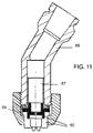
- Figure 11 shows how a nozzle such as nozzle 60 in communication with a connector 67 can be joined by a coupling 69 to a delivery hose (not shown) push-fitted over the end of coupling 69.
- the invention is further illustrated by the following Example.
- a viscous aqueous woodstain was made up by mixing together the ingredients shown in Table 1.
- the woodstain was found to have at 22° C a low sheer Brookfield viscosity of 2.8 to 3.0 pascal.sec, an ICI Cone and Plate viscosity of 0.02 pa.sec, a surface tension of 35 mN/m and density of 1.015 kg/litre.
- the woodstain was supplied in a 5 litre container into which a hand compressor capable of generating a pressure of 3 to at least 4.5 bar was fitted. Using the compressor, woodstain was taken from the container and delivered via a hose of 10 mm diameter to a nozzle as described with reference to Figures 5 to 10 of the drawings and expelled from its outlet.
Landscapes
- Paints Or Removers (AREA)
- Application Of Or Painting With Fluid Materials (AREA)
- Detergent Compositions (AREA)
Abstract
A process for the airless spray-coating of a surface with a viscous aqueous architectural coating composition wherein the composition is subjected to a pressure of from 2.5 to 5 bar and caused to flow through a nozzle comprising a plenum in communication with an outlet orifice having an elongated exit where a first dimension of the exit lies in a direction transverse to flow of the composition through the exit and is less than a third of a second dimension of the exit which also lies in a direction which is both transverse to flow of the composition through the exit but which is orthogonal to the direction of the first dimension. Also apparatus for the airless spray-coating of a surface with a viscous aqueous architectural coating composition, where the apparatus comprises preferably hand operated means for delivering the composition under pressure to a nozzle as described above.
The process and apparatus enable the viscous compositions to be applied quickly using low pressures easily generated by a hand compressor.
Description
- This invention relates to a process for the airless spray-coating of a surface with a viscous aqueous architectural coating composition (such as a woodstain, paint, lacquer or varnish) being a process able to cope with non-newtonian flow if necessary and which is suitable for use by amateur (ie. do-it-yourself) users who are usually unsophisticated and unlikely to want to invest in the expensive high pressure spraying apparatus currently used to spray viscous aqueous compositions. An "airless" spray-coating process is a process which does not require air to be mixed with the coating composition to assist its spraying.
- Architectural coating compositions are compositions which comprise an organic binder polymer which both binds a dried coat of the composition to a surface to which it has been applied and also binds into the dried coat any other ingredients of the composition such as pigments, dyes, opacifiers, extenders, thickeners and biocides. Architectural coatings are designed for application to surfaces found in or as part of buildings such as walls, ceilings, window frames, doors and door frames, radiators and customised furniture. They can also be designed for application to surfaces related to buildings and found in land (eg. gardens and yards) surrounding buildings. Such related surfaces include the stone or concrete surfaces of walls and the planed or rough cut wooden surfaces of fences, gates and sheds. Architectural coatings are intended to be applied by amateur and/or professional painters working on site at ambient temperatures and humidity.
- Architectural coating compositions generally have a viscosity at low sheer (ie. a Brookfield viscosity) of at least 0.5 pa.sec (pascal.second) so that when they are applied to a vertical surface, the applied coating does not "sag", ie. run down the surface before the coating has had time to dry enough to lose fluidity. "Sagging" is illustrated in Plate 14 of the "Handbook of Painting and Decorating Products" by A H Beckly published in 1983 by Granada of London, the contents of Plate 14 are herein incorporated by reference. In aqueous compositions, much of the viscosity is often imparted by the inclusion of thickeners such as celluloses and/or acrylic associative thickeners and both of these usually result in non-newtonian flow sufficient to complicate low pressure spraying from an orifice.
- Many surfaces, especially the surfaces of rough cut (ie. unplaned) wood, are left uncoated even in circumstances where they would benefit from the decorative or protective results achievable using architectural coatings. It is estimated that in Britain, two thirds of surfaces which could benefit from aqueous coatings are nevertheless left uncoated because coating by brush or roller is too time consuming. For example when the coating composition is aqueous and viscous, a standard size fence panel of rough cut wood takes about 9 to 10 minutes to coat by brush or 4 to 5 minutes to coat by roller. A professional painter using an electrically powered airless high pressure spraying apparatus operating at pressures of over 50 bar can coat the same panel in 30 to 60 seconds. Unfortunately, few amateur users would want to purchase such electrically powered apparatus nor would they be comfortable using such high pressures.
- Inexpensive low pressure spraying apparatus which can be pressurised up to about 3 bar using a hand-operated compressor (sometimes inaccurately called a "hand pump") is available for spraying organic solvent-based liquids of negligible Brookfield viscosity such as woodstains, fungicides and insecticides and is widely used by amateurs. The organic solvents (eg. white spirit) which are used in these compositions are now increasingly environmentally unwelcome, but attempts to use the same apparatus to spray aqueous architectural coating compositions (particularly aqueous woodstains) having a Brookfield viscosity at 22° C of at least 0.5 (but generally not over 50 and usually 1 to 12) pa.sec have resulted in the production of approximately cylindrical jets of small radii which impact onto no more than a tiny approximately circular area of a target surface. The small size of this area makes the coating process very time consuming.
- For quick coating, it is also desirable that the spraying apparatus be capable of spraying large volumes per minute of the architectural coating composition. It is preferred that a volume velocity of at least 0.2 (preferably 0.3 to 0.7) litre/minute of composition be delivered otherwise the target surface can only be traversed slowly.
- As a result of the discovery which lead to this invention, it has now been found possible to devise a spraying nozzle geometry which enables the provision of a quick process for the airless spray-coating of a surface with a viscous aqueous architectural coating composition even when employing inexpensive spraying apparatus operating at pressures low enough to be used comfortably by an amateur and to be easily generated using a hand operated compressor.
- Accordingly, this invention provides a process for the airless spray-coating of a surface with a viscous aqueous architectural coating composition wherein the composition is subjected to a pressure of from 2.5 to 5 (preferably 3 to 4.3) bar and caused to flow through a nozzle comprising a plenum in communication with an outlet orifice having an elongated exit where a first dimension of the exit which lies in a direction transverse to flow of the composition through the exit is less than a third of a second dimension of the exit which lies in a direction which is both transverse to flow of the composition through the exit and orthogonal to the direction of the first dimension. Preferably the first exit dimension has a maximum size of 0.25 to 0.45 mm (preferably 0.3 to 0.4 mm) and the second exit dimension has a size of from 0,5 to 1.5 mm.
- It has been discovered that when viscous aqueous architectural coating compositions are delivered to a nozzle according to this invention but at a pressure of below 2.5 bar, the composition expelled from the exit from the outlet orifice forms a flow which is initially divergent, but its boundaries soon converge to form an approximately cylindrical jet which quickly breaks up into a stream of large drops of irregular size. When aimed at a target surface, the stream of large drops coats only a tiny area of the surface and so coating the whole surface would be a very slow process. This sequence of events is illustrated in Figure 1 of the drawings. The true nature of the flows associated with the spraying apparatus is not properly understood, but it is supposed that at pressures below 2.5 bar, the surface tension of the composition is quite large relative to the inertial forces present in the composition as it leaves the exit from the outlet orifice and so surface tension quickly draws in the boundaries of the flow to form the approximately cylindrical jet followed by the large irregular drops.
- Increasing the delivery pressure accelerates the flow through the outlet orifice and it is supposed that this brings the inertial forces more into balance with the surface tension and so produces a longer, wider and more planar flow as illustrated in Figure 2. Once again the flow has initially divergent boundaries which are subsequently caused to converge presumably by surface tension before the flow again disintegrates into large drops. The disintegration only occurs after the flow has presented the relatively wider front spaced at a greater and therefore more convenient distance from the outlet. This wider front can be traversed across a target surface whereupon it applies bands of coating composition of widths similar to those obtained using a typical small paint brush of say 30 mm width. Therefore it provides a usable but relatively slow coating process.
- If the delivery pressure is increased to over 3 bar, it is supposed that the inertial forces and surface tension come into closer balance with the result that the flow widens to give an approximately parabolic fantail as illustrated by Figure 3. Using pressures above 3.5 bar, this fantail can reach widths of over 100 mm before it to breaks up into large drops. Such widths correspond to quite wide brushes, so provided the composition is being sprayed at a useful volume per minute, the composition can be applied very quickly across a target surface. As it leaves the outlet orifice, the fantail comprises a homogenous distribution of the composition which is important for acceptably uniform coating, but it not known whether the fantail comprises an integral sheet of liquid or a mist of closely spaced fine droplets or possibly a combination of both.
- Finally, increasing the pressure to somewhere between 4.5 and 5 bar causes the flow to break up close to the outlet orifice. This causes the expelled composition to form very large drops very quickly as illustrated in Figure 4. Such large drops give very inhomogeneous coatings often characterised by the appearance of streaks. It is supposed that the inertial forces now greatly exceed the ability of surface tension to control the shape of the flow. The preferred range of pressures forming an optimum fantail is therefore 3.5 to 4.5 bar, though a range of 3.2 to 3.6 bar may be better suited for use by less physically strong female amateurs.
- Selecting an optimum nozzle geometry is a simple matter. It is suggested that to begin, a nozzle should be chosen whose outlet exit has first and second and dimensions in about the middle of the preferred ranges, say 0.33 mm and 0.75 mm respectively and then the delivery pressure can be varied stepwise from 3.2 to 4.5 bar to investigate how the flow varies with pressure in this range. If a flow of greater width is preferred, the nozzle should be replaced by one having an outlet exit whose first dimension is less than 0.33 mm so as to increase sheer and consequently reduce the viscosity of the composition being expelled. This increases the speed of expulsion and the width of the flow presumably because the inertial forces in the system increase with the velocity and so surface tension yields a wider flow.
- Conversely, if a narrower flow is preferred for say coating narrower items such as door or window frames, the first dimension of the outlet exit should increased to more than 0.33 mm thereby reducing shear and retaining more of the viscosity. This decreases the speed of expulsion and hence the inertial forces and so presumably surface tension draws in the width of the flow.
- Speed of expulsion and therefore the width of the flow can also be varied at a constant delivery pressure by varying the second dimension of the outlet orifice. Increasing the second dimension decreases the speed of the flow leaving the outlet orifice and hence decreases the width of the flow. Conversely, decreasing the second dimension increases the speed of the flow leaving the outlet orifice and hence increases the width of the flow.
- For ease of spraying, it is preferred that the viscosities at 22° C of the compositions should reduce to 0.015 to 0.5 pa.sec under high shear, say a shear rate of 10 000/sec as measured by an ICI Cone and Plate viscometer as described in ASTM Test D4827- 88.
- The plenum leading to the outlet may also be usefully employed to govern the viscosity of the composition in the region of the outlet provided that the plenum has an appropriate geometry. Preferably the plenum should have a dimension transverse to the flow through the nozzle of from 0.5 to 3 (especially 1.3 to 2.7) mm and a length of 0.2 to 4 (especially 0.2 to 3) mm. Most conveniently it should be cylindrical and of about the same transverse dimension (ie. radius) as the second transverse dimension of the outlet orifice. Increasing the transverse dimensions and/or decreasing the longitudinal dimension of the plenum decreases the shear and loss of viscosity leading to a slower speed of expulsion from the outlet orifice and a narrower flow. Conversely, decreasing the transverse dimensions and/or increasing the longitudinal dimension increases the shear and the loss of viscosity leading to a faster speed of expulsion from the outlet orifice and a wider flow.
- A preferred outlet nozzle geometry comprises a plenum terminating with a hemispherical end which is blind except for the entrance to the outlet orifice. The orifice is preferably defined by the notional intrusion into the hemisphere of a wedge shape consisting of two opposed mutually inclined planes which meet to define a notional leading edge inside the plenum. The leading edge in effect defines the second dimension of the exit from the outlet orifice. The maximum first dimension of the outlet exit is defined by the maximum distance between the inclined planes as they enter the hemispherical end of the plenum.
- The planes are preferably inclined at into the plenum an angle of from 25° to 55° (especially 35° to 45°). Preferably, the leading edge intrudes to a point either lying on the "terminal plane" of the hemisphere or lying on a parallel plane either just upstream or just downstream of the terminal plane. The "terminal plane" of the hemisphere is the circular plane of radius equal to the radius of the sphere of which the hemisphere forms half.
- Where the wedge shape penetrates no further than the terminal plane of the hemisphere, the outlet exit has a projected shape which is elliptical. If the wedge penetrates further, the projected shape is that of a curtailed ellipse whose ends are defined by the cylindrical part of the plenum and so are curtailed and have a smaller curvature than would be the case if the shape were truly elliptical. The smaller curvature is more likely to give an even coating and in particular, the coating is less likely to contain streaks. Preferably, the parallel planes should be no more than 0.8 mm upstream or downstream of the terminal plane.
- The portions of the mutually inclined planes of the wedge shape which are within the hemisphere together define two opposed mutually inclined surfaces which are essentially semi-circular. This means that composition flowing in the central regions of the outlet orifice will be in closer proximity to a surface of the outlet orifice for a longer period of time than composition flowing in the lateral regions of the outlet. Composition in the central region will therefore receive more shear in the outlet orifice than composition in the lateral regions which may compensate for the fact that composition in the central region may have received less shear elsewhere. It is possible that this compensation assists in creating a more homogenous coating of a target surface.
- In order to minimise any pressure pulses which might arise from irregular hand compression, the nozzle can usefully also comprise a large chamber upstream of, and in communication with its plenum. Provided that the chamber is large relative to the plenum, its precise dimensions are not critical but for guidance, it is proposed that its transverse dimensions be about 5 to 10 times the transverse dimensions of the plenum and its length be 5 to 20 (preferably 6 to 8) mm.
- In a refinement of the nozzle, it is additionally provided with an auxiliary (preferably circular) orifice upstream of the plenum which receives composition under the delivery pressure of from 2.5 to 5 bar and directs it towards the plenum. The preferred transverse dimension of the auxiliary orifice is from 0.8 to 1.5 mm, its preferred length is from 1.7 to 2.3 mm and the pressure drop across the orifice is preferably from 0.5 to 2 bar. Preferably composition flows from the auxiliary orifice into a chamber of large transverse dimension as described above and then into the plenum. The use of this auxiliary orifice and large chamber can increase the width of the laminar flow expelled from the main outlet to well over 120 mm, often reaching over 400 mm. This provides an extremely quick coating process.
- An unexpected advantage of the refined nozzle is its resistance to blockages. Most aqueous paints are at risk of containing a small concentration of unwanted agglomerates of pigment or opacifier particles, usually agglomerates of 200 µm or greater where one µm equals 10-6 m. Agglomerates can accumulate in a nozzle and block its outlet orifice. It is supposed that the conditions of shear in the refined nozzle are sufficient to break down the agglomerates.
- Other factors which might affect the balance between the inertial forces and surface tension and therefore the width and stability of the expelled flow are of course the size of the surface tension itself and the density of the composition. Both are determined by the complex formulations used to make modern architectural coating compositions and so it is not easy to vary either. In theory, surface tension can be reduced by adding detergents to a composition, but this often increases the sensitivity of the composition to water, eg. the sensitivity of a paint to rain. Hence, variation of surface tension is seldom a practical option. Most architectural paints will have a surface tension at 22° C in the range of 23 to 45 N.10-3m.
- Density is strongly influenced in the architectural coating compositions by the concentration of heavy inorganic opacifiers such as rutile titanium dioxide (which also serves as a white pigment) or of coloured pigments or extenders such as chalk or clays. Pigment and extender concentrations are carefully chosen to give a colour of precise hue, chroma or lightness, so varying their concentration merely to adjust density is seldom practical. In short, density cannot be significantly varied without unacceptable consequences for opacity and colour. Generally the density of an architectural coating composition is from 1.01 to 1.6 kg/litre and is usually 1.01 to 1.2 kg/litre for woodstains and fungicides and 1.2 to 1.6 kg/litre for paints if dense pigments or opacifiers such as rutile are needed.
- A wide variety of conventional film-forming binder polymers are available for use in architectural coating compositions, but those most commonly used are of three broad types obtained from mono-ethylenically unsaturated monomers and known colloquially as "acrylics", "vinyls" or "styrenics". The "acrylics" are usually copolymers of at least two alkyl esters of one or more mono-ethylenically unsaturated carboxylic acids (e.g. methyl methacrylate/butyl acrylate copolymer) whilst the "vinyls" usually comprise copolymers of a mono-vinyl ester of a saturated carboxylic acid such as vinyl acetate and at least one of either an acrylic monomer or a different mono-vinyl ester, often the vinyl ester of a carboxylic acid containing 10 to 12 carbon atoms such as those sold under the trade name "Versatate" by Resolution Europe BV of Rotterdam. The "styrenics" are copolymers containing styrene (or a similar mono-vinyl aromatic monomer) together with a copolymerisable monomer which is usually an acrylic.
- This invention also provides apparatus for the airless spray-coating of a surface with a viscous aqueous architectural coating composition, where the apparatus comprises (preferably hand operated) means for delivering the composition under pressure to a nozzle comprising a plenum in communication with an outlet orifice having an elongated exit where a first dimension of the exit which lies in a direction transverse to flow of the composition through the exit is from 0.2 to 0.45 mm (preferably 0.3 to 0.4 mm) and a second dimension of the exit which lies in a direction which is both transverse to flow of the composition through the exit and orthogonal to the direction of the first dimension is from 0.5 to 1.5 mm.
- The apparatus may also comprise a container filled with an architectural coating composition having viscosity and a surface tension within the ranges hereinbefore described. It may be fitted with a pressure gauge to indicate a pressure in the range 2.5 to 5 bar and a pressure relief valve activatable when the pressure exceeds a suitable maximum of say 5 bar, preferably 3.2 to 4.5 bar.
- Although this invention is primarily intended for use with hand operated compressors, it could make of pressures generated by low pressure domestic compressors.
- Brookfield viscosity was measured at 22°C using a Brookfield Viscometer, Model HA as supplied by Brookfield Engineering Laboratories Incorporated of Middleboro, Massachusetts. Essentially, a Brookfield Viscometer comprises a rotateable spindle which carries a disc which, when performing the measurement, is immersed into the coating composition about 10 mm below its surface. The composition should be provided in a cylindrical container having a diameter of at least 100 mm so as to avoid errors due to the proximity of the container walls.
- To perform the measurement for the purposes of this description, a Brookfield No. 3 Spindle is chosen, immersed into the composition and then rotated at Brookfield Speed No 10 for at least three revolutions. The spindle is coupled to a torque measuring device which is calibrated to express torque in terms of the viscosity of the composition either directly or after the operation of a multiplier specified by Brookfield.
- This invention and a preferred embodiment will now be illustrated with reference to drawings of which:
- Figure 1 is a diagrammatic representation of a flow expelled from the outlet when the delivery pressure is below 2.5 bar.
- Figure 2 is a diagrammatic representation of the flow expelled from the outlet when the delivery pressure is above 2.5 bar.
- Figure 3 is a diagrammatic representation of the fantail flow expelled from the outlet when the delivery pressure is in the optimum range of 3 to 4 bar.
- Figure 4 is a diagrammatic representation of the flow expelled from the outlet when the delivery pressure is above 5 bar.
- Figure 5 is a front elevation of a nozzle according to this invention,
- Figure 6 is a section through the nozzle taken on line A-A in Figure
- Figure 7 is a section through the nozzle taken on line B-B in Figure 1,
- Figure 8 shows on a larger scale the zone around the hemispherical end and wedge-shape shown in Figures 6 and 7.
- Figure 9 shows a modified outlet orifice on larger scale.
- Figure 10 shows a refinement of the invention in section and on a larger scale.
- Figure 11 shows a nozzle connected to a coupling for a delivery hose.
- Figure 1 illustrates the shape of a
flow 11 of composition expelled fromexit 2 of an outlet orifice which shape is to be expected when the delivery pressure is less than 2.5 bar.Flow 11 has an initially flat profile which quickly converges into an approximatelycylindrical jet 12.Jet 12 is unstable and breaks up into largeirregular droplets 13 before strikingsmall zone 3 oftarget surface 4 which is spaced 650 mm fromexit 2. - Figure 2 illustrates the effects of increasing the delivery pressure beyond 2.5 bar whereupon expelled
flow 21 has a flat profile but is wider in a direction transverse of direction the flow of composition throughexit 2 and extends further from the exit before breaking up into largeirregular droplets 22.Flow 21 begins by diverging transversely and then converges to aconstriction 24 before becoming unstable and breaking up intodroplets 22. Because of the greater width offlow 21, it would be possible to use it for a moderately quick coating of atarget surface 4a (shown in broken lines) positioned nearer tooutlet orifice 2 thansurface 4 and upstream ofconstriction 24. - Figure 3 illustrates the effects of increasing the delivery pressure to an optimum range of 3.5 to 4 bar. A
flat flow 31 is obtained which diverges transversely producing a shape having essentiallyparabolic boundaries 35 and which remains stable until it strikestarget surface 4. The width offlow 31 increases to over 100 mm by the time it strikestarget surface 4. - Figure 4 illustrates the effects of a delivery pressure beyond 5 bar whereupon expelled
flow 41 still has a flat profile but is unstable as it leavesoutlet orifice 2 and quickly disintegrates into largeirregular droplets 43 long before it reachestarget surface 4. - Figure 5 shows the front elevation of a
preferred nozzle 50 havingopening 51 a leading to wedge-shapedspace 51 which (as shown in Figures 6, 7 and 8) comprisesinclined planes 51 b. As best shown in Figure 8, planes 51 b intrude throughhemispherical end 54a ofplenum 54 sodefining exit 52a tooutlet orifice 52. The inclined planes subtend an angle of 40° and terminate in a notionalleading edge 51 c lying in terminal plane 54b ofhemispherical end 54a. The distance as shown in Figure 8 which extends betweenpoints hemispherical end 54a extends transversely of the flow of composition throughexit 52a and defines the maximum first dimension ofexit 52a. Leadingedge 51c extends transversely of the flow of composition throughexit 52a and is also orthogonal to the first dimension ofexit 52a and so when it is withinhemispherical end 54a, leadingedge 51 c defines the second dimension ofexit 52a. -
Hemispherical end 54a ofplenum 54 is blind except foroutlet orifice 52. -
Nozzle 50 has alarge chamber 53 which communicates with and is upstream ofplenum 54.Large chamber 53 communicates with aconnector 55 adapted to receive a hose (not shown) through which architectural coating composition under a pressure of 2.5 to 5 bar can be delivered.Large chamber 53 smoothes out any excessive pressure pulses and directs the delivered composition intoplenum 54 from where it passes throughoutlet orifice 52 and itsexit 52a to emerge as a spray.Opening 51 a andexit 52a are located in aprotective channel 57 defined byshoulders 58. - Figure 9 shows on a larger scale the projection of the shape of the exit from modified
outlet orifice 52x.Outlet orifice 52x is defined by a pair of mutually inclined planes which extend beyond the terminal plane of the hemisphere and into the cylindrical part of the plenum so conferring a curtailed elliptical shape onends 59x.Ends 59x are inset from the true elliptical shape and so have a lesser curvature which serves to reduce the tendency for a coating to be streaky. The minor diameter of the curtailed elliptical shape is the maximum first dimension of the exit whilst its curtailed maximum diameter is the second dimension of the exit. - The nozzle may be moulded from a thermoplastics material such as polyacetal or polypropylene.
- Figure 10 shows a refinement of the embodiment shown in Figures 5 to 9. In Figure 10, two
part nozzle 60 hasplenum 64 which is shorter than plenum 54 shown in Figures 6 and 7.Plenum 64 receives composition under pressure from alarger chamber 65 which in turn receives it after it has passed throughauxiliary orifice 66.Auxiliary orifice 66 reduces the tendency for blockage by agglomerates in the composition and also results in a wider fantail. - Figure 11 shows how a nozzle such as
nozzle 60 in communication with aconnector 67 can be joined by acoupling 69 to a delivery hose (not shown) push-fitted over the end ofcoupling 69. - The invention is further illustrated by the following Example.
- A viscous aqueous woodstain was made up by mixing together the ingredients shown in Table 1. The woodstain was found to have at 22° C a low sheer Brookfield viscosity of 2.8 to 3.0 pascal.sec, an ICI Cone and Plate viscosity of 0.02 pa.sec, a surface tension of 35 mN/m and density of 1.015 kg/litre. The woodstain was supplied in a 5 litre container into which a hand compressor capable of generating a pressure of 3 to at least 4.5 bar was fitted. Using the compressor, woodstain was taken from the container and delivered via a hose of 10 mm diameter to a nozzle as described with reference to Figures 5 to 10 of the drawings and expelled from its outlet.
TABLE 1 Ingredient Weight % Water 92.7 Vinyl Acetate/Vinyl "Versate" copolymer 4.4 Coloured Pigment 2.3 Cellulose/Acrylic thickeners 0.5 Biocide 0.1
The process has been described with respect to architectural coating compositions, but it could also be used to spray other compositions having similar rheological or other properties.
Claims (11)
- A process for the airless spray-coating of a surface with a viscous aqueous architectural coating composition wherein the composition is subjected to a pressure of from 2.5 to 5 bar and caused to flow through a nozzle (50) comprising a plenum (54) in communication with an outlet orifice (52) having an elongated exit (52a) where a first dimension of the exit which lies in a direction transverse to flow of the composition through the exit is less than a third of a second dimension of the exit which lies in a direction which is both transverse to flow of the composition through the exit and orthogonal to the direction of the first dimension.
- A process according to Claim 1 wherein the first dimension is from 0.25 to 0.45 mm and the second dimension is from 0.5 to 1.5 mm.
- A process according to Claim 1 or Claim 2 wherein the pressure is from 3 to 4.5 bar.
- A process according to any one of Claims 1 to 3 wherein the composition is passed through an auxiliary orifice (66) upstream of the plenum.
- A process according to any one of Claims 1 to 4 wherein the projection of the exit from the outlet oriface is essentially elliptical or curtailed elliptical.
- A process according to Claim 5 wherein the plenum is cylindrical terminating in a hemispherical end (54a) into which a wedge shape comprising inclined planes (51 b) notionally intrudes defining the outlet orifice.
- Apparatus for the airless spray-coating of a surface with a viscous aqueous architectural coating composition, where the apparatus comprises hand operated means for delivering the composition under pressure to a nozzle (50)comprising a plenum (54) in communication with an outlet orifice (52) having an elongated exit (52a) where a first dimension of the exit which lies in a direction transverse to flow of the composition through the exit is from 0.2 to 0.45 mm and a second dimension of the exit which lies in a direction which is both transverse to flow of the composition through the exit and orthogonal to the direction of the first dimension is from 0.5 to 1.5 mm.
- Apparatus according to Claim 7 wherein the plenum is cylindrical terminating in a hemispherical end (54a) into which a wedge shape comprising inclined planes (51 b) notionally intrudes defining the outlet orifice.
- Apparatus according to Claim 7 or Claim 8 wherein the projection of the exit from the outlet orifice is elliptical or curtailed elliptical.
- Apparatus according to any one of Claims 7 to 9 wherein the nozzle comprises an auxiliary orifice upstream of the plenum.
- Apparatus according to any one of Claims 7 to 10 wherein the apparatus includes a container filled with a coating composition having a Brookfield viscosity at 22° C of at least 0.5 pascal.sec.
Priority Applications (19)
| Application Number | Priority Date | Filing Date | Title |
|---|---|---|---|
| EP04380170A EP1627689A1 (en) | 2004-08-13 | 2004-08-13 | Method for airless spray-coating a surface with a viscous architectural aqueous coating composition |
| MX2007001766A MX2007001766A (en) | 2004-08-13 | 2005-08-10 | Airless spray-coating of a surface with a viscous aqueous architectural coating composition. |
| GB0617146A GB2426472C (en) | 2004-08-13 | 2005-08-10 | Airless spray-coating of a surface with a viscous aqueous architectural coating composition. |
| CN2005800271943A CN101022891B (en) | 2004-08-13 | 2005-08-10 | Airless Spray Application of Surfaces Using Viscous Aqueous Architectural Coating Components |
| PL05076856T PL1625891T3 (en) | 2004-08-13 | 2005-08-10 | Airless spray-coating of a surface with a viscous aqueous architectural coating composition |
| EP05772640.8A EP1824604B1 (en) | 2004-08-13 | 2005-08-10 | Airless spray-coating of a surface with a viscous aqueous architectural coating composition |
| BRPI0514202-4A BRPI0514202B1 (en) | 2004-08-13 | 2005-08-10 | A process for the airless coating of a vertical surface with a non-Newtonian viscous watery coat composition, and an apparatus for the airless coating of a surface coating of a non-walled coating |
| PCT/EP2005/008760 WO2006015869A1 (en) | 2004-08-13 | 2005-08-10 | Airless spray-coating of a surface with a viscous aqueous architectural coating composition |
| DK05076856.3T DK1625891T3 (en) | 2004-08-13 | 2005-08-10 | Airless spray coating of a surface with a viscous aqueous coating composition |
| RU2007109159/11A RU2352404C2 (en) | 2004-08-13 | 2005-08-10 | Application of construction coating viscous water composition on surface by dispersion without air |
| EP05076856.3A EP1625891B1 (en) | 2004-08-13 | 2005-08-10 | Airless spray-coating of a surface with a viscous aqueous architectural coating composition |
| CA2576587A CA2576587C (en) | 2004-08-13 | 2005-08-10 | Airless spray-coating of a surface with a viscous aqueous architectural coating composition |
| ES05076856.3T ES2445823T3 (en) | 2004-08-13 | 2005-08-10 | Airless spray coating of a surface with an aqueous and viscous architectural coating composition |
| UY29067A UY29067A1 (en) | 2004-08-13 | 2005-08-12 | AIRLESS SPRAY COATING OF A SURFACE WITH A WATERY VISCOSE COMPOSITION OF ARCHITECTURAL COATING |
| ARP050103388A AR051072A1 (en) | 2004-08-13 | 2005-08-12 | AIRLESS SPRAY COATING OF A SURFACE WITH A WATERY VISCOSE COMPOSITION OF ARCHITECTURAL COATING |
| MYPI20053800A MY140993A (en) | 2004-08-13 | 2005-08-12 | Airless spray-coating of a surface with a viscous aqueous architectural coating composition |
| GBGB0624151.7A GB0624151D0 (en) | 2004-08-13 | 2006-12-04 | Airless spray-coating of a surface with a viscous aqueous architectural coating composition |
| US11/674,535 US20070224358A1 (en) | 2004-08-13 | 2007-02-13 | Airless spray-coating of a surface with an aqueous architectural coating composition |
| GBGB0706377.9A GB0706377D0 (en) | 2004-08-13 | 2007-04-02 | Airless spray-coating of a surface with a viscous aqueous architectural coating composition |
Applications Claiming Priority (1)
| Application Number | Priority Date | Filing Date | Title |
|---|---|---|---|
| EP04380170A EP1627689A1 (en) | 2004-08-13 | 2004-08-13 | Method for airless spray-coating a surface with a viscous architectural aqueous coating composition |
Publications (1)
| Publication Number | Publication Date |
|---|---|
| EP1627689A1 true EP1627689A1 (en) | 2006-02-22 |
Family
ID=34938393
Family Applications (2)
| Application Number | Title | Priority Date | Filing Date |
|---|---|---|---|
| EP04380170A Withdrawn EP1627689A1 (en) | 2004-08-13 | 2004-08-13 | Method for airless spray-coating a surface with a viscous architectural aqueous coating composition |
| EP05772640.8A Expired - Lifetime EP1824604B1 (en) | 2004-08-13 | 2005-08-10 | Airless spray-coating of a surface with a viscous aqueous architectural coating composition |
Family Applications After (1)
| Application Number | Title | Priority Date | Filing Date |
|---|---|---|---|
| EP05772640.8A Expired - Lifetime EP1824604B1 (en) | 2004-08-13 | 2005-08-10 | Airless spray-coating of a surface with a viscous aqueous architectural coating composition |
Country Status (14)
| Country | Link |
|---|---|
| US (1) | US20070224358A1 (en) |
| EP (2) | EP1627689A1 (en) |
| CN (1) | CN101022891B (en) |
| AR (1) | AR051072A1 (en) |
| BR (1) | BRPI0514202B1 (en) |
| CA (1) | CA2576587C (en) |
| DK (1) | DK1625891T3 (en) |
| ES (1) | ES2445823T3 (en) |
| GB (3) | GB2426472C (en) |
| MX (1) | MX2007001766A (en) |
| MY (1) | MY140993A (en) |
| RU (1) | RU2352404C2 (en) |
| UY (1) | UY29067A1 (en) |
| WO (1) | WO2006015869A1 (en) |
Cited By (8)
| Publication number | Priority date | Publication date | Assignee | Title |
|---|---|---|---|---|
| WO2007079932A1 (en) * | 2006-01-13 | 2007-07-19 | Imperial Chemical Industries Plc | Non-pneumatically asissted spray-coating of a surface with a viscous aqueous architectural coating composition |
| EP2100668A1 (en) * | 2008-03-14 | 2009-09-16 | Exel Industries | Spray nozzle and liquid spraying device comprising said spray nozzle |
| CN102202802A (en) * | 2008-10-22 | 2011-09-28 | 格瑞克明尼苏达有限公司 | Portable airless sprayer |
| US9545643B2 (en) | 2008-10-22 | 2017-01-17 | Graco Minnesota Inc. | Portable airless sprayer |
| US10926275B1 (en) | 2020-06-25 | 2021-02-23 | Graco Minnesota Inc. | Electrostatic handheld sprayer |
| US10968903B1 (en) | 2020-06-04 | 2021-04-06 | Graco Minnesota Inc. | Handheld sanitary fluid sprayer having resilient polymer pump cylinder |
| US11707753B2 (en) | 2019-05-31 | 2023-07-25 | Graco Minnesota Inc. | Handheld fluid sprayer |
| US11986850B2 (en) | 2018-04-10 | 2024-05-21 | Graco Minnesota Inc. | Handheld airless sprayer for paints and other coatings |
Families Citing this family (12)
| Publication number | Priority date | Publication date | Assignee | Title |
|---|---|---|---|---|
| KR101695045B1 (en) | 2009-05-07 | 2017-01-10 | 그라코 미네소타 인크. | Wobble assembly for fluid pumping mechanism |
| US9592516B2 (en) * | 2009-09-08 | 2017-03-14 | Basf Se | Polyurethane spraying system used to minimize emissions of a polyisocyanate |
| MX2010009775A (en) | 2009-09-08 | 2011-06-15 | Basf Se | Method for minimizing emissions while forming a polyurethane foam. |
| NL2012409B1 (en) * | 2014-03-12 | 2015-11-26 | Saba Dinxperlo B V | Improved low pressure 2-K handheld spray gun. |
| CN106319932B (en) * | 2015-07-10 | 2018-12-18 | 国网智能电网研究院 | A kind of carbon nanotube laying apparatu for carbon fiber |
| EP3387073B1 (en) * | 2015-12-10 | 2020-02-05 | Akzo Nobel Coatings International B.V. | Foamed coating composition and method for coating a substrate with such coating composition |
| US11007545B2 (en) | 2017-01-15 | 2021-05-18 | Graco Minnesota Inc. | Handheld airless paint sprayer repair |
| US12539525B2 (en) | 2017-11-30 | 2026-02-03 | Axalta Coating Systems Ip Co., Llc | Coating compositions for application utilizing a high transfer efficiency applicator and methods and systems thereof |
| WO2019109042A1 (en) * | 2017-11-30 | 2019-06-06 | KOERNER, Michael R. | Systems for applying coating compositions utilizing a high transfer efficiency applicator and corresponding methods |
| CN109868057A (en) * | 2017-12-01 | 2019-06-11 | 辽宁法库陶瓷工程技术研究中心 | A kind of fiber reinforcement antiscour ablation surface and the preparation method and application thereof |
| AT522763B1 (en) | 2019-12-05 | 2021-01-15 | Metallconcept Gmbh | Printhead |
| US12122932B2 (en) | 2020-05-29 | 2024-10-22 | Axalta Coating Systems Ip Co., Llc | Coating compositions for application utilizing a high transfer efficiency applicator and methods and systems thereof |
Citations (5)
| Publication number | Priority date | Publication date | Assignee | Title |
|---|---|---|---|---|
| US3556411A (en) * | 1968-05-22 | 1971-01-19 | Nordson Corp | Spray nozzle |
| US4346849A (en) * | 1976-07-19 | 1982-08-31 | Nordson Corporation | Airless spray nozzle and method of making it |
| US4753819A (en) * | 1985-12-27 | 1988-06-28 | Nordson Corporation | Method for applying a moistureproof insulator coating on packaged circuit boards |
| EP0584973A2 (en) * | 1992-08-27 | 1994-03-02 | Nordson Corporation | Spray gun for substrate coating |
| US6013315A (en) * | 1998-01-22 | 2000-01-11 | Applied Materials, Inc. | Dispense nozzle design and dispense method |
Family Cites Families (11)
| Publication number | Priority date | Publication date | Assignee | Title |
|---|---|---|---|---|
| US4204645A (en) * | 1978-05-17 | 1980-05-27 | Column Corporation | General purpose compression-type sprayer |
| SU957976A1 (en) * | 1981-02-25 | 1982-09-15 | Научно-Исследовательский Институт Научно-Производственного Объединения "Лакокраспокрытие" | Spraying apparatus |
| US4406704A (en) * | 1982-04-16 | 1983-09-27 | Westinghouse Electric Corp. | High-solids single-package air-dryable primer |
| US4756481A (en) * | 1986-11-24 | 1988-07-12 | Theo Krebs Ag | Apparatus for spraying a flowable mass and including an airless spray gun |
| US5017409A (en) * | 1988-06-13 | 1991-05-21 | Union Carbide Chemicals And Plastics Technology Corporation | Method of conformal coating |
| US6428844B1 (en) | 1993-02-03 | 2002-08-06 | Rohm And Haas Company | Reduction of microfoam in a spray-applied waterborne composition |
| US5486576A (en) | 1994-07-01 | 1996-01-23 | Rohm And Haas Company | Method for reducing microfoam in a spray-applied waterborne thermoset composition |
| US6168093B1 (en) * | 1998-12-30 | 2001-01-02 | Homax Products, Inc. | Airless system for spraying coating material |
| US20030025002A1 (en) * | 2001-08-04 | 2003-02-06 | Jeffrey Hughes | Pressurizable fluid spray system |
| TW200404820A (en) * | 2002-06-14 | 2004-04-01 | Rohm & Haas | Aqueous nanoparticle dispersions |
| CA2441141A1 (en) * | 2002-09-30 | 2004-03-30 | Armstrong World Industries, Inc. | Acoustical panel coating and process of applying same |
-
2004
- 2004-08-13 EP EP04380170A patent/EP1627689A1/en not_active Withdrawn
-
2005
- 2005-08-10 ES ES05076856.3T patent/ES2445823T3/en not_active Expired - Lifetime
- 2005-08-10 RU RU2007109159/11A patent/RU2352404C2/en active
- 2005-08-10 BR BRPI0514202-4A patent/BRPI0514202B1/en active IP Right Grant
- 2005-08-10 EP EP05772640.8A patent/EP1824604B1/en not_active Expired - Lifetime
- 2005-08-10 CA CA2576587A patent/CA2576587C/en not_active Expired - Fee Related
- 2005-08-10 MX MX2007001766A patent/MX2007001766A/en unknown
- 2005-08-10 CN CN2005800271943A patent/CN101022891B/en not_active Expired - Fee Related
- 2005-08-10 DK DK05076856.3T patent/DK1625891T3/en active
- 2005-08-10 WO PCT/EP2005/008760 patent/WO2006015869A1/en not_active Ceased
- 2005-08-10 GB GB0617146A patent/GB2426472C/en not_active Expired - Lifetime
- 2005-08-12 UY UY29067A patent/UY29067A1/en not_active Application Discontinuation
- 2005-08-12 MY MYPI20053800A patent/MY140993A/en unknown
- 2005-08-12 AR ARP050103388A patent/AR051072A1/en active IP Right Grant
-
2006
- 2006-12-04 GB GBGB0624151.7A patent/GB0624151D0/en not_active Ceased
-
2007
- 2007-02-13 US US11/674,535 patent/US20070224358A1/en not_active Abandoned
- 2007-04-02 GB GBGB0706377.9A patent/GB0706377D0/en not_active Ceased
Patent Citations (5)
| Publication number | Priority date | Publication date | Assignee | Title |
|---|---|---|---|---|
| US3556411A (en) * | 1968-05-22 | 1971-01-19 | Nordson Corp | Spray nozzle |
| US4346849A (en) * | 1976-07-19 | 1982-08-31 | Nordson Corporation | Airless spray nozzle and method of making it |
| US4753819A (en) * | 1985-12-27 | 1988-06-28 | Nordson Corporation | Method for applying a moistureproof insulator coating on packaged circuit boards |
| EP0584973A2 (en) * | 1992-08-27 | 1994-03-02 | Nordson Corporation | Spray gun for substrate coating |
| US6013315A (en) * | 1998-01-22 | 2000-01-11 | Applied Materials, Inc. | Dispense nozzle design and dispense method |
Cited By (26)
| Publication number | Priority date | Publication date | Assignee | Title |
|---|---|---|---|---|
| CN101384375B (en) * | 2006-01-13 | 2013-08-21 | 帝国化学工业公司 | Non-pneumatically asissted spray-coating of a surface with a viscous aqueous architectural coating composition |
| EP1810754A1 (en) * | 2006-01-13 | 2007-07-25 | Imperial Chemical Industries Plc. | Non-pheumatically assisted spray-coating of a surface with viscous aqueous architectural coating composition |
| WO2007079932A1 (en) * | 2006-01-13 | 2007-07-19 | Imperial Chemical Industries Plc | Non-pneumatically asissted spray-coating of a surface with a viscous aqueous architectural coating composition |
| EP2100668A1 (en) * | 2008-03-14 | 2009-09-16 | Exel Industries | Spray nozzle and liquid spraying device comprising said spray nozzle |
| FR2928567A1 (en) * | 2008-03-14 | 2009-09-18 | Exel Ind Sa | LIQUID SPRAY NOZZLE AND LIQUID SPRAYER COMPRISING SUCH A NOZZLE |
| US10919060B2 (en) | 2008-10-22 | 2021-02-16 | Graco Minnesota Inc. | Portable airless sprayer |
| US11446689B2 (en) | 2008-10-22 | 2022-09-20 | Graco Minnesota Inc. | Portable airless sprayer |
| US9517479B2 (en) | 2008-10-22 | 2016-12-13 | Graco Minnesota Inc. | Portable airless sprayer |
| US9545643B2 (en) | 2008-10-22 | 2017-01-17 | Graco Minnesota Inc. | Portable airless sprayer |
| US9604235B2 (en) | 2008-10-22 | 2017-03-28 | Graco Minnesota Inc. | Portable airless sprayer |
| US9604234B2 (en) | 2008-10-22 | 2017-03-28 | Graco Minnesota Inc. | Portable airless sprayer |
| US9914141B2 (en) | 2008-10-22 | 2018-03-13 | Graco Minnesota, Inc. | Portable airless sprayer |
| CN102202802A (en) * | 2008-10-22 | 2011-09-28 | 格瑞克明尼苏达有限公司 | Portable airless sprayer |
| US12605727B2 (en) | 2008-10-22 | 2026-04-21 | Graco Minnesota Inc. | Portable airless sprayer |
| US12145169B2 (en) | 2008-10-22 | 2024-11-19 | Graco Minnesota Inc. | Portable airless sprayer |
| US11446690B2 (en) | 2008-10-22 | 2022-09-20 | Graco Minnesota Inc. | Portable airless sprayer |
| CN102202802B (en) * | 2008-10-22 | 2014-06-11 | 格瑞克明尼苏达有限公司 | Portable airless sprayer |
| US11623234B2 (en) | 2008-10-22 | 2023-04-11 | Graco Minnesota Inc. | Portable airless sprayer |
| US11779945B2 (en) | 2008-10-22 | 2023-10-10 | Graco Minnesota Inc. | Portable airless sprayer |
| US11759808B1 (en) | 2008-10-22 | 2023-09-19 | Graco Minnesota Inc. | Portable airless sprayer |
| US11986850B2 (en) | 2018-04-10 | 2024-05-21 | Graco Minnesota Inc. | Handheld airless sprayer for paints and other coatings |
| US11707753B2 (en) | 2019-05-31 | 2023-07-25 | Graco Minnesota Inc. | Handheld fluid sprayer |
| US12208411B2 (en) | 2019-05-31 | 2025-01-28 | Graco Minnesota Inc. | Handheld fluid sprayer |
| US10968903B1 (en) | 2020-06-04 | 2021-04-06 | Graco Minnesota Inc. | Handheld sanitary fluid sprayer having resilient polymer pump cylinder |
| US11738358B2 (en) | 2020-06-25 | 2023-08-29 | Graco Minnesota Inc. | Electrostatic handheld sprayer |
| US10926275B1 (en) | 2020-06-25 | 2021-02-23 | Graco Minnesota Inc. | Electrostatic handheld sprayer |
Also Published As
| Publication number | Publication date |
|---|---|
| CN101022891B (en) | 2010-12-29 |
| GB0706377D0 (en) | 2007-05-09 |
| GB2426472A (en) | 2006-11-29 |
| US20070224358A1 (en) | 2007-09-27 |
| RU2007109159A (en) | 2008-09-20 |
| GB0624151D0 (en) | 2007-01-10 |
| EP1824604A1 (en) | 2007-08-29 |
| BRPI0514202B1 (en) | 2018-03-13 |
| MY140993A (en) | 2010-02-12 |
| CA2576587C (en) | 2012-12-18 |
| BRPI0514202A (en) | 2008-06-03 |
| RU2352404C2 (en) | 2009-04-20 |
| DK1625891T3 (en) | 2014-03-31 |
| GB2426472B (en) | 2007-03-07 |
| AR051072A1 (en) | 2006-12-20 |
| GB2426472C (en) | 2007-03-07 |
| EP1824604B1 (en) | 2014-04-09 |
| CA2576587A1 (en) | 2006-02-16 |
| GB0617146D0 (en) | 2006-10-18 |
| UY29067A1 (en) | 2005-12-30 |
| ES2445823T3 (en) | 2014-03-05 |
| WO2006015869A1 (en) | 2006-02-16 |
| MX2007001766A (en) | 2007-05-04 |
| CN101022891A (en) | 2007-08-22 |
Similar Documents
| Publication | Publication Date | Title |
|---|---|---|
| EP1824604B1 (en) | Airless spray-coating of a surface with a viscous aqueous architectural coating composition | |
| EP1976646B1 (en) | Non-pneumatically asissted spray-coating of a surface with a viscous aqueous architectural coating composition | |
| CA2955118C (en) | Low pressure spray tip configurations | |
| US20070129469A1 (en) | Dye based on at least one polymer dispersion and method for application of the dye | |
| EP3184177B1 (en) | Air cap and nozzle assembly for a spray gun and spray gun | |
| DE102015006484A1 (en) | Nozzle arrangement for a spray gun, in particular paint spray gun and spray gun, in particular paint spray gun | |
| AU2641800A (en) | Very high solid content aerosol delivery system | |
| EP1625891B1 (en) | Airless spray-coating of a surface with a viscous aqueous architectural coating composition | |
| EP3156382A1 (en) | Coating compositions, coatings from the coating compositions, components containing the coatings, method for the preparation of coatings and the use of the coating compositions | |
| US20220186050A1 (en) | Coating compositions containing low molecular weight chitosan composition | |
| DE202005012773U1 (en) | Non-Newtonian aqueous building color composition e.g. paint, spraying device for e.g. garden, has hand operated compressor producing pressure of preset value to spray composition from container through discharge opening | |
| JP4943010B2 (en) | Matte Paint Composition, Matte Paint, Matte Paint Kit and Painted Article | |
| IES84643Y1 (en) | Non-pneumatically assisted spray-coating of a surface with a viscous aqueous architectural coating composition | |
| JP4455316B2 (en) | Colored composition for airflow movement, colored paint for airflow movement, and method for producing coated article | |
| DE202015003664U1 (en) | Nozzle arrangement for a spray gun, in particular paint spray gun and spray gun, in particular paint spray gun | |
| JP4168322B2 (en) | Coating film forming method and spray gun | |
| DE102014001244A1 (en) | Application of an emulsion paint in a drop-on-demand process, Thinning Kit |
Legal Events
| Date | Code | Title | Description |
|---|---|---|---|
| PUAI | Public reference made under article 153(3) epc to a published international application that has entered the european phase |
Free format text: ORIGINAL CODE: 0009012 |
|
| AK | Designated contracting states |
Kind code of ref document: A1 Designated state(s): AT BE BG CH CY CZ DE DK EE ES FI FR GB GR HU IE IT LI LU MC NL PL PT RO SE SI SK TR |
|
| AX | Request for extension of the european patent |
Extension state: AL HR LT LV MK |
|
| AKX | Designation fees paid | ||
| REG | Reference to a national code |
Ref country code: DE Ref legal event code: 8566 |
|
| STAA | Information on the status of an ep patent application or granted ep patent |
Free format text: STATUS: THE APPLICATION IS DEEMED TO BE WITHDRAWN |
|
| 18D | Application deemed to be withdrawn |
Effective date: 20060823 |