EP1626536A2 - Wireless transmission system - Google Patents
Wireless transmission system Download PDFInfo
- Publication number
- EP1626536A2 EP1626536A2 EP05024428A EP05024428A EP1626536A2 EP 1626536 A2 EP1626536 A2 EP 1626536A2 EP 05024428 A EP05024428 A EP 05024428A EP 05024428 A EP05024428 A EP 05024428A EP 1626536 A2 EP1626536 A2 EP 1626536A2
- Authority
- EP
- European Patent Office
- Prior art keywords
- antenna
- public
- mobile terminal
- server
- download server
- Prior art date
- Legal status (The legal status is an assumption and is not a legal conclusion. Google has not performed a legal analysis and makes no representation as to the accuracy of the status listed.)
- Ceased
Links
Images




Classifications
-
- H—ELECTRICITY
- H04—ELECTRIC COMMUNICATION TECHNIQUE
- H04W—WIRELESS COMMUNICATION NETWORKS
- H04W16/00—Network planning, e.g. coverage or traffic planning tools; Network deployment, e.g. resource partitioning or cells structures
- H04W16/24—Cell structures
- H04W16/28—Cell structures using beam steering
-
- H—ELECTRICITY
- H04—ELECTRIC COMMUNICATION TECHNIQUE
- H04W—WIRELESS COMMUNICATION NETWORKS
- H04W4/00—Services specially adapted for wireless communication networks; Facilities therefor
-
- H—ELECTRICITY
- H01—ELECTRIC ELEMENTS
- H01Q—ANTENNAS, i.e. RADIO AERIALS
- H01Q1/00—Details of, or arrangements associated with, antennas
- H01Q1/007—Details of, or arrangements associated with, antennas specially adapted for indoor communication
-
- H—ELECTRICITY
- H01—ELECTRIC ELEMENTS
- H01Q—ANTENNAS, i.e. RADIO AERIALS
- H01Q1/00—Details of, or arrangements associated with, antennas
- H01Q1/12—Supports; Mounting means
- H01Q1/22—Supports; Mounting means by structural association with other equipment or articles
- H01Q1/2291—Supports; Mounting means by structural association with other equipment or articles used in Bluetooth® or Wi-Fi® devices of Wireless Local Area Networks [WLAN]
-
- H—ELECTRICITY
- H04—ELECTRIC COMMUNICATION TECHNIQUE
- H04W—WIRELESS COMMUNICATION NETWORKS
- H04W84/00—Network topologies
- H04W84/02—Hierarchically pre-organised networks, e.g. paging networks, cellular networks, WLAN [Wireless Local Area Network] or WLL [Wireless Local Loop]
- H04W84/10—Small scale networks; Flat hierarchical networks
-
- H—ELECTRICITY
- H04—ELECTRIC COMMUNICATION TECHNIQUE
- H04W—WIRELESS COMMUNICATION NETWORKS
- H04W16/00—Network planning, e.g. coverage or traffic planning tools; Network deployment, e.g. resource partitioning or cells structures
- H04W16/24—Cell structures
-
- H—ELECTRICITY
- H04—ELECTRIC COMMUNICATION TECHNIQUE
- H04W—WIRELESS COMMUNICATION NETWORKS
- H04W88/00—Devices specially adapted for wireless communication networks, e.g. terminals, base stations or access point devices
- H04W88/02—Terminal devices
-
- H—ELECTRICITY
- H04—ELECTRIC COMMUNICATION TECHNIQUE
- H04W—WIRELESS COMMUNICATION NETWORKS
- H04W88/00—Devices specially adapted for wireless communication networks, e.g. terminals, base stations or access point devices
- H04W88/14—Backbone network devices
Definitions
- the present invention relates to a wireless transmission system operating in a 60 GHZ range which can be used for open public applications.
- the data rate demand for wireless systems is permanently growing due to the variety of now applications. To meet the increased demand of high data rate applications, a new generation of the wireless communication systems is targeted. Due to the common spectrum shortage, the natural way of looking at higher frequencies like those in higher microwave and lower millimeter-wave bands is recommended. Recently the spectrum in a 60 GHz range (a 59 to 64 GHz band) has been allocated for non-licensed applications worldwide. Other non licensed bands are for example the 2.4 GHz ISMband, the 5.8 GHz band and the 24 GHz band.
- the object of the present invention proposes a wireless transmission system designed for a transmission of data in the 60 GHz range tearing advantage from the fact that said 60 GHz range is a non-licensed frequency band and from the specific propagation properties (high attenuation, oxygen absorption).
- a wireless transmission system designed for the transmission of data in the 60 GHz range comprises a public download server connected to a network backbone or a main server and a mobile terminal provided with a narrow beam antenna.
- the communication range can be limited to 20 meters or less.
- the public download server can be connected to a broadband data highway and/or a main server by means of an optical cable.
- the public download server can be connected to a broadband data highway or a main server by means of a wireless point-to-point connection.
- the public download server can be connected to a broadband data highway or a main server by means of a point-to-multipoint wireless local loop connection.
- the public download server and the mobile terminal can be designed for a dual frequency operation, one transmission frequency being in the 60 GHz range and a second transmission frequency being an intermediate frequency in a range below the 60 GHz range,
- the public domain server can be provided with a wide angle beam antenna.
- the public domain server can be provided with an antenna having a kidney shaped beam in cross section.
- a wireless transmission system designed for the transmission of data in the 60 GHz range comprising a teed hub provided with a wide angle beam antenna and a mobile terminal provided with a narrow beam antenna.
- a wireless transmission system designed for the transmission of data in the 60 GHz range comprising at least two mobile terminals respectively provided with a narrow angle antenna for communication with each other.
- a wireless transmission system comprising a plurality of public access server and at least one mobile terminal,
- the mobile terminal is designed to upload/download content from the public access server by means of a wireless transmission and the public download server all operate with the same transmission frequency in a non-licensed frequency band.
- the communication between the mobile terminal and respectively a public access server is preferably free of charge.
- the uploading/downloading of content can be charged to the user of the mobile terminal.
- a method for uploading and/or downloading content from a public access server to/from mobile terminals over an air interface uses a non-licensed frequency band and the transmission itself is free of charge.
- the user of a mobile terminal is charged for uploading/downloading content.
- a service provider is owner of the public access server.
- the public access server can be installed in a large hall environment, in public vehicles, facing sidewalks, and/or at gas stations or traffic lights.
- the present invention is targeting solutions for urban areas like town environments shown in figure 1.
- Users having a mobile terminal 1 can communicate by means of a wireless transmission in the 60 GHz range and optionally other ranges below said 60 GHz range with fixed hubs 2.
- the fixed hubs 2 are public access server.
- two mobile terminals 1 can communicate with each other in the 60 GHz range for example to perform wireless games.
- the communication of a mobile terminal 1 with the fixed hub 2 can be used, for example for a fast downloading of video within a short time period on a storage unit (for example hard disc) within the mobile terminal 1.
- contents of news information centers can be downloaded or video e-mail can be exchanged with the fixed hub 2.
- the fixed hubs 2 are respectively linked to an information source such as a broadband data highway 22 (for example a ATM fixed backbone) or a main information server 23 by means of a fixed connection S or a wireless transmission 6.
- the mobile terminals 1 are respectively provided with an antenna means 3 with a narrow shaped beam.
- the fixed hubs 2 are respectively provided with an antenna d having a. wide angle beam shape.
- the communication range between respectively a fixed hub 2 and a mobile terminal 1 or between two mobile terminals 1 is for example about 20 meters maximum.
- FIG. 2 shows the application of a wireless transmission system according to the present invention in public transportation means such as underground or trains.
- a wagon 17 On the ceiling 16 of a wagon 17 fixed hubs 2 are provided. These hubs are respectively connected by means of a connection line S to a central data server 7. Users within the wagon 17 having a mobile terminal 1 can communicate, with the fixed hubs 2 while commuting in the wagon 17.
- a gateway 8 having an interface fimction is provided which is connected to the central data server 7 of the wagon 17 and which serves for updating the content of the central data server 7.
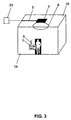
- Figure 3 shows the application of the present invention in public indoor environment such as airports, railway stations, department and convenient stores.
- this application relates to the wireless communication within a large hall 19.
- a fixed hub 2 connected to an information source by means of a connection line 5 is provided on the ceiling 16 of the hall 19.
- the user can communicate with the fixed hub 2 by means of the antenna 3 of the mobile terminal 1 of the user.
- the fixed hubs 2 being fixed axis stations for the communication are preferably public download servers (PDS).
- PDS public download servers
- the mobile terminals will be distinguished in so-called universal terminals (UT) and terminal with the reduced functionality (TRF).
- the fixed hubs and preferably the PDS units can be connected to a information source by different means:
- the PDS units are connected by means of a fixed connection 5 (for example a optical cable) to a broadband data highway 22, (for example an ATM fixed backbone) or a main information server 23 containing the source of information.
- a fixed connection 5 for example a optical cable
- a broadband data highway 22 for example an ATM fixed backbone
- main information server 23 containing the source of information.
- the PDS unit is connected by means of a point-to-point fixed wireless connection 6 to a broadband data highway 22 or a main information server 23 containing the source of information.
- the PDS unit is connected by a point-to-multipoint wireless local loop (WLL) connection to the broadband data highway 22 or a main information server 23 containing the source of information.
- WLL wireless local loop
- the fixed hub or PDS unit 2 contains a memory block (reference 20 in figure 1) which may be updated by placing a new (updated) memory block in the PDS unit by a service provider. This can be done for example by placing a memory stick with a large memory.
- the mobile terminals 1 generally have a narrow angle beam shape.
- the radiation beams of the antennas 4 of the fixed hubs 2 generally have linear or circular polarization.
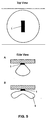
- Figure 4 shows PDS antenna diagram requirements for street applications.
- the radiation beam of the fixed hubs (PDS) 2 can be like alternatively shown in figures 4a and 4b in a top view, wherein the uniform coverage provided by the alternative according to figure 4b is preferred.
- the radiation beam according to the embodiment of figure 4b can be described as having a kidney like cross section when seen from above. Besides a uniform coverage this solution offers an extension of the communication range. Therefore, when using the alternative as shown in figure 4b for a larger communication distance the antenna gain is larger and for a smaller communication distance the antenna gain is smaller. This allows an optimization of the transmission power and therefore a reduction of the requirements on the AGC (autocratic gain control) of the receiver in the mobile terminal 1.
- AGC autocratic gain control
- Figure 5 shows PDS antenna diagram requirements for train, underground and/or large hall environments in which the public download server (PDS) is preferably placed on the ceiling.
- PDS public download server
- the radiation pattern having a top view according to figure 4b is preferred, as it offers uniform coverage solution and an extension of the communication range.
- the data rate for the communication of the PDS units with their information source may be smaller compared to the communication rate between the fixed hubs (PDS) and the mobile terminals or between two mobile terminals.
- the PDS unit can be only a video server or it is connected to a main video server and provides only content coming from the main video server.
- the mobile terminals 1 respectively have an antenna 3 providing a "pencil” like team shape (high gain antenna) with linear or circular polarization.
- the mobile terminal 1 can be provided with a camera 9, an optional front end for other wireless systems (for example bluetooth 21), a screen 10 capable of DV playback, a microphone 11, headphone sockets 12, a connection plug 13 for game joysticks, a touch screen 14 and a memory 15 able to store more than one full-time high-quality video.
- wireless systems for example bluetooth 21
- a screen 10 capable of DV playback
- a microphone 11 headphone sockets 12
- a connection plug 13 for game joysticks for game joysticks
- touch screen 14 able to store more than one full-time high-quality video.
- the antenna 3 can be integrated in a front end consisting of the highway antenna 3 and a RF front end.
- Additional integrated (or output to external) wireless connection radio front ends can be provided having an operation frequency lower than 60 GHz, whereby the operation frequency is not an intermediate frequency of the 60 GHz front end.
- FIG. 6 shows a mobile terminal 1 with maximum functionality. Furthermore, a terminal with reduced functionality (TRP) can be used.
- TRF has only content decoder, control units and man/machine interfaces as for example a portable MP3 player or a portable DVD player.
- the TRF may only have a control unit and a man/machine interface as for example a simple display or an earphone.
- the communication data rate is n - 100 Mbit/s, whereby n is an integer larger than 1.
- Lower data rate modes can also be provided especially in conjunction with the terminal with reduced functionality.
- the modulation schemes can be chosen arbitrarily as long as they can cope with very high data rates.
- the modulation scheme can be for example OFDM based and optionally the bandwidth is a multiple of the 20 MHz OFDM bandwidth.
- All fixed hubs and mobile terminals are optionally designed to have an intermediate frequency in the 5 GHz range (non-licensed and ISM industrial scientific medical band) to provide a dual frequency operation In the 5 GHz and 60 GHz range.
- all fixed hubs and mobile terminals are designed to have an intermediate frequency in the 2,4 GHz range (ISM band) to provide a- dual frequency operation in the 2,4 GHz and 60 GHz range.
- ISM band 2,4 GHz range
Landscapes
- Engineering & Computer Science (AREA)
- Computer Networks & Wireless Communication (AREA)
- Signal Processing (AREA)
- Mobile Radio Communication Systems (AREA)
Abstract
Description
- The present invention relates to a wireless transmission system operating in a 60 GHZ range which can be used for open public applications.
- The data rate demand for wireless systems is permanently growing due to the variety of now applications. To meet the increased demand of high data rate applications, a new generation of the wireless communication systems is targeted. Due to the common spectrum shortage, the natural way of looking at higher frequencies like those in higher microwave and lower millimeter-wave bands is recommended. Recently the spectrum in a 60 GHz range (a 59 to 64 GHz band) has been allocated for non-licensed applications worldwide. Other non licensed bands are for example the 2.4 GHz ISMband, the 5.8 GHz band and the 24 GHz band.
- Background information can be found in L. Fernandes, "Developing a System Concept and Technologies for Mobile Broadband Communications", IEEE Personal Communication Magazine, February 1995.
- The following European patent applications of Sony International (Europe) GmbH relate to technologies which can be applied for a transmission in said 60 GHz non-licensed frequency band:
- EP 0 969 602 A1 relating to a TX/RX structure for a dual frequency mode,
-
EP 1 006 668 Al relating also to a dual frequency band transceiver, - EP 0 889 543 Al relating to a wideband printed dipole antenna for microwave and millimeter-wave applications,
- EP 0 920 074 Al relating to a circular polarized planar printed antenna concept with shaped radiation pattern,
- EP 0 889 542 Al relating to a wideband printed phase array antenna for microwave and millimeter-wave applications.
- In view of the above-cited prior art it is the object of the present invention to propose a wireless transmission system designed for a transmission of data in the 60 GHz range tearing advantage from the fact that said 60 GHz range is a non-licensed frequency band and from the specific propagation properties (high attenuation, oxygen absorption).
- According to a first aspect of the present invention a wireless transmission system designed for the transmission of data in the 60 GHz range comprises a public download server connected to a network backbone or a main server and a mobile terminal provided with a narrow beam antenna.
- The communication range can be limited to 20 meters or less.
- The public download server can be connected to a broadband data highway and/or a main server by means of an optical cable.
- The public download server can be connected to a broadband data highway or a main server by means of a wireless point-to-point connection.
- The public download server can be connected to a broadband data highway or a main server by means of a point-to-multipoint wireless local loop connection.
- The public download server and the mobile terminal can be designed for a dual frequency operation, one transmission frequency being in the 60 GHz range and a second transmission frequency being an intermediate frequency in a range below the 60 GHz range,
- The public domain server can be provided with a wide angle beam antenna.
- The public domain server can be provided with an antenna having a kidney shaped beam in cross section.
- According to a further aspect of the present invention a wireless transmission system designed for the transmission of data in the 60 GHz range is proposed, the system comprising a teed hub provided with a wide angle beam antenna and a mobile terminal provided with a narrow beam antenna.
- According to a still further aspect of the present invention a wireless transmission system designed for the transmission of data in the 60 GHz range is provided, the system comprising at least two mobile terminals respectively provided with a narrow angle antenna for communication with each other.
- According to a still further aspect of the invention a wireless transmission system is proposed comprising a plurality of public access server and at least one mobile terminal, The mobile terminal is designed to upload/download content from the public access server by means of a wireless transmission and the public download server all operate with the same transmission frequency in a non-licensed frequency band.
- The communication between the mobile terminal and respectively a public access server is preferably free of charge. The uploading/downloading of content can be charged to the user of the mobile terminal.
- Preferably there is no hand-over between adjacent public access server.
- According to a still further aspect of the invention, a method for uploading and/or downloading content from a public access server to/from mobile terminals over an air interface is proposed. The air interface uses a non-licensed frequency band and the transmission itself is free of charge. The user of a mobile terminal is charged for uploading/downloading content. Preferably a service provider is owner of the public access server.
- The public access server can be installed in a large hall environment, in public vehicles, facing sidewalks, and/or at gas stations or traffic lights.
- Further advantages, features and objects of the present invention will become evident for the man skilled in the art when reading the following detailed description of embodiments taken in conjunction with the figures of the enclosed drawings.
- Figure 1 shows a 60 GHz public access system application scenario;
- Figure 2 shows a 60 GHz public access system application scenario applied for underground and trains;
- Figure 3 shows a 60 GHz public access system application scenario for large rooms (airport, train station, ...);
- Figure 4 shows public download server antenna diagram requirements for open public access applications (streets, etc.);
- Figure 5 shows public download server antenna diagram requirements for trains, underground and large room environments; and
- Figure 6 shows a universal terminal as one embodiment of a mobile terminal according to the present invention.
- With reference to figures 1, 2 and 3 different environmental scenarios for the application of the present invention will be explained.
- Generally the present invention is targeting solutions for urban areas like town environments shown in figure 1. Users having a
mobile terminal 1 can communicate by means of a wireless transmission in the 60 GHz range and optionally other ranges below said 60 GHz range withfixed hubs 2. Thefixed hubs 2 are public access server. Furthermore, twomobile terminals 1 can communicate with each other in the 60 GHz range for example to perform wireless games. - The communication of a
mobile terminal 1 with thefixed hub 2 can be used, for example for a fast downloading of video within a short time period on a storage unit (for example hard disc) within themobile terminal 1. Alternatively, contents of news information centers can be downloaded or video e-mail can be exchanged with thefixed hub 2. - Note that the
fixed hubs 2 are respectively linked to an information source such as a broadband data highway 22 (for example a ATM fixed backbone) or amain information server 23 by means of a fixed connection S or awireless transmission 6. Note that themobile terminals 1 are respectively provided with an antenna means 3 with a narrow shaped beam. Thefixed hubs 2 are respectively provided with an antenna d having a. wide angle beam shape. The communication range between respectively afixed hub 2 and amobile terminal 1 or between twomobile terminals 1 is for example about 20 meters maximum. - Figure 2 shows the application of a wireless transmission system according to the present invention in public transportation means such as underground or trains. On the
ceiling 16 of awagon 17 fixedhubs 2 are provided. These hubs are respectively connected by means of a connection line S to acentral data server 7. Users within thewagon 17 having amobile terminal 1 can communicate, with thefixed hubs 2 while commuting in thewagon 17. Furthermore agateway 8 having an interface fimction is provided which is connected to thecentral data server 7 of thewagon 17 and which serves for updating the content of thecentral data server 7. - Figure 3 shows the application of the present invention in public indoor environment such as airports, railway stations, department and convenient stores. Generally this application relates to the wireless communication within a large hall 19. Again, a
fixed hub 2 connected to an information source by means of aconnection line 5 is provided on theceiling 16 of the hall 19. The user can communicate with thefixed hub 2 by means of theantenna 3 of themobile terminal 1 of the user. - The
fixed hubs 2 being fixed axis stations for the communication are preferably public download servers (PDS). The mobile terminals will be distinguished in so-called universal terminals (UT) and terminal with the reduced functionality (TRF). - The fixed hubs and preferably the PDS units can be connected to a information source by different means:
- According to a first alternative the PDS units are connected by means of a fixed connection 5 (for example a optical cable) to a
broadband data highway 22, (for example an ATM fixed backbone) or amain information server 23 containing the source of information. - According to a second alternative the PDS unit is connected by means of a point-to-point fixed
wireless connection 6 to abroadband data highway 22 or amain information server 23 containing the source of information. - According to a still further alternative the PDS unit is connected by a point-to-multipoint wireless local loop (WLL) connection to the
broadband data highway 22 or amain information server 23 containing the source of information. - The fixed hub or
PDS unit 2 contains a memory block (reference 20 in figure 1) which may be updated by placing a new (updated) memory block in the PDS unit by a service provider. This can be done for example by placing a memory stick with a large memory. - With reference to figures 4 and 5 the wide angle radiation beam of the
antennas 4 of the fixedhubs 2 will be explained. Themobile terminals 1 generally have a narrow angle beam shape. - The radiation beams of the
antennas 4 of the fixedhubs 2 generally have linear or circular polarization. - Figure 4 shows PDS antenna diagram requirements for street applications. For this scenario the radiation beam of the fixed hubs (PDS) 2 can be like alternatively shown in figures 4a and 4b in a top view, wherein the uniform coverage provided by the alternative according to figure 4b is preferred. The radiation beam according to the embodiment of figure 4b can be described as having a kidney like cross section when seen from above. Besides a uniform coverage this solution offers an extension of the communication range. Therefore, when using the alternative as shown in figure 4b for a larger communication distance the antenna gain is larger and for a smaller communication distance the antenna gain is smaller. This allows an optimization of the transmission power and therefore a reduction of the requirements on the AGC (autocratic gain control) of the receiver in the
mobile terminal 1. - Figure 5 shows PDS antenna diagram requirements for train, underground and/or large hall environments in which the public download server (PDS) is preferably placed on the ceiling. Preferably the radiation pattern having a top view according to figure 4b is preferred, as it offers uniform coverage solution and an extension of the communication range.
- The data rate for the communication of the PDS units with their information source (data highway or main server) may be smaller compared to the communication rate between the fixed hubs (PDS) and the mobile terminals or between two mobile terminals. Optionally the PDS unit can be only a video server or it is connected to a main video server and provides only content coming from the main video server.
- With reference to figure 6 a
mobile terminal 1 according to the present invention will be explained. Themobile terminals 1 respectively have anantenna 3 providing a "pencil" like team shape (high gain antenna) with linear or circular polarization. - The
mobile terminal 1 can be provided with a camera 9, an optional front end for other wireless systems (for example bluetooth 21), ascreen 10 capable of DV playback, amicrophone 11,headphone sockets 12, aconnection plug 13 for game joysticks, atouch screen 14 and amemory 15 able to store more than one full-time high-quality video. - The
antenna 3 can be integrated in a front end consisting of thehighway antenna 3 and a RF front end. - Additional integrated (or output to external) wireless connection radio front ends can be provided having an operation frequency lower than 60 GHz, whereby the operation frequency is not an intermediate frequency of the 60 GHz front end.
- Figure 6 shows a
mobile terminal 1 with maximum functionality. Furthermore, a terminal with reduced functionality (TRP) can be used. A TRF has only content decoder, control units and man/machine interfaces as for example a portable MP3 player or a portable DVD player. As a further alternative the TRF may only have a control unit and a man/machine interface as for example a simple display or an earphone. - The communication data rate between a PDS unit and a mobile terminal and between two mobile terminals, respectively, exceeds 50 Mbit/s (user data rate) and is preferably larger than 100 Mbit/s. In an ideal case the communication data rate is n - 100 Mbit/s, whereby n is an integer larger than 1. Lower data rate modes can also be provided especially in conjunction with the terminal with reduced functionality.
- Both TDMA and FTMA access is allowed. The modulation schemes can be chosen arbitrarily as long as they can cope with very high data rates. The modulation scheme can be for example OFDM based and optionally the bandwidth is a multiple of the 20 MHz OFDM bandwidth.
- All fixed hubs and mobile terminals are optionally designed to have an intermediate frequency in the 5 GHz range (non-licensed and ISM industrial scientific medical band) to provide a dual frequency operation In the 5 GHz and 60 GHz range.
- Optionally all fixed hubs and mobile terminals are designed to have an intermediate frequency in the 2,4 GHz range (ISM band) to provide a- dual frequency operation in the 2,4 GHz and 60 GHz range.
- Communication protocol requirements between PDS and UT (or TRF), or between UT (or TRF) and other UT (or TRF):
- has LESS complexity compared to classic WLAN protocols, or classic Cellular system protocols,
- it may allowed only simple download in restricted operation scenario,
- they do not necessarily support handover,
- they are not necessarily the same as communication protocols between the PDS unit and data highway or main data server, and by the rule they have less complexity,
- PDS unit may have a means to terminate more complex communication protocol between PDS and data highway and communicate with BUT (or TRF) by the simpler protocol definition,
- Optionally, protocol between PDS and UT (or TRF) supports MPEG streaming all more than one MPEG standard,
- Optionally protocol stack between PDS and UT (or TRF) supports IP.
-
- 1. Advantages of the proposed public systems are:
- usage of the non-licensed band in 59-64 GHz range offering, a large spectrum and very large data rates, they are not available to provide to the users,
- due to the non-licensed band, there is no need to pay operation licenses locally, so that everyone may be operator, and cover those areas, which are for operate consider as profitable, mainly only common standard,
- due to very large data rates available a new prospective of applications are opened which are fully complementary to so-called 3G and 4G mobile communication systems, so proposed systems may be considered as a new business opportunity, also for those companies making 2G, 3 G and in future 4G business.
- due to the large frequency of the operation the total front end size and antenna size may be very small and very easy to be integrated in various types of terminals: * beginning from current PDA types -of terminals, through so-called 2G and 3G to the future UT (or TRF) terminal,
- due to the large frequency and large attenuation, small transmission power, and specified UT antenna pattern, as well as large oxygen absorption frequency RE-USE may be easily adopted, so there is almost unlimited possibility of providing very large wireless data rates in very small environments, Density and Capacity of the system is almost unlimited, in contrast to so-called 3G and future 4G systems.
- proposed concept does not need to have smart backbone infrastructure like cellular systems, it is much more simpler, there is no handover between different fixed hubs and the same transmission frequency can be reused efficiently,
- proposed concept has much lower complexity compared to the WLAN (wireless local area network) approach.
- The basic business related ideas are:
- a) wireless communication access is free of charge,
- b) payment only for specific content (e.g. video, audio, newspapers, game downloading, gaming),
- c) the key operation mode is downloading,
- d) sending and receiving private information (E-mails, video E-mails, documents, profiles) is in principle free of charge,
- e) gaming from one UT to another UT, as well as gaming from, UT with PDS Is free of charge,
- f) some charges may be applied for real time, delay sensitive, applications like video and audio telephony,
-
- a) User downloads a high quality video content from PDS within couple of minutes (data rates larger than 100 Mbit/s). The data is memorized on the memory entity (e. g. miniature hard disc or future memory stick), which is placed within the UT terminal, After that the user may playback the content where he wants, and in time he wants, independently from further wireless access availability. The payment of the content goes by personal identification process via scrambled information sent by UT to PSD.
- b) A user passes near the PSD and pickup in walking by pressing the button at UT, within the seconds wanted newspaper or magazine, and read it where he wants, and when he wants, independently from further wireless access availability. The payment of the content goes by, personal identification process via scrambled information sent by UT to PSD.
- c) Sitting in the underground user downloads (payment obliged) content he wants, but in the same time he may chose one of a plurality of free of charge contents provided by the underground service company. Underground service company will have satisfied users, and take a payment for advertisement. Advertisement is included in free of charge content.
- d) User passes near the PSD and pickup in walking by pressing the button at UT, (within the seconds) his personal information content. For example he takes all E-mails, or Video/Audio E-mail. or documents sent to him. In the same time by pressing the button he sends to PSD his E-mails, video E-mails or other content to PSD. PSD takes this information and sends it further via internet. This service is free of charge, but make a majority of people interested to purchase UT, and after that to take a proprietary content by
wireless 60 GHz system. - e) User stands in front of PSD and make a classic audio or video telephony using UT, which is through fast internet connection further in real time provided to the addressed user. This service is not free of charge, but make a direct competition to mobile network service providers (3G). Due to the lower system cost and no infrastructure in background, the final price may be highly competitive.
- f) User has UT with play station capability and perform gaming against the PSD server during traveling by underground, by means of wireless. This service may be in underground or in train free of charge, but on the street or waiting in airport hall it may be charged.
- g) User has UT with play station capability and play against other user having UT with play station capability by
wireless 60 GHz broadband link. This service is free of charge. - h) User has UT and standing close to PSD is downloading internet information during waiting for his bus. This service is free of charge.
- i) User is driving the car and during waiting for the green light he is downloading content of the interest, by using 60 GHz communications
- j) User is driving through "Drive-In" restaurant or fuel tank station and during the waiting time for obtaining services, he is connecting to 60 GHz PDS and picks up specific content.
- k) During a visit to the general store or airport (large indoor environment with public access) user takes content from 60 GHz PDS unit Large store and for example airport axe offering free of charge navigation service for their environments and entertainment program.' Content provided for user may be also free of charge, but aligned with commercials, coming from owner of the PSD unit.
- l) By giving to user free of charge UT or TRF, to obtain only selected (limited by provider of the free terminal) content,
- m) While buying some snacks in small 24-hours convenience store, user picks up some information / entertainment content (using 60 GHz means) from indoor PDS unit to his UT or TRF.
Claims (6)
- Wireless transmission system designed for the transmission of data in the 60 GHz range,
the system comprising:- a public download server connected to an information source, the public download server comprising a first antenna, and- a mobile terminal comprising a second antenna being a narrow beam antenna,
wherein the public download server and the mobile terminal are adapted for communication by means of a wireless transmission in the 60 GHz range via said first and second antennas,
characterized in that
the public download server is provided with an antenna with a kidney shaped beam in cross-section. - System according to claim 1,
characterized in that
the communication range is 20 meters or less. - System according to one of the preceding claims,
characterized in that
the public download server and the mobile terminal are designed for a dual frequency operation, one transmission frequency being the 60 GHz range and a second transmission frequency being an intermediate frequency below the 60 GHz range. - System according to one of the preceding claims,
characterized in that
the public download server and the mobile terminal are designed exclusively for uploading/downloading content from the public download server to the mobile terminal. - Method for uploading and/or downloading content from a public access server having a first antenna to/from mobile terminals over an air interface,
wherein each mobile terminal has a second antenna and the air interface uses a 60 GHz non-licensed frequency band,
characterized in that
transmission between the public access server and the mobile terminals is performed via a narrow beam antenna of the respective mobile terminal and via an antenna of the public download server that has a kidney shaped beam in cross-section. - Method according to claim 5,
characterized in that
the public access server is installed in a large hall environment or in public vehicles or facing sidewalks or at gas stations or at traffic lights.
Applications Claiming Priority (2)
| Application Number | Priority Date | Filing Date | Title |
|---|---|---|---|
| US09/593,178 US7142812B1 (en) | 2000-06-13 | 2000-06-13 | Wireless transmission system |
| EP01942172A EP1319274A4 (en) | 2000-06-13 | 2001-06-11 | WIRELESS TRANSMISSION SYSTEM |
Related Parent Applications (1)
| Application Number | Title | Priority Date | Filing Date |
|---|---|---|---|
| EP01942172A Division EP1319274A4 (en) | 2000-06-13 | 2001-06-11 | WIRELESS TRANSMISSION SYSTEM |
Publications (2)
| Publication Number | Publication Date |
|---|---|
| EP1626536A2 true EP1626536A2 (en) | 2006-02-15 |
| EP1626536A3 EP1626536A3 (en) | 2006-05-10 |
Family
ID=24373704
Family Applications (2)
| Application Number | Title | Priority Date | Filing Date |
|---|---|---|---|
| EP01942172A Withdrawn EP1319274A4 (en) | 2000-06-13 | 2001-06-11 | WIRELESS TRANSMISSION SYSTEM |
| EP05024428A Ceased EP1626536A3 (en) | 2000-06-13 | 2001-06-11 | Wireless transmission system |
Family Applications Before (1)
| Application Number | Title | Priority Date | Filing Date |
|---|---|---|---|
| EP01942172A Withdrawn EP1319274A4 (en) | 2000-06-13 | 2001-06-11 | WIRELESS TRANSMISSION SYSTEM |
Country Status (5)
| Country | Link |
|---|---|
| US (1) | US7142812B1 (en) |
| EP (2) | EP1319274A4 (en) |
| KR (1) | KR20030007963A (en) |
| AU (1) | AU2001275460A1 (en) |
| WO (1) | WO2001097433A2 (en) |
Cited By (3)
| Publication number | Priority date | Publication date | Assignee | Title |
|---|---|---|---|---|
| US7941139B2 (en) | 2006-07-05 | 2011-05-10 | Airbus Deutschland Gmbh | Method and apparatus for the transmission of data |
| EP2339519A1 (en) * | 2009-12-22 | 2011-06-29 | NCR Corporation | Method and system for delivering multi-media products |
| EP2428908A1 (en) * | 2010-09-14 | 2012-03-14 | NCR Corporation | Multi-media content at a digital download kiosk |
Families Citing this family (23)
| Publication number | Priority date | Publication date | Assignee | Title |
|---|---|---|---|---|
| AU2002231427A1 (en) | 2000-08-16 | 2002-02-25 | The Boeing Company | Method and apparatus for providing bi-directional data services and live television programming to mobile platforms |
| US7921442B2 (en) | 2000-08-16 | 2011-04-05 | The Boeing Company | Method and apparatus for simultaneous live television and data services using single beam antennas |
| WO2002033610A1 (en) * | 2000-10-17 | 2002-04-25 | Ishii, Mieko | Personal information protective method, personal information protective system, processing device, portable transmitter/receiver, and program |
| US6990338B2 (en) | 2001-06-11 | 2006-01-24 | The Boeing Company | Mobile wireless local area network and related methods |
| US7555287B1 (en) | 2001-11-01 | 2009-06-30 | Nokia Corporation | Customized messaging between wireless access point and services |
| US20030110046A1 (en) * | 2001-12-06 | 2003-06-12 | Nokia Corporation | Method and device for dispensing electronic information |
| US6947772B2 (en) * | 2002-01-31 | 2005-09-20 | Qualcomm Incorporated | System and method for providing messages on a wireless device connecting to an application server |
| US7340214B1 (en) | 2002-02-13 | 2008-03-04 | Nokia Corporation | Short-range wireless system and method for multimedia tags |
| DE10207858A1 (en) | 2002-02-19 | 2003-08-28 | Deutsche Telekom Ag | Method and system for the provision of information and communication in vehicles |
| US7102640B1 (en) | 2002-03-21 | 2006-09-05 | Nokia Corporation | Service/device indication with graphical interface |
| US7039398B2 (en) | 2002-08-30 | 2006-05-02 | Qualcomm Incorporated | Server processing of interactive screens for a wireless device |
| US6996394B2 (en) | 2002-08-30 | 2006-02-07 | Qualcomm Incorporated | Server processing in providing messages for a wireless device connecting to a server |
| US7769398B2 (en) * | 2002-11-15 | 2010-08-03 | The Boeing Company | Broadband wireless distribution system for mobile platform interior |
| US7751337B2 (en) | 2003-02-10 | 2010-07-06 | The Boeing Company | Method and apparatus for optimizing forward link data rate for radio frequency transmissions to mobile platforms |
| US7020121B2 (en) * | 2003-11-17 | 2006-03-28 | Sony Corporation | Method and system for wireless digital multimedia transmission |
| US7860497B2 (en) | 2004-03-31 | 2010-12-28 | The Boeing Company | Dynamic configuration management |
| KR100876554B1 (en) * | 2006-12-07 | 2008-12-31 | 한국전자통신연구원 | Multiple access system and method using wireless communication |
| US20080182513A1 (en) * | 2007-01-29 | 2008-07-31 | Hassan Amer A | High Frequency Communications |
| US8041333B2 (en) | 2007-06-14 | 2011-10-18 | Broadcom Corporation | Method and system for 60 GHz antenna adaptation and user coordination based on base station beacons |
| US9538138B2 (en) | 2013-06-05 | 2017-01-03 | Puddle Innovations | System for providing access to shared multimedia content |
| US20200094761A1 (en) * | 2018-09-24 | 2020-03-26 | Novelic D.O.O. | Seat occupation, vital signs and safety belt lock sensor system for rear vehicle seats without power supply |
| US12041589B2 (en) * | 2020-08-17 | 2024-07-16 | Charter Communications Operating, Llc | Methods and apparatus for spectrum utilization coordination between wireline backhaul and wireless systems |
| US11563593B2 (en) | 2020-08-19 | 2023-01-24 | Charter Communications Operating, Llc | Methods and apparatus for coordination between wireline backhaul and wireless systems |
Family Cites Families (21)
| Publication number | Priority date | Publication date | Assignee | Title |
|---|---|---|---|---|
| US4414550A (en) * | 1981-08-04 | 1983-11-08 | The Bendix Corporation | Low profile circular array antenna and microstrip elements therefor |
| USH288H (en) * | 1983-07-25 | 1987-06-02 | The United States Of America As Represented By The Secretary Of The Army | Interference cancelling transmitter |
| US4940990A (en) * | 1989-01-19 | 1990-07-10 | University Of British Columbia | Intrabuilding wireless communication system |
| US6002918A (en) * | 1989-06-29 | 1999-12-14 | Symbol Technologies, Inc. | Power-saving arrangement and method for mobile units in communications network |
| JPH06508970A (en) * | 1991-07-01 | 1994-10-06 | モトローラ・インコーポレイテッド | Personal communication system providing auxiliary information mode |
| FR2699026A1 (en) * | 1992-12-09 | 1994-06-10 | Trt Telecom Radio Electr | Transmission system for transmitting information at different rates and transmission station suitable for such a system. |
| GB9226707D0 (en) * | 1992-12-22 | 1993-02-17 | Ncr Int Inc | Wireless local area network system with mobile station handover |
| EP0692840A1 (en) * | 1994-07-11 | 1996-01-17 | Nippon Paint Co., Ltd. | Wide bandwidth electromagnetic wave absorbing material |
| US5909652A (en) * | 1995-04-18 | 1999-06-01 | Casio Computer Co., Ltd. | Radio communication system and radio communication terminal |
| US5835061A (en) * | 1995-06-06 | 1998-11-10 | Wayport, Inc. | Method and apparatus for geographic-based communications service |
| US6341133B1 (en) * | 1995-10-11 | 2002-01-22 | Sony Corporation | Information providing apparatus and portable communication terminal |
| JP3005937B2 (en) * | 1996-02-28 | 2000-02-07 | 日本電気株式会社 | Private communication equipment |
| EP0818749A3 (en) * | 1996-07-12 | 1999-05-12 | Jürgen Dethloff | Method and system for data protection |
| US5978650A (en) * | 1997-01-21 | 1999-11-02 | Adc Telecommunications, Inc. | System and method for transmitting data |
| SE509278C2 (en) * | 1997-05-07 | 1999-01-11 | Ericsson Telefon Ab L M | Radio antenna device and method for simultaneous generation of wide lobe and narrow point lobe |
| US5842130A (en) * | 1997-05-29 | 1998-11-24 | Motorola, Inc. | Method for identifying a mobile unit in a wireless communication system |
| DE19722547A1 (en) * | 1997-05-30 | 1998-12-03 | Bosch Gmbh Robert | Antenna for radiating high-frequency radio signals |
| US6349217B1 (en) * | 1998-04-24 | 2002-02-19 | Lucent Technologies Inc. | Multi-mode/multi-rate fixed wireless communication system |
| FR2779022B1 (en) * | 1998-05-20 | 2000-07-28 | Nortel Matra Cellular | RADIOCOMMUNICATION BASE STATION |
| JP2000069541A (en) * | 1998-08-26 | 2000-03-03 | Mitsubishi Electric Corp | Mobile communication system |
| US6326926B1 (en) * | 2000-05-18 | 2001-12-04 | Telxon Corporation | Method of operating a wireless and a short-range wireless connection in the same frequency |
-
2000
- 2000-06-13 US US09/593,178 patent/US7142812B1/en not_active Expired - Lifetime
-
2001
- 2001-06-11 EP EP01942172A patent/EP1319274A4/en not_active Withdrawn
- 2001-06-11 EP EP05024428A patent/EP1626536A3/en not_active Ceased
- 2001-06-11 KR KR1020027016999A patent/KR20030007963A/en not_active Withdrawn
- 2001-06-11 AU AU2001275460A patent/AU2001275460A1/en not_active Abandoned
- 2001-06-11 WO PCT/US2001/018806 patent/WO2001097433A2/en not_active Ceased
Cited By (4)
| Publication number | Priority date | Publication date | Assignee | Title |
|---|---|---|---|---|
| US7941139B2 (en) | 2006-07-05 | 2011-05-10 | Airbus Deutschland Gmbh | Method and apparatus for the transmission of data |
| EP2339519A1 (en) * | 2009-12-22 | 2011-06-29 | NCR Corporation | Method and system for delivering multi-media products |
| EP2428908A1 (en) * | 2010-09-14 | 2012-03-14 | NCR Corporation | Multi-media content at a digital download kiosk |
| US10296726B2 (en) | 2010-09-14 | 2019-05-21 | Ncr Corporation | Multi-media content at a digital download kiosk |
Also Published As
| Publication number | Publication date |
|---|---|
| KR20030007963A (en) | 2003-01-23 |
| EP1319274A4 (en) | 2004-01-02 |
| EP1319274A2 (en) | 2003-06-18 |
| WO2001097433A2 (en) | 2001-12-20 |
| AU2001275460A1 (en) | 2001-12-24 |
| EP1626536A3 (en) | 2006-05-10 |
| WO2001097433A3 (en) | 2002-07-18 |
| US7142812B1 (en) | 2006-11-28 |
Similar Documents
| Publication | Publication Date | Title |
|---|---|---|
| US7142812B1 (en) | Wireless transmission system | |
| Hills et al. | Seamless access to multiple wireless data networks. A wireless data network infrastructure at Carnegie Mellon University | |
| US6944402B1 (en) | Extended range infrared communication (ERIC) for an infrared associated (IrDA) compliant portable device | |
| US7710932B2 (en) | Method and apparatus for encouraging routing in a network | |
| KR101541676B1 (en) | Portable electronic device with proximity-based content synchronization | |
| EP1260042B1 (en) | Data distribution system and method | |
| JP2004523970A5 (en) | ||
| JP2004523970A (en) | Beacons for providing information services | |
| EP1363456A2 (en) | Video-on-demand service system and method of dynamic image distribution | |
| Schrick et al. | Wireless broadband in a box | |
| CN104093036A (en) | Method and device for cross-layer optimization in multimedia communication with different user terminals | |
| Stirling | Mobile multimedia platforms | |
| JP2004528750A (en) | Improved mobile telephone network and device | |
| US20060229980A1 (en) | Payment system and method for data broadcasted from a remote location to vehicles | |
| US8185645B2 (en) | Content delivery system using wireless portable terminal and delivery method therefor | |
| Brewer | Technology insights for rural connectivity | |
| Mannings et al. | Wireless everything-unwiring the world | |
| KR20060121508A (en) | Method and system for providing mobile communication terminal DMX service using short-range wireless communication | |
| Narenthiran et al. | S-DMB system architecture and the MODIS DEMO | |
| Godwin-Jones | Wireless networks | |
| Biesecker | Broadband Wireless, Integrated Services and Their Application to Intelligent Transportation Systems | |
| Gozalvez | HSDPA goes commercial | |
| CN107153981A (en) | Mobile rental device | |
| Huy et al. | Reference scenario specification: final description | |
| Kush | Wireless Media: A New Paradigm |
Legal Events
| Date | Code | Title | Description |
|---|---|---|---|
| PUAI | Public reference made under article 153(3) epc to a published international application that has entered the european phase |
Free format text: ORIGINAL CODE: 0009012 |
|
| AC | Divisional application: reference to earlier application |
Ref document number: 1319274 Country of ref document: EP Kind code of ref document: P |
|
| AK | Designated contracting states |
Kind code of ref document: A2 Designated state(s): AT BE CH CY DE DK ES FI FR GB GR IE IT LI LU MC NL PT SE TR |
|
| AX | Request for extension of the european patent |
Extension state: AL |
|
| PUAL | Search report despatched |
Free format text: ORIGINAL CODE: 0009013 |
|
| RIN1 | Information on inventor provided before grant (corrected) |
Inventor name: KAWASAKI, KENICHI Inventor name: FUKUZAWA, KEIJI Inventor name: SASAKI, KAZUJI Inventor name: BRANKOVIC, VESELIN STUTTGART TECHNOLOGY CENTER Inventor name: AMIR-ALIKHANI Inventor name: RATNI, MOHAMED Inventor name: KRUPEZEVIC, DRAGEN |
|
| AK | Designated contracting states |
Kind code of ref document: A3 Designated state(s): AT BE CH CY DE DK ES FI FR GB GR IE IT LI LU MC NL PT SE TR |
|
| AX | Request for extension of the european patent |
Extension state: AL |
|
| RIC1 | Information provided on ipc code assigned before grant |
Ipc: H01Q 1/24 20060101ALI20060322BHEP Ipc: H01Q 1/00 20060101ALI20060322BHEP Ipc: H04L 12/56 20060101ALI20060322BHEP Ipc: H04L 12/28 20060101AFI20051222BHEP |
|
| 17P | Request for examination filed |
Effective date: 20060607 |
|
| 17Q | First examination report despatched |
Effective date: 20060706 |
|
| AKX | Designation fees paid |
Designated state(s): DE FR GB |
|
| APBN | Date of receipt of notice of appeal recorded |
Free format text: ORIGINAL CODE: EPIDOSNNOA2E |
|
| APBR | Date of receipt of statement of grounds of appeal recorded |
Free format text: ORIGINAL CODE: EPIDOSNNOA3E |
|
| APAF | Appeal reference modified |
Free format text: ORIGINAL CODE: EPIDOSCREFNE |
|
| APBT | Appeal procedure closed |
Free format text: ORIGINAL CODE: EPIDOSNNOA9E |
|
| STAA | Information on the status of an ep patent application or granted ep patent |
Free format text: STATUS: THE APPLICATION HAS BEEN REFUSED |
|
| 18R | Application refused |
Effective date: 20110329 |