EP1626287A1 - Technique for estimating signal arrival direction not by utilizing eigenvalue decomposition and reception beam shaper - Google Patents
Technique for estimating signal arrival direction not by utilizing eigenvalue decomposition and reception beam shaper Download PDFInfo
- Publication number
- EP1626287A1 EP1626287A1 EP03730586A EP03730586A EP1626287A1 EP 1626287 A1 EP1626287 A1 EP 1626287A1 EP 03730586 A EP03730586 A EP 03730586A EP 03730586 A EP03730586 A EP 03730586A EP 1626287 A1 EP1626287 A1 EP 1626287A1
- Authority
- EP
- European Patent Office
- Prior art keywords
- arrival direction
- estimating
- signal arrival
- correlation matrix
- correlation
- Prior art date
- Legal status (The legal status is an assumption and is not a legal conclusion. Google has not performed a legal analysis and makes no representation as to the accuracy of the status listed.)
- Withdrawn
Links
Images




Classifications
-
- G—PHYSICS
- G01—MEASURING; TESTING
- G01S—RADIO DIRECTION-FINDING; RADIO NAVIGATION; DETERMINING DISTANCE OR VELOCITY BY USE OF RADIO WAVES; LOCATING OR PRESENCE-DETECTING BY USE OF THE REFLECTION OR RERADIATION OF RADIO WAVES; ANALOGOUS ARRANGEMENTS USING OTHER WAVES
- G01S3/00—Direction-finders for determining the direction from which infrasonic, sonic, ultrasonic or electromagnetic waves, or particle emission, not having a directional significance, are being received
- G01S3/02—Direction-finders for determining the direction from which infrasonic, sonic, ultrasonic or electromagnetic waves, or particle emission, not having a directional significance, are being received using radio waves
- G01S3/74—Multi-channel systems specially adapted for direction-finding, i.e. having a single antenna system capable of giving simultaneous indications of the directions of different signals
-
- G—PHYSICS
- G01—MEASURING; TESTING
- G01S—RADIO DIRECTION-FINDING; RADIO NAVIGATION; DETERMINING DISTANCE OR VELOCITY BY USE OF RADIO WAVES; LOCATING OR PRESENCE-DETECTING BY USE OF THE REFLECTION OR RERADIATION OF RADIO WAVES; ANALOGOUS ARRANGEMENTS USING OTHER WAVES
- G01S3/00—Direction-finders for determining the direction from which infrasonic, sonic, ultrasonic or electromagnetic waves, or particle emission, not having a directional significance, are being received
- G01S3/02—Direction-finders for determining the direction from which infrasonic, sonic, ultrasonic or electromagnetic waves, or particle emission, not having a directional significance, are being received using radio waves
- G01S3/14—Systems for determining direction or deviation from predetermined direction
- G01S3/46—Systems for determining direction or deviation from predetermined direction using antennas spaced apart and measuring phase or time difference between signals therefrom, i.e. path-difference systems
Definitions
- the present invention relates to a radio wave arrival direction estimating device for a base station which estimates a radio waves arrival direction with high accuracy by using an array antenna, and to a variable directivity receiving/transmitting device for a base station which varies the directivity of beam of an antenna based on the estimation of the arrival direction by the radio wave arrival direction estimating device.
- the present invention is of a technique by which an arrival direction of each of a plurality of incident signals (signals which are not uncorrelated to one another, or the multipath waves which are perfectly correlated) are estimated by means which is effective in calculation, and is especially a technique for estimating the arrival direction of each of the incident waves with similar incident directions with a high accuracy even when the length of received data is not sufficient and when the SNR is low.
- adaptive array antenna for mobile communications
- a plurality of antenna elements is arrayed in a shape and in different spatial positions.
- a technique for estimating an arrival direction of each of the radio waves incident at an antenna (referred to also as a signal, from the view point of signal processing) is thought to be an important elemental technique for an adaptive array antenna.
- a technique for estimating the arrival direction of each of the signals a subspace-based method which utilizes the orthogonality between a signal subspace and a noise subspace is well known from the view point of the estimation accuracy and the computation amount.
- a conventional subspace-based method requires processes such as Eigenvalue decomposition (EVD) of an array covariance matrix, singular value decomposition (SVD) of an array data matrix or the like in order to obtain a signal subspace (or a noise subspace).
- EMD Eigenvalue decomposition
- SVD singular value decomposition
- the calculation process for the eigenvalue decomposition (or the singular value decomposition) becomes complex so that much time is required for the calculation.
- the subspace-base method utilizing the orthogonality between a signal subspace and a noise subspace is well known from the view point of the complexity of calculation, the accuracy of estimation and the like.
- MUSIC Multiple signal classification
- the subspace-based method with spatial smoothing is well known.
- an array covariance matrix from signals incident on an array antenna is obtained so that a signal subspace and a noise subspace are obtained by the eigenvalue decomposition of the array covariance matrix. Then, the arrival direction of each of the signals is estimated by utilizing the orthogonality between the signal subspace and the noise subspace.
- a uniform linear array (ULA) is divided into subarrays in order to suppress the correlation of incident signals and the dimension of the signal subspace of the spatially averaged covariance matrix is recovered into the number of the multipath waves by conducting an averaging operation on the covariance matrix of each subarray. Accordingly, the estimation of the arrival direction of each of the correlated signals is realized by utilizing the orthogonality between the signal subspace and the noise subspace similarly to the conventional subspace-based method.
- A [ a ( ⁇ 1 ), a ( ⁇ 2 ), ⁇ , a ( ⁇ p )]
- a ( ⁇ k ) [1, e j ⁇ 0 r ( ⁇ r ) , ⁇ , e j ⁇ 0 ( M -1) ⁇ ( ⁇ t ) ] r
- s ( n ) [ s 1 ( n ), s 2 ( n ), ⁇ , s
- f 0 is a frequency of a carrier wave
- c is a propagation speed
- d is element spacing (a half-wavelength).
- T means a transpose
- a( ⁇ k ) and A are respectively a response vector and a response matrix of an array.
- w i (n) is white Gaussian noise which is independent among elements and has the average value of zero and whose electric power is ⁇ 2 .
- E ⁇ • ⁇ and (•) H respectively express an expectation value operation and a complex conjugate transpose
- R s E ⁇ s (n) s H (n) ⁇ is the covariance matrix of an incident multipath wave
- I M is an M ⁇ M unit matrix.
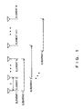
- Fig. 1 explains the dividing of the uniform linear array into subarrays.
- the entire uniform linear array is divided into L overlapped subarrays including m elements (where 1 ⁇ m ⁇ M) as shown in Fig. 1.
- a m ( ⁇ k ) and A m are respectively a response vector and a response matrix of a subarray.
- the covariance matrix of the first subarray can be expressed by formula 5 as below.
- formula 6 by spatially averaging the covariance matrixes ⁇ R i ⁇ of L subarrays.
- the space spanned by the signal vector ⁇ e 1 , e 2 , ??, e p ⁇ is called the signal subspace
- the space spanned by the noise vector ⁇ e p+1 , e p+2 , ising, e m ⁇ is called the noise subspace.
- the signal subspace can be expressed by using the response vector of the array.
- a method for estimating an arrival direction based on the orthogonality between the signal subspace and the noise subspace is called a subspace-based method.
- the subspace-based method for estimating the arrival direction such as the (spatial smoothing based) MUSIC requires the eigenvalue decomposition of the array covariance matrix in order to obtain the signal subspace or the noise subspace.
- the calculation process for the eigenvalue decomposition becomes complex so that much time is required for the calculation. Accordingly, the performance of the conventional subspace-based method for estimating the arrival direction based on the eigenvalue decomposition in the actual application is restricted by the processing time for the eigenvalue decomposition process because of the load of the calculation. Further, if the estimation of the arrival direction of each of the signals incident on the array is not realized quickly and accurately, the received/transmitted beam of the base station cannot be shaped accurately, and also, the performance of the receiving and transmitting system of the base station is impaired.
- a method for estimating signal arrival direction comprises a step of obtaining correlations among the data of some of the elements based on received signals from a plurality of array antenna elements which are linearly arrayed in different spatial positions with uniform element spacing, and defining one correlation matrix from the correlations, a step of estimating a noise subspace from the correlation matrix by a linear operation, and an estimation step of calculating a peak position of the spatial spectrum obtained from the noise subspace or a zero-point of a polynomial which is equivalent to the peak position, and calculating a signal arrival direction.
- the correlation matrix utilizes only the correlation among some antenna elements, so that the large amount of data as in the case of handling the correlation among all of the antenna elements does not have to be handled. Further, the eigenvalue decomposition is not performed so that the computational amount is reduced. Therefore the present invention can provide a feasible method for applying the estimation of the arrival direction of each signal varying in real time to a base station.
- the present invention provides a technique in which an arrival direction of each of the signals incident at angles which are spatially close to one other is accurately estimated with a reduced computation amount without utilizing eigenvalue decomposition, even when the amount of data received by the array antenna is not sufficient or when the signal-to-noise ratio (SNR) is low, in a white noise environment without time and spatial correlation or in a noise environment with spatial correlation.
- SNR signal-to-noise ratio
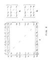
- Fig. 2 to Fig. 5 respectively explain aspects of embodiments of the present invention.
- correlations ⁇ r 1M , r 2M , whil, r M-1,M ⁇ between M th element data and 1 st , 2 nd , «, M-1 th elements data are calculated from complex digital received data from antenna elements of a uniform linear array, one correlation matrix ⁇ f is defined from the above correlations, and a noise subspace is calculated from the above correlation matrix by a liner operation. Thereafter, an arrival direction of each of the multipath waves is calculated based on a peak position of the spatial spectrum obtained from the above noise subspace or the zero-point of a polynomial obtained by an operation.
- correlations ⁇ r 21 , r 31 , ??, r M1 ⁇ between first element data and 2 nd , 3 rd , «, M th elements data are calculated from complex digital received data from antenna elements of the uniform linear array, and one correlation matrix ⁇ ⁇ f is defined from the above correlations. Thereafter, an arrival direction of each of the multipath waves is calculated based on a peak position of the spatial spectrum obtained from the above noise subspace or the zero-point of polynomial obtained by an operation.
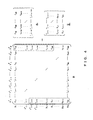
- correlations ⁇ r 12 , r 13 , ??, r 1M ⁇ between first element data and 2 nd , 3 rd , «, M th elements data are calculated from complex digital received data from antenna elements of the uniform linear array, and one correlation matrix ⁇ b is defined from the above correlations. Thereafter, an arrival direction of each of the multipath waves is calculated based on a peak position of the spatial spectrum obtained from the above noise subspace or the zero-point of a polynomial obtained by an operation.
- correlations ⁇ r M1 , r M2 , ??, r M,M-1 ⁇ between M th element data and 2 nd , 3 rd ,...., M th elements data are calculated from complex digital received data from antenna elements of a uniform linear array, one correlation matrix ⁇ ⁇ f is defined from the above correlations, and a noise subspace is calculated from the above correlation matrix by a linear operation. Thereafter, an arrival direction of each of the multipath waves is calculated based on a peak position of the spatial spectrum obtained from the above noise subspace or the zero-point of a polynomial obtained by an operation.
- correlations between first element data and 2 nd , 3 rd , «, M th elements data, and correlations between M th element data and 1 st , 2 nd , whil, M-1 th elements data are calculated from complex digital received data from antenna elements of a uniform linear array, one correlation matrix ⁇ (e.g.
- ⁇ [ ⁇ f , ⁇ ⁇ f , ⁇ b , ⁇ ⁇ b ] is defined from the obtained correlation matrixes ⁇ f , ⁇ ⁇ f , ⁇ b , ⁇ ⁇ b , and a noise subspace is calculated from the above correlation matrix by a liner operation. Thereafter, an arrival direction of each of the multipath waves is calculated based on a peak position of the spatial spectrum obtained from the above noise subspace or the zero-point of a polynomial obtained by an operation.
- correlations between first element data and 2 nd , 3 rd , whil, M th elements data, and correlations between M th element data and 1 st , 2 nd , whil, M-1 th elements data are calculated from complex digital received data from antenna elements of a uniform linear array, one correlation matrix ⁇ (e.g.
- ⁇ [ ⁇ f , ⁇ ⁇ f , ⁇ b ] is defined from three arbitrary matrixes in the obtained correlation matrixes ⁇ f , ⁇ ⁇ f , ⁇ b , ⁇ ⁇ b , and a noise subspace is calculated from the above correlation matrix by a linear operation. Thereafter, an arrival direction of each of the multipath waves is calculated based on a peak position of the spatial spectrum obtained from the above noise subspace or the zero-point of a polynomial obtained by an operation.
- correlations between first element data and 2 nd , 3 rd , «, M th elements data, and correlations between M th element data and 1 st , 2 nd , «, M-1 th elements data are calculated from complex digital received data from antenna elements of a uniform linear array
- a noise subspace is calculated from the above correlation matrix by a linear operation.
- the arrival direction of each of the multipath waves is calculated based on a peak position of the spatial spectrum obtained from the above noise subspace or the zero-point of a polynomial obtained by an operation.
- an arrival direction of each of uncorrelated signals in a white noise environment without time and spatial correlation is calculated.
- an arrival direction of each of the partially correlated signals in a white noise environment without time and spatial correlation is calculated.
- correlations between first element data and q + 2 th , q + 3 th , ising, M th elements data, and correlations between M th element data and 1 st , 2 nd , whil, M - 1 - q th elements data are calculated from complex digital received data from antenna elements of a uniform linear array, one correlation matrix ⁇ (e.g.
- correlations between first element data and q + 2 th , q + 3 th , ising, M th elements data, and correlations between M th element data and 1 st , 2 nd , whil, M - 1 - q th elements data are calculated from complex digital received data from antenna elements of a uniform linear array, one correlation matrix ⁇ (e.g.
- ⁇ [ ⁇ f , ⁇ ⁇ f ] ) is defined from two arbitrary matrixes in the correlation matrixes ⁇ f , ⁇ ⁇ f , ⁇ b , ⁇ ⁇ b obtained from the correlations, and a noise subspace is calculated from the above correlation matrix by a linear operation. Thereafter, an arrival direction of each of uncorrelated or partially correlatedmultipath signals in a spatially correlated noise environment is calculated based on a peak position of the spatial spectrum obtained from the above noise subspace or the zero-point of a polynomial obtained by an operation.
- correlations between first element data and q + 2 th , q + 3 th , ising, M th elements data, and correlations between M th element data and 1 st , 2 nd , whil, M - 1 - q th elements data are calculated from complex digital received data from antenna elements of a uniform linear array, one correlation matrix ⁇ (e.g.
- ⁇ [ ⁇ f , ⁇ ⁇ f , ⁇ b ] ) is defined from three arbitrary matrixes in the correlationmatrixes ⁇ f , ⁇ ⁇ f , ⁇ b , ⁇ ⁇ b obtained from the correlations, and a noise subspace is calculated from the above correlation matrix by a linear operation. Thereafter, an arrival direction of each of uncorrelated or partially correlated multipath signals in a spatially correlated noise environment is calculated based on a peak position of the spatial spectrum obtained from the above noise subspace or the zero-point of a polynomial obtained by an operation.
- correlations between first element data and q + 2 th , q + 3 th , ising, M th elements data, and correlations between M th element data and 1 st , 2 nd , whil, M - 1 - q th elements data are calculated from complex digital received data from antenna elements of a uniform linear array, one correlation matrix ⁇ (e.g.
- ⁇ [ ⁇ f , ⁇ ⁇ f , ⁇ b , ⁇ ⁇ b ] ) is defined from matrixes in the correlation matrixes ⁇ f , ⁇ ⁇ f , ⁇ b , ⁇ ⁇ b obtained from the correlations, and a noise subspace is calculated from the above correlation matrix by a linear operation. Thereafter, an arrival direction of each of uncorrelated or partially correlatedmultipath signals in a spatially correlated noise environment is calculated based on a peak position of the spatial spectrum obtained from the above noise subspace or the zero-point of a polynomial obtained by an operation.
- the technique for estimating an arrival direction of a signal in an aspect of embodiments of the present invention is applied to an arrival direction estimating device of a base station.
- the technique for estimating an arrival direction of a signal in an aspect of embodiments of the present invention is applied to a base station, and a device for shaping a transmitted beam which generates a beam whose peak is directed at an obtained arrival direction of a signal is provided in the base station.
- the present invention relates to a radio wave arrival direction estimating device for a base station which accurately estimates a radio wave arrival direction by using an array antenna with, a variable directivity receiving/transmitting device for a base station which varies the directivity of a beam of an antenna based on the estimation of the arrival direction by the radio wave arrival direction estimating device.
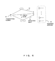
- Fig. 6 shows an arrangement of a transmitting source and a receiving antenna 20 in a base station.
- Fig. 7 is a block diagram for showing a multipath wave arrival direction estimating system realized by applying the embodiment of the present invention to the receiving antenna 20 in the base station.
- the multipath wave arrival direction estimating system including an arrival direction estimating unit 50 as shown in Fig. 7 is arranged.
- a signal which is directly incident on the receiving antenna 20 in the base station from the transmitting source 10 is a direct wave 11.
- signals which are incident on the receiving antenna 20 of the base station after being reflected by buildings and the like are reflected waves 12.
- Fig. 6 as an example, two reflected waves are shown, however, hereinafter, the total number of the direct wave and the reflected waves is p. Also, it is assumed that p is known.
- s k ( n ) ⁇ k s l ( n )
- ⁇ k is a multipath coefficient expressing a complex attenuation of the reflected wave s k (n) regarding the direct wave S 1 (n)
- ⁇ k ⁇ 0 and ⁇ 1 1.
- the arrival direction estimating system comprises an array antenna 30, a base band and digital processing unit 40, and the arrival direction estimating unit 50. Also, the array antenna 30 comprises M antenna elements 31 (where M>2p).
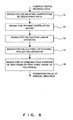
- Fig. 8 explains a process to be executed by the arrival direction estimating unit 50.
- the arrival direction estimating unit 50 comprises means for calculating correlation between array data 51, means for defining a correlation matrix 52, means for calculating a linear operator 53, means for calculating an orthogonal projection operator 54 and means for determining the peak position of spectrum or zero-point phase of a polynomial 55.
- the means for calculating a linear operator 53 divides the estimation value of the correlation matrix ⁇ into two parts as below, ⁇ ⁇ ⁇ [ ⁇ ⁇ 1 ⁇ ⁇ 2 ] ⁇ p ⁇ L - p - 1 where the px4p correlation matrix ⁇ 1 and the (L-p-1)x4p correlation matrix ⁇ 2 are respectively ⁇ 1 ⁇ [ ⁇ f 1 , ⁇ f 1 , ⁇ b 1 , ⁇ b 1 ] and ⁇ 2 ⁇ [ ⁇ f 2 , ⁇ f 2 , ⁇ b 2 , ⁇ b 2 ] .
- a linear operator P is obtained by a formula 14 below.
- P ⁇ ( ⁇ ⁇ 1 ⁇ ⁇ 1 H ) - 1 ⁇ ⁇ 1 ⁇ ⁇ 2 H
- ⁇ Q ⁇ Q ⁇ ( I L - p - 1 - P ⁇ H ( P ⁇ P ⁇ H + I p ) P ⁇ ) - 1 Q ⁇ H
- the means for determining peak positions of the spectrum or zero-point phase of a polynomial 55 calculates the arrival direction of each of the multipath waves from the highest peak position among the p peaks of the spectrum P( ⁇ ) in a formula 16 below, or from the zero-point which is the closest to a unit circle among the p zero-points of the polynomial p(z) as shown in a formula 17 below, so that the estimation result ⁇ ⁇ k ⁇ is output, P ( ⁇ ) ⁇ 1 a H ( ⁇ ) ⁇ Q ⁇ a ( ⁇ ) p ( z ) ⁇ z L - 2 p H ( z ) ⁇ Q ⁇ p ( z ) where a ⁇ ( ⁇ ) ⁇ [ l , e j ⁇ 0 r ( ⁇ ) , ⁇ ⁇ ⁇ , e j ⁇ 0 ( L - 2 ) r ( ⁇ ) ] T ,
- the arrival direction estimating unit 50 can estimate the arrival direction of each of the multipath waves.
- the number of antenna elements M is ten.
- Fig. 9 shows the RMSE (root mean-squared-error) of estimation values ⁇ 1 and ⁇ 2 of the arrival directions.
- the influence of observation noise is removed by suitably selecting the correlation r ⁇ ik of array data which constitutes the correlation matrix ⁇ f , ⁇ f , ⁇ b , ⁇ b so that the estimation performance of the present invention is much better than that of the spatial smoothing based MUSIC utilizing eigenvalue decomposition. Also, there is only a very slight difference between the theoretical error in the technique of the present invention and CRB. Further, the computation amount of the technique of the present invention is greatly reduced becoming 1/7.147 of the computation amount in the spatial smoothing based MUSIC.
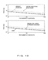
- the estimation performance of the arrival direction of each of the multipath waves based on the present invention with respect to the length of the received data is discussed.
- the SNR is 10dB
- the length of the received data N is varied within a range between 10 and 1000.
- Fig. 10 shows the RMSE of each of the estimation values ⁇ 1 and ⁇ 2 obtained by calculation after one thousand times.
- the estimation error expressed as RMSE according the technique for the present invention is very close to the ideal minimum error shown as CRB when the length of data is great.
- the technique according to the present invention provides an estimation of the arrival directions more accurately than the conventional spatial smoothing based MUSIC.
- the estimated correlated matrix ⁇ is constituted by ⁇ ⁇ ⁇ [ ⁇ ⁇ f , ⁇ ⁇ f , ⁇ ⁇ b , ⁇ ⁇ b ] has been explained.
- the estimated correlation matrix ⁇ is defined by a combination of the correlation matrices ⁇ f , ⁇ ⁇ f , ⁇ b , ⁇ ⁇ b , the method for estimating an arrival direction of each of the multipath waves, the partially correlated signals or the uncorrelated signals in the white noise environment without a correlation can be easily realized.
- the ( L - q - 1 ) ⁇ p correlation matrixes ⁇ f , ⁇ ⁇ f , ⁇ b , ⁇ ⁇ b can be defined from the estimation value r ⁇ ik of the correlation of array data as shown in and expressed by Fig. 4, Fig.
- the reason that the correlation matrix is defined by removing the element closest to the diagonal element of the covariance matrix R is that the noise components ride on a part which is close to the diagonal element of the covariance matrix R. Therefore, by defining the correlation matrix by removing the element which is closest to the diagonal element of the covariance matrix R, a technique in which the signal arrival directions are accurately estimated even when the noise component is included can be provided.
- a reception beam shaper for a base station which shapes a beam whose intensity peak is directed in a desired arrival direction can be realized.
- Fig. 11 explains the reception beam shaper for a base station which shapes a beam whose intensity peak is directed in a desired arrival direction realized by utilizing the arrival direction estimating device which employs the technique for estimating an arrival direction of each of the signals in an embodiment of the present invention.
- a signal is received by the array antenna 20
- the complex digital received data is obtained from the base band and digital processing unit 30, and a desired beam can be shaped by a beam shaper 60 which uses an estimation value of an arrival direction obtained from the arrival direction estimating unit 40.
- the data obtained by extracting a desired signal by suppressing interference and noise is sent from the beam shaper 60 to a channel receiving unit 70, and in the channel receiving unit 70, a receiving process according to the common and conventional method is executed so that the received data is obtained.
- the beam shaper 70 various configurations are possible by utilizing the information regarding the arrival direction obtained by the technique according to the present invention.
- a beam can be shaped to a desired arrival direction of a signal.
- the technique can be utilized for controlling the peak of a reception beam in which the peak of the receiving sensitivity at a base station is directed to the estimated arrival direction, and also can be utilized for controlling the peak of a transmitted beam so that the intensity peak of the transmitted signal is directed to the estimated arrival direction when the base station transmits a signal.
- the present invention realizes estimation of an arrival direction of each of the signals incident at angles which are spatially close to one another, with a reduced computation amount, without utilizing the eigenvalue decomposition.
- the technique according to the present invention realizes an accurate estimation of the arrival direction of a signal incident on an array antenna at a base station even when the length of received data is not sufficient or when the signal-to-noise ratio (SNR) is low.
- the technique according to the present invention realizes a much better estimation performance with a reduced computation amount than the conventional spatial smoothing based MUSIC. Accordingly, the accuracy of the estimation of the arrival direction of each of the multipath waves can be enhanced.
- variable directivity receiving/transmitting device for a base station which can shape a beam having a directivity in a desired direction can be realized.
Landscapes
- Physics & Mathematics (AREA)
- Engineering & Computer Science (AREA)
- General Physics & Mathematics (AREA)
- Radar, Positioning & Navigation (AREA)
- Remote Sensing (AREA)
- Radio Transmission System (AREA)
- Radar Systems Or Details Thereof (AREA)
- Variable-Direction Aerials And Aerial Arrays (AREA)
Abstract
An incoming radio wave is received by array antenna elements which constitute an array antenna, and the correlation between received data of some array antenna elements is calculated to define a correlation matrix which does not undergo additional noise present in each array antenna element. Next, a noise subspace is defined from the correlation matrix defined by a simple linear operation on the basis of division of an array response matrix to estimate a signal that is incident on the array antenna. Since it is unnecessary to calculate the correlation between the data received by all the array antenna elements, and to perform eigenvalue decomposition, the computation amount is reduced and the noise resistance is improved.
Description
- The present invention relates to a radio wave arrival direction estimating device for a base station which estimates a radio waves arrival direction with high accuracy by using an array antenna, and to a variable directivity receiving/transmitting device for a base station which varies the directivity of beam of an antenna based on the estimation of the arrival direction by the radio wave arrival direction estimating device. The present invention is of a technique by which an arrival direction of each of a plurality of incident signals (signals which are not uncorrelated to one another, or the multipath waves which are perfectly correlated) are estimated by means which is effective in calculation, and is especially a technique for estimating the arrival direction of each of the incident waves with similar incident directions with a high accuracy even when the length of received data is not sufficient and when the SNR is low.
- In recent years, the study and development of adaptive array antenna for mobile communications has gathered interest. In the adaptive array antenna, a plurality of antenna elements is arrayed in a shape and in different spatial positions. A technique for estimating an arrival direction of each of the radio waves incident at an antenna (referred to also as a signal, from the view point of signal processing) is thought to be an important elemental technique for an adaptive array antenna. As for a technique for estimating the arrival direction of each of the signals, a subspace-based method which utilizes the orthogonality between a signal subspace and a noise subspace is well known from the view point of the estimation accuracy and the computation amount. A conventional subspace-based method requires processes such as Eigenvalue decomposition (EVD) of an array covariance matrix, singular value decomposition (SVD) of an array data matrix or the like in order to obtain a signal subspace (or a noise subspace). However, for a real installed array antenna, especially in the case where there are many array elements, the calculation process for the eigenvalue decomposition (or the singular value decomposition) becomes complex so that much time is required for the calculation.
- Conventionally, as a method for estimating an arrival direction of each of the uncorrelated incident waves by using an array antenna, the subspace-base method utilizing the orthogonality between a signal subspace and a noise subspace is well known from the view point of the complexity of calculation, the accuracy of estimation and the like. As a representative example thereof, there is MUSIC (Multiple signal classification) (for details of this technique, refer to "Multiple emitter location and signal parameter estimation," by R.O.Schmidt, IEEE Trans. Antennas and Propagation, vol. 34, no. 3, pp. 276-280 (1986)). Also, as a measure for a technique for estimating an arrival direction of each of perfectly correlated multipath waves, the subspace-based method with spatial smoothing is well known. As a representative example thereof, there is spatial smoothing based MUSIC (for the details of this technique, refer to "On spatial smoothing for direction-of-arrival estimation of coherent signals," by T.J. Shan, M. Wax and T. Kailath, IEEE Trans. Acoust., Speech, Signal Processing, vol. 33, no. 4, pp. 806-811(1985), and also "Forward/backward spatial smoothing techniques for coherent signals identification, by S.U. Pillai andB.H. Kwon, IEEE Trans. Acoust., Speech, Signal Processing, vol. 37, no. 1, pp. 8-15 (1989)).
- In the subspace-based method for estimating an arrival direction of each of uncorrelated signals, an array covariance matrix from signals incident on an array antenna is obtained so that a signal subspace and a noise subspace are obtained by the eigenvalue decomposition of the array covariance matrix. Then, the arrival direction of each of the signals is estimated by utilizing the orthogonality between the signal subspace and the noise subspace. However, for the estimation of an arrival direction of each of the correlated signals (including the perfectly correlated multipath waves), a uniform linear array (ULA) is divided into subarrays in order to suppress the correlation of incident signals and the dimension of the signal subspace of the spatially averaged covariance matrix is recovered into the number of the multipath waves by conducting an averaging operation on the covariance matrix of each subarray. Accordingly, the estimation of the arrival direction of each of the correlated signals is realized by utilizing the orthogonality between the signal subspace and the noise subspace similarly to the conventional subspace-based method.
- In order to explain a demerit of the subspace-based method for a conventional method for estimation of a signal arrival direction, spatial smoothing based MUSIC for estimating an arrival directions of each of the multipath waves will be briefly explained as is discussed in an exemplary document "On spatial smoothing for direction-of-arrival estimation of coherent signals," by T. J. Shan, M. Wax and T. Kailath, IEEE Trans. Acoust., Speech, Signal Processing, vol. 33, no. 4, pp. 806-811 (1985).
- Here, it is assumed that p multipath wave narrow band signals {s k (n)} are incident on a uniform linear array including M array elements, at an angle of {θk} (where k=1 to p). The array received signal for each element can be express as below,

where A = [a(θ 1),a(θ 2),···,a(θ p )], a(θ k )=[1,e jω0 r(θ r ),···,e jω0(M-1)τ(θ t )] r , s(n)=[s 1( n ),s 2( n ),···,s p (n)] r , w(n)=[w 1(n),w 2( n ),···,w M (n)] T , ω0=2πf0, τ(θ)k) = (d/c) sinθk. And f0 is a frequency of a carrier wave, c is a propagation speed, and d is element spacing (a half-wavelength). Also, (•)T means a transpose, a(θk) and A are respectively a response vector and a response matrix of an array. Also, wi(n) is white Gaussian noise which is independent among elements and has the average value of zero and whose electric power is σ2. Here, the array covariance matrix is expressed as below,
where E{•} and (•)H respectively express an expectation value operation and a complex conjugate transpose, Rs=E{s (n) sH(n)} is the covariance matrix of an incident multipath wave, IM is an M×M unit matrix. Further, when the correlation rik of the observation data yi(n) and yk(n) is defined by rik=E{yI(n) yk*(n)}, the above array covariance matrix R can be clearly expressed by a formula below,
- Fig. 1 explains the dividing of the uniform linear array into subarrays.
- In the spatial smoothing based MUSIC, in order to estimate the arrival directions {θk} of perfectly correlated multipath waves, the entire uniform linear array is divided into L overlapped subarrays including m elements (where 1≤m≤M) as shown in Fig. 1. In the above operation, m and L are respectively called the size of the subarray and the number of the subarrays, and L=M-m+1 is satisfied. Based on the
formula 1, a reception vector x1(n) of a first subarray can be expressed by formula 4 as below,
where A m=[a m(θ1), a m(θ2), ...... a m(θp)] a m (θ k )=[1,e jω0 r(θ k ),···,e jω n (m-1)r(θ i )] r , w 1(n)=[w1(n), w1+1(n),......, w1-m+1(n)]T, D is a diagonal matrix with the elements e jω n r(θ1),e jω0τ(θ 2) , ......, e jω0(m-1)r(θ p ), and l=1, 2, ......, L. Also, a m(θk) and A m are respectively a response vector and a response matrix of a subarray. Accordingly, the covariance matrix of the first subarray can be expressed byformula 5 as below.


where ei and λi are respectively an eigenvector and an eigenvalue of the matrix
- By the eigenvalue analysis of the covariance matrix


where i=p+1, ......, m. Based on the above orthogonality, the spectrum

where a m (θ)=[1,e jω0τ(θ),···,e jω0(m-1)r(θ)] r . In the spatial smoothing based MUSIC, the arrival direction of each of the incident multipath waves is estimated based on the position of the p maxima of the spectrum given by the formula 7. - As obvious from the formula 7, the subspace-based method for estimating the arrival direction, such as the (spatial smoothing based) MUSIC requires the eigenvalue decomposition of the array covariance matrix in order to obtain the signal subspace or the noise subspace. However, for a real installed array antenna, especially in the case where there are many array elements, or for the estimation of varying arrival directions, by real time processing, the calculation process for the eigenvalue decomposition (or the singular value decomposition) becomes complex so that much time is required for the calculation. Accordingly, the performance of the conventional subspace-based method for estimating the arrival direction based on the eigenvalue decomposition in the actual application is restricted by the processing time for the eigenvalue decomposition process because of the load of the calculation. Further, if the estimation of the arrival direction of each of the signals incident on the array is not realized quickly and accurately, the received/transmitted beam of the base station cannot be shaped accurately, and also, the performance of the receiving and transmitting system of the base station is impaired.
- It is an object of the present invention to provide a technique in which an arrival direction of each of the signals incident at angles which are spatially close to one other (signals which are not uncorrelated to one another, or the multipath waves which are perfectly correlated) is accurately estimated with a reduced computation amount without utilizing the eigenvalue decomposition, even when the length of data received by the array antenna is not sufficient or when the signal-to-noise ratio is low.
- A method for estimating signal arrival direction according to the present invention comprises a step of obtaining correlations among the data of some of the elements based on received signals from a plurality of array antenna elements which are linearly arrayed in different spatial positions with uniform element spacing, and defining one correlation matrix from the correlations, a step of estimating a noise subspace from the correlation matrix by a linear operation, and an estimation step of calculating a peak position of the spatial spectrum obtained from the noise subspace or a zero-point of a polynomial which is equivalent to the peak position, and calculating a signal arrival direction.
- According to the present invention, the correlation matrix utilizes only the correlation among some antenna elements, so that the large amount of data as in the case of handling the correlation among all of the antenna elements does not have to be handled. Further, the eigenvalue decomposition is not performed so that the computational amount is reduced. Therefore the present invention can provide a feasible method for applying the estimation of the arrival direction of each signal varying in real time to a base station.
-
- Fig. 1 explains dividing of a uniform linear array into subarrays;
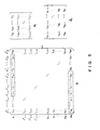
- Fig. 2 to Fig. 5 respectively explain aspects of embodiments of the present invention;
- Fig. 6 shows an arrangement of a transmitting source and a receiving
antenna 20 in a base station; - Fig. 7 is a block diagram for showing a multipath wave arrival direction estimating system realized by applying embodiments of the present invention to the receiving
antenna 20 in the base station; - Fig. 8 explains a process to be executed by an arrival
direction estimating unit 50; - Fig. 9 shows RMSE (root mean-squared-errors) of estimation values θ̂ 1 and θ̂ 2 of the arrival directions;
- Fig. 10 shows RMSE of each of the estimation values θ̂ 1 and θ̂ 2 obtained by one thousand times calculation; and
- Fig. 11 explains a reception beam shaper for a base station which shapes a beam whose peak is directed to a desired arrival direction, realized by utilizing the arrival direction estimating device which employs a technique for estimating the arrival direction of each signal, in an embodiment of the present invention.
- The present invention provides a technique in which an arrival direction of each of the signals incident at angles which are spatially close to one other is accurately estimated with a reduced computation amount without utilizing eigenvalue decomposition, even when the amount of data received by the array antenna is not sufficient or when the signal-to-noise ratio (SNR) is low, in a white noise environment without time and spatial correlation or in a noise environment with spatial correlation.
- Fig. 2 to Fig. 5 respectively explain aspects of embodiments of the present invention.
- In order to realize the above object, in an aspect of embodiments of the present invention, as shown in Fig. 2, correlations {r1M, r2M, ......, rM-1,M} between Mth element data and 1st, 2nd,......, M-1th elements data are calculated from complex digital received data from antenna elements of a uniform linear array, one correlation matrix Φf is defined from the above correlations, and a noise subspace is calculated from the above correlation matrix by a liner operation. Thereafter, an arrival direction of each of the multipath waves is calculated based on a peak position of the spatial spectrum obtained from the above noise subspace or the zero-point of a polynomial obtained by an operation.
- Also, in another aspect of the embodiments of the present invention, as shown in Fig. 2, correlations {r21, r31, ......, rM1} between first element data and 2nd, 3rd,......, Mth elements data are calculated from complex digital received data from antenna elements of the uniform linear array, and one correlation matrix

- Also, in yet another aspect of the embodiments of the present invention, as shown in Fig. 3, correlations {r12, r13, ......, r1M} between first element data and 2nd, 3rd,......, Mth elements data are calculated from complex digital received data from antenna elements of the uniform linear array, and one correlation matrix Φb is defined from the above correlations. Thereafter, an arrival direction of each of the multipath waves is calculated based on a peak position of the spatial spectrum obtained from the above noise subspace or the zero-point of a polynomial obtained by an operation.
- Also, in still another aspect of the embodiments of the present invention, as shown in Fig. 3, correlations {rM1, rM2, ......, rM,M-1} between Mth element data and 2nd, 3rd,...., Mth elements data are calculated from complex digital received data from antenna elements of a uniform linear array, one correlation matrix
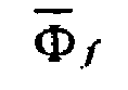
- Also, in still another aspect of the embodiments of the present invention, as shown in Fig. 2 and Fig. 3, correlations between first element data and 2nd, 3rd, ......, Mth elements data, and correlations between Mth element data and 1st, 2nd, ......, M-1th elements data are calculated from complex digital received data from antenna elements of a uniform linear array, one correlation matrix Φ (e.g.


- Also, in still another aspect of the embodiments of the present invention, as shown in Fig. 2 and Fig. 3, correlations between first element data and 2nd, 3rd,......, Mth elements data, and correlations between Mth element data and 1st, 2nd, ......, M-1th elements data are calculated from complex digital received data from antenna elements of a uniform linear array, one correlation matrix Φ (e.g.

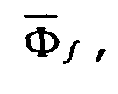

- Also, in still another aspect of the embodiments of the present invention, as shown in Fig. 2 and Fig. 3, correlations between first element data and 2nd, 3rd, ......, Mth elements data, and correlations between Mth element data and 1st, 2nd, ......, M-1th elements data are calculated from complex digital received data from antenna elements of a uniform linear array, one correlation matrix Φ (e.g.


- Further, by using a technique for estimating an arrival direction of signal in an aspect of the embodiments of the present invention, an arrival direction of each of uncorrelated signals in a white noise environment without time and spatial correlation is calculated.
- Further, by using a technique for estimating an arrival direction of a signal in an aspect of the embodiments of the present invention, an arrival direction of each of the partially correlated signals in a white noise environment without time and spatial correlation is calculated.
- Also, in still another aspect of the embodiments of the present invention, as shown in Fig. 4 and Fig. 5, correlations between first element data and

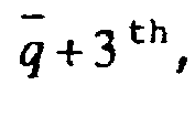


- Also, in still another aspect of the embodiments of the present invention, as shown in Fig. 4 and Fig. 5, correlations between first element data and


- Also, in still another aspect of the embodiments of the present invention, as shown in Fig. 4 and Fig. 5, correlations between first element data and


- Also, in still another aspect of the embodiments of the present invention, as shown in Fig. 4 and Fig. 5, correlations between first element data and

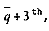


- Also, the technique for estimating an arrival direction of a signal in an aspect of embodiments of the present invention is applied to an arrival direction estimating device of a base station.
- Also, the technique for estimating an arrival direction of a signal in an aspect of embodiments of the present invention is applied to a base station, and a device for shaping a transmitted beam which generates a beam whose peak is directed at an obtained arrival direction of a signal is provided in the base station.
- The present invention relates to a radio wave arrival direction estimating device for a base station which accurately estimates a radio wave arrival direction by using an array antenna with, a variable directivity receiving/transmitting device for a base station which varies the directivity of a beam of an antenna based on the estimation of the arrival direction by the radio wave arrival direction estimating device.
- Hereinafter, by referring to the drawings, the wave arrival direction estimating device for a base station will be explained as embodiments of the present invention. In the drawings, substantially like members or members having like functions are denoted by like numerals/characters. Also, for simplicity, the explanation is given for one of the plurality of the previously described embodiments.
- Fig. 6 shows an arrangement of a transmitting source and a receiving
antenna 20 in a base station. Fig. 7 is a block diagram for showing a multipath wave arrival direction estimating system realized by applying the embodiment of the present invention to the receivingantenna 20 in the base station. - At the receiving
antenna 20 of the base station, the multipath wave arrival direction estimating system including an arrivaldirection estimating unit 50 as shown in Fig. 7 is arranged. Here, a signal which is directly incident on the receivingantenna 20 in the base station from the transmittingsource 10 is adirect wave 11. Also, signals which are incident on the receivingantenna 20 of the base station after being reflected by buildings and the like are reflectedwaves 12. In Fig. 6, as an example, two reflected waves are shown, however, hereinafter, the total number of the direct wave and the reflected waves is p. Also, it is assumed that p is known. Further, the relationship between the direct wave and the reflected wave is expressed by the formula below,
- The arrival direction estimating system comprises an
array antenna 30, a base band anddigital processing unit 40, and the arrivaldirection estimating unit 50. Also, thearray antenna 30 comprises M antenna elements 31 (where M>2p). - Fig. 8 explains a process to be executed by the arrival
direction estimating unit 50. - The arrival
direction estimating unit 50 comprises means for calculating correlation betweenarray data 51, means for defining acorrelation matrix 52, means for calculating alinear operator 53, means for calculating anorthogonal projection operator 54 and means for determining the peak position of spectrum or zero-point phase of a polynomial 55. - Hereinafter, the technique for estimating the multipath wave arrival direction in the arrival
direction estimating unit 50 will be explained by referring to Fig. 8. Initially, the means for calculating correlation betweenarray data 51 prepares a reception vector y(n) as expressed by theformula 1, with the complex digital signals y1(n), y2(n), ......, yM(n) obtained from the base band anddigital processing unit 40. Further, a vector ϕ̂ of the correlation between the signal y(n) and y*M(n), and a vector
formula 11 by using the reception vector

- Next, the means for defining
correlation matrix 52 defines the estimated (L-1)×p correlation matrices φ̂ f ,

formulae 11,
where L=M-p+ 1. It is known from theformula 2 that the correlation matrixes φ̂ f ,

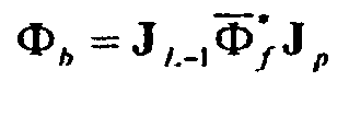


- Next, the means for calculating a
linear operator 53 divides the estimation value of the correlation matrix Φ̂ into two parts as below,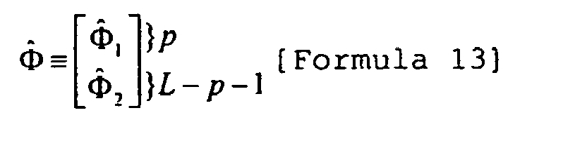
where the px4p correlation matrix Φ1 and the (L-p-1)x4p correlation matrix Φ2 are respectively


- Next, the means for calculating
orthogonal projection operator 54 obtains an orthogonal projection operator
formula 15 below.
- Finally, the means for determining peak positions of the spectrum or zero-point phase of a polynomial 55 calculates the arrival direction of each of the multipath waves from the highest peak position among the p peaks of the spectrum P(θ) in a formula 16 below, or from the zero-point which is the closest to a unit circle among the p zero-points of the polynomial p(z) as shown in a formula 17 below, so that the estimation result {θ̂ k } is output,


where
e jω0 r(θ). - As above, the arrival
direction estimating unit 50 can estimate the arrival direction of each of the multipath waves. Hereinafter, a more detailed explanation will be given for a specific example of a calculated simulation. Here, it is assumed that the number of antenna elements M is ten. Also, two multipath waves having the same power (p=2) are incident on the array antenna respectively with angles θ1=5° and θ2=12°. - Initially, estimation performance of an arrival direction of each of the multipath waves based on an embodiment of the present invention with respect to the signal-to-noiseratio (SNR) is discussed. Now, assuming that the length of the received data N is 128, the SNR is varied within a range between -10dB and 25dB. Calculation is conducted one thousand times for each value of SNR.
- Fig. 9 shows the RMSE (root mean-squared-error) of estimation values θ̂ 1 and θ̂ 2 of the arrival directions.
- For comparison, results using a theoretical error of the estimation of an arrival direction of each of the multipath waves based on the present invention, CRB (Cramér-Rao lower bound) indicating an ideal minimum error of the arrival direction estimation and the conventional spatial smoothing based MUSIC (m=7) are plotted.
- As is obvious from Fig. 9, in the technique for estimating an arrival direction of a signal based on the present invention, the influence of observation noise is removed by suitably selecting the correlation r̂ ik of array data which constitutes the correlation matrix Φ f ,


- Next, the estimation performance of the arrival direction of each of the multipath waves based on the present invention with respect to the length of the received data is discussed. Now, assuming that the SNR is 10dB, the length of the received data N (the number of snapshots) is varied within a range between 10 and 1000.
- Fig. 10 shows the RMSE of each of the estimation values θ̂ 1 and θ̂ 2 obtained by calculation after one thousand times.
- As shown in Fig. 10, the estimation error expressed as RMSE according the technique for the present invention is very close to the ideal minimum error shown as CRB when the length of data is great. However, even when the amount of the received data is not great, the technique according to the present invention provides an estimation of the arrival directions more accurately than the conventional spatial smoothing based MUSIC.
- In the above example, an aspect of the method for estimating the arrival direction of each of the multipath waves in which the estimated correlated matrix Φ̂ is constituted by


- Further, when it is assumed that the length of the spatial correlation of noise is


formula 12. Here, it is assumed that


- Further, by utilizing the signal arrival direction estimating device which employs the technique for estimating an arrival direction of each of the signals as explained above, a reception beam shaper for a base station which shapes a beam whose intensity peak is directed in a desired arrival direction can be realized.
- Fig. 11 explains the reception beam shaper for a base station which shapes a beam whose intensity peak is directed in a desired arrival direction realized by utilizing the arrival direction estimating device which employs the technique for estimating an arrival direction of each of the signals in an embodiment of the present invention.
- Here, in a configuration of the reception beam shaper in the
base station 20, a signal is received by thearray antenna 20, the complex digital received data is obtained from the base band anddigital processing unit 30, and a desired beam can be shaped by abeam shaper 60 which uses an estimation value of an arrival direction obtained from the arrivaldirection estimating unit 40. The data obtained by extracting a desired signal by suppressing interference and noise is sent from thebeam shaper 60 to achannel receiving unit 70, and in thechannel receiving unit 70, a receiving process according to the common and conventional method is executed so that the received data is obtained. Also, as thebeam shaper 70, various configurations are possible by utilizing the information regarding the arrival direction obtained by the technique according to the present invention. For example, by utilizing a beam shaping technique discussed in "An algorithm for linearly constrained adaptive array processing," by O.L. Frost, Proc. IEEE, vol. 60, no. 8, pp. 926-935 (1975) and "Array beam forming based on cyclic signal detection", by J. Xin, HTsuji, YHase, andA. Sano, Proc. IEEE 48th Vehicular Technology Conference, pp. 890-894, Ottawa, Canada (1998) and the like, a beam can be shaped to a desired arrival direction of a signal. - The technique can be utilized for controlling the peak of a reception beam in which the peak of the receiving sensitivity at a base station is directed to the estimated arrival direction, and also can be utilized for controlling the peak of a transmitted beam so that the intensity peak of the transmitted signal is directed to the estimated arrival direction when the base station transmits a signal.
- As explained above, the present invention realizes estimation of an arrival direction of each of the signals incident at angles which are spatially close to one another, with a reduced computation amount, without utilizing the eigenvalue decomposition. As clearly demonstrated in the specific example of the calculated simulation, the technique according to the present invention realizes an accurate estimation of the arrival direction of a signal incident on an array antenna at a base station even when the length of received data is not sufficient or when the signal-to-noise ratio (SNR) is low. Also, the technique according to the present invention realizes a much better estimation performance with a reduced computation amount than the conventional spatial smoothing based MUSIC. Accordingly, the accuracy of the estimation of the arrival direction of each of the multipath waves can be enhanced. Further, by utilizing information regarding the signal arrival direction obtained by the method for estimating the arrival direction of a signal according to the present invention, a variable directivity receiving/transmitting device for a base station which can shape a beam having a directivity in a desired direction can be realized.
Claims (19)
- A method for estimating signal arrival direction, comprising:obtaining correlations among some of elements based on received signals from a plurality of array antenna elements which are linearly arrayed in different spatial positions with uniform element spacings, and defining one correlation matrix from the correlations;estimating a noise subspace from the correlation matrix by a linear operation; andcalculatingapeakpositionof the spatial spectrum obtained from the noise subspace or a zero-point of a polynomial which is equivalent to the peak position, and calculating a signal arrival direction.
- The method for estimating signal arrival direction according to claim 1, wherein:the correlation matrix is obtained from correlations between Mth element data and 1st, 2nd,......, M-1th elements data when it is assumed that M is the number of the antenna elements.
- The method for estimating signal arrival direction according to claim 1, wherein:the correlation matrix is obtained from correlations between first element data and 2nd, 3rd,......, Mth elements data when it is assumed that M is the number of the antenna elements.
- The method for estimating signal arrival direction according to claim 1, wherein:the correlation matrix is obtained by a formula

- The method for estimating signal arrival direction according to claim 1, wherein:the correlation matrix is obtained by a formula

- The method for estimating signal arrival direction according to claim 1, wherein:the correlation matrix is obtained by a formula

- The method for estimating signal arrival direction according to claim 1, wherein:the correlation matrix is obtained by a formula

- The method for estimating signal arrival direction according to claim 1, wherein:the correlation matrix is defined from two arbitrary matrixes obtained by formulae


- The method for estimating signal arrival direction according to claim 1, wherein:the correlation matrix is defined from three arbitrary matrixes obtained by formulae


- The method for estimating signal arrival direction according to claim 1, wherein:the correlation matrix is defined by a combination of four matrixes obtained by formulae


- The method for estimating signal arrival direction according to claim 1, wherein:the correlation matrix is obtained from correlations between Mth element data and 1st, 2nd, ......,


- The method for estimating signal arrival direction according to claim 1, wherein:the correlation matrix is obtained from correlations between first element data and


- The method for estimating signal arrival direction according to claim 1, wherein:the correlation matrix is defined by using one arbitrary, two arbitrary, three arbitrary or all four matrixes obtained by formulae


- The method for estimating signal arrival direction according to one of claim 1 to claim 13, wherein:the method for estimating signal arrival direction is realized in a base station.
- The method for estimating signal arrival direction according to one of claim 1 to claim 13, wherein:the method for estimating signal arrival direction is realized in a base station, and the base station directs a peak of a received beam which is a peak of sensitivity when an antenna receives the received signal to an estimated arrival direction.
- The method for estimating signal arrival direction according to one of claim 1 to claim 13, wherein:the method for estimating signal arrival direction is realized in abase station, and the base station directs, to an estimated arrival direction, a peak of a transmitted beam which is a transmission peak when an antenna transmits a signal.
- A program for causing an information processing device to execute a method for estimating signal arrival direction, comprising:obtaining correlations among some of elements data based on received signals from a plurality of array antenna elements which are linearly arrayed in different spatial positions with uniform element spacings, and defining one correlation matrix from the correlations;estimating a noise partial space from the correlation matrix by a linear operation; andcalculating a spatial spectrum obtained from the noise partial space or a zero-point of a polynomial, and calculating a signal arrival direction.
- A storage medium whose content can be read by an information processing device, storing a program which causes an information processing device to execute a method for estimating a signal arrival direction, comprising:obtaining correlations among some elements data based on received signals from a plurality of array antenna elements which are linearly arrayed in different spatial positions with uniform element spacings, and defining one correlation matrix from the correlations;estimating a noise partial space from the correlation matrix by a linear operation; andcalculating a spatial spectrum obtained from the noise partial space or a zero-point of a polynomial, and calculating a signal arrival direction.
- A signal arrival direction estimating device, comprising:correlation matrix defining means for obtaining correlations among some elements data based on received signals from a plurality of array antenna elements which are linearly arrayed in different spatial positions with uniform element spacings, and defining one correlation matrix from the correlations;noise partial space estimating means for estimating a noise partial space from the correlation matrix by a linear operation; andarrival direction estimating means for calculating a spatial spectrum obtained from the noise partial space or a zero-point of a polynomial, and calculating a signal arrival direction.
Applications Claiming Priority (1)
| Application Number | Priority Date | Filing Date | Title |
|---|---|---|---|
| PCT/JP2003/006411 WO2004104620A1 (en) | 2003-05-22 | 2003-05-22 | Technique for estimating signal arrival direction not by utilizing eigenvalue decomposition and reception beam shaper |
Publications (2)
| Publication Number | Publication Date |
|---|---|
| EP1626287A1 true EP1626287A1 (en) | 2006-02-15 |
| EP1626287A4 EP1626287A4 (en) | 2009-08-05 |
Family
ID=33463147
Family Applications (1)
| Application Number | Title | Priority Date | Filing Date |
|---|---|---|---|
| EP03730586A Withdrawn EP1626287A4 (en) | 2003-05-22 | 2003-05-22 | TECHNIQUE FOR ESTIMATING THE ARRIVAL DIRECTION OF A SIGNAL, WITHOUT USING THE DECOMPOSITION OF THE CLEAN VALUE, AND MEANS FOR FORMING THE RECEPTION BEAMS |
Country Status (4)
| Country | Link |
|---|---|
| US (1) | US7068221B2 (en) |
| EP (1) | EP1626287A4 (en) |
| JP (1) | JP4339801B2 (en) |
| WO (1) | WO2004104620A1 (en) |
Cited By (5)
| Publication number | Priority date | Publication date | Assignee | Title |
|---|---|---|---|---|
| CN102812735A (en) * | 2010-02-05 | 2012-12-05 | 诺基亚西门子通信公司 | Method for scheduling user equipment in a radio communications system and apparatus thereof |
| CN103760518A (en) * | 2013-10-29 | 2014-04-30 | 电子科技大学 | Measuring method for antenna array direction vectors of a plurality of signals with unknown directions |
| CN103926555A (en) * | 2013-11-26 | 2014-07-16 | 同方电子科技有限公司 | Method for testing amplitude and phase response of antenna array receiver through non-circular signals |
| CN106501765A (en) * | 2016-12-02 | 2017-03-15 | 南京邮电大学 | A kind of Maximum Likelihood DOA Estimation based on quadratic sum and Semidefinite Programming |
| CN111965593A (en) * | 2020-07-10 | 2020-11-20 | 北京邮电大学 | Method and device for determining direction of arrival of a signal |
Families Citing this family (33)
| Publication number | Priority date | Publication date | Assignee | Title |
|---|---|---|---|---|
| WO2006016408A1 (en) * | 2004-08-12 | 2006-02-16 | Fujitsu Limited | Radio wave arrival direction adaptive deduction tracking method and device |
| WO2006067857A1 (en) * | 2004-12-24 | 2006-06-29 | Fujitsu Limited | Arrival direction estimating device and program |
| DE102005008734B4 (en) * | 2005-01-14 | 2010-04-01 | Rohde & Schwarz Gmbh & Co. Kg | Method and system for detecting and / or eliminating sinusoidal noise in a noise signal |
| JP4805591B2 (en) * | 2005-03-17 | 2011-11-02 | 富士通株式会社 | Radio wave arrival direction tracking method and radio wave arrival direction tracking device |
| JP4722132B2 (en) * | 2005-07-11 | 2011-07-13 | 富士通株式会社 | Arrival wave number estimation method, arrival wave number estimation apparatus, and radio apparatus |
| US7508875B1 (en) * | 2005-09-15 | 2009-03-24 | Bae Systems Information And Electronic Systems Integration Inc. | Correlation matrix estimation via adaptive array perturbational processing to enable jammer location |
| WO2007101451A1 (en) * | 2006-03-09 | 2007-09-13 | Fundacio Privada Centre Tecnologic De Telecomunicacions De Catalunya | Method and system for estimating directions-of-arrival in low power or low sample size scenarios |
| US7945061B1 (en) * | 2006-06-07 | 2011-05-17 | Bae Systems Information And Electronic Systems Integration Inc. | Scalable architecture for subspace signal tracking |
| JP5320792B2 (en) | 2008-03-28 | 2013-10-23 | 富士通株式会社 | Arrival direction estimation apparatus, arrival direction estimation method, and arrival direction estimation program |
| US8571255B2 (en) * | 2009-01-07 | 2013-10-29 | Dolby Laboratories Licensing Corporation | Scalable media fingerprint extraction |
| JP5659472B2 (en) * | 2009-09-01 | 2015-01-28 | 富士通株式会社 | Direction of arrival estimation apparatus and method |
| US9084217B2 (en) * | 2012-01-03 | 2015-07-14 | Wavion Ltd. | Single-site localization via multipath fingerprinting |
| US8849229B2 (en) | 2012-06-01 | 2014-09-30 | Wisconsin Alumni Research Foundation | Electrically small, super directive antennas |
| EP2801838B1 (en) * | 2013-05-08 | 2021-02-24 | Airbus Defence and Space GmbH | Evaluating the position of an aerial vehicle |
| CN103546221B (en) * | 2013-10-25 | 2015-09-16 | 东南大学 | A kind of wide-band coherent signal direction of arrival estimation method |
| CN103731189B (en) * | 2014-01-08 | 2016-10-12 | 桂林电子科技大学 | The dynamic Antenna Subarray Division of conformal array antenna and Wave arrival direction estimating method |
| JP6293073B2 (en) * | 2015-02-02 | 2018-03-14 | 三菱電機株式会社 | Arrival direction estimation apparatus and arrival direction estimation method |
| CN104698433B (en) * | 2015-03-16 | 2017-08-29 | 电子科技大学 | DOA Estimation in Coherent Signal method based on single snapshot data |
| CN105302936B (en) * | 2015-08-31 | 2018-10-02 | 中国科学院声学研究所 | The Adaptive beamformer method reconstructed based on correlation computations and covariance matrix |
| BE1023212B1 (en) * | 2015-11-20 | 2016-12-21 | Christopher RAUCY | Method and device for measuring the direction of RF sources |
| CN106405487B (en) * | 2016-10-17 | 2018-08-21 | 重庆邮电大学 | A kind of general Estimation of Spatial Spectrum method based on extension ESPRIT technologies |
| CN107894597B (en) * | 2017-10-27 | 2021-01-01 | 西安电子科技大学 | Self-adaptive zeroing method based on linear virtual array element |
| WO2019215790A1 (en) * | 2018-05-07 | 2019-11-14 | 三菱電機株式会社 | Incoming wave number estimation apparatus and incoming wave number incoming direction estimation apparatus |
| CN109309506B (en) * | 2018-10-16 | 2019-12-17 | 南京邮电大学 | A wireless signal noise suppression method based on signal space eigenvalue decomposition |
| CN110749870A (en) * | 2019-10-18 | 2020-02-04 | 武汉工程大学 | Direction of Arrival Estimation Method for Very Low Signal-to-Noise Ratio Signals in Multipath Propagation Environment |
| CN110967664B (en) * | 2019-11-28 | 2024-01-23 | 宁波大学 | DOA estimation method based on COLD array enhanced quaternion ESPRIT |
| CN111781593A (en) * | 2020-07-09 | 2020-10-16 | 深圳大学 | Method, apparatus, device and medium for DOA estimation of coherent signal with low data amount |
| WO2022018485A1 (en) * | 2020-07-20 | 2022-01-27 | Telefonaktiebolaget Lm Ericsson (Publ) | Computationally efficient directional spectral estimation for multi-user mimo pairing |
| CN112816936B (en) * | 2020-12-31 | 2024-04-16 | 中国人民解放军空军工程大学 | Direction of Arrival Estimation Method for Two-Dimensional Sparse Linear Array Based on Matrix Matching |
| CN115407271B (en) * | 2022-08-06 | 2024-12-31 | 中国船舶重工集团公司第七一五研究所 | Clamerro boundary analysis method for reliably processing target depth estimation by acoustic path matching beam intensity |
| CN116340719B (en) * | 2023-02-17 | 2026-04-28 | 宁波大学 | A Source Number Estimation Method Based on Two-Step Difference with Linear Scaling Coefficient |
| US20250035776A1 (en) * | 2023-07-24 | 2025-01-30 | Zadar Labs, Inc. | System and method for high resolution beamforming for coherent targets |
| CN119001596B (en) * | 2024-10-23 | 2025-02-18 | 深圳大学 | Sparse array direction of arrival estimation method and system based on Vandermonde decomposition and reconstruction |
Family Cites Families (9)
| Publication number | Priority date | Publication date | Assignee | Title |
|---|---|---|---|---|
| US5299148A (en) * | 1988-10-28 | 1994-03-29 | The Regents Of The University Of California | Self-coherence restoring signal extraction and estimation of signal direction of arrival |
| US5262789A (en) * | 1992-04-30 | 1993-11-16 | General Electric Company | Source identification system for closely separated spatial sources |
| JP3081522B2 (en) * | 1996-02-14 | 2000-08-28 | 株式会社エイ・ティ・アール光電波通信研究所 | Received signal processing device |
| JP3647621B2 (en) * | 1997-11-07 | 2005-05-18 | 三菱電機株式会社 | Radio direction detector |
| JP2934426B1 (en) * | 1998-02-09 | 1999-08-16 | 株式会社ワイ・アール・ピー移動通信基盤技術研究所 | Arrival wave estimation method |
| JP3600459B2 (en) * | 1998-10-06 | 2004-12-15 | アルプス電気株式会社 | Method and apparatus for estimating direction of arrival of radio wave |
| EP1387181A1 (en) | 2000-12-12 | 2004-02-04 | Matsushita Electric Industrial Co., Ltd. | Radio-wave arrival-direction estimating apparatus and directional variable transceiver |
| JP3596517B2 (en) * | 2000-12-12 | 2004-12-02 | 松下電器産業株式会社 | Radio wave arrival direction estimating apparatus, radio wave arrival direction estimating method, and variable directivity transmitting / receiving apparatus |
| PT1485731E (en) * | 2002-03-13 | 2006-08-31 | Raytheon Canada Ltd | SYSTEM AND METHOD OF SPECTRAL GENERATION IN RADAR |
-
2003
- 2003-05-22 JP JP2004572110A patent/JP4339801B2/en not_active Expired - Fee Related
- 2003-05-22 WO PCT/JP2003/006411 patent/WO2004104620A1/en not_active Ceased
- 2003-05-22 EP EP03730586A patent/EP1626287A4/en not_active Withdrawn
-
2005
- 2005-06-29 US US11/170,326 patent/US7068221B2/en not_active Expired - Fee Related
Cited By (7)
| Publication number | Priority date | Publication date | Assignee | Title |
|---|---|---|---|---|
| CN102812735A (en) * | 2010-02-05 | 2012-12-05 | 诺基亚西门子通信公司 | Method for scheduling user equipment in a radio communications system and apparatus thereof |
| CN103760518A (en) * | 2013-10-29 | 2014-04-30 | 电子科技大学 | Measuring method for antenna array direction vectors of a plurality of signals with unknown directions |
| CN103760518B (en) * | 2013-10-29 | 2016-06-15 | 电子科技大学 | The assay method of the direction vector of antenna array that multiple senses are unknown |
| CN103926555A (en) * | 2013-11-26 | 2014-07-16 | 同方电子科技有限公司 | Method for testing amplitude and phase response of antenna array receiver through non-circular signals |
| CN106501765A (en) * | 2016-12-02 | 2017-03-15 | 南京邮电大学 | A kind of Maximum Likelihood DOA Estimation based on quadratic sum and Semidefinite Programming |
| CN111965593A (en) * | 2020-07-10 | 2020-11-20 | 北京邮电大学 | Method and device for determining direction of arrival of a signal |
| CN111965593B (en) * | 2020-07-10 | 2024-03-08 | 北京邮电大学 | A method and device for determining the direction of arrival of a signal |
Also Published As
| Publication number | Publication date |
|---|---|
| EP1626287A4 (en) | 2009-08-05 |
| JP4339801B2 (en) | 2009-10-07 |
| US20050285788A1 (en) | 2005-12-29 |
| WO2004104620A1 (en) | 2004-12-02 |
| JPWO2004104620A1 (en) | 2006-07-20 |
| US7068221B2 (en) | 2006-06-27 |
Similar Documents
| Publication | Publication Date | Title |
|---|---|---|
| EP1626287A1 (en) | Technique for estimating signal arrival direction not by utilizing eigenvalue decomposition and reception beam shaper | |
| Fuhl et al. | High-resolution 3-D direction-of-arrival determination for urban mobile radio | |
| EP1637901A1 (en) | Method and apparatus for estimating wave arrival direction | |
| JP4722132B2 (en) | Arrival wave number estimation method, arrival wave number estimation apparatus, and radio apparatus | |
| US6311043B1 (en) | Method and measurement configuration for measuring the characteristics of radio channels | |
| JP4805591B2 (en) | Radio wave arrival direction tracking method and radio wave arrival direction tracking device | |
| Randazzo et al. | Direction of arrival estimation based on support vector regression: Experimental validation and comparison with MUSIC | |
| US10705176B2 (en) | Signal direction processing for an antenna array | |
| US9444558B1 (en) | Synthetic robust adaptive beamforming | |
| EP1777539B1 (en) | Radio wave arrival direction adaptive deduction tracking method and device | |
| Barua et al. | A survey of direction of arrival estimation techniques and implementation of channel estimation based on SCME | |
| CN109932679A (en) | A kind of sensor column system maximum likelihood angular resolution estimation method | |
| JP3946101B2 (en) | Multiple wave arrival direction estimation method using spatial characteristics and reception beam forming apparatus using the same | |
| CN114487985B (en) | Beam sharpening method and system based on difference-sum signal | |
| JP4119719B2 (en) | Mobile station direction estimation method and apparatus | |
| Arshaghi | Enhancing DOA Estimation: MUSIC Algorithm and Comparative Analysis of TOA, TDOA, and AOA Techniques | |
| Tayem et al. | Capon root-MUSIC-like direction of arrival estimation based on real data | |
| Ping et al. | Study of 2D DOA estimation for uniform circular array in wireless location system | |
| Lin et al. | Efficient doa estimation method employing unitary improved polynomial rooting | |
| de Leon et al. | Source localization using MUSIC in a multipath environment | |
| Tayem et al. | A fast algorithm for direction of arrival estimation in multipath environments | |
| JP2002314470A (en) | Transmission / reception frequency division multiplexing radio equipment | |
| KR20260037019A (en) | Near-Field Channel Estimation and Beamforming Technique for Massive MIMO Array Antenna Systems | |
| Khairy et al. | High Resolution Direction of Arrival Estimation (Coherent Signal Source DOA Estimation) | |
| Mondal | Study of Spectral Music Direction of Arrival Estimation Algorithm of Smart Antenna Usinghalf-Wavelength Dipole Uniform Linear Array |
Legal Events
| Date | Code | Title | Description |
|---|---|---|---|
| PUAI | Public reference made under article 153(3) epc to a published international application that has entered the european phase |
Free format text: ORIGINAL CODE: 0009012 |
|
| 17P | Request for examination filed |
Effective date: 20050523 |
|
| AK | Designated contracting states |
Kind code of ref document: A1 Designated state(s): DE FR GB |
|
| DAX | Request for extension of the european patent (deleted) | ||
| RBV | Designated contracting states (corrected) |
Designated state(s): DE FR GB |
|
| A4 | Supplementary search report drawn up and despatched |
Effective date: 20090706 |
|
| 17Q | First examination report despatched |
Effective date: 20091028 |
|
| STAA | Information on the status of an ep patent application or granted ep patent |
Free format text: STATUS: THE APPLICATION IS DEEMED TO BE WITHDRAWN |
|
| 18D | Application deemed to be withdrawn |
Effective date: 20161201 |