EP1626259A1 - Optical sensing of a physical parameter - Google Patents
Optical sensing of a physical parameter Download PDFInfo
- Publication number
- EP1626259A1 EP1626259A1 EP04103883A EP04103883A EP1626259A1 EP 1626259 A1 EP1626259 A1 EP 1626259A1 EP 04103883 A EP04103883 A EP 04103883A EP 04103883 A EP04103883 A EP 04103883A EP 1626259 A1 EP1626259 A1 EP 1626259A1
- Authority
- EP
- European Patent Office
- Prior art keywords
- response signal
- optical
- physical parameter
- signal
- wavelength
- Prior art date
- Legal status (The legal status is an assumption and is not a legal conclusion. Google has not performed a legal analysis and makes no representation as to the accuracy of the status listed.)
- Withdrawn
Links
- 230000003287 optical effect Effects 0.000 title claims abstract description 124
- 230000004044 response Effects 0.000 claims abstract description 88
- 238000000034 method Methods 0.000 claims abstract description 15
- 238000005314 correlation function Methods 0.000 claims abstract description 13
- 238000005259 measurement Methods 0.000 claims description 35
- 239000013307 optical fiber Substances 0.000 claims description 25
- 238000011156 evaluation Methods 0.000 claims description 15
- 238000001514 detection method Methods 0.000 claims description 2
- 230000008859 change Effects 0.000 description 15
- 230000005540 biological transmission Effects 0.000 description 6
- 230000001419 dependent effect Effects 0.000 description 4
- 238000004364 calculation method Methods 0.000 description 2
- 230000008569 process Effects 0.000 description 2
- 230000003595 spectral effect Effects 0.000 description 2
- 230000005484 gravity Effects 0.000 description 1
- 230000008447 perception Effects 0.000 description 1
- 239000000126 substance Substances 0.000 description 1
- 238000010408 sweeping Methods 0.000 description 1
Images


Classifications
-
- G—PHYSICS
- G01—MEASURING; TESTING
- G01N—INVESTIGATING OR ANALYSING MATERIALS BY DETERMINING THEIR CHEMICAL OR PHYSICAL PROPERTIES
- G01N21/00—Investigating or analysing materials by the use of optical means, i.e. using sub-millimetre waves, infrared, visible or ultraviolet light
- G01N21/75—Systems in which material is subjected to a chemical reaction, the progress or the result of the reaction being investigated
- G01N21/77—Systems in which material is subjected to a chemical reaction, the progress or the result of the reaction being investigated by observing the effect on a chemical indicator
- G01N21/7703—Systems in which material is subjected to a chemical reaction, the progress or the result of the reaction being investigated by observing the effect on a chemical indicator using reagent-clad optical fibres or optical waveguides
- G01N21/774—Systems in which material is subjected to a chemical reaction, the progress or the result of the reaction being investigated by observing the effect on a chemical indicator using reagent-clad optical fibres or optical waveguides the reagent being on a grating or periodic structure
-
- G—PHYSICS
- G01—MEASURING; TESTING
- G01K—MEASURING TEMPERATURE; MEASURING QUANTITY OF HEAT; THERMALLY-SENSITIVE ELEMENTS NOT OTHERWISE PROVIDED FOR
- G01K11/00—Measuring temperature based upon physical or chemical changes not covered by groups G01K3/00, G01K5/00, G01K7/00 or G01K9/00
- G01K11/32—Measuring temperature based upon physical or chemical changes not covered by groups G01K3/00, G01K5/00, G01K7/00 or G01K9/00 using changes in transmittance, scattering or luminescence in optical fibres
- G01K11/3206—Measuring temperature based upon physical or chemical changes not covered by groups G01K3/00, G01K5/00, G01K7/00 or G01K9/00 using changes in transmittance, scattering or luminescence in optical fibres at discrete locations in the fibre, e.g. using Bragg scattering
-
- G—PHYSICS
- G01—MEASURING; TESTING
- G01L—MEASURING FORCE, STRESS, TORQUE, WORK, MECHANICAL POWER, MECHANICAL EFFICIENCY, OR FLUID PRESSURE
- G01L11/00—Measuring steady or quasi-steady pressure of a fluid or a fluent solid material by means not provided for in group G01L7/00 or G01L9/00
- G01L11/02—Measuring steady or quasi-steady pressure of a fluid or a fluent solid material by means not provided for in group G01L7/00 or G01L9/00 by optical means
- G01L11/025—Measuring steady or quasi-steady pressure of a fluid or a fluent solid material by means not provided for in group G01L7/00 or G01L9/00 by optical means using a pressure-sensitive optical fibre
-
- G—PHYSICS
- G01—MEASURING; TESTING
- G01N—INVESTIGATING OR ANALYSING MATERIALS BY DETERMINING THEIR CHEMICAL OR PHYSICAL PROPERTIES
- G01N21/00—Investigating or analysing materials by the use of optical means, i.e. using sub-millimetre waves, infrared, visible or ultraviolet light
- G01N21/75—Systems in which material is subjected to a chemical reaction, the progress or the result of the reaction being investigated
- G01N21/77—Systems in which material is subjected to a chemical reaction, the progress or the result of the reaction being investigated by observing the effect on a chemical indicator
- G01N21/78—Systems in which material is subjected to a chemical reaction, the progress or the result of the reaction being investigated by observing the effect on a chemical indicator producing a change of colour
- G01N21/81—Indicating humidity
Definitions
- the present invention relates to optical sensing of a physical parameter of an optical device.
- Optical sensing can be used for example for sensing the temperature or another physical parameter of an ambience in which the optical sensing of the physical parameter takes place.
- Optical sensing means that a change of the physical parameter of interest changes the optical properties of an optical device or sensor used for the optical sensing. Therefore, measuring such a change of the optical properties of the optical device gives information about the change of the physical parameter of interest in the ambience of the optical device.
- optical sensing of a physical parameter of an ambience is performed by measuring a wavelength shift of a response signal due to a change of the physical parameter.
- the response signal is received from an optical device used for the optical sensing and which optical device transmits or reflects a measurement signal launched by a signal generator.
- a transmission or reflection property of such an optical device and hence the wavelength dependency of the response signal is dependent on the physical parameter of interest in the ambience of the optical device. Consequently, such an optical sensor, e.g. an optical fiber sensor, enables the optical sensing of the physical parameter by measuring a change in the wavelength dependence of the response signal due to a change of the physical parameter.
- an optical sensor e.g. an optical fiber sensor
- the invention comprises the perception that measuring the wavelength shift of the response signal with respect to the reference response signal requires exact determination of a characteristic wavelength of these signals.
- a characteristic wavelength of these signals normally such signals do not comprise a single peak at a single wavelength but show a more or less noisy spectral distribution. Accordingly, determining a wavelength shift between characteristic wavelengths of response signals e.g. the maximum value or the center of gravity of such spectral responses is difficult and might bear a lot of uncertainty.
- a further problem of the determination of a maximum value is that many measurement points have to be acquired over a wide range to obtain at least some of the measurement points near the maximum to get an accurate result for the location of the maximum and finally for the wavelength at that maximum of the response signals.
- An evaluation according to the present invention is only weakly dependent on the number of measurement points used for the evaluation of the wavelength shift.
- the repeatability of an evaluation according to the present invention is also higher than in the methods of the prior art because of the independency of the repeatability from the number of measurement points.
- an evaluation according to the present invention is more robust against added noise, e.g. caused by amplifiers or detectors. This is because the influence of added noise in an evaluation of the present invention is only weakly dependent on the number of measurement points.
- an optical sensor can preferably be used as a remote sensing device to detect the value of a physical parameter also in a remote distance from a signal generator and a measurement unit.
- Optical sensing according to the present invention can be used for example for sensing the temperature, the pressure, the humidity, the pH value or other physical parameters of an ambience in which the optical sensing of the physical parameter takes place.
- a Bragg grating as an optical device or sensor.
- the Bragg grating is preferably placed within an optical fiber.
- the transmission or reflection properties of the Bragg grating change with a change of the physical parameter.
- the response of the Bragg grating can be detected in transmission and/or in reflection to detect a change of the physical parameter.
- An embodiment of the present invention uses a dye as a sensor to detect a change of the pH of the ambience of the sensor by detecting a change of the dye.
- the invention can be partly embodied or supported by one or more suitable software programs, which can be stored on or otherwise provided by any kind of data carrier, and which might be executed in or by any suitable data processing unit.
- Software programs or routines are preferably applied to the realization of the inventive method.
- FIG. 1 shows a schematic illustration of an apparatus 1 for optical sensing in reflection a value of a physical parameter of an ambience by using an optical signal according to a preferred first embodiment of the present invention.
- Apparatus 1 comprises a signal generator 2 for providing an optical signal to an optical fiber 4.
- the optical fiber 4 connects the signal generator 2 with an optical coupler 6.
- the optical coupler 6 is connected to an optical fiber 8.
- the optical fiber 8 comprises optical devices 10a, 10b and 10c.
- the optical devices 10a, 10b and 10c are integrated in the optical fiber 8 and serve as optical sensors for performing the optical sensing in reflection of a physical parameter of the ambience of the optical sensors 10a, 10b and 10c, respectively.
- the physical parameter of the ambience of optical sensors 10a, 10b and 10c, respectively, can be the same or each or some of the optical sensors 10a, 10b and 10c can detect different physical parameters.
- each optical sensor 10a, 10b and 10c comprises a reflective Bragg grating.
- At least one of the sensors use a dye to detect a change of the pH of the ambience of the sensor by detecting a change of the dye in transmission or reflection.
- Physical parameters can be e.g. the temperature, the pressure, the humidity, the pH value or any other physical or chemical parameter.
- an optical fiber 8 comprising the optical sensors 10a, 10b and 10c it is possible to provide a remote sensing device to detect the value of the desired physical parameter in a remote distance from the signal generator 2.
- Apparatus 1 further comprises an optical fiber 12, which connects the optical coupler 6 with a measurement unit 14.
- the measurement unit 14 comprises a central processing unit (CPU) 13 for performing any necessary calculation processes and comprises a memory 15 for storing information. CPU 13 and memory 15 are connected with each other and work together in a usual manner.
- the measurement unit 14 serves for measuring an optical signal induced response signal of the optical devices 10a, 10b and 10c. Measurement unit 14 measures the response signal of the optical devices 10a, 10b and 10c versus wavelength. In the present embodiment this is done in two steps; firstly in a calibration step and secondly in a measurement step. In the first step there is generated a reference response signal, and in the second step there is generated a measurement response signal. The steps are further described below when how embodiment 1 works to determine the physical parameter.
- optical devices 10a, 10b and 10c do reflect the optical signal generated by the signal generator 2.
- an optical fiber 8 which comprises optical sensors which transmit the optical signal of signal generator 2. An example of such an embodiment is described below.
- a evaluation unit 18 for calculating a cross correlation function of the reference response signal with the measurement response signal to evaluate a wavelength shift of the measurement response signal with respect to the reference response signal, and for determining the value of the physical parameter by using the evaluated wavelength shift and the known dependency of a wavelength shift of the response signal of the optical device 10a, 10b and 10c on a shift of the physical parameter.
- FIG. 2 shows a schematic illustration of an apparatus 101 for optical sensing in transmission a value of a physical parameter of an ambience by using an optical signal.
- apparatus 101 of Fig. 2 comprises a different coupler 106 which as two connections 106a and 106b with an optical fiber 108.
- Connection 106a serves to guide an optical signal coming from signal generator 2 via the coupler 106 into the optical fiber 108.
- Connection 106b serves to guide an optical signal coming back from the optical fiber 108 into the coupler 106.
- the optical fiber 108 comprises optical devices 110a, 110b and 110c.
- the optical devices 110a, 110b and 110c are integrated in the optical fiber 108 and serve as optical sensors for performing the optical sensing in transmission of a physical parameter of the ambience of the optical sensors 110a, 110b and 110c, respectively.
- the physical parameter of the ambience of optical sensors 110a, 110b and 110c, respectively, can be the same or each or some of the optical sensors 110a, 110b and 110c can detect different physical parameters.
- each optical sensor 110a, 110b and 110c comprises a transmittive Bragg grating.
- An optical signal is generated by the signal generator 2.
- the optical signal is transmitted by the optical fiber 4 to the optical coupler 6 or 106.
- the optical coupler 6 couples the optical signal into the optical fiber 8 or 108.
- Optical sensors 10a, 10b and 10c of the optical fiber 8 or optical sensors 110a, 110b and 110c of the optical fiber 108 have a known dependency of a wavelength shift of their optical signal induced response signals on a shift of the physical parameter to be measured.
- the signal generator 2 sweeps the wavelength of the optical signal at a known value of the physical parameter to be measured by the optical devices 10a, 10b and 10c or 110a, 110b and 110c, for calibration purposes. Simultaneously, the measurement unit 14 measures a corresponding reference response signal of the optical devices 10a, 10b and 10c or 110a, 110b and 110c.
- the measured reference response signal versus wavelength is stored in the evaluation unit 18.
- the evaluation unit 18 uses the stored reference response signal and the stored measurement response signal for calculating a cross correlation function of the reference response signal with the measurement response signal to evaluate a wavelength shift of the measurement response signal with respect to the reference response signal.
- the cross correlation function CCF( ⁇ ) is the integral of the product (R( ⁇ ) M( ⁇ + ⁇ )) from ⁇ start to ⁇ stop.
- the cross correlation function CCF( ⁇ ) can be calculated batch-bulk, e.g. from ⁇ start1 to ⁇ stop1 and then form ⁇ stop1 to ⁇ stop2.
- the evaluation unit 18 is evaluating the wavelength shift ⁇ by determining the location of the peak of the cross correlation function CCF( ⁇ ), the location of the peak indicating the value of the wavelength shift ⁇ .
- the evaluation unit 18 determines the value of the physical parameter by using each the evaluated wavelength shift ⁇ and the known dependency of a wavelength shift ⁇ of the response signal of the optical devices 10a, 10b and 10c or 110a, 110b and 110c versus a shift of the physical parameter.
- the optical sensing of a value of a physical parameter is performed at different spatial locations along the optical fiber 8 by way of example using three optical devices 10a, 10b and 10c.
- the optical sensing of a value of a physical parameter is performed at different spatial locations along the optical fiber 108 by using three optical devices 110a, 110b and 110c.
- the evaluation unit 18 performs a time resolution of the measured response signals when detecting the response signals of the three optical devices 10a, 10b and 10c or 110a, 110b and 110c and transforms the time differences into location differences on the base of the light speed within the optical fiber.
- the measurement unit 14 can comprise a broadband optical detector when using a narrowband optical signal with variable wavelength provided by the signal generator 2.
- the measurement unit 14 can comprise a narrowband optical detector with variable detection wavelength when using a broadband optical signal provided by the signal generator 2. Instead of sweeping the signal generator 2, the detector then scans the response within the interested wavelength range.
- the measurement unit 14 can comprise a narrowband optical detector when using a narrowband optical signal provided by the signal generator 2, when both bands having substantially the same wavelength.
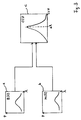
- Fig. 3 shows a flow chart with graphs depicting the shift of the wavelength due to a change of a physical parameter in the ambience of a sensor according to an embodiment of the present invention.
- Box a shows a graph depicting the resulting reference response signal R( ⁇ ) of a measurement of the optical power of a reference response signal of a sensor versus wavelength ⁇ at a known value of the physical parameter for calibration purposes.
- Box b shows a graph depicting the resulting response signal M( ⁇ ) of a measurement of the optical power of a response signal of a sensor versus wavelength ⁇ at a value of the physical parameter which value is to be determined.
- Box c shows a graph depicting the cross correlation function CCF( ⁇ ) of the reference response signal R( ⁇ ) and the response signal M( ⁇ ).
- the wavelength shift ⁇ is evaluated by the evaluation unit 18 by determining the location of the peak of the cross correlation function CCF( ⁇ ) as the integral of the product (R( ⁇ ) M( ⁇ + ⁇ )) from a ⁇ start to a ⁇ stop.
Landscapes
- Physics & Mathematics (AREA)
- General Physics & Mathematics (AREA)
- Chemical & Material Sciences (AREA)
- Engineering & Computer Science (AREA)
- Chemical Kinetics & Catalysis (AREA)
- Plasma & Fusion (AREA)
- Health & Medical Sciences (AREA)
- Life Sciences & Earth Sciences (AREA)
- Analytical Chemistry (AREA)
- Biochemistry (AREA)
- General Health & Medical Sciences (AREA)
- Immunology (AREA)
- Pathology (AREA)
- Optical Transform (AREA)
Abstract
Description
- The present invention relates to optical sensing of a physical parameter of an optical device.
- Optical sensing can be used for example for sensing the temperature or another physical parameter of an ambience in which the optical sensing of the physical parameter takes place.
- Optical sensing means that a change of the physical parameter of interest changes the optical properties of an optical device or sensor used for the optical sensing. Therefore, measuring such a change of the optical properties of the optical device gives information about the change of the physical parameter of interest in the ambience of the optical device.
- It is an object of the invention to provide improved optical sensing of a physical parameter of interest.
- The object is solved by the independent claims.
- In the prior art optical sensing of a physical parameter of an ambience is performed by measuring a wavelength shift of a response signal due to a change of the physical parameter. The response signal is received from an optical device used for the optical sensing and which optical device transmits or reflects a measurement signal launched by a signal generator.
- A transmission or reflection property of such an optical device and hence the wavelength dependency of the response signal is dependent on the physical parameter of interest in the ambience of the optical device. Consequently, such an optical sensor, e.g. an optical fiber sensor, enables the optical sensing of the physical parameter by measuring a change in the wavelength dependence of the response signal due to a change of the physical parameter.
- The invention comprises the perception that measuring the wavelength shift of the response signal with respect to the reference response signal requires exact determination of a characteristic wavelength of these signals. However, normally such signals do not comprise a single peak at a single wavelength but show a more or less noisy spectral distribution. Accordingly, determining a wavelength shift between characteristic wavelengths of response signals e.g. the maximum value or the center of gravity of such spectral responses is difficult and might bear a lot of uncertainty.
- A further problem of the determination of a maximum value is that many measurement points have to be acquired over a wide range to obtain at least some of the measurement points near the maximum to get an accurate result for the location of the maximum and finally for the wavelength at that maximum of the response signals.
- An evaluation according to the present invention is only weakly dependent on the number of measurement points used for the evaluation of the wavelength shift.
- Additionally, the repeatability of an evaluation according to the present invention is also higher than in the methods of the prior art because of the independency of the repeatability from the number of measurement points.
- Moreover, an evaluation according to the present invention is more robust against added noise, e.g. caused by amplifiers or detectors. This is because the influence of added noise in an evaluation of the present invention is only weakly dependent on the number of measurement points.
- E.g. within an optical fiber an optical sensor can preferably be used as a remote sensing device to detect the value of a physical parameter also in a remote distance from a signal generator and a measurement unit.
- Optical sensing according to the present invention can be used for example for sensing the temperature, the pressure, the humidity, the pH value or other physical parameters of an ambience in which the optical sensing of the physical parameter takes place.
- According to a preferred embodiment of the present invention it is used a Bragg grating as an optical device or sensor. The Bragg grating is preferably placed within an optical fiber. The transmission or reflection properties of the Bragg grating change with a change of the physical parameter. Then, the response of the Bragg grating can be detected in transmission and/or in reflection to detect a change of the physical parameter.
- An embodiment of the present invention uses a dye as a sensor to detect a change of the pH of the ambience of the sensor by detecting a change of the dye.
- Other preferred embodiments are shown by the dependent claims.
- The invention can be partly embodied or supported by one or more suitable software programs, which can be stored on or otherwise provided by any kind of data carrier, and which might be executed in or by any suitable data processing unit. Software programs or routines are preferably applied to the realization of the inventive method.
- Other objects and many of the attendant advantages of the present invention will be readily appreciated and become better understood by reference to the following detailed description when considering in connection with the accompanied drawings. The components in the drawings are not necessarily to scale, emphasis instead being placed upon clearly illustrating the principles of the present invention. Features that are substantially or functionally equal or similar will be referred to with the same reference sign(s).
- Fig. 1
- shows a schematic illustration of a first embodiment of the present invention;
- Fig. 2
- shows a schematic illustration of a second embodiment of the present invention; and
- Fig. 3
- shows a flow chart with graphs depicting the shift of the wavelength due to a change of a physical parameter in the ambience of a sensor according to an embodiment of the present invention.
- Referring now in greater detail to the drawing, Fig. 1 shows a schematic illustration of an
apparatus 1 for optical sensing in reflection a value of a physical parameter of an ambience by using an optical signal according to a preferred first embodiment of the present invention. -
Apparatus 1 comprises asignal generator 2 for providing an optical signal to anoptical fiber 4. Theoptical fiber 4 connects thesignal generator 2 with anoptical coupler 6. Theoptical coupler 6 is connected to an optical fiber 8. The optical fiber 8 comprisesoptical devices 10a, 10b and 10c. Theoptical devices 10a, 10b and 10c are integrated in the optical fiber 8 and serve as optical sensors for performing the optical sensing in reflection of a physical parameter of the ambience of theoptical sensors 10a, 10b and 10c, respectively. The physical parameter of the ambience ofoptical sensors 10a, 10b and 10c, respectively, can be the same or each or some of theoptical sensors 10a, 10b and 10c can detect different physical parameters. In thepresent embodiment 1 of Fig. 1 eachoptical sensor 10a, 10b and 10c comprises a reflective Bragg grating. - In a not shown alternative embodiment of the present invention at least one of the sensors use a dye to detect a change of the pH of the ambience of the sensor by detecting a change of the dye in transmission or reflection.
- Physical parameters can be e.g. the temperature, the pressure, the humidity, the pH value or any other physical or chemical parameter.
- By using an optical fiber 8 comprising the
optical sensors 10a, 10b and 10c it is possible to provide a remote sensing device to detect the value of the desired physical parameter in a remote distance from thesignal generator 2. -
Apparatus 1 further comprises anoptical fiber 12, which connects theoptical coupler 6 with ameasurement unit 14. Themeasurement unit 14 comprises a central processing unit (CPU) 13 for performing any necessary calculation processes and comprises amemory 15 for storing information.CPU 13 andmemory 15 are connected with each other and work together in a usual manner. Themeasurement unit 14 serves for measuring an optical signal induced response signal of theoptical devices 10a, 10b and 10c.Measurement unit 14 measures the response signal of theoptical devices 10a, 10b and 10c versus wavelength. In the present embodiment this is done in two steps; firstly in a calibration step and secondly in a measurement step. In the first step there is generated a reference response signal, and in the second step there is generated a measurement response signal. The steps are further described below when howembodiment 1 works to determine the physical parameter. - In the
embodiment 1 Fig. 1optical devices 10a, 10b and 10c do reflect the optical signal generated by thesignal generator 2. However, in alternative embodiments it is also possible to provide an optical fiber 8, which comprises optical sensors which transmit the optical signal ofsignal generator 2. An example of such an embodiment is described below. - Connected with the
measurement unit 14 by anotheroptical fiber 16 is aevaluation unit 18 for calculating a cross correlation function of the reference response signal with the measurement response signal to evaluate a wavelength shift of the measurement response signal with respect to the reference response signal, and for determining the value of the physical parameter by using the evaluated wavelength shift and the known dependency of a wavelength shift of the response signal of theoptical device 10a, 10b and 10c on a shift of the physical parameter. - An alternative second embodiment of the present invention, which transmits the optical signal of
signal generator 2 as mentioned above, is shown in Fig. 2. Fig. 2 shows a schematic illustration of anapparatus 101 for optical sensing in transmission a value of a physical parameter of an ambience by using an optical signal. Differing fromapparatus 1 of Fig. 1apparatus 101 of Fig. 2 comprises adifferent coupler 106 which as two connections 106a and 106b with anoptical fiber 108. Connection 106a serves to guide an optical signal coming fromsignal generator 2 via thecoupler 106 into theoptical fiber 108. Connection 106b serves to guide an optical signal coming back from theoptical fiber 108 into thecoupler 106. Theoptical fiber 108 comprisesoptical devices 110a, 110b and 110c. Theoptical devices 110a, 110b and 110c are integrated in theoptical fiber 108 and serve as optical sensors for performing the optical sensing in transmission of a physical parameter of the ambience of theoptical sensors 110a, 110b and 110c, respectively. The physical parameter of the ambience ofoptical sensors 110a, 110b and 110c, respectively, can be the same or each or some of theoptical sensors 110a, 110b and 110c can detect different physical parameters. Inembodiment 2 of Fig. 2 eachoptical sensor 110a, 110b and 110c comprises a transmittive Bragg grating. - All other parts of
apparatus 101 of Fig. 2 are substantially or functionally equal or similar to the parts ofapparatus 1 of Fig. 1. - The whole process, in particular the calculation of the cross correlation function and the determination of the value of the physical parameter with both
embodiments - An optical signal is generated by the
signal generator 2. The optical signal is transmitted by theoptical fiber 4 to theoptical coupler optical coupler 6 couples the optical signal into theoptical fiber 8 or 108.Optical sensors 10a, 10b and 10c of the optical fiber 8 oroptical sensors 110a, 110b and 110c of theoptical fiber 108 have a known dependency of a wavelength shift of their optical signal induced response signals on a shift of the physical parameter to be measured. - To perform the measurement the
signal generator 2 sweeps the wavelength of the optical signal at a known value of the physical parameter to be measured by theoptical devices measurement unit 14 measures a corresponding reference response signal of theoptical devices - Having done this calibration step the measured reference response signal versus wavelength is stored in the
evaluation unit 18. - To measure a value of the physical parameter which value is to be determined there is performed another sweep of the wavelength by the
signal generator 2 and another measurement of the corresponding response signal of theoptical devices measurement unit 14. The result is also provided to theevaluation unit 18. - The
evaluation unit 18 then uses the stored reference response signal and the stored measurement response signal for calculating a cross correlation function of the reference response signal with the measurement response signal to evaluate a wavelength shift of the measurement response signal with respect to the reference response signal. - If R(λ) is the reference response signal and M(λ) is the measurement response signal, then the cross correlation function CCF(Δλ) is the integral of the product (R(λ) M(λ+Δλ)) from λstart to λstop. The cross correlation function CCF(Δλ) can be calculated batch-bulk, e.g. from λstart1 to λstop1 and then form λstop1 to λstop2. The
evaluation unit 18 is evaluating the wavelength shift Δλ by determining the location of the peak of the cross correlation function CCF(Δλ), the location of the peak indicating the value of the wavelength shift Δλ. - Subsequently, the
evaluation unit 18 determines the value of the physical parameter by using each the evaluated wavelength shift Δλ and the known dependency of a wavelength shift Δλ of the response signal of theoptical devices - In
embodiment 1 of Fig. 1 the optical sensing of a value of a physical parameter is performed at different spatial locations along the optical fiber 8 by way of example using threeoptical devices 10a, 10b and 10c. Inembodiment 101 of Fig. 2 the optical sensing of a value of a physical parameter is performed at different spatial locations along theoptical fiber 108 by using threeoptical devices 110a, 110b and 110c. - Instead of detecting only one response signal when using one optical device, there are three subsequent responses. For each response, a correlation measurement is performed. If the same physical parameter is to be determined and if the optical devices are similar, the correlation is each performed with the same reference response signal. It is also possible to detect a relative shift of the physical parameter at two measurement points by performing a cross correlation between two response signals of the corresponding optical devices.
- To allocate each measurement response signal to a certain location the
evaluation unit 18 performs a time resolution of the measured response signals when detecting the response signals of the threeoptical devices - The
measurement unit 14 can comprise a broadband optical detector when using a narrowband optical signal with variable wavelength provided by thesignal generator 2. - In an alternative embodiment, the
measurement unit 14 can comprise a narrowband optical detector with variable detection wavelength when using a broadband optical signal provided by thesignal generator 2. Instead of sweeping thesignal generator 2, the detector then scans the response within the interested wavelength range. - Further alternatively, the
measurement unit 14 can comprise a narrowband optical detector when using a narrowband optical signal provided by thesignal generator 2, when both bands having substantially the same wavelength. - Fig. 3 shows a flow chart with graphs depicting the shift of the wavelength due to a change of a physical parameter in the ambience of a sensor according to an embodiment of the present invention.
- Box a shows a graph depicting the resulting reference response signal R(λ) of a measurement of the optical power of a reference response signal of a sensor versus wavelength λ at a known value of the physical parameter for calibration purposes.
- Box b shows a graph depicting the resulting response signal M(λ) of a measurement of the optical power of a response signal of a sensor versus wavelength λ at a value of the physical parameter which value is to be determined.
- Box c shows a graph depicting the cross correlation function CCF(Δλ) of the reference response signal R(λ) and the response signal M(λ). As described above the wavelength shift Δλ is evaluated by the
evaluation unit 18 by determining the location of the peak of the cross correlation function CCF(Δλ) as the integral of the product (R(λ) M(λ+Δλ)) from a λstart to a λstop.
Claims (15)
whereby the optical device (10a, 10b, 10c) is integrated in an optical fiber (8) connected to the measurement unit.
whereby the optical device (10a, 10b, 10c) comprises a Bragg grating.
whereby the device (10a, 10b, 10c) comprises a dye.
Priority Applications (1)
| Application Number | Priority Date | Filing Date | Title |
|---|---|---|---|
| EP04103883A EP1626259A1 (en) | 2004-08-12 | 2004-08-12 | Optical sensing of a physical parameter |
Applications Claiming Priority (1)
| Application Number | Priority Date | Filing Date | Title |
|---|---|---|---|
| EP04103883A EP1626259A1 (en) | 2004-08-12 | 2004-08-12 | Optical sensing of a physical parameter |
Publications (1)
| Publication Number | Publication Date |
|---|---|
| EP1626259A1 true EP1626259A1 (en) | 2006-02-15 |
Family
ID=34929441
Family Applications (1)
| Application Number | Title | Priority Date | Filing Date |
|---|---|---|---|
| EP04103883A Withdrawn EP1626259A1 (en) | 2004-08-12 | 2004-08-12 | Optical sensing of a physical parameter |
Country Status (1)
| Country | Link |
|---|---|
| EP (1) | EP1626259A1 (en) |
Cited By (2)
| Publication number | Priority date | Publication date | Assignee | Title |
|---|---|---|---|---|
| CN102507449A (en) * | 2011-11-29 | 2012-06-20 | 中国计量学院 | Temperature-insensitive light source self-correcting humidity sensor based on TFBG (tilted fiber Bragg grating) |
| WO2015181155A1 (en) * | 2014-05-26 | 2015-12-03 | Danmarks Tekniske Universitet | Optical sensor for measuring humidity, strain and temperature |
Citations (2)
| Publication number | Priority date | Publication date | Assignee | Title |
|---|---|---|---|---|
| US5798521A (en) * | 1996-02-27 | 1998-08-25 | The United States Of America As Represented By The Administrator Of The National Aeronautics And Space Administration | Apparatus and method for measuring strain in bragg gratings |
| US6545760B1 (en) * | 1999-03-25 | 2003-04-08 | The United States Of America As Represented By The Administrator Of The National Aeronautics And Space Administration | Apparatus and method for measuring strain in optical fibers using rayleigh scatter |
-
2004
- 2004-08-12 EP EP04103883A patent/EP1626259A1/en not_active Withdrawn
Patent Citations (2)
| Publication number | Priority date | Publication date | Assignee | Title |
|---|---|---|---|---|
| US5798521A (en) * | 1996-02-27 | 1998-08-25 | The United States Of America As Represented By The Administrator Of The National Aeronautics And Space Administration | Apparatus and method for measuring strain in bragg gratings |
| US6545760B1 (en) * | 1999-03-25 | 2003-04-08 | The United States Of America As Represented By The Administrator Of The National Aeronautics And Space Administration | Apparatus and method for measuring strain in optical fibers using rayleigh scatter |
Cited By (2)
| Publication number | Priority date | Publication date | Assignee | Title |
|---|---|---|---|---|
| CN102507449A (en) * | 2011-11-29 | 2012-06-20 | 中国计量学院 | Temperature-insensitive light source self-correcting humidity sensor based on TFBG (tilted fiber Bragg grating) |
| WO2015181155A1 (en) * | 2014-05-26 | 2015-12-03 | Danmarks Tekniske Universitet | Optical sensor for measuring humidity, strain and temperature |
Similar Documents
| Publication | Publication Date | Title |
|---|---|---|
| US5945666A (en) | Hybrid fiber bragg grating/long period fiber grating sensor for strain/temperature discrimination | |
| EP0190001B1 (en) | Temperature measurement | |
| US6577402B1 (en) | Sensor and method for measuring changes in environmental conditions | |
| CN102292621B (en) | Improvements in Distributed Fiber Optic Sensing | |
| EP1506373B1 (en) | Fibre-optic interferometric remote sensor | |
| US20100128756A1 (en) | Dual source auto-correction in distributed temperature systems | |
| CN107515033B (en) | Point type liquid level sensor device and its measurement method based on optical frequency domain reflection technology | |
| CN116105775B (en) | A method for high-speed demodulation and real-time verification of cavity length of optical fiber Fabry-Perot sensor | |
| US8576387B2 (en) | Fiber identification using optical frequency-domain reflectometer | |
| EA024802B1 (en) | Distributed fibre optic acoustic sensor and method for determining direction and/or distance of the origin of an acoustic wave in distributed fibre optic acoustic sensing using said sensor | |
| CN109238321B (en) | Phase-sensitive optical time domain reflectometer based on multi-frequency time domain correlation and measuring method | |
| CN114838745B (en) | Single-data-channel multi-light-path parallel sensing method and system | |
| GB2414796A (en) | Optical wavelength determination using multiple measurable features | |
| JP4726433B2 (en) | Apparatus and method for identifying surface properties | |
| US6659640B2 (en) | Fiber optic temperature measurement system and method | |
| JPS63140927A (en) | Distribution temperature sensor | |
| JP4102291B2 (en) | OFDR system continuous strain measurement system | |
| AU2019361360A1 (en) | Temperature monitoring device, temperature monitoring method, and temperature monitoring system | |
| JP6706192B2 (en) | Propagation delay time difference measuring method between spatial channels and propagation delay time difference measuring apparatus between spatial channels | |
| EP1807686A1 (en) | Optical time domain reflectometry for determining distributed physical properties | |
| CN112229501A (en) | Vibration signal automatic detection device and method based on OFDR | |
| JP2002082048A (en) | Non-contact physical property measuring method and device | |
| US7312435B2 (en) | Determination of a physical state of an optical device | |
| CN116793239A (en) | Optical fiber strain determining method and device based on phase demodulation and electronic equipment | |
| CN111257283B (en) | Refractive index sensing measurement device and method |
Legal Events
| Date | Code | Title | Description |
|---|---|---|---|
| PUAI | Public reference made under article 153(3) epc to a published international application that has entered the european phase |
Free format text: ORIGINAL CODE: 0009012 |
|
| AK | Designated contracting states |
Kind code of ref document: A1 Designated state(s): AT BE BG CH CY CZ DE DK EE ES FI FR GB GR HU IE IT LI LU MC NL PL PT RO SE SI SK TR |
|
| AX | Request for extension of the european patent |
Extension state: AL HR LT LV MK |
|
| AKX | Designation fees paid | ||
| RAP1 | Party data changed (applicant data changed or rights of an application transferred) |
Owner name: AGILENT TECHNOLOGIES, INC. |
|
| REG | Reference to a national code |
Ref country code: DE Ref legal event code: 8566 |
|
| STAA | Information on the status of an ep patent application or granted ep patent |
Free format text: STATUS: THE APPLICATION IS DEEMED TO BE WITHDRAWN |
|
| 18D | Application deemed to be withdrawn |
Effective date: 20060817 |