EP1626234A2 - Icemaker - Google Patents
Icemaker Download PDFInfo
- Publication number
- EP1626234A2 EP1626234A2 EP05107457A EP05107457A EP1626234A2 EP 1626234 A2 EP1626234 A2 EP 1626234A2 EP 05107457 A EP05107457 A EP 05107457A EP 05107457 A EP05107457 A EP 05107457A EP 1626234 A2 EP1626234 A2 EP 1626234A2
- Authority
- EP
- European Patent Office
- Prior art keywords
- ice cube
- cube tray
- icemaker
- ultrasonic vibrator
- ice
- Prior art date
- Legal status (The legal status is an assumption and is not a legal conclusion. Google has not performed a legal analysis and makes no representation as to the accuracy of the status listed.)
- Withdrawn
Links
Images

Classifications
-
- F—MECHANICAL ENGINEERING; LIGHTING; HEATING; WEAPONS; BLASTING
- F25—REFRIGERATION OR COOLING; COMBINED HEATING AND REFRIGERATION SYSTEMS; HEAT PUMP SYSTEMS; MANUFACTURE OR STORAGE OF ICE; LIQUEFACTION SOLIDIFICATION OF GASES
- F25C—PRODUCING, WORKING OR HANDLING ICE
- F25C1/00—Producing ice
- F25C1/18—Producing ice of a particular transparency or translucency, e.g. by injecting air
-
- F—MECHANICAL ENGINEERING; LIGHTING; HEATING; WEAPONS; BLASTING
- F25—REFRIGERATION OR COOLING; COMBINED HEATING AND REFRIGERATION SYSTEMS; HEAT PUMP SYSTEMS; MANUFACTURE OR STORAGE OF ICE; LIQUEFACTION SOLIDIFICATION OF GASES
- F25C—PRODUCING, WORKING OR HANDLING ICE
- F25C1/00—Producing ice
- F25C1/18—Producing ice of a particular transparency or translucency, e.g. by injecting air
- F25C1/20—Producing ice of a particular transparency or translucency, e.g. by injecting air by agitation
-
- F—MECHANICAL ENGINEERING; LIGHTING; HEATING; WEAPONS; BLASTING
- F25—REFRIGERATION OR COOLING; COMBINED HEATING AND REFRIGERATION SYSTEMS; HEAT PUMP SYSTEMS; MANUFACTURE OR STORAGE OF ICE; LIQUEFACTION SOLIDIFICATION OF GASES
- F25C—PRODUCING, WORKING OR HANDLING ICE
- F25C1/00—Producing ice
- F25C1/22—Construction of moulds; Filling devices for moulds
-
- F—MECHANICAL ENGINEERING; LIGHTING; HEATING; WEAPONS; BLASTING
- F25—REFRIGERATION OR COOLING; COMBINED HEATING AND REFRIGERATION SYSTEMS; HEAT PUMP SYSTEMS; MANUFACTURE OR STORAGE OF ICE; LIQUEFACTION SOLIDIFICATION OF GASES
- F25C—PRODUCING, WORKING OR HANDLING ICE
- F25C5/00—Working or handling ice
- F25C5/02—Apparatus for disintegrating, removing or harvesting ice
- F25C5/04—Apparatus for disintegrating, removing or harvesting ice without the use of saws
- F25C5/06—Apparatus for disintegrating, removing or harvesting ice without the use of saws by deforming bodies with which the ice is in contact, e.g. using inflatable members
-
- F—MECHANICAL ENGINEERING; LIGHTING; HEATING; WEAPONS; BLASTING
- F25—REFRIGERATION OR COOLING; COMBINED HEATING AND REFRIGERATION SYSTEMS; HEAT PUMP SYSTEMS; MANUFACTURE OR STORAGE OF ICE; LIQUEFACTION SOLIDIFICATION OF GASES
- F25C—PRODUCING, WORKING OR HANDLING ICE
- F25C1/00—Producing ice
- F25C1/10—Producing ice by using rotating or otherwise moving moulds
-
- F—MECHANICAL ENGINEERING; LIGHTING; HEATING; WEAPONS; BLASTING
- F25—REFRIGERATION OR COOLING; COMBINED HEATING AND REFRIGERATION SYSTEMS; HEAT PUMP SYSTEMS; MANUFACTURE OR STORAGE OF ICE; LIQUEFACTION SOLIDIFICATION OF GASES
- F25C—PRODUCING, WORKING OR HANDLING ICE
- F25C2305/00—Special arrangements or features for working or handling ice
- F25C2305/022—Harvesting ice including rotating or tilting or pivoting of a mould or tray
- F25C2305/0221—Harvesting ice including rotating or tilting or pivoting of a mould or tray rotating ice mould
Definitions
- the present invention relates to an icemaker, comprising an ice cube tray comprising a plurality of depressions for holding water; and an ultrasonic vibrator.
- an icemaker is used to freeze water, and is widely employed in household appliances such as refrigerators and water purifiers.
- the quality of the icemaker is determined according to the transparency and strength of the ice made thereby.
- a conventional icemaker includes an ice cube tray, a water supply to supply water into the ice cube tray, and a driver to twist the ice cube tray to release the ice from the ice cube tray.
- a conventional icemaker also includes an ice reservoir to receive the ice that has fallen from the ice cube tray and an air-removing unit to remove air from water in the ice cube tray.
- An icemaker which undulates the water filled in the ice cube tray includes a reciprocating unit to reciprocate the ice cube tray or an ultrasonic vibrator to directly vibrate the water. Icemakers including the reciprocating unit and ultrasonic vibrator are disclosed in Korean Patent Application Nos. 1995-18572 and 2001-26283, respectively
- the structure of the reciprocating unit can be complicated and difficult to install. Also, the efficiency of removing the air from water filled in the ice cube tray may not be good.
- the structure of the ultrasonic vibrator is relatively simple. However, ultrasonic vibration of the ultrasonic vibrator is not uniformly applied to the water filled in the ice cube tray and partitioned into a plurality of cubes. Thus, the efficiency of removing the air from water filled in the ice cube tray is not uniform.
- the invention is characterized in that the ultrasonic vibrator is operable to apply ultrasonic vibrations directly to the ice cube tray.
- an icemaker includes an ice cube tray 20 formed with a plurality of depressions 22, a driver 30 coupled with the ice cube tray 20, to rotate the ice cube tray 20, and a stopper 40 to contact one end of the rotated ice cube tray 20 to cause the ice cube tray 20 to be twisted.
- the icemaker also includes a supporting bracket 50 to support the ice cube tray 20 and the driver 30, an ice reservoir 60 placed under the ice cube tray 20 to receive ice released from the ice cube tray 20, and an ultrasonic vibrator 70 coupled to the ice cube tray 20, to vibrate the ice cube tray 20.
- the ice cube tray 20 has a rectangular shape, and its opposite sides thereof are provided with a driver coupling groove 24 to be coupled with a rotating shaft (not shown) of the driver 30.
- the ice cube tray 20 also includes a supporting shaft 26 to be stably and rotatably supported in the supporting bracket 50.
- the plurality of depressions 22 of the ice cube tray 20 are arranged along longitudinal and transverse directions, allowing the ice cube tray 20 to make a plurality of ice-cubes. Ice may be released from the depression 22 when the driver 30 rotates and twists the ice cube tray 20.
- the driver 30 includes a motor (not shown) to generate a rotational force.
- the driver 30 also includes the rotating shaft (not shown) to connect the motor with the driver coupling groove 24 and to transfer the rotational force from the motor to the ice cube tray 20, rotating the ice cube tray 20 at a predetermined angle.
- the driver 30 may be selected among well-known drivers.
- the stopper 40 is provided in one side of the supporting bracket 50, to stop one side of the ice cube tray 20 from rotating. This causes the ice cube tray 20 to twist.
- the shape and position of the stopper may vary as long as the ice cube tray 20 can be supported and twisted.
- the supporting bracket 50 is connected to the ice cube tray 20 and the driver 30.
- the supporting bracket 50 has a supporting shaft coupling groove 52 at one side to which the supporting shaft 26 of the ice cube tray 20 is coupled and supported.
- the ultrasonic vibrator 70 vibrates the ice cube tray 20 and indirectly undulates water filled in the depressions 22 of the ice cube tray 20, discharging air from the water. Thus, the air is uniformly removed from the water filled in the depressions 22 of the ice cube tray 20.
- the ultrasonic vibrator 70 is attached to an outer side of the ice cube tray 20.
- the position of the ultrasonic vibrator may vary as long as it causes the ice cube tray to vibrate. Further, more than one ultrasonic vibrator may be provided.
- the ultrasonic vibrator may be detachably provided in the ice cube tray 20. Therefore, when the quality of the ice is not important, for example, when shattered ice is needed, the ultrasonic vibrator may be detached from the ice cube tray 20.
- the depressions 22 of the ice cube tray 20 are filled with water supplied from a water supply. Then, the water filled in the depressions 22 is frozen by driving a freezing unit (not shown). While the water is being frozen, the ultrasonic vibrator 70 vibrates the ice cube tray 20, discharging air from the water.
- the driver 30 drives the ice cube tray 20 in order to release the ice from the depressions 22.
- the ice cube tray 20 rotates to a predetermined angle and contacts the stopper 40 provided in one side of the supporting bracket 50.
- the driver 30 continues to drive the ice cube tray 20 to rotate in a state whilst one side of the ice cube tray 20 is stopped by the stopper 40 so the other side thereof continues to rotate, thereby twisting the ice cube tray 20.
- the ice is released from the depressions 22 and falls into the ice reservoir 60 placed under the ice cube tray 20.
- the icemaker twists the ice cube tray 20 to release the ice from the ice cube tray 20.
- the ultrasonic vibrator may be applied to an icemaker that includes a heater and an ice-releasing blade to release the ice from the ice cube tray. In this case, the ultrasonic vibrator should be placed such that it is not affected by the heater.
- the present invention provides an icemaker in which an ultrasonic vibrator is attached to an ice cube tray, so that the ultrasonic vibrator is easily installed and air is uniformly discharged from water filled in cubes of the ice cube tray, enhancing the transparency and the strength of the ice.
Landscapes
- Engineering & Computer Science (AREA)
- Physics & Mathematics (AREA)
- Mechanical Engineering (AREA)
- Thermal Sciences (AREA)
- General Engineering & Computer Science (AREA)
- Production, Working, Storing, Or Distribution Of Ice (AREA)
- Devices That Are Associated With Refrigeration Equipment (AREA)
Abstract
Description
- The present invention relates to an icemaker, comprising an ice cube tray comprising a plurality of depressions for holding water; and an ultrasonic vibrator.
- Generally, an icemaker is used to freeze water, and is widely employed in household appliances such as refrigerators and water purifiers. The quality of the icemaker is determined according to the transparency and strength of the ice made thereby.
- A conventional icemaker includes an ice cube tray, a water supply to supply water into the ice cube tray, and a driver to twist the ice cube tray to release the ice from the ice cube tray. A conventional icemaker also includes an ice reservoir to receive the ice that has fallen from the ice cube tray and an air-removing unit to remove air from water in the ice cube tray.
- When an icemaking process begins, the water is first frozen at a surface thereof. Thus, air present in the water cannot be discharged from the water. The air included in the ice reduces the transparency and the strength of the ice, thereby causing the ice to be easily broken when the ice is released from the ice cube tray. To solve this problem, there has been used a method of undulating the water filled in the ice cube tray. An icemaker which undulates the water filled in the ice cube tray includes a reciprocating unit to reciprocate the ice cube tray or an ultrasonic vibrator to directly vibrate the water. Icemakers including the reciprocating unit and ultrasonic vibrator are disclosed in Korean Patent Application Nos. 1995-18572 and 2001-26283, respectively
- The structure of the reciprocating unit can be complicated and difficult to install. Also, the efficiency of removing the air from water filled in the ice cube tray may not be good.
- The structure of the ultrasonic vibrator is relatively simple. However, ultrasonic vibration of the ultrasonic vibrator is not uniformly applied to the water filled in the ice cube tray and partitioned into a plurality of cubes. Thus, the efficiency of removing the air from water filled in the ice cube tray is not uniform.
- Accordingly, it is an aim of the present invention to provide an icemaker in which air included in water filled in cubes of an ice cube tray is more uniformly removed.
- The invention is characterized in that the ultrasonic vibrator is operable to apply ultrasonic vibrations directly to the ice cube tray.
- Embodiments of the present invention will now be described with reference to the accompany drawings of which:
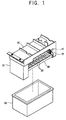
- Figure 1 is a perspective view of one embodiment of an icemaker according to the present invention;
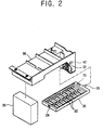
- Figure 2 is an exploded perspective view of the icemaker of Figure 1;
- Figure 3 is a perspective view illustrating an operation of the icemaker of Figure 1; and
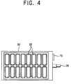
- Figure 4 is a plan view of an ice cube tray of the icemaker of Figure 2.
- As shown in Figures 1 through 4, an icemaker includes an
ice cube tray 20 formed with a plurality ofdepressions 22, adriver 30 coupled with theice cube tray 20, to rotate theice cube tray 20, and astopper 40 to contact one end of the rotatedice cube tray 20 to cause theice cube tray 20 to be twisted. - The icemaker also includes a supporting
bracket 50 to support theice cube tray 20 and thedriver 30, anice reservoir 60 placed under theice cube tray 20 to receive ice released from theice cube tray 20, and anultrasonic vibrator 70 coupled to theice cube tray 20, to vibrate theice cube tray 20. - The
ice cube tray 20 has a rectangular shape, and its opposite sides thereof are provided with adriver coupling groove 24 to be coupled with a rotating shaft (not shown) of thedriver 30. Theice cube tray 20 also includes a supportingshaft 26 to be stably and rotatably supported in the supportingbracket 50. - The plurality of
depressions 22 of theice cube tray 20 are arranged along longitudinal and transverse directions, allowing theice cube tray 20 to make a plurality of ice-cubes. Ice may be released from thedepression 22 when thedriver 30 rotates and twists theice cube tray 20. - The
driver 30 includes a motor (not shown) to generate a rotational force. Thedriver 30 also includes the rotating shaft (not shown) to connect the motor with thedriver coupling groove 24 and to transfer the rotational force from the motor to theice cube tray 20, rotating theice cube tray 20 at a predetermined angle. Thedriver 30 may be selected among well-known drivers. - The
stopper 40 is provided in one side of the supportingbracket 50, to stop one side of theice cube tray 20 from rotating. This causes theice cube tray 20 to twist. The shape and position of the stopper may vary as long as theice cube tray 20 can be supported and twisted. - The supporting
bracket 50 is connected to theice cube tray 20 and thedriver 30. The supportingbracket 50 has a supportingshaft coupling groove 52 at one side to which the supportingshaft 26 of theice cube tray 20 is coupled and supported. - The
ultrasonic vibrator 70 vibrates theice cube tray 20 and indirectly undulates water filled in thedepressions 22 of theice cube tray 20, discharging air from the water. Thus, the air is uniformly removed from the water filled in thedepressions 22 of theice cube tray 20. - The
ultrasonic vibrator 70 is attached to an outer side of theice cube tray 20. The position of the ultrasonic vibrator may vary as long as it causes the ice cube tray to vibrate. Further, more than one ultrasonic vibrator may be provided. - Also, the ultrasonic vibrator may be detachably provided in the
ice cube tray 20. Therefore, when the quality of the ice is not important, for example, when shattered ice is needed, the ultrasonic vibrator may be detached from theice cube tray 20. - According to the configuration above, operations of the icemaker will now be described with respect to Figure 3.
- First, the
depressions 22 of theice cube tray 20 are filled with water supplied from a water supply. Then, the water filled in thedepressions 22 is frozen by driving a freezing unit (not shown). While the water is being frozen, theultrasonic vibrator 70 vibrates theice cube tray 20, discharging air from the water. - When the water has frozen, the
driver 30 drives theice cube tray 20 in order to release the ice from thedepressions 22. The ice cube tray 20 rotates to a predetermined angle and contacts thestopper 40 provided in one side of the supportingbracket 50. - The
driver 30 continues to drive theice cube tray 20 to rotate in a state whilst one side of theice cube tray 20 is stopped by thestopper 40 so the other side thereof continues to rotate, thereby twisting theice cube tray 20. Thus, the ice is released from thedepressions 22 and falls into theice reservoir 60 placed under theice cube tray 20. - In the above-described embodiment, the the icemaker twists the
ice cube tray 20 to release the ice from theice cube tray 20. However, the ultrasonic vibrator may be applied to an icemaker that includes a heater and an ice-releasing blade to release the ice from the ice cube tray. In this case, the ultrasonic vibrator should be placed such that it is not affected by the heater. - As described above, the present invention provides an icemaker in which an ultrasonic vibrator is attached to an ice cube tray, so that the ultrasonic vibrator is easily installed and air is uniformly discharged from water filled in cubes of the ice cube tray, enhancing the transparency and the strength of the ice.
- Although embodiments of the present invention have been shown and described, it will be appreciated by those skilled in the art that changes may be made in these embodiments without departing from the principles of the invention, the scope of which is defined in the appended claims.
Claims (17)
- An icemaker, comprising:an ice cube tray (20) comprising a plurality of depressions (22) for holding water; andan ultrasonic vibrator (70),characterized in that the ultrasonic vibrator is operable to apply ultrasonic vibrations directly to the ice cube tray.
- An icemaker as claimed in claim 1, wherein the ultrasonic vibrator is coupled directly to the ice cube tray.
- An icemaker as claimed in claim 2, wherein the ultrasonic vibrator is attached to the outside of the ice cube tray.
- An icemaker as claimed in claim 2 or claim 3, wherein the ultrasonic vibrator is detachable from the ice cube tray.
- An icemaker to freeze water into ice, comprising:an ice cube tray formed with cubes to be filled with the water; andan ultrasonic vibrator attached to the ice cube tray, to apply ultrasonic vibration to the ice cube tray to undulate the water filled in the cubes.
- The icemaker according to claim 5, wherein the ultrasonic vibrator is attached to an outer side of the ice cube tray.
- The icemaker according to claim 5, wherein the ultrasonic vibrator is detachably provided in the ice cube tray.
- The icemaker according to claim 7, wherein the ultrasonic vibrator is detachably provided in the ice cube tray.
- The icemaker according to claim 5, wherein the ultrasonic vibrator is plurally provided in the ice cube tray.
- An icemaker, comprising:an ice cube tray formed with a plurality of cubes to be filled with water;a driver coupled to the ice cube tray, to rotate the ice cube tray;a stopper to contact one end of the rotated ice cube tray, to cause the ice cube tray to be twisted;a supporting bracket to support the ice cube tray and driver;an ice reservoir placed under the ice cube tray, to receive ice released from the ice cube tray; andan ultrasonic vibrator coupled to the ice cube tray, to vibrate the ice cube tray and undulate the water filled in the cubes.
- The icemaker according to claim 10, further comprising:a rotational shaft provided in the driver;a driver coupling groove coupled with a rotational shaft of the driver; anda motor provided in the driver, to generate a rotational force,wherein the rotational shaft connects the motor with the driver coupling groove and transfers the rotational force from the motor to the ice cube tray, rotating the ice cube tray at a predetermined angle.
- The icemaker according to claim 11, further comprising:a supporting shaft stably and rotatably supported in the supporting bracket.
- The icemaker according to claim 12, wherein the supporting bracket comprises:a supporting shaft coupling groove at one side of the supporting bracket to which the supporting shaft is coupled and supported, the supporting bracket being connected to the ice cube tray and the driver.
- The icemaker according to claim 10, wherein the stopper is provided in one side of the supporting bracket, to stop one side of the ice cube tray from rotating, twisting the ice cube tray.
- The icemaker according to claim 10, wherein the driver drives the ice cube tray to rotate in a state in which one side of the ice cube tray is supported by the stopper, one side of the ice cube tray is stopped by the stopper, and an other side continues to rotate, twisting the ice cube tray.
- The icemaker according to claim 10, wherein the ultrasonic vibrator is detachably provided in the ice cube tray.
- The icemaker according to claim 10, wherein the ultrasonic vibrator is plurally provided in the ice cube tray.
Applications Claiming Priority (1)
| Application Number | Priority Date | Filing Date | Title |
|---|---|---|---|
| KR1020040063617A KR20060014891A (en) | 2004-08-12 | 2004-08-12 | Ice maker |
Publications (2)
| Publication Number | Publication Date |
|---|---|
| EP1626234A2 true EP1626234A2 (en) | 2006-02-15 |
| EP1626234A3 EP1626234A3 (en) | 2006-06-07 |
Family
ID=36076748
Family Applications (1)
| Application Number | Title | Priority Date | Filing Date |
|---|---|---|---|
| EP05107457A Withdrawn EP1626234A3 (en) | 2004-08-12 | 2005-08-12 | Icemaker |
Country Status (5)
| Country | Link |
|---|---|
| US (1) | US20060032262A1 (en) |
| EP (1) | EP1626234A3 (en) |
| JP (1) | JP2006052935A (en) |
| KR (1) | KR20060014891A (en) |
| CN (1) | CN1734219A (en) |
Families Citing this family (29)
| Publication number | Priority date | Publication date | Assignee | Title |
|---|---|---|---|---|
| KR100868347B1 (en) * | 2007-02-12 | 2008-11-13 | 엘지전자 주식회사 | Refrigerator ice maker |
| NL1034074C2 (en) | 2007-07-02 | 2009-01-05 | Schoonen Beheer B V W | Device and method for manufacturing ice cubes. |
| KR100906914B1 (en) * | 2007-09-13 | 2009-07-08 | 엘지전자 주식회사 | Power transmission gear and ice maker assembly for refrigerator using the same |
| DE202007014786U1 (en) * | 2007-10-23 | 2009-03-05 | Liebherr-Hausgeräte Lienz Gmbh | Ice cube tray and refrigerator and / or freezer with such an ice cube tray |
| US20120047918A1 (en) * | 2010-08-25 | 2012-03-01 | Herrera Carlos A | Piezoelectric harvest ice maker |
| US9903631B2 (en) | 2012-04-20 | 2018-02-27 | Bsh Home Appliances Corporation | Refrigerator and ice making device for producing and releasing clear ice, and method thereof |
| US9513045B2 (en) * | 2012-05-03 | 2016-12-06 | Whirlpool Corporation | Heater-less ice maker assembly with a twistable tray |
| US8925335B2 (en) | 2012-11-16 | 2015-01-06 | Whirlpool Corporation | Ice cube release and rapid freeze using fluid exchange apparatus and methods |
| US9518770B2 (en) | 2012-12-13 | 2016-12-13 | Whirlpool Corporation | Multi-sheet spherical ice making |
| US9557087B2 (en) | 2012-12-13 | 2017-01-31 | Whirlpool Corporation | Clear ice making apparatus having an oscillation frequency and angle |
| US9310115B2 (en) | 2012-12-13 | 2016-04-12 | Whirlpool Corporation | Layering of low thermal conductive material on metal tray |
| US9476629B2 (en) | 2012-12-13 | 2016-10-25 | Whirlpool Corporation | Clear ice maker and method for forming clear ice |
| US9500398B2 (en) | 2012-12-13 | 2016-11-22 | Whirlpool Corporation | Twist harvest ice geometry |
| US9470448B2 (en) | 2012-12-13 | 2016-10-18 | Whirlpool Corporation | Apparatus to warm plastic side of mold |
| US9518773B2 (en) | 2012-12-13 | 2016-12-13 | Whirlpool Corporation | Clear ice maker |
| US9410723B2 (en) | 2012-12-13 | 2016-08-09 | Whirlpool Corporation | Ice maker with rocking cold plate |
| US9759472B2 (en) | 2012-12-13 | 2017-09-12 | Whirlpool Corporation | Clear ice maker with warm air flow |
| EP2807931A1 (en) | 2013-05-28 | 2014-12-03 | W. Schoonen Beheer B.V. | Ice cube maker |
| WO2016065269A2 (en) | 2014-10-23 | 2016-04-28 | Whirlpool Corporation | Method and apparatus for increasing rate of ice production in an automatic ice maker |
| CN105293612A (en) * | 2015-10-17 | 2016-02-03 | 苏州路之遥科技股份有限公司 | Bubble removing water tank with flow detecting function |
| DE102017211714A1 (en) * | 2017-07-10 | 2019-01-10 | BSH Hausgeräte GmbH | Ice maker for a domestic refrigerator with a Ausschiebeeinheit and a twisting device, and household refrigeration appliance and method |
| US10739053B2 (en) | 2017-11-13 | 2020-08-11 | Whirlpool Corporation | Ice-making appliance |
| CN110114624B (en) * | 2017-11-30 | 2021-06-25 | 日本电产三协株式会社 | Ice maker |
| JP7245628B2 (en) * | 2018-10-02 | 2023-03-24 | 日本電産サンキョー株式会社 | ice machine |
| US10907874B2 (en) | 2018-10-22 | 2021-02-02 | Whirlpool Corporation | Ice maker downspout |
| CN112503815A (en) * | 2020-11-18 | 2021-03-16 | 合肥美菱物联科技有限公司 | Ice maker with ultrasonic-assisted freezing function and control method thereof |
| KR102499060B1 (en) * | 2022-05-11 | 2023-02-13 | 윤보민 | Portable refrigerator with ice making function |
| US20250116446A1 (en) * | 2023-10-06 | 2025-04-10 | Bsh Home Appliances Corporation | Twist tray ice making system with slanted bridging |
| CN221666342U (en) * | 2023-12-13 | 2024-09-06 | 台州市黄岩四月塑业有限公司 | An ice removal tool |
Family Cites Families (11)
| Publication number | Priority date | Publication date | Assignee | Title |
|---|---|---|---|---|
| US3224213A (en) * | 1964-07-17 | 1965-12-21 | Jr Earl E Hoyt | Method for making and harvesting ice using ultrasonic vibrators |
| US3451227A (en) * | 1967-10-25 | 1969-06-24 | Gen Motors Corp | Ice maker with oscillating movement during freezing |
| US3696635A (en) * | 1971-04-12 | 1972-10-10 | Gen Motors Corp | Ejecting receptacle for plastic ice tray |
| US4306423A (en) * | 1980-10-09 | 1981-12-22 | General Electric Company | Flexible tray type ice maker |
| US4852359A (en) * | 1988-07-27 | 1989-08-01 | Manzotti Ermanno J | Process and apparatus for making clear ice cubes |
| US5253487A (en) * | 1989-11-15 | 1993-10-19 | Kabushiki Kaisha Toshiba | Automatic ice maker and household refrigerator equipped therewith |
| JP2609741B2 (en) * | 1990-04-26 | 1997-05-14 | 株式会社東芝 | Refrigerator with automatic ice maker |
| JP2727280B2 (en) * | 1992-09-04 | 1998-03-11 | 株式会社三協精機製作所 | Ice tray vibrator |
| KR100389389B1 (en) * | 2000-08-07 | 2003-06-27 | 주식회사 엘지이아이 | The ice-making unit for refrigerators |
| KR20040039091A (en) * | 2002-10-31 | 2004-05-10 | 히데오 나까조 | Ice making machine |
| KR20050077583A (en) * | 2004-01-28 | 2005-08-03 | 삼성전자주식회사 | Ice manufacture apparatus |
-
2004
- 2004-08-12 KR KR1020040063617A patent/KR20060014891A/en not_active Ceased
-
2005
- 2005-06-16 CN CNA2005100781721A patent/CN1734219A/en active Pending
- 2005-06-24 US US11/165,242 patent/US20060032262A1/en not_active Abandoned
- 2005-07-05 JP JP2005196566A patent/JP2006052935A/en not_active Withdrawn
- 2005-08-12 EP EP05107457A patent/EP1626234A3/en not_active Withdrawn
Also Published As
| Publication number | Publication date |
|---|---|
| KR20060014891A (en) | 2006-02-16 |
| EP1626234A3 (en) | 2006-06-07 |
| JP2006052935A (en) | 2006-02-23 |
| CN1734219A (en) | 2006-02-15 |
| US20060032262A1 (en) | 2006-02-16 |
Similar Documents
| Publication | Publication Date | Title |
|---|---|---|
| EP1626234A2 (en) | Icemaker | |
| KR20050077583A (en) | Ice manufacture apparatus | |
| JP4572833B2 (en) | Ice making equipment | |
| CN1207525C (en) | Ice machine | |
| CN1285870C (en) | Ice machine | |
| KR100202064B1 (en) | Ice making machine ice making machine | |
| JP2008196737A (en) | Ice making device and refrigerator with the same | |
| KR20120062498A (en) | Ice maker | |
| CN203824195U (en) | Ice shoveling device | |
| CN1746598A (en) | Refrigerator | |
| KR100254469B1 (en) | Automatic ice making apparatus of refrigerator | |
| KR20000007728U (en) | Ice machine of refrigerator automatic ice maker | |
| KR20060018141A (en) | Ice maker | |
| KR20000011102U (en) | Ice machine of refrigerator automatic ice maker | |
| JP2004301486A (en) | Auger assembly | |
| CN103277953A (en) | Ice maker and refrigerator | |
| CN105605844A (en) | Ice maker and ice making method | |
| KR20000007731U (en) | Ice Separator in Automatic Refrigerator | |
| KR200342122Y1 (en) | Automatic ice-discharging apparatus for refrigerators | |
| KR100301559B1 (en) | Automatic ice maker and refrigerator equipped with the same | |
| KR20000007727U (en) | Ice machine of refrigerator automatic ice maker using hot wire | |
| KR100242325B1 (en) | Ice maker in refrigerator | |
| JP2001041622A (en) | Ice maker and deep freezer refrigerator having the same | |
| CN103119383B (en) | Refrigerator, in particular domestic refrigerator having an ice cube maker | |
| JP2012002382A (en) | Auger type ice making machine |
Legal Events
| Date | Code | Title | Description |
|---|---|---|---|
| PUAI | Public reference made under article 153(3) epc to a published international application that has entered the european phase |
Free format text: ORIGINAL CODE: 0009012 |
|
| AK | Designated contracting states |
Kind code of ref document: A2 Designated state(s): AT BE BG CH CY CZ DE DK EE ES FI FR GB GR HU IE IS IT LI LT LU LV MC NL PL PT RO SE SI SK TR |
|
| AX | Request for extension of the european patent |
Extension state: AL BA HR MK YU |
|
| PUAL | Search report despatched |
Free format text: ORIGINAL CODE: 0009013 |
|
| AK | Designated contracting states |
Kind code of ref document: A3 Designated state(s): AT BE BG CH CY CZ DE DK EE ES FI FR GB GR HU IE IS IT LI LT LU LV MC NL PL PT RO SE SI SK TR |
|
| AX | Request for extension of the european patent |
Extension state: AL BA HR MK YU |
|
| 17P | Request for examination filed |
Effective date: 20061205 |
|
| AKX | Designation fees paid |
Designated state(s): DE FR GB |
|
| 17Q | First examination report despatched |
Effective date: 20070215 |
|
| STAA | Information on the status of an ep patent application or granted ep patent |
Free format text: STATUS: THE APPLICATION IS DEEMED TO BE WITHDRAWN |
|
| 18D | Application deemed to be withdrawn |
Effective date: 20070626 |