EP1625965A2 - Transaxle of multi-wheel drive vehicle - Google Patents
Transaxle of multi-wheel drive vehicle Download PDFInfo
- Publication number
- EP1625965A2 EP1625965A2 EP05017482A EP05017482A EP1625965A2 EP 1625965 A2 EP1625965 A2 EP 1625965A2 EP 05017482 A EP05017482 A EP 05017482A EP 05017482 A EP05017482 A EP 05017482A EP 1625965 A2 EP1625965 A2 EP 1625965A2
- Authority
- EP
- European Patent Office
- Prior art keywords
- pair
- clutches
- gear
- axles
- rotary speed
- Prior art date
- Legal status (The legal status is an assumption and is not a legal conclusion. Google has not performed a legal analysis and makes no representation as to the accuracy of the status listed.)
- Granted
Links
- 230000007246 mechanism Effects 0.000 claims abstract description 39
- 230000002093 peripheral effect Effects 0.000 claims description 46
- 230000005540 biological transmission Effects 0.000 description 13
- 230000000149 penetrating effect Effects 0.000 description 6
- 238000001514 detection method Methods 0.000 description 4
- 230000008878 coupling Effects 0.000 description 2
- 238000010168 coupling process Methods 0.000 description 2
- 238000005859 coupling reaction Methods 0.000 description 2
- 238000005192 partition Methods 0.000 description 2
- 230000001360 synchronised effect Effects 0.000 description 2
- 239000006096 absorbing agent Substances 0.000 description 1
- 230000009471 action Effects 0.000 description 1
- 230000000694 effects Effects 0.000 description 1
- 238000005265 energy consumption Methods 0.000 description 1
- 230000001788 irregular Effects 0.000 description 1
- 238000004519 manufacturing process Methods 0.000 description 1
- 230000004048 modification Effects 0.000 description 1
- 238000012986 modification Methods 0.000 description 1
- 238000003908 quality control method Methods 0.000 description 1
- 230000009467 reduction Effects 0.000 description 1
- 230000004044 response Effects 0.000 description 1
- 230000035945 sensitivity Effects 0.000 description 1
- 230000035939 shock Effects 0.000 description 1
- 239000000725 suspension Substances 0.000 description 1
- 239000002699 waste material Substances 0.000 description 1
Images




Classifications
-
- B—PERFORMING OPERATIONS; TRANSPORTING
- B60—VEHICLES IN GENERAL
- B60K—ARRANGEMENT OR MOUNTING OF PROPULSION UNITS OR OF TRANSMISSIONS IN VEHICLES; ARRANGEMENT OR MOUNTING OF PLURAL DIVERSE PRIME-MOVERS IN VEHICLES; AUXILIARY DRIVES FOR VEHICLES; INSTRUMENTATION OR DASHBOARDS FOR VEHICLES; ARRANGEMENTS IN CONNECTION WITH COOLING, AIR INTAKE, GAS EXHAUST OR FUEL SUPPLY OF PROPULSION UNITS IN VEHICLES
- B60K17/00—Arrangement or mounting of transmissions in vehicles
- B60K17/34—Arrangement or mounting of transmissions in vehicles for driving both front and rear wheels, e.g. four wheel drive vehicles
- B60K17/344—Arrangement or mounting of transmissions in vehicles for driving both front and rear wheels, e.g. four wheel drive vehicles having a transfer gear
-
- B—PERFORMING OPERATIONS; TRANSPORTING
- B60—VEHICLES IN GENERAL
- B60K—ARRANGEMENT OR MOUNTING OF PROPULSION UNITS OR OF TRANSMISSIONS IN VEHICLES; ARRANGEMENT OR MOUNTING OF PLURAL DIVERSE PRIME-MOVERS IN VEHICLES; AUXILIARY DRIVES FOR VEHICLES; INSTRUMENTATION OR DASHBOARDS FOR VEHICLES; ARRANGEMENTS IN CONNECTION WITH COOLING, AIR INTAKE, GAS EXHAUST OR FUEL SUPPLY OF PROPULSION UNITS IN VEHICLES
- B60K17/00—Arrangement or mounting of transmissions in vehicles
- B60K17/34—Arrangement or mounting of transmissions in vehicles for driving both front and rear wheels, e.g. four wheel drive vehicles
- B60K17/348—Arrangement or mounting of transmissions in vehicles for driving both front and rear wheels, e.g. four wheel drive vehicles having differential means for driving one set of wheels, e.g. the front, at one speed and the other set, e.g. the rear, at a different speed
- B60K17/35—Arrangement or mounting of transmissions in vehicles for driving both front and rear wheels, e.g. four wheel drive vehicles having differential means for driving one set of wheels, e.g. the front, at one speed and the other set, e.g. the rear, at a different speed including arrangements for suppressing or influencing the power transfer, e.g. viscous clutches
-
- B—PERFORMING OPERATIONS; TRANSPORTING
- B60—VEHICLES IN GENERAL
- B60K—ARRANGEMENT OR MOUNTING OF PROPULSION UNITS OR OF TRANSMISSIONS IN VEHICLES; ARRANGEMENT OR MOUNTING OF PLURAL DIVERSE PRIME-MOVERS IN VEHICLES; AUXILIARY DRIVES FOR VEHICLES; INSTRUMENTATION OR DASHBOARDS FOR VEHICLES; ARRANGEMENTS IN CONNECTION WITH COOLING, AIR INTAKE, GAS EXHAUST OR FUEL SUPPLY OF PROPULSION UNITS IN VEHICLES
- B60K17/00—Arrangement or mounting of transmissions in vehicles
- B60K17/34—Arrangement or mounting of transmissions in vehicles for driving both front and rear wheels, e.g. four wheel drive vehicles
- B60K17/348—Arrangement or mounting of transmissions in vehicles for driving both front and rear wheels, e.g. four wheel drive vehicles having differential means for driving one set of wheels, e.g. the front, at one speed and the other set, e.g. the rear, at a different speed
- B60K17/35—Arrangement or mounting of transmissions in vehicles for driving both front and rear wheels, e.g. four wheel drive vehicles having differential means for driving one set of wheels, e.g. the front, at one speed and the other set, e.g. the rear, at a different speed including arrangements for suppressing or influencing the power transfer, e.g. viscous clutches
- B60K17/3505—Arrangement or mounting of transmissions in vehicles for driving both front and rear wheels, e.g. four wheel drive vehicles having differential means for driving one set of wheels, e.g. the front, at one speed and the other set, e.g. the rear, at a different speed including arrangements for suppressing or influencing the power transfer, e.g. viscous clutches with self-actuated means, e.g. by difference of speed
-
- B—PERFORMING OPERATIONS; TRANSPORTING
- B60—VEHICLES IN GENERAL
- B60K—ARRANGEMENT OR MOUNTING OF PROPULSION UNITS OR OF TRANSMISSIONS IN VEHICLES; ARRANGEMENT OR MOUNTING OF PLURAL DIVERSE PRIME-MOVERS IN VEHICLES; AUXILIARY DRIVES FOR VEHICLES; INSTRUMENTATION OR DASHBOARDS FOR VEHICLES; ARRANGEMENTS IN CONNECTION WITH COOLING, AIR INTAKE, GAS EXHAUST OR FUEL SUPPLY OF PROPULSION UNITS IN VEHICLES
- B60K23/00—Arrangement or mounting of control devices for vehicle transmissions, or parts thereof, not otherwise provided for
- B60K23/08—Arrangement or mounting of control devices for vehicle transmissions, or parts thereof, not otherwise provided for for changing number of driven wheels, for switching from driving one axle to driving two or more axles
-
- B—PERFORMING OPERATIONS; TRANSPORTING
- B60—VEHICLES IN GENERAL
- B60W—CONJOINT CONTROL OF VEHICLE SUB-UNITS OF DIFFERENT TYPE OR DIFFERENT FUNCTION; CONTROL SYSTEMS SPECIALLY ADAPTED FOR HYBRID VEHICLES; ROAD VEHICLE DRIVE CONTROL SYSTEMS FOR PURPOSES NOT RELATED TO THE CONTROL OF A PARTICULAR SUB-UNIT
- B60W2520/00—Input parameters relating to overall vehicle dynamics
- B60W2520/26—Wheel slip
Definitions
- the present invention relates to a transaxle for auxiliary drive wheels of a multi-wheel drive vehicle having main drive wheels and auxiliary drive wheels, wherein an auxiliary transaxle for driving the auxiliary drive wheels is automatically selectively put into either a drive-on mode for driving the auxiliary drive wheels by power transmitted from a main transaxle for main drive wheels or a drive-off mode for isolating the auxiliary drive wheels from the power transmitted from the transaxle for main drive wheels.
- the six drive wheels of the vehicle are left and right rear main drive wheels, left and right middle main drive wheels, and left and right front auxiliary drive wheels.
- the vehicle is equipped with a first transaxle for the rear main drive wheels, a second transaxle for the middle main drive wheels, and an auxiliary transaxle for the front auxiliary drive wheels.
- the front auxiliary drive wheels are steerable.
- the vehicle also comprises a transmission such as a CVT (continuously variable transmission) for transmitting power from a prime mover to the first transaxle.
- CVT continuously variable transmission
- the first transaxle is provided with a PTO casing through which the power of the prime mover is distributed between the second transaxle and the auxiliary transaxle.
- a PTO shaft extended from the PTO casing is drivingly connected to the auxiliary transaxle via a propeller shaft, universal joints and a clutch.
- the clutch is optionally manipulated so that the clutch is selectively engaged for driving the auxiliary drive wheels by the power transmitted from the PTO casing, i.e., for driving all of the six wheels, or disengaged for isolating the auxiliary drive wheels from the power transmitted from the PTO casing, i.e., for driving only the four main drive wheels.
- the problem of the vehicle is to require an operator's troublesome manipulation. If the manipulation is mistaken or wrong, the vehicle may unexpectedly travel by the six-wheel drive, thereby causing waste energy consumption, or causing heavy steering operation.
- transaxle serves as the auxiliary transaxle of the above vehicle, an operator does not have to manipulate the clutch.
- the transaxle has a clutch system, which is normally clutched off for driving a vehicle by the driving force of only main drive wheels, and automatically clutched on for driving auxiliary drive wheels in addition to the main drive wheels only when the main drive wheel slips.
- the transaxle supporting left and right auxiliary drive wheels has a drive shaft interlocking with main drive wheels of a vehicle, and has a pair of left and right two-way clutches, each of which is interposed between the drive shaft and a shaft interlocking with each of the left and right auxiliary drive wheels.
- Each of the two-way clutches comprises concentric inner and outer rings.
- the inner ring receives rotary force from the drive shaft driven synchronously to the main drive wheels, and the outer ring receives rotary force from the auxiliary drive wheel.
- the two-way clutch further comprises a cage holding rollers, which is interposed between the inner and outer rings.
- the cage is constantly frictionally resisted so as to delay the rotation of the inner ring after the rotation of the outer ring, whereby the outer ring normally rotates together with the auxiliary drive wheel freely from the rotation force of the inner ring. If the main drive wheel slips so as to reduce the rotary speed of the auxiliary drive wheels, the clutches are engaged so as to transmit the rotary force of the inner rings to the outer rings, thereby driving the auxiliary drive wheels by the rotary force from the main drive wheels side. Whether the vehicle travels forward or backward, the effect is obtained due to the two-way clutches.
- An object of the present invention is to provide a transaxle supporting left and right axles drivingly connected respective left and right auxiliary drive wheels to be adapted to a vehicle having a main drive wheel and the left and right auxiliary drive wheels so that the vehicle usually travels by driving only the main drive wheel, and the auxiliary drive wheels are driven when the main drive wheel slips, wherein, even if high load is applied on the auxiliary drive wheel, the axles which have received rotary force driving the main drive wheel so as to drive the respective auxiliary drive wheels can smoothly return to be free from the rotary force driving the main drive wheel when the main drive wheel escapes from slipping.
- a transaxle for auxiliary drive wheels of a vehicle having a main drive wheel and left and right auxiliary drive wheels comprising: a gear to which a rotary force for driving the main drive wheel is distributed; a pair of left and right axles drivingly connected to the respective left and right auxiliary drive wheels; a pair of clutches, wherein one of the clutches is interposed between the gear and the left axle, and the other clutch is interposed between the gear and the right axle; judging means for judging whether or not the main drive wheel slips; and a shift mechanism for engaging and disengaging the pair of clutches.
- the shift mechanism engages the pair of clutches when the judging means judges that the main drive wheel slips, and the shift mechanism disengages the pair of clutches when the judging means judges that the main drive wheel does not slip.
- the pair of clutches can have a reliable structure to be smoothly disengaged for shutting off the rotary force of the gear from the pair of axles when the main drive wheel escapes slipping.
- the pair of clutches comprise: a cylindrical shaft disposed around the pair of axles so as to be rotatable integrally with the gear; respective balls radially movably disposed through the cylindrical shaft, wherein the pair of axles are formed on outer peripheral surfaces thereof with respective recesses into which the respective balls can be engaged; and respective pressure members disposed on an outer peripheral surface of the cylindrical shaft so as to be shifted between a state of pressing the respective balls into the respective recesses through the cylindrical shaft and a state of allowing the respective balls to be removed from the respective recesses through the cylindrical shaft.
- this structure can be provided as the above-mentioned reliable structure of the pair of clutches.
- the transaxle further comprises a housing incorporating the gear, the pair of axles, and the pair of clutches.
- the shift mechanism comprises: a push-and-pull type actuator for shifting the pair of clutches; and an operation member engaging with the pair of clutches.
- the push-and-pull type actuator is fixed to the housing so as to have a movable portion abutting against the operation member.
- the actuator which simply abuts against the operation member and is not rigidly connected to the operation member, facilitates its assembly with the operation member and disassembly from the operation member, thereby reducing manufacturing costs of the transaxle.
- a first aspect of the judging means compares rotary speed of at least one of the axles with rotary speed of the gear.
- the judging means judges that the main drive wheel slips when rotary speed of the gear exceeds rotary speed of the at least one of the axles.
- the judging means judges that the main drive wheel does not slip unless rotary speed of the main drive wheel exceeds rotary speed of the at least one of the axles.
- a two-way clutch which is engaged while peripheral speed of the main drive wheel exceeds peripheral speeds of the auxiliary drive wheels, and which is disengaged when peripheral speed of at least one of the auxiliary drive wheels exceeds peripheral speed of the main drive wheel, can serve as the judging means.
- a gear ratio for driving the gear is set so that, while the pair of clutches are engaged, peripheral speed of the main drive wheel exceeds peripheral speeds of the auxiliary drive wheels.
- the first aspect of the judging means is a two-way clutch interposed between the gear and the pair of axles.
- the two-way clutch When rotary speed of the gear exceeds rotary speed of at least one of the pair of axles, the two-way clutch is engaged, and the shift mechanism engages the pair of clutches by the engaging of the two-way clutch.
- rotary speed of the gear is smaller than rotary speeds of the pair of axles, the two-way clutch is disengaged, and the shift mechanism disengages the pair of clutches by the disengaging of the two-way clutch.
- the two-way clutch can be simple and inexpensive because the two-way clutch is required only for comparing rotary speed of the pair of axles with rotary speed of the gear, i.e., for detecting whether or not the main drive wheel slips.
- a torque limiter is interposed between the two-way clutch and the pair of axles, or between the gear and the two-way clutch.
- the torque limiter reduces torque of the pair of axles to be transmitted to the two-way clutch, or torque of the gear to be transmitted to the two-way clutch, whereby the two-way clutch required only for detecting whether or not the main drive wheel slips can be minimized and increase its durability.
- the shift mechanism comprises: a switch sensing either engaging or disengaging of the two-way clutch; and an actuator for shifting the pair of clutches.
- the actuator is controlled according to a state of the switch.
- the shift mechanism can be operatively connected to the pair of clutches.
- a second aspect of the judging means compares rotary speed ratio of the gear to at least one of the axles with a threshold, wherein the judging means judges that the main drive wheel slips when the rotary speed ratio is lower than the threshold, and wherein the judging means judges that the main drive wheel does not slip unless the rotary speed ratio is lower than the threshold.
- the shift mechanism comprises an actuator for engaging and disengaging the pair of clutches
- the second aspect of the judging means comprises: a gear speed sensor for detecting rotary speed of the gear; an axle speed sensor for detecting rotary speed of one of axles; and a controller for receiving signals from both of the sensors and for controlling the actuator.
- the controller compares a rotary speed ratio of the gear to the one of the axles with a threshold.
- the controller controls the actuator so as to engage the pair of clutches when the rotary speed ratio is lower than the threshold.
- the controller controls the actuator so as to disengage the pair of clutches unless the rotary speed ratio is lower than the threshold.
- the senor and the actuator are used so as to detect whether or not the main drive wheel slips, thereby requiring no mechanical detecting system such as a two-way clutch.
- the transaxle which does not have to incorporate such a mechanical detecting system, can be compacted.
- a third aspect of the judging means compares a rotary speed ratio of the gear to an average rotary speed of the axles with a threshold, wherein the judging means judges that the main drive wheel slips when the rotary speed ratio is lower than the threshold, and wherein the judging means judges that the main drive wheel does not slip unless the rotary speed ratio is lower than the threshold.
- the shift mechanism comprises an actuator for engaging and disengaging the pair of clutches.
- the third aspect of the judging means comprises: a gear speed sensor for detecting rotary speed of the gear; first and second axle speed sensors for detecting respective rotary speeds of the axles; and a controller for receiving signals from the three sensors and for controlling the actuator.
- the controller compares a rotary speed ratio of the gear to an average rotary speed of the axles with a threshold.
- the controller controls the actuator so as to engage the pair of clutches when the rotary speed ratio is lower than the threshold.
- the controller controls the actuator so as to disengage the pair of clutches unless the rotary speed ratio is lower than the threshold.
- a four-wheel drive utility vehicle having a pair of left and right main (rear) drive wheels 5 and a pair of auxiliary (front) drive wheels 8, serving as an example of multi-wheel drive vehicle according to the present invention.
- the vehicle may be provided with an additional pair of main drive wheels (such as middle drive wheels) so as to be made into a six-wheel drive vehicle.
- the vehicle has a vehicle body including a front frame 1a and a rear frame 1b integrally connected to each other.
- Rear frame 1b includes a footboard, which is substantially rectangular in plan view, is spread over rear frame 1b, and vertical side plates erected from front, rear, left and right side ends of the footboard.
- a cargo deck 1c is supported above rear frame 1b.
- An engine 3 having a lateral crankshaft is disposed in rear frame 1b.
- engine 3 has a leftwardly projecting output shaft 3a.
- a main transaxle T1 is disposed behind engine 3.
- Main transaxle T1 has an input shaft 21 projecting leftward in parallel to output shaft 3a of engine 3.
- a belt type transmission 4, which may be a CVT (continuously variable transmission), is drivingly interposed between output shaft 3a and input shaft 21.
- Main transaxle T1 supports left and right axles 24L and 24R projecting laterally opposite to each other.
- Left and right rear main drive wheels 5 are disposed on lateral outside of the left and right side plates of rear frame 1b.
- Bearing members 6 are attached onto outer surfaces of the left and right side plates of rear frame 1b.
- Each main drive wheel 5 has a wheel axis shaft 5a penetrating each of bearing members 6 so as to be disposed coaxially to each of axles 24L and 24R, and a coupling 7 is spline-fitted onto an inner end of wheel axis shaft 5a and an outer end of each of axles 24L and 24R in rear frame 1b so as to integrally rotatably connect each wheel axis shaft 5a to each of axles 24L and 24R.
- a brake 5b is disposed in a rim of each of main drive wheels 5.
- a front portion of front frame 1a is higher than a rear portion of front frame 1a.
- An auxiliary transaxle T2 is disposed at a substantially lateral middle position below the front portion of front frame 1a.
- Auxiliary transaxle T2 supports left and right axles 41L and 41R projecting laterally opposite to each other.
- Each of left and right front auxiliary drive wheels 8 are steerably disposed on lateral outside of the front portion of front frame 1a coaxially to each of axles 41L and 41R, and drivingly connected to each of axles 41L and 41R via universal joints 9a and a propeller shaft 9b.
- the front portion of front frame 1a is covered with a front cover 10 having a rear upper portion serving as an instrument panel, above which a steering wheel 11 is disposed.
- a typical suspension device such as a coiled spring or a shock absorber, is interposed between each of left and right side ends of front frame 1a and each of auxiliary drive wheels 8 so that auxiliary drive wheels 8 are suspended from
- Main transaxle T1 includes a housing 20 whose bottom portion is fastened to the footboard of rear frame 1b by bolts so as to be fixedly disposed substantially upright adjacent to engine 3 in the vehicle.
- housing 20 input shaft 21, coaxial axles 24L and 24R, and a counter shaft 22 are disposed laterally in parallel so that counter shaft 22 is disposed above axles 24L and 24R and below input shaft 21.
- a reversing gear mechanism 23 is interposed between input shaft 21 and counter shaft 22 in housing 20 so as to decide one of opposite rotary directions of counter shaft 22.
- the rotary force of counter shaft 22 is transmitted to a final gear of a differential gear unit 25 differentially connecting axles 24L and 24R to each other.
- Differential gear unit 25 is provided with a typical differential locking mechanism 26.
- auxiliary transaxle T2 a problem of auxiliary transaxle T2 is that, if auxiliary drive wheel 8 attached on axle 41L fitted to inner ring 61 floats above the ground during the slipping of main drive wheel 5, the thrust is not generated between cams 58 and 65 while cam 58 of clutch slider 55 transmits a rotary force to cam 65 of outer ring 64.
- a spring-load type slip clutch SC is interposed between axles 41L and 41R so as to have a small friction force for constantly engaging axles 41L and 41R with each other.
- steering angle sensor 95 detects a turning angle of steerable auxiliary drive wheel (wheels) 8 or a turning angle of steering wheel 11.
- Controller C calculates a theoretical rotary speed ratio R of center gear 44 rotated synchronously with main drive wheels 5 to axles 41L and 41R of auxiliary drive wheels 8 in correspondence to the turning angle of the vehicle detected by steering angle sensor 95, thereby providing a threshold to be compared with a later-discussed calculated rotary speed ratio.
- Controller C compares the rotary speed ratio calculated based on sensors 91, 93L and 93R with rotary speed ratio R calculated based on sensor 95. If the rotary speed ratio calculated based on sensors 91, 93L and 93R is less than rotary speed ratio R calculated based on sensor 95, controller C judges that main drive wheel 5 slips. Controller C outputs a signal for actuating one of electronic actuators EaL and EaR, so as to engage one of clutches CL and CR for driving auxiliary drive wheel 8 disposed on the inside of the turning vehicle, thereby putting the vehicle into a three-wheel drive mode by driving one auxiliary drive wheel 8 and two main drive wheels 5. Consequently, the vehicle can increase traction capacity while keeping smooth steering capacity.
- controller C compares the rotary speed ratio calculated based on sensors 91, 93L and 93R with rotary speed ratio R calculated based on sensor 95. If the rotary speed ratio calculated based on sensors 91, 93L and 93R dose not exceed rotary speed ratio R calculated based on sensor 95, controller C judges that main drive wheel 5 slips. If the rotary speed ratio calculated based on sensors 91, 93L and 93R exceeds rotary speed ratio R, controller C judges that main drive wheel 5 does not slip.
- the utility vehicle shown in Figs. 1 and 2 is an example of vehicles which can be equipped with any of the above-mentioned auxiliary transaxles T2.
- the auxiliary transaxles T2 may be adapted to various multi-wheel drive vehicles having main drive wheels and auxiliary drive wheels disposed before and behind, such as a six-wheel drive vehicle or a four-wheel drive vehicle, and to various vehicle types such as vehicles for traveling on irregular ground, including an ATV (All Terrain Vehicle).
- ATV All Terrain Vehicle
Landscapes
- Engineering & Computer Science (AREA)
- Chemical & Material Sciences (AREA)
- Combustion & Propulsion (AREA)
- Transportation (AREA)
- Mechanical Engineering (AREA)
- Arrangement And Mounting Of Devices That Control Transmission Of Motive Force (AREA)
- Arrangement And Driving Of Transmission Devices (AREA)
Abstract
Description
- The present invention relates to a transaxle for auxiliary drive wheels of a multi-wheel drive vehicle having main drive wheels and auxiliary drive wheels, wherein an auxiliary transaxle for driving the auxiliary drive wheels is automatically selectively put into either a drive-on mode for driving the auxiliary drive wheels by power transmitted from a main transaxle for main drive wheels or a drive-off mode for isolating the auxiliary drive wheels from the power transmitted from the transaxle for main drive wheels.
- Conventionally, as disclosed in Japanese Laid Open Gazette No. 2002-59754, there is a well-known six-wheel drive utility vehicle as an example of multi-wheel drive vehicles. The six drive wheels of the vehicle are left and right rear main drive wheels, left and right middle main drive wheels, and left and right front auxiliary drive wheels. The vehicle is equipped with a first transaxle for the rear main drive wheels, a second transaxle for the middle main drive wheels, and an auxiliary transaxle for the front auxiliary drive wheels. The front auxiliary drive wheels are steerable. The vehicle also comprises a transmission such as a CVT (continuously variable transmission) for transmitting power from a prime mover to the first transaxle.
- The first transaxle is provided with a PTO casing through which the power of the prime mover is distributed between the second transaxle and the auxiliary transaxle. A PTO shaft extended from the PTO casing is drivingly connected to the auxiliary transaxle via a propeller shaft, universal joints and a clutch. The clutch is optionally manipulated so that the clutch is selectively engaged for driving the auxiliary drive wheels by the power transmitted from the PTO casing, i.e., for driving all of the six wheels, or disengaged for isolating the auxiliary drive wheels from the power transmitted from the PTO casing, i.e., for driving only the four main drive wheels.
- The problem of the vehicle is to require an operator's troublesome manipulation. If the manipulation is mistaken or wrong, the vehicle may unexpectedly travel by the six-wheel drive, thereby causing waste energy consumption, or causing heavy steering operation.
- Then, as disclosed in Japanese Laid-Open Gazette No. Sho 61-27318, there is a well-known conventional transaxle. If this transaxle serves as the auxiliary transaxle of the above vehicle, an operator does not have to manipulate the clutch. The transaxle has a clutch system, which is normally clutched off for driving a vehicle by the driving force of only main drive wheels, and automatically clutched on for driving auxiliary drive wheels in addition to the main drive wheels only when the main drive wheel slips.
- In this regard, the transaxle supporting left and right auxiliary drive wheels has a drive shaft interlocking with main drive wheels of a vehicle, and has a pair of left and right two-way clutches, each of which is interposed between the drive shaft and a shaft interlocking with each of the left and right auxiliary drive wheels. Each of the two-way clutches comprises concentric inner and outer rings. The inner ring receives rotary force from the drive shaft driven synchronously to the main drive wheels, and the outer ring receives rotary force from the auxiliary drive wheel. The two-way clutch further comprises a cage holding rollers, which is interposed between the inner and outer rings. The cage is constantly frictionally resisted so as to delay the rotation of the inner ring after the rotation of the outer ring, whereby the outer ring normally rotates together with the auxiliary drive wheel freely from the rotation force of the inner ring. If the main drive wheel slips so as to reduce the rotary speed of the auxiliary drive wheels, the clutches are engaged so as to transmit the rotary force of the inner rings to the outer rings, thereby driving the auxiliary drive wheels by the rotary force from the main drive wheels side. Whether the vehicle travels forward or backward, the effect is obtained due to the two-way clutches.
- However, if load on the auxiliary drive wheel is large during the slip of the main drive wheel, the rollers may be firmly engaged between the inner and outer rings so that they cannot separate the inner and outer rings from each other after the main drive wheel escapes from slipping. If the problem happens, the vehicle has to travel with unexpected drive of the auxiliary drive wheels, thereby reducing driving efficiency and steering capacity.
- An object of the present invention is to provide a transaxle supporting left and right axles drivingly connected respective left and right auxiliary drive wheels to be adapted to a vehicle having a main drive wheel and the left and right auxiliary drive wheels so that the vehicle usually travels by driving only the main drive wheel, and the auxiliary drive wheels are driven when the main drive wheel slips, wherein, even if high load is applied on the auxiliary drive wheel, the axles which have received rotary force driving the main drive wheel so as to drive the respective auxiliary drive wheels can smoothly return to be free from the rotary force driving the main drive wheel when the main drive wheel escapes from slipping.
- To achieve the object, according to the present invention, a transaxle for auxiliary drive wheels of a vehicle having a main drive wheel and left and right auxiliary drive wheels, comprising: a gear to which a rotary force for driving the main drive wheel is distributed; a pair of left and right axles drivingly connected to the respective left and right auxiliary drive wheels; a pair of clutches, wherein one of the clutches is interposed between the gear and the left axle, and the other clutch is interposed between the gear and the right axle; judging means for judging whether or not the main drive wheel slips; and a shift mechanism for engaging and disengaging the pair of clutches. The shift mechanism engages the pair of clutches when the judging means judges that the main drive wheel slips, and the shift mechanism disengages the pair of clutches when the judging means judges that the main drive wheel does not slip.
- Therefore, whether or not the auxiliary drive wheels are driven depends upon the pair of clutches operated by the shift mechanism. The pair of clutches can have a reliable structure to be smoothly disengaged for shutting off the rotary force of the gear from the pair of axles when the main drive wheel escapes slipping.
- Preferably, the pair of clutches comprise: a cylindrical shaft disposed around the pair of axles so as to be rotatable integrally with the gear; respective balls radially movably disposed through the cylindrical shaft, wherein the pair of axles are formed on outer peripheral surfaces thereof with respective recesses into which the respective balls can be engaged; and respective pressure members disposed on an outer peripheral surface of the cylindrical shaft so as to be shifted between a state of pressing the respective balls into the respective recesses through the cylindrical shaft and a state of allowing the respective balls to be removed from the respective recesses through the cylindrical shaft.
- Therefore, this structure can be provided as the above-mentioned reliable structure of the pair of clutches.
- Preferably, the transaxle further comprises a housing incorporating the gear, the pair of axles, and the pair of clutches. The shift mechanism comprises: a push-and-pull type actuator for shifting the pair of clutches; and an operation member engaging with the pair of clutches.
- The push-and-pull type actuator is fixed to the housing so as to have a movable portion abutting against the operation member.
- Therefore, the actuator, which simply abuts against the operation member and is not rigidly connected to the operation member, facilitates its assembly with the operation member and disassembly from the operation member, thereby reducing manufacturing costs of the transaxle.
- Preferably, a first aspect of the judging means compares rotary speed of at least one of the axles with rotary speed of the gear. The judging means judges that the main drive wheel slips when rotary speed of the gear exceeds rotary speed of the at least one of the axles. The judging means judges that the main drive wheel does not slip unless rotary speed of the main drive wheel exceeds rotary speed of the at least one of the axles.
- Therefore, a two-way clutch, which is engaged while peripheral speed of the main drive wheel exceeds peripheral speeds of the auxiliary drive wheels, and which is disengaged when peripheral speed of at least one of the auxiliary drive wheels exceeds peripheral speed of the main drive wheel, can serve as the judging means.
- Preferably, in association with the first aspect of the judging means, a gear ratio for driving the gear is set so that, while the pair of clutches are engaged, peripheral speed of the main drive wheel exceeds peripheral speeds of the auxiliary drive wheels.
- Therefore, unexpected engaging of the pair of clutches during turning of the vehicle can be prevented unless the main drive wheel slips.
- Preferably, the first aspect of the judging means is a two-way clutch interposed between the gear and the pair of axles. When rotary speed of the gear exceeds rotary speed of at least one of the pair of axles, the two-way clutch is engaged, and the shift mechanism engages the pair of clutches by the engaging of the two-way clutch. While rotary speed of the gear is smaller than rotary speeds of the pair of axles, the two-way clutch is disengaged, and the shift mechanism disengages the pair of clutches by the disengaging of the two-way clutch.
- Therefore, the two-way clutch can be simple and inexpensive because the two-way clutch is required only for comparing rotary speed of the pair of axles with rotary speed of the gear, i.e., for detecting whether or not the main drive wheel slips.
- Preferably, a torque limiter is interposed between the two-way clutch and the pair of axles, or between the gear and the two-way clutch.
- Therefore, the torque limiter reduces torque of the pair of axles to be transmitted to the two-way clutch, or torque of the gear to be transmitted to the two-way clutch, whereby the two-way clutch required only for detecting whether or not the main drive wheel slips can be minimized and increase its durability.
- Preferably, the shift mechanism comprises: a switch sensing either engaging or disengaging of the two-way clutch; and an actuator for shifting the pair of clutches. The actuator is controlled according to a state of the switch.
- Due to such a simple structure, the shift mechanism can be operatively connected to the pair of clutches.
- Alternatively, preferably, a second aspect of the judging means compares rotary speed ratio of the gear to at least one of the axles with a threshold, wherein the judging means judges that the main drive wheel slips when the rotary speed ratio is lower than the threshold, and wherein the judging means judges that the main drive wheel does not slip unless the rotary speed ratio is lower than the threshold.
- Further preferably, the shift mechanism comprises an actuator for engaging and disengaging the pair of clutches, and the second aspect of the judging means comprises: a gear speed sensor for detecting rotary speed of the gear; an axle speed sensor for detecting rotary speed of one of axles; and a controller for receiving signals from both of the sensors and for controlling the actuator.
- Further preferably, the controller compares a rotary speed ratio of the gear to the one of the axles with a threshold. The controller controls the actuator so as to engage the pair of clutches when the rotary speed ratio is lower than the threshold. The controller controls the actuator so as to disengage the pair of clutches unless the rotary speed ratio is lower than the threshold.
- Therefore, the sensor and the actuator are used so as to detect whether or not the main drive wheel slips, thereby requiring no mechanical detecting system such as a two-way clutch. The transaxle, which does not have to incorporate such a mechanical detecting system, can be compacted.
- Alternatively, preferably, a third aspect of the judging means compares a rotary speed ratio of the gear to an average rotary speed of the axles with a threshold, wherein the judging means judges that the main drive wheel slips when the rotary speed ratio is lower than the threshold, and wherein the judging means judges that the main drive wheel does not slip unless the rotary speed ratio is lower than the threshold.
- Further preferably, the shift mechanism comprises an actuator for engaging and disengaging the pair of clutches. The third aspect of the judging means comprises: a gear speed sensor for detecting rotary speed of the gear; first and second axle speed sensors for detecting respective rotary speeds of the axles; and a controller for receiving signals from the three sensors and for controlling the actuator.
- Further preferably, the controller compares a rotary speed ratio of the gear to an average rotary speed of the axles with a threshold. The controller controls the actuator so as to engage the pair of clutches when the rotary speed ratio is lower than the threshold. The controller controls the actuator so as to disengage the pair of clutches unless the rotary speed ratio is lower than the threshold.
- Therefore, the means, which uses the sensor and the actuator so as to detect whether or not the main drive wheel slips, requires no mechanical detecting system such as a two-way clutch. The transaxle, which does not have to incorporate such a mechanical detecting system, can be compacted. Further, the third aspect of the judging means takes the differential rotation of the left and right axles into account, thereby improving property thereof especially during turning of the vehicle.
- These, further and other objects, features and advantages will appear more fully from the following description with reference to accompanying drawings.
-
- Fig. 1 is a schematic plan view of a four-wheel drive utility vehicle equipped with a main transaxle and an auxiliary transaxle according to the present invention.
- Fig. 2 is a schematic side view of the utility vehicle.
- Fig. 3 is a sectional plan view of an auxiliary transaxle according to a first embodiment of the present invention.
- Fig. 4(a) is a sectional side view of a principal portion of the auxiliary transaxle, showing a state of a two-way clutch when the vehicle is stationary, Fig. 4(b) is a sectional side view of the principal portion of the auxiliary transaxle, shown a state of the two-way clutch when the vehicle travels forward, and Fig. 4(c) is a sectional side view of the principal portion of the auxiliary transaxle, shown a state of the two-way clutch when the vehicle travels backward.
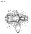
- Fig. 5 is a sectional plan view of an auxiliary transaxle according to a second embodiment of the present invention.
- Fig. 6 is a sectional plan view of an auxiliary transaxle according to a third embodiment of the present invention.
- Fig. 7 is an enlarged fragmentary sectional plan view of the auxiliary transaxle according to the third embodiment.
- Fig. 8 is a sectional plan view of an auxiliary transaxle according to a fourth embodiment of the present invention.
- Fig. 9 is a sectional plan view of an auxiliary transaxle according to a fifth embodiment of the present invention.
- Fig. 10 is a sectional plan view of an auxiliary transaxle according to a sixth embodiment of the present invention.
- Fig. 11 is a flow chart of controlling the auxiliary transaxle according to the sixth embodiment.
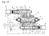
- Fig. 12 is a developed sectional plan view of an auxiliary transaxle according to a seventh embodiment of the present invention.
- Referring to Figs. 1 and 2, description will be given of a four-wheel drive utility vehicle having a pair of left and right main (rear)
drive wheels 5 and a pair of auxiliary (front)drive wheels 8, serving as an example of multi-wheel drive vehicle according to the present invention. Alternatively, the vehicle may be provided with an additional pair of main drive wheels (such as middle drive wheels) so as to be made into a six-wheel drive vehicle. - The vehicle has a vehicle body including a front frame 1a and a
rear frame 1b integrally connected to each other.Rear frame 1b includes a footboard, which is substantially rectangular in plan view, is spread overrear frame 1b, and vertical side plates erected from front, rear, left and right side ends of the footboard. Acargo deck 1c is supported aboverear frame 1b. - An
engine 3 having a lateral crankshaft is disposed inrear frame 1b. In this embodiment,engine 3 has a leftwardly projectingoutput shaft 3a. A main transaxle T1 is disposed behindengine 3. Main transaxle T1 has aninput shaft 21 projecting leftward in parallel tooutput shaft 3a ofengine 3. Abelt type transmission 4, which may be a CVT (continuously variable transmission), is drivingly interposed betweenoutput shaft 3a andinput shaft 21. - Main transaxle T1 supports left and
right axles main drive wheels 5 are disposed on lateral outside of the left and right side plates ofrear frame 1b.Bearing members 6 are attached onto outer surfaces of the left and right side plates ofrear frame 1b. Eachmain drive wheel 5 has awheel axis shaft 5a penetrating each of bearingmembers 6 so as to be disposed coaxially to each ofaxles coupling 7 is spline-fitted onto an inner end ofwheel axis shaft 5a and an outer end of each ofaxles rear frame 1b so as to integrally rotatably connect eachwheel axis shaft 5a to each ofaxles brake 5b is disposed in a rim of each ofmain drive wheels 5. - A front portion of front frame 1a is higher than a rear portion of front frame 1a. An auxiliary transaxle T2 is disposed at a substantially lateral middle position below the front portion of front frame 1a. Auxiliary transaxle T2 supports left and
right axles auxiliary drive wheels 8 are steerably disposed on lateral outside of the front portion of front frame 1a coaxially to each ofaxles axles universal joints 9a and apropeller shaft 9b. The front portion of front frame 1a is covered with afront cover 10 having a rear upper portion serving as an instrument panel, above which asteering wheel 11 is disposed. A typical suspension device, such as a coiled spring or a shock absorber, is interposed between each of left and right side ends of front frame 1a and each ofauxiliary drive wheels 8 so thatauxiliary drive wheels 8 are suspended from front frame 1a independently of each other. - An interior structure of main transaxle T1 will be described with reference to Figs. 1 and 2. Main transaxle T1 includes a
housing 20 whose bottom portion is fastened to the footboard ofrear frame 1b by bolts so as to be fixedly disposed substantially upright adjacent toengine 3 in the vehicle. In this regard, inhousing 20,input shaft 21,coaxial axles counter shaft 22 are disposed laterally in parallel so thatcounter shaft 22 is disposed aboveaxles input shaft 21. - A reversing
gear mechanism 23 is interposed betweeninput shaft 21 andcounter shaft 22 inhousing 20 so as to decide one of opposite rotary directions ofcounter shaft 22. The rotary force ofcounter shaft 22 is transmitted to a final gear of adifferential gear unit 25 differentially connectingaxles Differential gear unit 25 is provided with a typicaldifferential locking mechanism 26. - Main transaxle T1 takes off power from
counter shaft 22 on the laterally opposite side tobelt type transmission 4 so as to transmit the power to auxiliary transaxle T2. In other words, the output force ofcounter shaft 22 is distributed betweendifferential gear unit 25 for drivingaxles axles - In this regard, a
PTO casing 27 is attached onto the right side surface of housing 20 (laterally opposite to belt type transmission 4) so as to contain an utmost end ofcounter shaft 22 projecting outward fromhousing 20. InPTO casing 27, aninput bevel gear 28 is fixed on the utmost end ofcounter shaft 22, anoutput shaft 30 is journalled in perpendicular to countershaft 22, and anoutput bevel gear 29 is fixed onoutput shaft 30 so as to mesh withinput bevel gear 28.Output shaft 30 projects outward from PTO casing 27 toward auxiliary transaxle T2. - An interior structure of auxiliary transaxle T2 according to a first embodiment will be described with reference to Fig. 3. Auxiliary transaxle T2 includes a
housing 40 supporting left andright axles input shaft 42.Axles housing 40.Input shaft 42 is disposed in perpendicular toaxles housing 40 to be drivingly connected tooutput shaft 30 via apropeller shaft 100 anduniversal joints 101 so as to receive the rotary force from main transaxle T1 synchronized to the rotation ofmain drive wheels 5. - In
housing 40, abevel pinion 43 is formed on an (front) end ofinput shaft 42, and meshes with abevel center gear 44 coaxially and relatively rotatably fitted aroundaxles - A gear ratio of
center gear 44 to bevelpinion 43 is set so that, while clutches CL and CR are engaged, total peripheral speeds ofmain drive wheels 5 become 110 - 120 percent of total peripheral speeds ofauxiliary drive wheels 8. Therefore, both clutches CL and CR (especially, one forauxiliary drive wheel 8 on the inside of the turning vehicle) are prevented from being unexpectedly engaged during either straight travel or turning of the vehicle in a two-wheel drive mode by driving only unslippingmain drive wheels 5. -
Housing 40 is dividable into four housing elements, i.e., afirst housing element 40a, asecond housing element 40b, athird housing element 40c and afourth housing element 40d. Threehousing elements axles Fourth housing element 40d is joined to a rear surface offirst housing element 40a so as to be separable fromfirst housing element 40a in perpendicular toaxles First housing element 40a serves as one of left and right side walls (in this embodiment, a right side wall) ofhousing 40, andthird housing element 40c serves as the other right or left side wall (in this embodiment, a left side wall) ofhousing 40. - A
bearing 48 is supported between first andfourth housing elements bearing 49 is supported infourth housing element 40d, so thatinput shaft 42 is journalled bybearings fourth housing elements Center gear 44 is journalled at one end thereof byfirst housing element 40a via abearing 50, and at the other end thereof bysecond housing element 40b via abearing 51, so as to mesh withbevel pinion 43 infirst housing element 40a. -
Center gear 44 includes afirst support element 45, asecond support element 46 and a rig gear element 47.Bearing 50 is disposed onfirst support element 45, and bearing 51 is disposed onsecond support element 46.First support element 45 has a stepped portion, to which ring gear element 47 is fitted.Elements axles common bolts 99 so as to constitutecenter gear 44. -
First support element 45 is integrally formed with acylindrical shaft 45a extended throughsecond support element 46 towardthird housing element 40c. Proximal end portions ofaxles cylindrical shaft 45a offirst support element 45 so as to face each other. Clutch CL is interposed betweencylindrical shaft 45a andaxle 41L, and clutch CR is interposed betweencylindrical shaft 45a andaxle 41R. -
Axle 41L is formed with a plurality ofrecesses 52L aligned on the outer periphery thereof facing the inner peripheral surface ofcylindrical shaft 45a, andaxle 41R is formed with a plurality ofrecesses 52R aligned on the periphery thereof facing the inner peripheral surface ofcylindrical shaft 45a.Cylindrical shaft 45a is formed with penetratingradial holes 53L corresponding torespective recesses 52L, and with penetratingradial holes 53R corresponding torespective recesses 52R. Aball 54L is disposed between eachrecess 52L andcorresponding hole 53L so as to be movable in the radial direction ofaxle 41L. Aball 54R is disposed between eachrecess 52R andcorresponding hole 53R so as to be movable in the radial direction ofaxle 41R. - A
clutch slider 55 is axially movably disposed between an inner peripheral surface ofsecond support element 46 and an outer peripheral surface ofcylindrical shaft 45a.Clutch slider 55 is selectively shifted between a clutch-on position and a clutch-off position.Pressure members clutch slider 55 so as to axially slidably fitted on the outer peripheral surface ofcylindrical shaft 45a.Springs clutch slider 50 andrespective pressure members respective pressure members respective balls - In Fig. 3,
clutch slider 55 is illustrated so that a portion thereof aboveaxles axles clutch slider 55 is disposed at the clutch-on position,pressure members respective balls respective recesses holes center gear 44 toaxles clutch slider 55 is disposed at the clutch-off position, due to shapes ofpressure members cylindrical shaft 45a ofcenter gear 44,balls respective holes respective recesses axles center gear 44. - On one end portion of
clutch slider 55 towardthird housing element 40c is formed acam 58 shaped to alternately align substantially triangular convexes and concaves along the periphery thereof. Aspring 59 is interposed between the other end portion ofclutch slider 55 andfirst housing element 40a so as to constantly biasclutch slider 55 to thethird housing element 40c side. The outer peripheral surface ofclutch slider 55 is spline-fitted to the inner peripheral surface ofsecond support element 45 so thatclutch slider 55 is rotatable integrally withcenter gear 44 and axially slidable relative to centergear 44. -
Axle 41L is disposed inthird housing element 40c so as to be journalled by abearing 60 via a two-way clutch BC. Two-way clutch BC comprises aninner ring 61,cylindrical rollers 62, acage 63, anouter ring 64, and aspring 66. -
Inner ring 61,cage 63 andouter ring 64 are concentrated centered on the axis ofaxle 41L.Inner ring 61 is freely rotatably provided onaxle 41L.Outer ring 64 is rotatably held by bearing 60.Cage 63 is formed with roller-holding portions betweeninner ring 61 andouter ring 64 so as to holdrespective rollers 62 betweeninner ring 61 andouter ring 64.Cage 63 is also formed with a verticalside plate portion 63a facing a (left) side wall portion ofthird housing element 40c. The roller-holding portions ofcage 63 are extended from the space betweeninner ring 61 andouter ring 64, and connected to an outer peripheral edge ofside plate portion 63a. A wavedwasher 67 and a thrust bearing are interposed between an inside surface ofside plate portion 63a andinner ring 61 aroundaxle 41L. Afriction plate 63b is fitted onto an outside surface ofside plate portion 63a (opposite to the inside surface thereof), and pressed against a retainingplate 68 held by the side wall ofthird housing element 40c so as to applying a certain braking force tocage 63. - Action of two-way clutch BC will be described with reference to Figs. 4(a), 4(b) and 4(c). In the axial view of two-way clutch BC, the outer peripheral surface of
inner ring 61 is strictly circular, andouter ring 64 is shaped to have cam portions and roller-receptacle portions 64a for receivingrespective rollers 62 alternately aligned on the inner periphery thereof. Each of the cam portions has twocam surfaces 64b, which are symmetric in the peripheral direction ofaxle 41L. In other words, each roller-receptacle portion 64a has symmetric cam surfaces 64b at opposite ends thereof in the peripheral direction ofaxle 41L. - Fig. 4(a) illustrates a state of two-way clutch BC when the vehicle is stationary.
Rollers 62 pressed byspring 66 are disposed at the deepest positions of respective roller-receptacle portions 64a. - Fig. 4(b) illustrates a state of two-way clutch BC when the vehicle travels forward.
Cage 63 receives the above-mentioned braking force. Inner andouter rings roller 62 comes to abut against one of cam surfaces 64b at the opposite ends of each roller-receptacle portion 64a. Due to the above-mentioned gear ratio setting of mutually meshingbevel pinion 43 andcenter gear 44, or due to another matter, rotary speed ofinner ring 61 becomes 110 -120 percent of rotary speed ofouter ring 64 constantly, i.e., during straight travel of the unslipping vehicle. Therefore, eachroller 62 abutting againstcam surface 64b is prevented from being wedged betweencam surface 64b andinner ring 61. However, if the vehicle is slowed down by slipping ofmain drive wheel 5 so as to reduce the peripheral speed ofauxiliary drive wheels 8, the rotary speed ofouter ring 64 becomes larger than that ofinner ring 61 so that eachroller 62 abutting againstcam surface 64b is wedged betweencam surface 64b andinner ring 61, thereby engaginginner ring 61 withouter ring 64. - Fig. 4(c) illustrates a state of two-way clutch BC when the vehicle travels backward. The only different thing is that the rotational direction of inner and
outer rings ring 62 abuts against the other of cam surfaces 64b at the opposite ends of each roller-receptacle portion 64a. Description of two-way clutch BC in this state is omitted because it acts in the same way as that in the state of Fig. 4(b). -
Outer ring 64 of two-way clutch BC is integrally formed with acam 65 extended towardclutch slider 55 so as to be adapted to engage withcam 58 ofclutch slider 55, thereby constituting a shift mechanism S for shifting clutches CL and CR. If the rotary speed ofouter ring 64 exceeds the rotary speed ofinner ring 61 so as to engageinner ring 61 withouter ring 64,outer ring 64 receiving load onaxle 41L throughrollers 62 comes to rotate relative toclutch slider 55 driven together withcenter gear 44, thereby generating a thrust betweencams - Consequently, due to the thrust between
cams clutch slider 55 disposed at the clutch-off position (as the lower portion ofclutch slider 55 belowaxles clutch slider 55 aboveaxles center gear 44 toaxles main drive wheel 5 slips,auxiliary drive wheels 8 are driven so as to prevent the traveling vehicle from unexpectedly stopping. Further, even ifaxles main drive wheel 5 escapes from slipping, clutches CL and CR are quickly disengaged by the relatively light operational force ofspring 59. - Additionally, a problem of auxiliary transaxle T2 is that, if
auxiliary drive wheel 8 attached onaxle 41L fitted toinner ring 61 floats above the ground during the slipping ofmain drive wheel 5, the thrust is not generated betweencams cam 58 ofclutch slider 55 transmits a rotary force tocam 65 ofouter ring 64. To solve the problem, a spring-load type slip clutch SC is interposed betweenaxles axles axles other axle axles other axle axles -
Axle 41L is axially divided into two parts between which a torque limiter TL is interposed. The two divisional parts are integrally rotatably joined to each other through acoupling 69. Torque limiter TL has alternately aligned friction discs engaged toaxle 41L and friction discs engaged toinner ring 61 of two-way clutch BC. Adisc spring 70 presses the friction discs against one another so as to reduce the drive torque ofaxle 41L to a certain degree before transmitting the torque toinner ring 61. Torque limiter TL prevents a high load from being applied ontorollers 62, thereby preventingrollers 62 from being wedged betweeninner ring 61 and respective cam surfaces 64b. - In Fig. 3, clutches CL and CR, two-way clutch BC, shift mechanism S and torque limiter TL are disposed on one of left and right sides of
center gear 44 laterally eccentrically in auxiliary transaxle T2. If they have to be arranged in a well-balanced and compact layout, they may be alternatively disposed according to following other embodiment. - Referring to a second embodiment of auxiliary transaxle T2 shown in Fig. 5, description will be given of only points distinguished from the above first embodiment shown in Figs. 3 and 4(a) - 4(c). Description of members or portions, which are identical or similar to those in the first embodiment and are designated by the same reference numerals, is omitted unless any of them is to be specially mentioned.
- In this auxiliary transaxle T2, ball-type clutches CL and CR and
clutch slider 55 are disposed on one side ofcenter gear 44. Two-way clutch BC and torque limiter TL are disposed on the other side ofcenter gear 44. Shift mechanism S is disposed incenter gear 44. - More specifically, a
housing element 40e is attached tofirst housing element 40a so as to serve as a side wall enclosing a portion ofaxle 41R extended outward from bearing 50 journalingfirst support member 45 ofcenter gear 44. Two-way clutch BC and torque limiter TL are disposed onaxle 41R inhousing element 40e. -
Bearing 60 holdingouter ring 64 of two-way clutch BC is disposed inhousing element 40e, andcam 65 extended fromouter ring 64 is inserted intofirst support element 45. Acover 71 is attached to an end ofthird support element 46 ofcenter gear 44, and holdsspring 59 pressed against one end ofclutch slider 55 so as to biasclutch slider 55 to the clutch-on position.Cam 58 adapted to engaged withcam 65 is a member separated fromclutch slider 55, and joined to the other end ofclutch slider 55 via pins 72. - In Fig. 5, an upper portion of
clutch slider 55 aboveaxles cams clutch slider 55 belowaxles cams - Referring to a third embodiment of auxiliary transaxle T2 shown in Figs. 6 and 7, description will be given of only points distinguished from the above first embodiment shown in Figs. 3, 4(a), 4(b) and 4(c). Description of members or portions, which are identical or similar to those in the first embodiment and are designated by the same reference numerals, is omitted unless any of them is to be specially mentioned.
- The important point of the third embodiment distinguished from the first and second embodiments is that shift mechanism S for engaging and disengaging clutches CL and CR partly includes electric means while shift mechanisms S of the first and second embodiments are entirely mechanical. That is, shift mechanism S shown in Fig. 6 includes an electric switch SW for detecting existence of slipping
main drive wheel 5 and an electronic actuator Ea for axially movingpressure members -
Axles center gear 44 so as to face each other at proximal ends thereof.Transmission members axles respective recesses Center gear 44 is integrally formed at an inner peripheral portion thereof withcylindrical shaft 45a extended in opposite axial directions from the space between the proximal ends ofaxles cylindrical shaft 45a aroundaxle 41L coverstransmission member 80L, and the other portion ofcylindrical shaft 45a aroundaxle 41R coverstransmission member 80R.Cylindrical shaft 45a is formed with radial penetratingholes 53L corresponding torecesses 52L, and with radial penetratingholes 53R corresponding torecesses 52R. Each ofballs 54L is disposed betweenrecess 52L andcorresponding hole 53L, and each ofballs 54R is disposed betweenrecess 52R andcorresponding hole 53R. -
Pressure members cylindrical shaft 45a so as to be selectively set into a clutch-on state for pressingrespective balls respective recesses respective holes respective balls respective recesses - A
shift fork 81L is connected to pressuremember 56L viaspring 57L, and ashift fork 81R is connected to pressuremember 56R viaspring 57R. Afork shaft 82 penetrates bothboss portions 81a ofshift forks shift forks boss portions 81a is formed with acam slot 81b slanted from the axial direction offork shaft 82.Fork shaft 82 is rotatably but not axially slidably supported byhousing 40. A pair ofpins 82a are engaged intorespective cam slots 81b so as to project radially outward from the outer peripheral surface ofrespective boss portions 81a. - By rotating
fork shaft 82, pins 82a move inrespective cam slots 81b so as to move positions ofshift forks fork shaft 82. In Fig. 6, upper portions ofshift forks axles shift forks axles - A
clutch operation arm 83 is fixed on an outer end offork shaft 82 outsidehousing 40. A movable portion of push-and-pull type electronic actuator Ea is connected to a free tip end ofclutch operation arm 83. When a controller (not shown) receives a signal indicating the switching-on of switch SW, the controller extends or contracts the movable portion of actuator Ea so as to rotatefork shaft 82 to a certain degree, thereby generating a thrust between eachpin 82a and eachcam slot 81b. Accordingly,shift forks axles axles pressure members springs balls recesses -
Housing 40 of this embodiment includes amain housing element 40f and acover element 40g joined tomain housing element 40f so as to cover a sideward opening ofmain housing element 40f.Cylindrical shaft 45a is journalled at one end portion thereof bymain housing element 40f via a bearing, and at the other end portion thereof byside cover element 40g via a bearing.Cover element 40g is integrally formed with an expanded portion 40ga for journalingaxle 41R. The end ofcylindrical shaft 45a and a diametrically narrowedboss portion 80a oftransmission member 80R are extended into expanded portion 40ga. - A structure in expanded portion 40ga of
cover 40g will be detailed with reference to Fig. 7. Two-way clutch BC is disposed in expanded portion 40ga. In this regard,inner ring 61 is relatively rotatably disposed onboss portion 80a, however, connected toboss portion 80a via torque limiter TL. A thrust bearing and wavedwasher 67 are fitted onboss portion 80a adjacent to torque limiter TL so as to apply a certain braking force ontocage 63. - A
holder 84 is fitted onto the outer peripheral surface ofouter ring 64. Aswitch operation member 85 is spline-fitted onto the outer peripheral surface ofholder 84 so as to be not relatively rotatable but axially slidable onholder 84. A sensing portion of switch SW is screwed intocover element 40g so as to face an axially distal end surface ofswitch operation member 85. On a proximal end portion ofswitch operation member 85 towardcylindrical shaft 45a is formed acam 85a shaped to alternately align substantially triangular convexes and concaves along the periphery thereof.Cam 85a is adapted to engage with acam 45b formed on the end ofcylinder portion 45 disposed in expanded portion 40ga. Aspring 86 is interposed betweenholder 84 andswitch operation member 85 so as to biascam 85a to deeply engage withcam 45b. - This two-way clutch BC functions in the same way as illustrated in Figs. 4(a) to 4(c). In the state that torque limiter TL reduces torque of
axle 41R to be transmitted toinner ring 61, two-way clutch BC is engaged when the rotary speed ofouter ring 64 exceeds the rotary speed ofinner ring 61 due to slip ofmain drive wheel 5. At this time, a thrust is generated betweencams switch operation member 85 push the sensing portion of switch SW, thereby actuating electronic actuator Ea for engaging clutches CL and CR as mentioned above. - Clutches CL and CR in this embodiment are operated by
respective shift forks clutch slider 55. Auxiliary transaxle T2 according to a fourth embodiment shown in Fig. 8 serves as auxiliary transaxle T2 of the third embodiment modified to have a pair of two-way clutches BCL and BCR by usingshift forks - Referring to the fourth embodiment of auxiliary transaxle T2 shown in Fig. 8, description will be given of only points distinguished from the third embodiment shown in Figs. 6 and 7. Description of members or portions, which are identical or similar to those in the third embodiment and are designated by the same reference numerals, is omitted unless any of them is to be specially mentioned.
- A pair of
fork shafts housing 40.Shift forks respective fork shafts pins 82a intocam slots 81b.Clutch operation arms respective fork shafts housing 40. Movable portions of push-and-pull type electronic actuators EaL and EaR are connected to tip ends of respectiveclutch operation arms -
Transmission members respective axles outer ring 64.Switch operation members switch operation members cylindrical shaft 45a is formed with cams at axially opposite ends thereof so as to engage the respective cams formed at the proximal ends ofswitch operation members housing 40 so as to have sensing portions facing axially distal ends ofswitch operation members housing 40, respectively. - Auxiliary transaxle T2 of this embodiment is advantageous in that, even when one of left and right
auxiliary drive wheels 8 floats on the ground, the otherauxiliary drive wheel 8 gripping the ground is effectively slowed down by slipping ofmain drive wheel 5 so as to engage corresponding two-way clutch BCL or BCR. Therefore, auxiliary transaxle T2 of the fourth embodiment requires no slip clutch SC for mutually connectingaxles auxiliary drive wheels 8 without frictional resistance therebetween during turning of the vehicle. - Referring to a fifth embodiment of auxiliary transaxle T2 shown in Fig. 9, description will be given of only points distinguished from the third embodiment shown in Figs. 6 and 7. Description of members or portions, which are identical or similar to those in the third embodiment and are designated by the same reference numerals, is omitted unless any of them is to be specially mentioned.
-
Housing 40 includes upper and lower shell-like shaped housing elements 40' separably joined to each other through a horizontal plane including axes of left andright axles input shaft 42.Bearings respective axles housing 40.Bearings input shaft 42, andbearings cylindrical shaft 45a are also sandwiched between upper and lower housing members 40'. In this regard, each housing element 40' is formed with semicircular recesses into which half portions ofbearings - In this way, auxiliary transaxle T2 of the fifth embodiment has such a simple housing structure, which is advantageous in facility of assembly and reduction of costs. Auxiliary transaxle T2 according to any of the first to fourth embodiments and a later-discussed sixth embodiment may alternatively employ this simple housing structure.
-
Housing 40 is formed therein with a partitionwall holding bearing 50a, which partitions an inner space ofhousing 40 into a first chamber and a second chamber.Gears main drive wheel 5, including two-way clutch BC, is disposed in the second chamber. Lube inhousing 40 can flow between the first and second chambers. - Proximal portions of
axles cylinder shaft 45a so as to face each other. Proximal portions ofaxles cylinder shaft 45a are diametrically expanded so as to serve asrespective transmission members cylindrical shaft 45a and each oftransmission members - One end of
cylindrical shaft 45a, formed withcam 45b, is extended distally from bearing 50a into the second chamber so as to engage withcam 85a fixed to one end surface ofswitch operation member 85. In the second chamber, two-way clutch BC is constructed so thatinner ring 61 is fitted onaxle 41L, andswitch operation member 85 is spline-fitted on the outer peripheral surface ofouter ring 64 so as to be not relatively rotatable but axially slidable onouter ring 64.Disc spring 86 is interposed betweenouter ring 64 andcam 85a so as to biasswitch operation member 85 to a switch-off position. The other end ofcylindrical shaft 85 faces the sensing portion of electric switch SW screwed into a side wall of the second chamber. - Vertical retaining
plate 68 is disposed adjacent to the side wall of the second chamber. An opened cylindrical portion is extended from an outer peripheral edge of retainingplate 68 along the outer peripheral surface ofouter ring 64 so as to guideouter ring 64. The cylindrical portion of retainingplate 68 is radially stepped at an axial intermediate position so as to not relatively rotatably fit to an inside surface of the side wall of the second chamber. -
Axle 41L is extended outward through retainingplate 68. A retaining ring is fixed onaxle 41L adjacent to a vertical outside surface of retainingplate 68, and a thrust bearing is interposed onaxle 41L between the retaining ring and the vertical outside surface of retainingplate 68. - A vertical
side plate portion 63a ofcage 63 is disposed in the cylindrical portion of retainingplate 68 adjacent to a vertical inside surface of retainingplate 68. Afriction plate 63b is stuck to an outside surface of verticalside plate portion 63a facing to the vertical inside surface of retainingplate 68.Axle 41L penetrates the verticalside plate portion 63a andfriction plate 63b. A retaining ring is fixed onaxle 41L opposite to vertical retainingplate 68 with respect to verticalside plate portion 63a ofcage 63. A thrust bearing and wavedwasher 67 are fitted onaxle 41L between the retaining ring and verticalside plate portion 63a so as to pressfriction plate 63b against the vertical inside surface of retainingplate 68, thereby applying a certain braking force ontocage 63. - Torque limiter TL is interposed between
inner ring 61 andaxle 41L so as to reduce torque ofaxle 41L to be transmitted toinner ring 61. Torque limiter TL comprises alternately aligned friction plates fitted toinner ring 61 and friction plates fitted toaxle 41L. Torque limiter TL further comprises a disc spring pressing the friction plates against one another by a certain biasing force. - Spring-load type slip clutch SC is interposed between
axles axles axle 41L and friction plates fitted toaxle 41R. Slip clutch SC further comprises a disc spring pressing the friction plates against one another by a certain biasing force. - Push-and-pull type electronic actuator Ea has a
casing 88a screwed into a side wall ofhousing 40. Actuator Ea has anelectric motor 88b attached onto a distal end ofcasing 88a outsidehousing 40. Aaccelerator 88c, which may include a planetary gear mechanism, is attached toelectric motor 88b so as to accelerate output rotation ofmotor 88b, and a threadedshaft 88d serving as an output shaft ofaccelerator 88c is extended coaxially to forkshaft 82 and towardfork shaft 82. Anut 88e is screwed on threadedshaft 88d, and not relatively rotatably and not axially slidably engages to apiston 88f coaxially abutting against a distal end offork shaft 82. - The output rotation of
electric motor 88b is controlled by a controller (not shown), and accelerated byaccelerator 88c so as to rotate threadedshaft 88d at high speed. By rotating threadedshaft 88d,nut 88e andpiston 88f are axially moved alongthread shaft 88d so as to axially movefork shaft 82 abutting againstpiston 88f.Piston 88f andfork shaft 82 illustrated in Fig. 9 are disposed at the farthest axial position fromelectric motor 88b. - In
housing 40,shift fork 81L engaging withpressure member 56L of clutch CL and shiftfork 81R engaging withpressure member 56R of clutch CR are axially slidably fitted onfork shaft 82 so as to be aligned left and right. Retainingrings fork shaft 82, so that retainingring 89a is nearest to actuator Ea, and retainingring 89c is farthest from actuator Ea.Shift fork 81L andspring 57L are disposed onfork shaft 82 between retainingrings Shift fork 81R andspring 57R are disposed onfork shaft 82 between retainingrings shift forks respective springs -
Shift forks compressed spring 59 wound onfork shaft 82 between retainingring 89c and a side wall ofhousing 40 opposite to actuator Ea. Whenfork shaft 82 is free from the thrust force ofpiston 88f,spring 59 expands to push retainingring 89c so as to pushfork shaft 82 together withshift forks shift forks fork shaft 82 in contact withpiston 88f. - Auxiliary transaxle T2 of the fifth embodiment functions as follows: the rotation of
center gear 44 receiving power taken off from main transaxle T1 for drivingmain drive wheels 5 is transmitted toouter ring 64 of two-way clutch BC viacylinder shaft 45a,cams switch operation member 85. On the contrary, the rotation ofauxiliary drive wheels 8 is transmitted toinner ring 61 of two-way clutch BC. - Two-way clutch BC functions in the same way as shown in Figs. 4(a) to 4(c). In this regard, if the vehicle traveling in a two-wheel drive mode by driving only main drive wheels 5 (without driving of auxiliary drive wheels 8) has
main drive wheel 5 slip, a thrust is generated betweencams switch operation member 85 to switch on electric switch SW. Therefore,motor 88b is driven to move fork shaft 82 (rightward in Fig. 9) againstspring 59 so as to simultaneously moveshift forks pressure members springs auxiliary drive wheels 8 automatically start to be driven, i.e., the vehicle comes to travel in a four-wheel drive mode. - If
main drive wheel 5 having slipped escapes from slipping, the thrust caused betweencams switch operation member 85 is canceled so thatswitch operation member 85 is returned by the biasing force ofspring 86 so as to switch off electric switch SW. Therefore,motor 88b is stopped, and forkshaft 82 moves (leftward in Fig. 9) by the force ofspring 59 until retainingring 89a abuts against an inside surface of the side wall ofhousing 40. Simultaneously,spring 59pushes retaining ring 89c to moveshift forks pressure members auxiliary drive wheels 8 is automatically canceled so that the vehicle comes to travel in the two-wheel drive mode. - Referring to a sixth embodiment of auxiliary transaxle T2 shown in Fig. 10, description will be given of only points distinguished from the fifth embodiment shown in Fig. 9. Description of members or portions, which are identical or similar to those in the fifth embodiment and are designated by the same reference numerals, is omitted unless any of them is to be specially mentioned.
- Each of the third embodiment of auxiliary transaxle T2 shown in Fig. 6 and the fifth embodiment of auxiliary transaxle T2 shown in Fig. 9 comprises shift mechanism S including electronic actuator Ea, and electronic actuator Ea is controlled by use of means for detecting existence of slipping of main drive wheel 5 (judging means for judging whether or not
main drive wheel 5 slips), including two-way clutch BC,switch operation member 85 with the cam, and electric switch SW. On the other hand, in the present embodiment of auxiliary transaxle T2 shown in Fig. 10, the means for detecting existence of slipping ofmain drive wheel 5, which is used for controlling actuator Ea of shift mechanism S, comprises shift mechanism S including agear speed sensor 91 for detecting the speed of rotation transmitted from main transaxle T1, anaxle speed sensor 93 for the speed of rotation transmitted fromauxiliary drive wheels 8, and a controller C. Controller C compares the detection values fromsensors main drive wheel 5 slips. Further, auxiliary transaxle T2 shown in Fig. 10 is provided with asensitivity adjusting dial 94 for adjusting a threshold value for judging whether or notmain drive wheel 5 slips. - Since auxiliary transaxle T2 of the present embodiment includes no two-way clutch, an end portion of
cylindrical shaft 45a supportingcenter gear 44 does not have to be provided for sensing engaging or disengaging of the two-way clutch, thereby reducing a space inhousing 40 for the sensor for detecting the condition of the two-way clutch. Consequently, auxiliary transaxle T2 can be compacted. -
Axle speed sensor 91 is an electromagnetic rotary speed sensor for picking up rotary speed of center gear 44 (Nin) is screwed into a side wall of housing (cover)element 40g. Arotary plate 90 is stuck to a back surface ofcenter gear 44.Rotary plate 90 is formed with acircular portion 90a having convexes and concaves alternately aligned in a circle on the surface thereof at regular intervals. A sensing portion ofrotary sensor 91 faces a part ofcircular portion 90a. -
Axle speed sensor 93 is an electromagnetic rotary speed sensor for picking up rotary speed ofaxle 41L (Nout) is screwed into a side wall of housing (cover)element 40g.Axle 41L is formed on the outer peripheral surface thereof with asplined portion 92 having convexes and concaves alternately aligned therealong at regular intervals. A sensing portion ofrotary sensor 93 faces a part ofsplined portion 92. -
Gear speed sensor 91 may be replaced with a speedometer of the vehicle, or with a rotary speed sensor for detecting rotary speed of an axle ofmain drive wheel 5, which is made similarly toaxle speed sensor 93 for detecting rotary speed ofaxle 41L. However, auxiliary transaxle T2 shown in Fig. 10 integrally provided with bothrotary speed sensors - A gear ratio of
center gear 44 to bevelpinion 43 in auxiliary transaxle T2 is set to be larger than a gear ratio of the final gear ofdifferential gear unit 25 to countershaft 22 andaxles axle 41L exceeds rotary speed Nin ofcenter gear 44 on the input side of auxiliary transaxle T2 even if steerableauxiliary drive wheel 8 drivingly connected toaxle 41L is disposed on the inside of the vehicle and slowed down during turning of the vehicle. - Control of electronic actuator Ea by controller C will be detailed with reference to a flow chart of Fig. 11. Detection signals about from respective
rotary speed sensors center gear 44 synchronized to rotary ofmain drive wheel 5 and rotary speed Nout ofaxle 41L, i.e., of left auxiliary drive wheel 8 (at astep 1 of the flow chart). Controller C calculates a rotary speed ratio Nin / Nout, i.e., a ratio of rotary speed Nin to rotary speed Nout (at astep 2 of the flow chart). Controller C compares the calculated ratio with a threshold t (at astep 3 of the flow chart) so as to judge whether or notmain drive wheel 5 slips. For instance, threshold t for thestep 3 is set to be 0.8, as shown in Fig. 11. - If the calculated rotary speed ratio (Nin / Nout) exceeds or is equal to threshold t during two-wheel drive traveling of the vehicle by driving only
main drive wheels 5, controller C judges thatmain drive wheels 5 do not slip. Then, controller C does not output a signal for actuating electronic actuator Ea (at astep 4 of the flow chart). - If the calculated rotary speed ratio (Nin / Nout) is less than threshold t, controller C judges that any of
main drive wheels 5 slips. Then, controller C outputs a signal for actuating electronic actuator Ea so as to driveauxiliary drive wheels 8 simultaneously to driving ofmain drive wheels 5, thereby putting the vehicle into the four-wheel drive mode (at astep 5 of the flow chart). - Afterward, the detection of rotary speeds Nin and Nout (at a
step 6 of the flow chart), the calculation of the rotary speed ratio (Nin / Nout) (at astep 7 of the flow chart) and the comparison of the calculated rotary speed ratio (Nin / Nout) with threshold t (at astep 8 of the flow chart) are repeated. While a renewed rotary speed ratio (Nin / Nout) is less than the threshold value, controller C maintains to output the signal for actuating electronic actuator Ea (at thestep 5 of the flow chart) so as to keep the vehicle in the four-wheel drive mode. If a renewed rotary speed ratio (Nin / Nout) exceeds or is equal to the threshold value during the four-wheel drive traveling of the vehicle, controller C judgesmain drive wheel 5 escapes from slipping. Then, controller C stops the output of the signal for actuating electronic actuator Ea (at astep 9 of the flow chart) so as to return the vehicle into the two-wheel drive mode. - Threshold t can be manually adjusted by rotating
dial 94 shown in Fig. 10.Dial 94 is disposed adjacent to driver'sseat 2 of the vehicle, e.g., on an instrument panel.Dial 94 can be switched among a normal position N for setting threshold t to be a standard value, a sensitive position SV for setting threshold t to be larger than the standard value, and an insensitive IS for setting threshold t to be smaller than the standard value. - The setting of
dial 94 to sensitive position SV suits for strongly traveling over a damp ground, because the vehicle can be put into the four-wheel drive mode in high sensitive response to slipping ofmain drive wheel 5. The setting ofdial 94 to insensitive position IS suits for softly traveling on a turf to be strictly prevented from being damaged, because the vehicle can travel in the two-wheel drive mode unless the degree of slipping ofmain drive wheel 5 becomes considerably large. - Alternatively, the gear ratio of
center gear 44 to bevelpinion 43 in auxiliary transaxle T2 may be set to be equal to the gear ratio of the final gear ofdifferential gear unit 25 to countershaft 22 in main transaxle T1. In this case, threshold t should be smaller than the value set in the above-mentioned case where the gear ratio ofcenter gear 44 to bevelpinion 43 in auxiliary transaxle T2 is larger than the gear ratio of the final gear ofdifferential gear unit 25 to countershaft 22 in main transaxle T1. Threshold t in this case may be 0.7, for instance. - Referring to a seventh embodiment of auxiliary transaxle T2 shown in Fig. 12, description will be given of only points distinguished from the sixth embodiment shown in Figs. 10 and 11. Description of members or portions, which are identical or similar to those in the sixth embodiment and are designated by the same reference numerals, is omitted unless any of them is to be specially mentioned. Further, in Fig. 12, mutually meshing
bevel pinion 43 andinput shaft 42, which really exist in the present auxiliary transaxle T2, are not illustrated because Fig. 12 is a developed sectional view of auxiliary transaxle T2 for illustrating both electronic actuators EaL and EaR withaxles - Similar to the fourth embodiment shown in Fig. 8, the present auxiliary transaxle T2 is provided with electronic actuators EaL and EaR for shifting respective ball-type clutches CL and CR. Means of the present auxiliary transaxle T2 for detecting the slipping of
main drive wheel 5 comprisesgear speed sensor 91 for detecting rotary speed ofcenter gear 44 to be inputted toauxiliary drive wheels 8,axle speed sensors right axles auxiliary drive wheels 8, asteering angle sensor 95, and controller C for receiving signals fromsensors main drive wheel 5 comprising two-way clutches BCL and BCR. Therefore, the present transaxle T2 can be compacted becauseaxles housing 40 have no two-way clutch thereon. - The present auxiliary transaxle T2 can shift respective clutches CL and CR individually, due to respective actuators EaL and EaR. Controller C for the present auxiliary transaxle T2 controls electronic actuators EaL and EaR for solving the slipping of
main drive wheel 5 during turning of the vehicle in the following way. - During traveling of the vehicle in two-wheel drive mode by driving only
main drive wheels 5, steeringangle sensor 95 detects a turning angle of steerable auxiliary drive wheel (wheels) 8 or a turning angle ofsteering wheel 11. Controller C calculates a theoretical rotary speed ratio R ofcenter gear 44 rotated synchronously withmain drive wheels 5 toaxles auxiliary drive wheels 8 in correspondence to the turning angle of the vehicle detected by steeringangle sensor 95, thereby providing a threshold to be compared with a later-discussed calculated rotary speed ratio. Simultaneously,axle speed sensor 93L detects rotary speed NoutL ofleft axle 41L,axle speed sensor 93R detects rotary speed NoutR ofright axle 41R, androtary speed sensor 91 detects input rotary speed Nin ofcenter gear 44 rotated to be inputted toaxles axles - Controller C compares the rotary speed ratio calculated based on
sensors sensor 95. If the rotary speed ratio calculated based onsensors sensor 95, controller C judges thatmain drive wheel 5 slips. Controller C outputs a signal for actuating one of electronic actuators EaL and EaR, so as to engage one of clutches CL and CR for drivingauxiliary drive wheel 8 disposed on the inside of the turning vehicle, thereby putting the vehicle into a three-wheel drive mode by driving oneauxiliary drive wheel 8 and twomain drive wheels 5. Consequently, the vehicle can increase traction capacity while keeping smooth steering capacity. - Afterward, the
detection using sensors sensors sensor 95, controller C judges thatmain drive wheel 5 escapes from slipping, and stops the output of signal for actuating actuator EaL or EaR having being actuated, thereby disengaging corresponding clutch CL or CR. Therefore, the vehicle returns to the two-wheel drive mode. - If the rotary speed ratio calculated based on
sensors sensor 95, controller C judges that the traction capacity of the vehicle is still insufficient. Then, controller C outputs signals for actuating both electronic actuators EaL and EaR, so as to engage clutches CL and CR for drivingauxiliary drive wheels 8 disposed on the inside and outside of the turning vehicle, thereby putting the vehicle into a four-wheel drive mode by driving twoauxiliary drive wheel 8 and twomain drive wheels 5. In this case, differential rotation ofauxiliary drive wheels 8 is temporarily canceled so as to reduce the smooth steering capacity of the vehicle, and to thereby stop the vehicle in the worst case. However, escape of the vehicle from slipping in a bad road condition is preferred to the stopping of the vehicle. - Likewise, where a rotary speed ratio is defined as a ratio of input rotary speed Nin to the average rotary speed of
axles sensors sensor 95. If the rotary speed ratio calculated based onsensors sensor 95, controller C judges thatmain drive wheel 5 slips. If the rotary speed ratio calculated based onsensors main drive wheel 5 does not slip. - Alternatively, controller C for controlling electronic actuators EaL and EaR may individually compare respective detected rotary speeds of
axles corresponding axle axles - In each of the first to seventh embodiments of auxiliary transaxle T2, clutches CL and CR may alternatively be dog clutches or friction disc clutches. However, ball-type clutches CL and CR are preferable because they can surely transmit torque, they can be easily disengaged even if they have be firmly engaged, the number of component parts are small so as to reduce costs, and for other reasons.
- As mentioned above, the utility vehicle shown in Figs. 1 and 2 is an example of vehicles which can be equipped with any of the above-mentioned auxiliary transaxles T2. The auxiliary transaxles T2 may be adapted to various multi-wheel drive vehicles having main drive wheels and auxiliary drive wheels disposed before and behind, such as a six-wheel drive vehicle or a four-wheel drive vehicle, and to various vehicle types such as vehicles for traveling on irregular ground, including an ATV (All Terrain Vehicle).
- It is further understood by those skilled in the art that the foregoing description is a preferred embodiment of the disclosed apparatus and that various changes and modifications may be made in the invention without departing from the scope thereof.
Claims (21)
- A transaxle for auxiliary drive wheels of a vehicle having a main drive wheel and left and right auxiliary drive wheels, comprising:a gear to which a rotary force for driving the main drive wheel is distributed;a pair of left and right axles drivingly connected to the respective left and right auxiliary drive wheels;a pair of clutches, wherein one of the clutches is interposed between the gear and the left axle, and the other clutch is interposed between the gear and the right axle;judging means for judging whether or not the main drive wheel slips; anda shift mechanism for engaging and disengaging the pair of clutches, wherein the shift mechanism engages the pair of clutches when the judging means judges that the main drive wheel slips, and wherein the shift mechanism disengages the pair of clutches when the judging means judges that the main drive wheel does not slip.
- The transaxle according to claim 1, wherein the judging means compares rotary speed of at least one of the axles with rotary speed of the gear, wherein the judging means judges that the main drive wheel slips when rotary speed of the gear exceeds rotary speed of the at least one of the axles, and wherein the judging means judges that the main drive wheel does not slip unless rotary speed of the main drive wheel exceeds rotary speed of the at least one of the axles.
- The transaxle according to claim 2, wherein a gear ratio for driving the gear is set so that, while the pair of clutches are engaged, peripheral speed of the main drive wheel constantly exceeds peripheral speeds of the auxiliary drive wheels.
- The transaxle according to claim 1, wherein the judging means compares rotary speed ratio of the gear to at least one of the axles with a threshold, wherein the judging means judges that the main drive wheel slips when the rotary speed ratio is lower than the threshold, and wherein the judging means judges that the main drive wheel does not slip unless the rotary speed ratio is lower than the threshold.
- The transaxle according to claim 1, wherein the judging means compares a rotary speed ratio of the gear to an average rotary speed of the axles with a threshold, wherein the judging means judges that the main drive wheel slips when the rotary speed ratio is lower than the threshold, and wherein the judging means judges that the main drive wheel does not slip unless the rotary speed ratio is lower than the threshold.
- The transaxle according to claim 1, the pair of clutches comprising:a cylindrical shaft disposed around the pair of axles so as to be rotatable integrally with the gear;respective balls radially movably disposed through the cylindrical shaft, wherein the pair of axles are formed on outer peripheral surfaces thereof with respective recesses into which the respective balls can be engaged; andrespective pressure members disposed on an outer peripheral surface of the cylindrical shaft so as to be shifted between a state of pressing the respective balls into the respective recesses through the cylindrical shaft and a state of allowing the respective balls to be removed from the respective recesses through the cylindrical shaft.
- The transaxle according to claim 1, further comprising:a housing incorporating the gear, the pair of axles, and the pair of clutches, wherein the shift mechanism comprises:a push-and-pull type actuator for shifting the pair of clutches; andan operation member engaging with the pair of clutches, wherein the push-and-pull type actuator is fixed to the housing so as to have a movable portion abutting against the operation member.
- The transaxle according to claim 1, the judging means comprising:a two-way clutch interposed between the gear and the pair of axles, wherein, when rotary speed of the gear exceeds rotary speed of at least one of the pair of axles, the two-way clutch is engaged, and the shift mechanism engages the pair of clutches by the engaging of the two-way clutch, and wherein, while rotary speed of the gear is smaller than rotary speeds of the pair of axles, the two-way clutch is disengaged, and the shift mechanism disengages the pair of clutches by the disengaging of the two-way clutch.
- The transaxle according to claim 8, wherein a gear ratio for driving the gear is set so that, while the pair of clutches are engaged, peripheral speed of the main drive wheel constantly exceeds peripheral speeds of the auxiliary drive wheels.
- The transaxle according to claim 8, further comprising:a torque limiter interposed between the two-way clutch and the pair of axles, or between the gear and the two-way clutch.
- The transaxle according to claim 8, the pair of clutches comprising:a cylindrical shaft disposed around the pair of axles so as to be rotatable integrally with the gear;respective balls radially movably disposed through the cylindrical shaft, wherein the pair of axles are formed on outer peripheral surfaces thereof with respective recesses into which the respective balls can be engaged; andrespective pressure members disposed on an outer peripheral surface of the cylindrical shaft so as to be shifted between a state of pressing the respective balls into the respective recesses through the cylindrical shaft and a state of allowing the respective balls to be removed from the respective recesses through the cylindrical shaft.
- The transaxle according to claim 8, the shift mechanism comprising:a switch sensing either engaging or disengaging of the two-way clutch; andan actuator for shifting the pair of clutches, controlled according to a state of the switch.
- The transaxle according to claim 12, further comprising:a housing incorporating the gear, the pair of axles, the pair of clutches, and the two-way clutch, wherein the actuator is a push-and-pull type actuator, and the shift mechanism further comprises:an operation member engaging with the pair of clutches, wherein the push-and-pull type actuator is fixed to the housing so as to have a movable portion abutting against the operation member.
- The transaxle according to claim 1, wherein the shift mechanism comprises an actuator for engaging and disengaging the pair of clutches, and wherein the judging means comprising: a gear speed sensor for detecting rotary speed of the gear; an axle speed sensor for detecting rotary speed of one of axles; and a controller for receiving signals from both of the sensors and for controlling the actuator.
- The transaxle according to claim 14, wherein the controller compares a rotary speed ratio of the gear to the one of the axles with a threshold, wherein the controller controls the actuator so as to engage the pair of clutches when the rotary speed ratio is lower than the threshold, and wherein the controller controls the actuator so as to disengage the pair of clutches unless the rotary speed ratio is lower than the threshold.
- The transaxle according to claim 14, the pair of clutches comprising:a cylindrical shaft disposed around the pair of axles so as to be rotatable integrally with the gear;respective balls radially movably disposed through the cylindrical shaft, wherein the pair of axles are formed on outer peripheral surfaces thereof with respective recesses into which the respective balls can be engaged; andrespective pressure members disposed on an outer peripheral surface of the cylindrical shaft so as to be shifted between a state of pressing the respective balls into the respective recesses through the cylindrical shaft and a state of allowing the respective balls to be removed from the respective recesses through the cylindrical shaft.
- The transaxle according to claim 14, further comprising:a housing incorporating the gear, the pair of axles, and the pair of clutches, wherein the shift mechanism comprises:a push-and-pull type actuator for shifting the pair of clutches; andan operation member engaging with the pair of clutches, wherein the push-and-pull type actuator is fixed to the housing so as to have a movable portion abutting against the operation member.
- The transaxle according to claim 1, wherein the shift mechanism comprises an actuator for engaging and disengaging the pair of clutches, and wherein the judging means comprising: a gear speed sensor for detecting rotary speed of the gear; first and second axle speed sensors for detecting respective rotary speeds of the axles; and a controller for receiving signals from the three sensors and for controlling the actuator.
- The transaxle according to claim 18, wherein the controller compares a rotary speed ratio of the gear to an average rotary speed of the axles with a threshold, wherein the controller controls the actuator so as to engage the pair of clutches when the rotary speed ratio is lower than the threshold, and wherein the controller controls the actuator so as to disengage the pair of clutches unless the rotary speed ratio is lower than the threshold.
- The transaxle according to claim 18, the pair of clutches comprising:a cylindrical shaft disposed around the pair of axles so as to be rotatable integrally with the gear;respective balls radially movably disposed through the cylindrical shaft, wherein the pair of axles are formed on outer peripheral surfaces thereof with respective recesses into which the respective balls can be engaged; andrespective pressure members disposed on an outer peripheral surface of the cylindrical shaft so as to be shifted between a state of pressing the respective balls into the respective recesses through the cylindrical shaft and a state of allowing the respective balls to be removed from the respective recesses through the cylindrical shaft.
- The transaxle according to claim 18, further comprising:a housing incorporating the gear, the pair of axles, and the pair of clutches, wherein the shift mechanism comprises:a push-and-pull type actuator for shifting the pair of clutches; andan operation member engaging with the pair of clutches, wherein the push-and-pull type actuator is fixed to the housing so as to have a movable portion abutting against the operation member.
Applications Claiming Priority (2)
| Application Number | Priority Date | Filing Date | Title |
|---|---|---|---|
| JP2004234968 | 2004-08-12 | ||
| JP2004277337A JP2006076548A (en) | 2004-08-12 | 2004-09-24 | Transaxle for auxiliary driving wheel of multi-wheel drive vehicle |
Publications (3)
| Publication Number | Publication Date |
|---|---|
| EP1625965A2 true EP1625965A2 (en) | 2006-02-15 |
| EP1625965A3 EP1625965A3 (en) | 2006-06-07 |
| EP1625965B1 EP1625965B1 (en) | 2008-07-16 |
Family
ID=35327664
Family Applications (1)
| Application Number | Title | Priority Date | Filing Date |
|---|---|---|---|
| EP05017482A Expired - Lifetime EP1625965B1 (en) | 2004-08-12 | 2005-08-11 | Transaxle of multi-wheel drive vehicle |
Country Status (4)
| Country | Link |
|---|---|
| US (1) | US7562753B2 (en) |
| EP (1) | EP1625965B1 (en) |
| JP (1) | JP2006076548A (en) |
| DE (1) | DE602005008143D1 (en) |
Cited By (3)
| Publication number | Priority date | Publication date | Assignee | Title |
|---|---|---|---|---|
| EP1923605A2 (en) | 2006-11-10 | 2008-05-21 | GKN Driveline Torque Technology KK | Power transmission apparatus |
| EP3027456A4 (en) * | 2013-07-31 | 2017-06-07 | The Hilliard Corporation | True four wheel drive system for vehicle |
| CN108266463A (en) * | 2017-01-04 | 2018-07-10 | 李激初 | Clutch |
Families Citing this family (16)
| Publication number | Priority date | Publication date | Assignee | Title |
|---|---|---|---|---|
| US8596398B2 (en) | 2007-05-16 | 2013-12-03 | Polaris Industries Inc. | All terrain vehicle |
| JP5065106B2 (en) * | 2008-03-12 | 2012-10-31 | Ntn株式会社 | Rotation transmission device |
| DE102008053058A1 (en) * | 2008-10-24 | 2010-04-29 | Vassili Ivanov | Driving device for e.g. four-wheeled vehicle, has sensor arranged between gear unit and chassis and another sensor arranged between reducing gear and gear unit for measuring frequency of rotary movement of chassis |
| JP2010247671A (en) | 2009-04-15 | 2010-11-04 | Kanzaki Kokyukoki Mfg Co Ltd | Power unit for multi-wheel drive vehicle |
| WO2011006245A1 (en) * | 2009-07-17 | 2011-01-20 | Diversitech Equipment And Sales (1984) Ltd. | Fume extraction system with automatic fume hood positioning |
| US8677852B2 (en) * | 2010-02-23 | 2014-03-25 | GM Global Technology Operations LLC | Multiplexed electromechanical actuator mechanism |
| JP2012171609A (en) * | 2011-02-24 | 2012-09-10 | Kanzaki Kokyukoki Manufacturing Co Ltd | Transmission with torque limiter |
| US8744710B2 (en) * | 2011-03-30 | 2014-06-03 | Nissin Kogyo Co., Ltd. | Control device for controlling drive force that operates on vehicle |
| US8574111B2 (en) | 2011-05-10 | 2013-11-05 | Deere & Company | Dual torque limiter |
| US8870702B2 (en) * | 2011-12-30 | 2014-10-28 | Kawasaki Jukogyo Kabushiki Kaisha | Power switching device for vehicles |
| US8801561B1 (en) * | 2013-02-27 | 2014-08-12 | Kawasaki Jukogyo Kabushiki Kaisha | Power switching device for vehicle |
| US9731597B2 (en) * | 2015-12-14 | 2017-08-15 | American Axle & Manufacturing, Inc. | Disconnectable driveline with brake system |
| JP6669096B2 (en) * | 2017-02-06 | 2020-03-18 | トヨタ自動車株式会社 | Differential device for four-wheel drive vehicle |
| US11767060B2 (en) * | 2019-04-12 | 2023-09-26 | Textron Innovations Inc. | Lightweight vehicle |
| KR102279624B1 (en) * | 2019-11-11 | 2021-07-20 | 국방과학연구소 | control method of pivot steering for 6 wheel drive vehicle |
| CN118665214B (en) * | 2024-07-01 | 2025-10-10 | 一汽解放汽车有限公司 | A dual electric drive axle slip torque distribution method, device, system, VCU and medium |
Citations (2)
| Publication number | Priority date | Publication date | Assignee | Title |
|---|---|---|---|---|
| JPS6127318A (en) | 1984-07-02 | 1986-02-06 | ダナ、コーパレイシヤン | Non-differential drive axle |
| JP2002059754A (en) | 2000-06-08 | 2002-02-26 | Kanzaki Kokyukoki Mfg Co Ltd | Front axle driving device for multi-wheel driving vehicle |
Family Cites Families (6)
| Publication number | Priority date | Publication date | Assignee | Title |
|---|---|---|---|---|
| US2850920A (en) * | 1950-12-21 | 1958-09-09 | Rockwell Spring & Axle Co | Vehicle drive mechanism |
| US5203232A (en) * | 1991-02-18 | 1993-04-20 | Ntn Corporation | Rotation transmitting device |
| US5540119A (en) * | 1994-09-27 | 1996-07-30 | Hudson; John L. | Cam-actuated clutch differential drive assembly |
| IT1286172B1 (en) * | 1996-07-12 | 1998-07-07 | New Holland Italia Spa | ELECTRONIC TRANSMISSION FOR A FOUR WHEEL DRIVE VEHICLE. |
| AT3257U1 (en) * | 1998-11-20 | 1999-12-27 | Steyr Daimler Puch Ag | DRIVE UNIT FOR DRIVING AN ALL-WHEELED VEHICLE WITH SPEED-DIFFERENTIAL-RELATED HYDRAULIC CLUTCH |
| US6186258B1 (en) * | 1999-02-09 | 2001-02-13 | General Motors Corporation | Dynamic all wheel drive |
-
2004
- 2004-09-24 JP JP2004277337A patent/JP2006076548A/en active Pending
-
2005
- 2005-08-11 DE DE602005008143T patent/DE602005008143D1/en not_active Expired - Lifetime
- 2005-08-11 EP EP05017482A patent/EP1625965B1/en not_active Expired - Lifetime
- 2005-08-12 US US11/202,220 patent/US7562753B2/en not_active Expired - Fee Related
Patent Citations (2)
| Publication number | Priority date | Publication date | Assignee | Title |
|---|---|---|---|---|
| JPS6127318A (en) | 1984-07-02 | 1986-02-06 | ダナ、コーパレイシヤン | Non-differential drive axle |
| JP2002059754A (en) | 2000-06-08 | 2002-02-26 | Kanzaki Kokyukoki Mfg Co Ltd | Front axle driving device for multi-wheel driving vehicle |
Cited By (6)
| Publication number | Priority date | Publication date | Assignee | Title |
|---|---|---|---|---|
| EP1923605A2 (en) | 2006-11-10 | 2008-05-21 | GKN Driveline Torque Technology KK | Power transmission apparatus |
| EP1923605A3 (en) * | 2006-11-10 | 2009-11-18 | GKN Driveline Torque Technology KK | Power transmission apparatus |
| US8667864B2 (en) | 2006-11-10 | 2014-03-11 | Gkn Driveline Torque Technology Kk | Power transmission apparatus |
| EP3027456A4 (en) * | 2013-07-31 | 2017-06-07 | The Hilliard Corporation | True four wheel drive system for vehicle |
| CN108266463A (en) * | 2017-01-04 | 2018-07-10 | 李激初 | Clutch |
| CN108266463B (en) * | 2017-01-04 | 2024-02-27 | 广东洛梵狄智能科技有限公司 | clutch mechanism |
Also Published As
| Publication number | Publication date |
|---|---|
| US20060032692A1 (en) | 2006-02-16 |
| US7562753B2 (en) | 2009-07-21 |
| DE602005008143D1 (en) | 2008-08-28 |
| JP2006076548A (en) | 2006-03-23 |
| EP1625965B1 (en) | 2008-07-16 |
| EP1625965A3 (en) | 2006-06-07 |
Similar Documents
| Publication | Publication Date | Title |
|---|---|---|
| EP1625965B1 (en) | Transaxle of multi-wheel drive vehicle | |
| US6824487B2 (en) | Transfer case for four-wheel drive vehicle | |
| US8177672B2 (en) | Driving-force transmitting apparatus for four-wheel-drive vehicle | |
| US6877573B2 (en) | Multi-wheel-driving vehicle | |
| US7922615B2 (en) | Two-speed transfer case with ballramp clutch actuator | |
| US4566554A (en) | Four wheel drive system with center differential unlock control responsive to steering angle | |
| EP0813984B1 (en) | Full-time transfer case with integrated planetary gear assembly | |
| EP0396323B1 (en) | Torque distribution control system for a four-wheel drive motor vehicle | |
| JPS59216731A (en) | Four-wheel-drive vehicle | |
| US8845474B2 (en) | Four wheel drive vehicle | |
| GB2267322A (en) | Differential gearing unit | |
| US6199653B1 (en) | Four-wheel driven vehicle | |
| CA2463463A1 (en) | Two-speed full-time transfer case with integrated planetary gearset and synchronized range shift | |
| CN107020951B (en) | Splitter | |
| JPH05221250A (en) | Limited differential gear | |
| JP5049765B2 (en) | Differential limiter | |
| JP2943324B2 (en) | Four-wheel drive vehicle | |
| JP3235598B2 (en) | Tractor | |
| JP2000142152A (en) | Four-wheel drive system for vehicles | |
| EP0274168B1 (en) | Power transmission device for a four wheel drive vehicle | |
| JP2824657B2 (en) | Control device for mobile agricultural machine | |
| JPS63251327A (en) | Differential gear lock control device for four-wheel-drive vehicle | |
| JP2024126394A (en) | Four-wheel drive vehicle | |
| JP2918916B2 (en) | Drive wheel switching control device for four-wheel drive vehicle | |
| JPH0646060B2 (en) | Car power transmission |
Legal Events
| Date | Code | Title | Description |
|---|---|---|---|
| PUAI | Public reference made under article 153(3) epc to a published international application that has entered the european phase |
Free format text: ORIGINAL CODE: 0009012 |
|
| AK | Designated contracting states |
Kind code of ref document: A2 Designated state(s): AT BE BG CH CY CZ DE DK EE ES FI FR GB GR HU IE IS IT LI LT LU LV MC NL PL PT RO SE SI SK TR |
|
| AX | Request for extension of the european patent |
Extension state: AL BA HR MK YU |
|
| PUAL | Search report despatched |
Free format text: ORIGINAL CODE: 0009013 |
|
| AK | Designated contracting states |
Kind code of ref document: A3 Designated state(s): AT BE BG CH CY CZ DE DK EE ES FI FR GB GR HU IE IS IT LI LT LU LV MC NL PL PT RO SE SI SK TR |
|
| AX | Request for extension of the european patent |
Extension state: AL BA HR MK YU |
|
| 17P | Request for examination filed |
Effective date: 20061207 |
|
| 17Q | First examination report despatched |
Effective date: 20070112 |
|
| AKX | Designation fees paid |
Designated state(s): DE FR GB IT SE |
|
| GRAP | Despatch of communication of intention to grant a patent |
Free format text: ORIGINAL CODE: EPIDOSNIGR1 |
|
| GRAS | Grant fee paid |
Free format text: ORIGINAL CODE: EPIDOSNIGR3 |
|
| GRAA | (expected) grant |
Free format text: ORIGINAL CODE: 0009210 |
|
| AK | Designated contracting states |
Kind code of ref document: B1 Designated state(s): DE FR GB IT SE |
|
| REG | Reference to a national code |
Ref country code: GB Ref legal event code: FG4D |
|
| REF | Corresponds to: |
Ref document number: 602005008143 Country of ref document: DE Date of ref document: 20080828 Kind code of ref document: P |
|
| PLBE | No opposition filed within time limit |
Free format text: ORIGINAL CODE: 0009261 |
|
| STAA | Information on the status of an ep patent application or granted ep patent |
Free format text: STATUS: NO OPPOSITION FILED WITHIN TIME LIMIT |
|
| 26N | No opposition filed |
Effective date: 20090417 |
|
| PGFP | Annual fee paid to national office [announced via postgrant information from national office to epo] |
Ref country code: DE Payment date: 20090831 Year of fee payment: 5 Ref country code: GB Payment date: 20090827 Year of fee payment: 5 |
|
| PG25 | Lapsed in a contracting state [announced via postgrant information from national office to epo] |
Ref country code: SE Free format text: LAPSE BECAUSE OF FAILURE TO SUBMIT A TRANSLATION OF THE DESCRIPTION OR TO PAY THE FEE WITHIN THE PRESCRIBED TIME-LIMIT Effective date: 20081016 |
|
| PGFP | Annual fee paid to national office [announced via postgrant information from national office to epo] |
Ref country code: IT Payment date: 20090819 Year of fee payment: 5 |
|
| GBPC | Gb: european patent ceased through non-payment of renewal fee |
Effective date: 20100811 |
|
| REG | Reference to a national code |
Ref country code: FR Ref legal event code: ST Effective date: 20110502 |
|
| PG25 | Lapsed in a contracting state [announced via postgrant information from national office to epo] |
Ref country code: IT Free format text: LAPSE BECAUSE OF NON-PAYMENT OF DUE FEES Effective date: 20100811 |
|
| REG | Reference to a national code |
Ref country code: DE Ref legal event code: R119 Ref document number: 602005008143 Country of ref document: DE Effective date: 20110301 |
|
| PG25 | Lapsed in a contracting state [announced via postgrant information from national office to epo] |
Ref country code: FR Free format text: LAPSE BECAUSE OF NON-PAYMENT OF DUE FEES Effective date: 20100831 Ref country code: DE Free format text: LAPSE BECAUSE OF NON-PAYMENT OF DUE FEES Effective date: 20110301 |
|
| PG25 | Lapsed in a contracting state [announced via postgrant information from national office to epo] |
Ref country code: GB Free format text: LAPSE BECAUSE OF NON-PAYMENT OF DUE FEES Effective date: 20100811 |
|
| PGFP | Annual fee paid to national office [announced via postgrant information from national office to epo] |
Ref country code: FR Payment date: 20090914 Year of fee payment: 5 |