EP1625773B1 - Heater for fluids comprising an electrically conductive porous monolith - Google Patents
Heater for fluids comprising an electrically conductive porous monolith Download PDFInfo
- Publication number
- EP1625773B1 EP1625773B1 EP04733839A EP04733839A EP1625773B1 EP 1625773 B1 EP1625773 B1 EP 1625773B1 EP 04733839 A EP04733839 A EP 04733839A EP 04733839 A EP04733839 A EP 04733839A EP 1625773 B1 EP1625773 B1 EP 1625773B1
- Authority
- EP
- European Patent Office
- Prior art keywords
- monolith
- heater
- carbon
- resin
- monoliths
- Prior art date
- Legal status (The legal status is an assumption and is not a legal conclusion. Google has not performed a legal analysis and makes no representation as to the accuracy of the status listed.)
- Expired - Lifetime
Links
- 239000012530 fluid Substances 0.000 title claims description 9
- OKTJSMMVPCPJKN-UHFFFAOYSA-N Carbon Chemical compound [C] OKTJSMMVPCPJKN-UHFFFAOYSA-N 0.000 claims abstract description 98
- 229910052799 carbon Inorganic materials 0.000 claims abstract description 85
- 239000007789 gas Substances 0.000 claims description 49
- 238000010926 purge Methods 0.000 claims description 43
- 229920005989 resin Polymers 0.000 claims description 37
- 239000011347 resin Substances 0.000 claims description 37
- 239000002245 particle Substances 0.000 claims description 36
- 238000010438 heat treatment Methods 0.000 claims description 34
- 238000000034 method Methods 0.000 claims description 19
- 238000003763 carbonization Methods 0.000 claims description 14
- 230000003647 oxidation Effects 0.000 claims description 13
- 238000007254 oxidation reaction Methods 0.000 claims description 13
- 239000007787 solid Substances 0.000 claims description 11
- 238000005245 sintering Methods 0.000 claims description 10
- CURLTUGMZLYLDI-UHFFFAOYSA-N Carbon dioxide Chemical compound O=C=O CURLTUGMZLYLDI-UHFFFAOYSA-N 0.000 claims description 9
- 229920001568 phenolic resin Polymers 0.000 claims description 9
- 239000005011 phenolic resin Substances 0.000 claims description 9
- KXGFMDJXCMQABM-UHFFFAOYSA-N 2-methoxy-6-methylphenol Chemical compound [CH]OC1=CC=CC([CH])=C1O KXGFMDJXCMQABM-UHFFFAOYSA-N 0.000 claims description 8
- 239000000446 fuel Substances 0.000 claims description 6
- 229910002092 carbon dioxide Inorganic materials 0.000 claims description 5
- 239000001569 carbon dioxide Substances 0.000 claims description 4
- 239000000203 mixture Substances 0.000 claims description 4
- 239000002828 fuel tank Substances 0.000 claims description 3
- 238000010000 carbonizing Methods 0.000 claims description 2
- 239000003570 air Substances 0.000 description 34
- 210000004027 cell Anatomy 0.000 description 22
- OFBQJSOFQDEBGM-UHFFFAOYSA-N n-pentane Natural products CCCCC OFBQJSOFQDEBGM-UHFFFAOYSA-N 0.000 description 22
- 238000011069 regeneration method Methods 0.000 description 19
- 230000008929 regeneration Effects 0.000 description 18
- 238000001179 sorption measurement Methods 0.000 description 17
- 238000000197 pyrolysis Methods 0.000 description 14
- 239000000919 ceramic Substances 0.000 description 12
- 238000001994 activation Methods 0.000 description 11
- 238000013461 design Methods 0.000 description 11
- 230000004913 activation Effects 0.000 description 10
- 239000000463 material Substances 0.000 description 10
- 239000000843 powder Substances 0.000 description 10
- 230000000694 effects Effects 0.000 description 9
- 230000008569 process Effects 0.000 description 9
- QVGXLLKOCUKJST-UHFFFAOYSA-N atomic oxygen Chemical compound [O] QVGXLLKOCUKJST-UHFFFAOYSA-N 0.000 description 7
- 239000003380 propellant Substances 0.000 description 7
- 238000012360 testing method Methods 0.000 description 7
- 238000012546 transfer Methods 0.000 description 7
- OAKJQQAXSVQMHS-UHFFFAOYSA-N Hydrazine Chemical compound NN OAKJQQAXSVQMHS-UHFFFAOYSA-N 0.000 description 6
- 230000008901 benefit Effects 0.000 description 6
- VKYKSIONXSXAKP-UHFFFAOYSA-N hexamethylenetetramine Chemical compound C1N(C2)CN3CN1CN2C3 VKYKSIONXSXAKP-UHFFFAOYSA-N 0.000 description 6
- 238000011282 treatment Methods 0.000 description 6
- RYGMFSIKBFXOCR-UHFFFAOYSA-N Copper Chemical compound [Cu] RYGMFSIKBFXOCR-UHFFFAOYSA-N 0.000 description 5
- 229910052802 copper Inorganic materials 0.000 description 5
- 239000010949 copper Substances 0.000 description 5
- 229920003986 novolac Polymers 0.000 description 5
- 239000001301 oxygen Substances 0.000 description 5
- 229910052760 oxygen Inorganic materials 0.000 description 5
- 239000000758 substrate Substances 0.000 description 5
- XKRFYHLGVUSROY-UHFFFAOYSA-N Argon Chemical compound [Ar] XKRFYHLGVUSROY-UHFFFAOYSA-N 0.000 description 4
- MHAJPDPJQMAIIY-UHFFFAOYSA-N Hydrogen peroxide Chemical compound OO MHAJPDPJQMAIIY-UHFFFAOYSA-N 0.000 description 4
- 239000001273 butane Substances 0.000 description 4
- 239000007833 carbon precursor Substances 0.000 description 4
- 239000011248 coating agent Substances 0.000 description 4
- 238000000576 coating method Methods 0.000 description 4
- 239000002131 composite material Substances 0.000 description 4
- 230000007423 decrease Effects 0.000 description 4
- 238000001125 extrusion Methods 0.000 description 4
- 239000003502 gasoline Substances 0.000 description 4
- 239000004312 hexamethylene tetramine Substances 0.000 description 4
- 235000010299 hexamethylene tetramine Nutrition 0.000 description 4
- 239000007788 liquid Substances 0.000 description 4
- 229960004011 methenamine Drugs 0.000 description 4
- IJDNQMDRQITEOD-UHFFFAOYSA-N n-butane Chemical compound CCCC IJDNQMDRQITEOD-UHFFFAOYSA-N 0.000 description 4
- 239000011148 porous material Substances 0.000 description 4
- 239000000126 substance Substances 0.000 description 4
- WSFSSNUMVMOOMR-UHFFFAOYSA-N Formaldehyde Chemical compound O=C WSFSSNUMVMOOMR-UHFFFAOYSA-N 0.000 description 3
- 230000008859 change Effects 0.000 description 3
- 238000009833 condensation Methods 0.000 description 3
- 230000005494 condensation Effects 0.000 description 3
- 238000001035 drying Methods 0.000 description 3
- 238000004519 manufacturing process Methods 0.000 description 3
- 230000001590 oxidative effect Effects 0.000 description 3
- 239000011164 primary particle Substances 0.000 description 3
- 239000000523 sample Substances 0.000 description 3
- 229910052724 xenon Inorganic materials 0.000 description 3
- FHNFHKCVQCLJFQ-UHFFFAOYSA-N xenon atom Chemical compound [Xe] FHNFHKCVQCLJFQ-UHFFFAOYSA-N 0.000 description 3
- IJGRMHOSHXDMSA-UHFFFAOYSA-N Atomic nitrogen Chemical compound N#N IJGRMHOSHXDMSA-UHFFFAOYSA-N 0.000 description 2
- 239000004215 Carbon black (E152) Substances 0.000 description 2
- CPLXHLVBOLITMK-UHFFFAOYSA-N Magnesium oxide Chemical compound [Mg]=O CPLXHLVBOLITMK-UHFFFAOYSA-N 0.000 description 2
- GRYLNZFGIOXLOG-UHFFFAOYSA-N Nitric acid Chemical compound O[N+]([O-])=O GRYLNZFGIOXLOG-UHFFFAOYSA-N 0.000 description 2
- VYPSYNLAJGMNEJ-UHFFFAOYSA-N Silicium dioxide Chemical compound O=[Si]=O VYPSYNLAJGMNEJ-UHFFFAOYSA-N 0.000 description 2
- 230000003213 activating effect Effects 0.000 description 2
- 239000002156 adsorbate Substances 0.000 description 2
- 229910052786 argon Inorganic materials 0.000 description 2
- 239000003575 carbonaceous material Substances 0.000 description 2
- 238000006243 chemical reaction Methods 0.000 description 2
- 238000012937 correction Methods 0.000 description 2
- 230000003247 decreasing effect Effects 0.000 description 2
- 230000001419 dependent effect Effects 0.000 description 2
- 238000010304 firing Methods 0.000 description 2
- 238000000227 grinding Methods 0.000 description 2
- 239000001307 helium Substances 0.000 description 2
- 229910052734 helium Inorganic materials 0.000 description 2
- SWQJXJOGLNCZEY-UHFFFAOYSA-N helium atom Chemical compound [He] SWQJXJOGLNCZEY-UHFFFAOYSA-N 0.000 description 2
- 229930195733 hydrocarbon Natural products 0.000 description 2
- 150000002430 hydrocarbons Chemical class 0.000 description 2
- 239000011261 inert gas Substances 0.000 description 2
- 238000002347 injection Methods 0.000 description 2
- 239000007924 injection Substances 0.000 description 2
- 238000010902 jet-milling Methods 0.000 description 2
- 230000007774 longterm Effects 0.000 description 2
- 239000011159 matrix material Substances 0.000 description 2
- 230000004048 modification Effects 0.000 description 2
- 238000012986 modification Methods 0.000 description 2
- 229910017604 nitric acid Inorganic materials 0.000 description 2
- 238000013021 overheating Methods 0.000 description 2
- 239000008188 pellet Substances 0.000 description 2
- 239000002243 precursor Substances 0.000 description 2
- 230000009467 reduction Effects 0.000 description 2
- 238000007669 thermal treatment Methods 0.000 description 2
- PNEYBMLMFCGWSK-UHFFFAOYSA-N Alumina Chemical compound [O-2].[O-2].[O-2].[Al+3].[Al+3] PNEYBMLMFCGWSK-UHFFFAOYSA-N 0.000 description 1
- 108091092878 Microsatellite Proteins 0.000 description 1
- ISWSIDIOOBJBQZ-UHFFFAOYSA-N Phenol Chemical compound OC1=CC=CC=C1 ISWSIDIOOBJBQZ-UHFFFAOYSA-N 0.000 description 1
- 229920003171 Poly (ethylene oxide) Polymers 0.000 description 1
- XUIMIQQOPSSXEZ-UHFFFAOYSA-N Silicon Chemical compound [Si] XUIMIQQOPSSXEZ-UHFFFAOYSA-N 0.000 description 1
- 239000005708 Sodium hypochlorite Substances 0.000 description 1
- 229910000831 Steel Inorganic materials 0.000 description 1
- 230000032683 aging Effects 0.000 description 1
- 229910000323 aluminium silicate Inorganic materials 0.000 description 1
- HEHRHMRHPUNLIR-UHFFFAOYSA-N aluminum;hydroxy-[hydroxy(oxo)silyl]oxy-oxosilane;lithium Chemical compound [Li].[Al].O[Si](=O)O[Si](O)=O.O[Si](=O)O[Si](O)=O HEHRHMRHPUNLIR-UHFFFAOYSA-N 0.000 description 1
- CNLWCVNCHLKFHK-UHFFFAOYSA-N aluminum;lithium;dioxido(oxo)silane Chemical compound [Li+].[Al+3].[O-][Si]([O-])=O.[O-][Si]([O-])=O CNLWCVNCHLKFHK-UHFFFAOYSA-N 0.000 description 1
- 239000012080 ambient air Substances 0.000 description 1
- 238000004458 analytical method Methods 0.000 description 1
- 230000000712 assembly Effects 0.000 description 1
- 238000000429 assembly Methods 0.000 description 1
- 230000009286 beneficial effect Effects 0.000 description 1
- 230000002902 bimodal effect Effects 0.000 description 1
- 239000011230 binding agent Substances 0.000 description 1
- 230000000903 blocking effect Effects 0.000 description 1
- -1 butane Chemical class 0.000 description 1
- 229910021386 carbon form Inorganic materials 0.000 description 1
- 210000002421 cell wall Anatomy 0.000 description 1
- 229910010293 ceramic material Inorganic materials 0.000 description 1
- 238000002485 combustion reaction Methods 0.000 description 1
- 230000006835 compression Effects 0.000 description 1
- 238000007906 compression Methods 0.000 description 1
- 239000012141 concentrate Substances 0.000 description 1
- 229910052878 cordierite Inorganic materials 0.000 description 1
- 239000003431 cross linking reagent Substances 0.000 description 1
- 229910002106 crystalline ceramic Inorganic materials 0.000 description 1
- 239000011222 crystalline ceramic Substances 0.000 description 1
- 238000005520 cutting process Methods 0.000 description 1
- 238000000354 decomposition reaction Methods 0.000 description 1
- 238000003795 desorption Methods 0.000 description 1
- 238000009792 diffusion process Methods 0.000 description 1
- JSKIRARMQDRGJZ-UHFFFAOYSA-N dimagnesium dioxido-bis[(1-oxido-3-oxo-2,4,6,8,9-pentaoxa-1,3-disila-5,7-dialuminabicyclo[3.3.1]nonan-7-yl)oxy]silane Chemical compound [Mg++].[Mg++].[O-][Si]([O-])(O[Al]1O[Al]2O[Si](=O)O[Si]([O-])(O1)O2)O[Al]1O[Al]2O[Si](=O)O[Si]([O-])(O1)O2 JSKIRARMQDRGJZ-UHFFFAOYSA-N 0.000 description 1
- KZHJGOXRZJKJNY-UHFFFAOYSA-N dioxosilane;oxo(oxoalumanyloxy)alumane Chemical compound O=[Si]=O.O=[Si]=O.O=[Al]O[Al]=O.O=[Al]O[Al]=O.O=[Al]O[Al]=O KZHJGOXRZJKJNY-UHFFFAOYSA-N 0.000 description 1
- 238000009826 distribution Methods 0.000 description 1
- 238000005485 electric heating Methods 0.000 description 1
- 238000005516 engineering process Methods 0.000 description 1
- 239000006260 foam Substances 0.000 description 1
- 125000002485 formyl group Chemical class [H]C(*)=O 0.000 description 1
- 230000020169 heat generation Effects 0.000 description 1
- 238000003384 imaging method Methods 0.000 description 1
- 230000006872 improvement Effects 0.000 description 1
- 239000012535 impurity Substances 0.000 description 1
- 238000001746 injection moulding Methods 0.000 description 1
- 239000012212 insulator Substances 0.000 description 1
- 239000000395 magnesium oxide Substances 0.000 description 1
- 239000000391 magnesium silicate Substances 0.000 description 1
- 235000012243 magnesium silicates Nutrition 0.000 description 1
- 238000002844 melting Methods 0.000 description 1
- 230000008018 melting Effects 0.000 description 1
- 229920000609 methyl cellulose Polymers 0.000 description 1
- 239000001923 methylcellulose Substances 0.000 description 1
- 235000010981 methylcellulose Nutrition 0.000 description 1
- 238000003801 milling Methods 0.000 description 1
- 230000000116 mitigating effect Effects 0.000 description 1
- 238000002156 mixing Methods 0.000 description 1
- 239000002808 molecular sieve Substances 0.000 description 1
- 229910052863 mullite Inorganic materials 0.000 description 1
- 229910001120 nichrome Inorganic materials 0.000 description 1
- 229910052757 nitrogen Inorganic materials 0.000 description 1
- 239000003921 oil Substances 0.000 description 1
- 239000011368 organic material Substances 0.000 description 1
- 239000007800 oxidant agent Substances 0.000 description 1
- 238000012856 packing Methods 0.000 description 1
- 229910052670 petalite Inorganic materials 0.000 description 1
- 229920000642 polymer Polymers 0.000 description 1
- 230000002028 premature Effects 0.000 description 1
- 238000002360 preparation method Methods 0.000 description 1
- 238000012545 processing Methods 0.000 description 1
- 230000000750 progressive effect Effects 0.000 description 1
- 230000001141 propulsive effect Effects 0.000 description 1
- 230000000630 rising effect Effects 0.000 description 1
- 238000005070 sampling Methods 0.000 description 1
- 229920006395 saturated elastomer Polymers 0.000 description 1
- 150000004760 silicates Chemical class 0.000 description 1
- 229910052710 silicon Inorganic materials 0.000 description 1
- 239000010703 silicon Substances 0.000 description 1
- HBMJWWWQQXIZIP-UHFFFAOYSA-N silicon carbide Chemical compound [Si+]#[C-] HBMJWWWQQXIZIP-UHFFFAOYSA-N 0.000 description 1
- 229910010271 silicon carbide Inorganic materials 0.000 description 1
- 239000000377 silicon dioxide Substances 0.000 description 1
- 239000002210 silicon-based material Substances 0.000 description 1
- 229910052851 sillimanite Inorganic materials 0.000 description 1
- URGAHOPLAPQHLN-UHFFFAOYSA-N sodium aluminosilicate Chemical compound [Na+].[Al+3].[O-][Si]([O-])=O.[O-][Si]([O-])=O URGAHOPLAPQHLN-UHFFFAOYSA-N 0.000 description 1
- SUKJFIGYRHOWBL-UHFFFAOYSA-N sodium hypochlorite Chemical compound [Na+].Cl[O-] SUKJFIGYRHOWBL-UHFFFAOYSA-N 0.000 description 1
- 238000002336 sorption--desorption measurement Methods 0.000 description 1
- 229910052642 spodumene Inorganic materials 0.000 description 1
- 230000006641 stabilisation Effects 0.000 description 1
- 229910001220 stainless steel Inorganic materials 0.000 description 1
- 239000010935 stainless steel Substances 0.000 description 1
- 239000010959 steel Substances 0.000 description 1
- 238000003860 storage Methods 0.000 description 1
- 238000005382 thermal cycling Methods 0.000 description 1
- 229920001169 thermoplastic Polymers 0.000 description 1
- 229920001187 thermosetting polymer Polymers 0.000 description 1
- 239000004634 thermosetting polymer Substances 0.000 description 1
- 239000004416 thermosoftening plastic Substances 0.000 description 1
- ZCUFMDLYAMJYST-UHFFFAOYSA-N thorium dioxide Chemical compound O=[Th]=O ZCUFMDLYAMJYST-UHFFFAOYSA-N 0.000 description 1
- 230000007704 transition Effects 0.000 description 1
- 239000012855 volatile organic compound Substances 0.000 description 1
- XLYOFNOQVPJJNP-UHFFFAOYSA-N water Substances O XLYOFNOQVPJJNP-UHFFFAOYSA-N 0.000 description 1
- 230000004580 weight loss Effects 0.000 description 1
- 238000013396 workstream Methods 0.000 description 1
- 229910052845 zircon Inorganic materials 0.000 description 1
- GFQYVLUOOAAOGM-UHFFFAOYSA-N zirconium(iv) silicate Chemical compound [Zr+4].[O-][Si]([O-])([O-])[O-] GFQYVLUOOAAOGM-UHFFFAOYSA-N 0.000 description 1
Images





Classifications
-
- H—ELECTRICITY
- H05—ELECTRIC TECHNIQUES NOT OTHERWISE PROVIDED FOR
- H05B—ELECTRIC HEATING; ELECTRIC LIGHT SOURCES NOT OTHERWISE PROVIDED FOR; CIRCUIT ARRANGEMENTS FOR ELECTRIC LIGHT SOURCES, IN GENERAL
- H05B3/00—Ohmic-resistance heating
- H05B3/10—Heating elements characterised by the composition or nature of the materials or by the arrangement of the conductor
- H05B3/12—Heating elements characterised by the composition or nature of the materials or by the arrangement of the conductor characterised by the composition or nature of the conductive material
- H05B3/14—Heating elements characterised by the composition or nature of the materials or by the arrangement of the conductor characterised by the composition or nature of the conductive material the material being non-metallic
- H05B3/145—Carbon only, e.g. carbon black, graphite
Definitions
- the present invention relates to a heater element and a heater incorporating the element and it particularly relates to a heater which can be used for heating fluids such as gases.
- US-A-3982100 (Hervert; Universal Oil Products Company) discloses forms of honeycomb or other extended surface as electrical resistance elements and heater devices. It further discloses methods for making rigid, monolithic semiconductive elements from the mixing of a conductive carbonaceous pyropolymer with a nonconductive ceramic substrate.
- the honeycomb form of electric heating element is said to be of particular advantage in that it provides a high surface area heat exchange surface that, in turn, can effect a rapid, efficient heat transfer to a gaseous or liquid media that may be passed through the channels of the element.
- a resistance heating element which comprises, an extended surface area conductive rigid ceramic-pyropolymer member that results from the admixture of conductive subdivided refractory particles (e.g.
- ⁇ -alumina, silica, magnesia, boria or thoria having a coating of a carbonaceous pyropolymer thereon with a primarily crystalline ceramic type material which can be thermally rigidified, and where said coating on the refractory particles has a conductivity of from about 10 -8 to about 10 2 inverse ohm-centimeters resulting from heating an organic pyrolyzable substance in a primarily non-oxidizing atmosphere in contact with the particles at a temperature above about 400°C.
- a wide range of organic materials is disclosed as suitable materials that may be polymerized to form the pyropolymer.
- the ceramic material may be sillimanite, magnesium silicates, silicates, zircon, petalite, spodumene, cordierite, aluminosilicates, mullite, and of mixtures of several of the aforesaid materials.
- EP-A-0684071 discloses a body comprising an activated carbon structure e.g. in the form of a honeycomb having means for passage of a workstream therethrough; and conducting means on the structure for conducting an electric current therethrough, wherein the activated carbon structure is a non-electrically conducting monolithic inorganic substrate coated with a continuous uninterrupted layer of activated carbon, the activated carbon being derived from a carbon precursor.
- the activated carbon coating may be made by (a) contacting the inorganic substrate with a carbon precursor e.g. a thermosetting resin, (b) curing the carbon precursor, (c) carbonizing the cured carbon precursor to form a uniform coating of carbon on the substrate, and (d) activating the carbon.
- WO 02/072240 (Place et al. , Carbon Technologies NV) discloses a regenerable adsorber for removing VOCs from gas streams e.g. air consists of a porous monolithic carbon which can be regenerated by heating by passing an electric current through it.
- EP-A-0310043 (Sarin, GTE Laboratories Inc. ) discloses oxidation resistant, high temperature thermal cycling resistant coated ceramic article for ceramic heat engine applications.
- the substrate is a silicon-based material, i.e. a silicon nitride- or silicon carbide-based monolithic or composite material.
- US-A-6263665 discloses an electrical heater for a satellite microthruster.
- this invention provides a heater for fluids in which a fluid is passed along continuous channels through a heater element which is an electrically conductive porous carbon monolith (6), characterized in that:
- the invention provides a method of forming an electrically conductive synthetic porous carbon monolith in which (a) the channels through the monolith (6) define a cell structure in which the channel size is 100 - 2000 ⁇ m and the wall thickness is 100 - 2000 ⁇ m with an open area of 30 - 60%, (b) the walls are of carbon particles of mean size 10 - 100 ⁇ m, the mean particle size being ⁇ 10% of the wall thickness, and (c) the monolith is macro and microporous, the macroporosity deriving from voids between the carbon particles (D P ) and the microporosity deriving from internal porosity of the carbon particles generated by voids between micro-domains (d p ) of said particles, said monolith being obtained by:
- the porous monolithic element is a porous synthetic carbon monolith and its effectiveness is thought to derive from its unique combination of controlled resistivity and controlled structure.
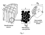
- the preferred material is a synthetic porous carbon the structure of which is shown schematically in Figure 1 .
- porous is meant that the carbon has continuous channels through which liquid or vapours can pass combined with a micro-macroporous structure within the walls of the monolith.
- the porous carbon is in a single piece i. e. not granular.
- the monolithic carbon contains large transport channels through which the gas can flow and by which means the pressure drop can be controlled.
- the channel structure is defined by the wall thickness, t, and the channel size, W.
- the monoliths have a cell structure (cells per square inch - cpi) where the channel size, W, is between 100 and 2000 ⁇ m and the wall thickness, t, is between 100 and 2000 ⁇ m and with an open area of between 30 and 80% to give a good carbon packing density per unit volume and acceptable mass transfer characteristics.
- the monolithic heater also functions as an adsorber.
- the monolith preferably has a surface area of at least 450m 2 /g, preferably in excess of 700m 2 /g.
- the surface area derives from the structure within the monolith walls which is both macro and micro porous.
- the macro porosity derives from the voids between the primary particles that make up the wall area that are comprised of primary particles with a mean size, D p , of between 10 ⁇ m and 100 ⁇ m but where the maximum mean particle size is ⁇ 10% of the wall thickness, W.
- the microporosity derives from the internal porosity of the primary particles that is generated by the voids between the micro-domains, d p , created from the domains present in the original resin structure ( fig. 1 ).
- the monoliths can be produced in lengths from around I mm to 200 cm but in the present invention this will depend on the use.
- the monolithic porous carbon can be made by partially curing a phenolic resin to a solid, comminuting the partially cured resin, extruding the comminuted resin, sintering the extruded resin so as to produce a form-stable sintered product and activating the form-stable sintered product.
- WO 02/072240 (Application GB 01 06082.1 ) gives details of methods of forming the porous carbons suitable for the porous carbon used in the present invention and its contents are included herein by reference.
- the process comprises (a) partially curing a phenolic resin to a solid, (b) grinding the solid to form particles, (c) forming the resulting ground product into a dough and extruding to a pre-determined shape at a pressure in the range 0 to 20 MPa, (d) sintering the shaped solid so as to produce a form-stable sintered product.
- the sintered product is then carbonised and activated.
- these domains are microporous with an initial surface area of typically ⁇ 450m 2 /g but that can be increased to > 1000m 2 /g by controlled activation.
- Phenolic resins are well known materials. They are made by the reaction of a phenol and an aldehyde e. g. formaldehyde. The condensation is initially carried out to produce a partially condensed product. The condensation may be carried out so as to produce a resin which is fully curable on further heating. Alternatively the condensation may be carried out so as to produce a novolak resin which is only curable when an additional cross-linking agent is mixed with it e. g. hexamethylene tetramine (known as "hexamine” o r "hex"). It is preferred to use h examine-cured novolak resins in the process of the present invention.
- the resin cure should be controlled so that it is sufficient to prevent the resin melting during subsequent carbonization but low enough so that the resin particles produced during the milling step can sinter during subsequent processing.
- the temperature and duration of the partial curing step is selected as to give a degree of cure sufficient to give a sinterable product, and being such that a sample of the partially cured solid, when ground to produce particles in the size range 106-250 microns and tabletted in a tabletting machine, gives a pellet with a crush strength which is not less than 1 N/mm.
- the pellet after carbonization has a crush strength of not less than 8 N/mm.
- sintering we mean a step which causes the individual particles of phenolic resin to adhere together without the need for a separately introduced binder, while retaining their individual identity to a substantial extent on heating to carbonisation temperatures. Thus the particles must not melt after forming so as to produce a molten mass of resin, as this would eliminate the internal open porosity of the article.
- the open porosity (as opposed to the closed cells found in certain types of polymer foams) is believed to be important in enabling formed articles to retain their shape on carbonization.
- the comminuted resin particles have a particle size of 1 to 250 ⁇ m.
- the resin powder size is between around 5 ⁇ m and 200 ⁇ m which provides for a macropore size of between I and 40 ⁇ m with a macropore volume of around 40%.
- the milled powder can then be extruded to produce polymeric monolithic structures with a wide range of cell structures, limited only by the ability to produce the required extrusion die. Production of the monoliths is greatly facilitated by the extrusion of the cured resin powder rather than of a more abrasive ceramic or carbon powder. At this stage the monolith has a bimodal structure-the visible cell structure with open cells of around 100 to 2000 ⁇ m cell dimension and cell walls with thickness between around 100 and 2000 ⁇ m - and the macropore structure within the walls generated by the sintered resin particles.
- the carbonization steps take place preferably by heating above 600°C, e. g. 600°C to 800°C and typically 700°C for the requisite time e. g. 1 to 48 hours but at a sufficient temperature so that an electrically conducting matrix is generated with the required resistivity properties.
- the process takes place under an inert atmosphere or vacuum to prevent oxidation of the carbon.
- the macropore size is also reduced by ⁇ 30% although the macropore volume (ml/ml) remains unaltered.
- the microstructure of the porous carbon develops.
- the monolith behaves as a molecular sieve due to partial blocking of the microstructure by the decomposition products from the carbonization process. These blockages must be removed to provide rapid access to the internal structure of the carbon that is essential for the operation of the monoliths as combined low pressure drop adsorbers and heaters.
- the monolithic porous carbon can be activated to provide an enhanced pore volume and surface area.
- Activation can take place in either steam or carbon dioxide at temperatures above approximately 750°C and 850°C respectively or in combinations of these gases.
- the activation process is carried out for a time that varies with the temperature and the activation gas composition, such that a carbon weight loss of between 20 and 40% is achieved.
- Preferably the activation is carried in CO 2 at 850 to 1000°C.
- Such activation is not, however, a prerequisite for the heating devices of the current invention except where the device is required to function both as a heater and an adsorber. Activation will also lead to changes in the resistivity of the carbon as a function primarily of the temperature and time activation conditions.
- the monolithic carbons are resistant to high temperatures and are biologically inert.
- Patent application WO 03/008068 discloses an improved method of forming complex carbon forms by sintering partially cured phenolic resin powders.
- the novolak resin precursor is partially cured using hexamethylene tetramine (Hexamine) to an extent sufficient to just convert the thermoplastic novolak to a thermoset resin.
- the resin is then milled to a powder with a particle size of between 5 and 500 ⁇ m, mixed with an extrusion aid such as methyl cellulose to form a dough, and extruded to produce complex monolith structures which, after drying, can be carbonized and activated.
- the formed carbons have a very uniform structure, exhibit good thermal and electrical conductivity and can be produced with surface areas up to around 1000m 2 /g.
- the synthetic porous carbon monoliths have a high heat transfer efficiency that derives from a combination of the very high heat exchange surface area that is attainable within small cell structures and the ability to directly heat all of this available surface by passing an electric current through the monolith.
- the synthetic monoliths have a cell density, produced according to our co- pending applications referred to above, with cell densities up to 930 cells/cm 2 (6000 cells per square inch).
- Table 1 shows the available heat transfer surface area per unit volume as a function of cell density and cell geometry.
- the heat transfer efficiency of the monoliths is related to the Reynolds number of the gas stream within the monolith. The low pressure drop characteristics of the monoliths allows operation at high linear velocities without excessive pressure drop penalties so that the high Reynolds numbers can be achieved without requiring feed gas compression or through the use of vacuum to draw gas through the monoliths.
- the carbon monoliths used in the present invention can be electrically heated in a highly controlled fashion. For many applications a key requirement in general is to be able to operate at low voltages that are matched to the system supply. This could be around 12 volts in vehicle applications and around 30 volts in satellite applications and military applications. These low voltages also provide for additional safety as the potential for arcing is minimized. With the monoliths useful in the present invention the resistance of the monolith can be matched to the required heat input, which is critical in many applications.
- the resistance of the synthetic carbon monoliths can be varied over a very wide range through precise control of the resin monolith carbonization or pyrolysis temperature and that, surprisingly the residence time at the pyrolysis temperature also seriously impacts on the resistance.
- Carbon also possesses the well known but unique property that the resistance decreases as the temperature increases preventing runaway.
- a further unique property of the carbon monoliths is that the temperature coefficient of resistivity is also a strong function of the pyrolysis conditions where the temperature coefficient increases as the resistance increases.
- An embodiment enables the electrical resistance of a porous synthetic carbon monolith to be controlled by a method which comprises (a) partially curing a phenolic resin to a solid, (b) grinding the solid to form particles, (c) forming the resulting ground product into a dough and extruding to a pre-determined shape at a pressure in the range 0 to 20 MPa, (d) sintering the shaped solid so as to produce a form-stable sintered resin product and (e) pyrolysing the form stable porous resin product to produce a carbon monolith in which the electrical resistivity of the monoliths is controlled by varying the pyrolysis temperature and the residence time at the pyrolysis temperature.
- the resistivity is dependent on the duration and temperature of the pyrolysis step and resistivities from around 700 ohm.cm to less than 1 ohm.cm can be achieved at pyrolysis temperatures between 600 and 800°C respectively. This resistivity can be further reduced to less than 0.1 ohm.cm by increasing the pyrolysis temperature to > 2000°C.
- the resistivity of the carbon can also be increased in a controlled fashion by introducing surface oxygen. This can be achieved by holding the carbon materials in air at temperatures from 100 to 500°C, preferably between 150 and 400°C, for varying times or by chemical activation methods including but not limited to treatment with nitric acid, hydrogen peroxide, sodium hypochlorite or any other known oxidizing agent.
- the ability to carry out this modification decreases as the heat treatment temperatures increase such that by 1500°C it is difficult to increase the resistance.
- the optimum treatment temperature is in the range 1300-1400°C which provides a good balance of stability in air operation with the ability to increase the resistance.
- the slight air activation used in this process has the further benefit of reintroducing a significant surface area if the heater is also to be used as an adsorption device.
- activated carbons are ideally suited to the adsorption of gasoline vapours the critical problem is regeneration of the canister. Regeneration is only achieved by drawing cold, clean air through the canister when the vehicle is operational. This is in marked contrast to industrial carbon systems where the canister temperature is raised to perhaps 200°C to drive off the adsorbed vapours. This places major constraints on the carbon to be used in the vehicle emission canisters.
- the majority of activated carbons are highly microporous (pores of less than 2 nanometres diameter) and these very small pores then give rise to the large surface area (in excess of 1000 m 2 /gm) that is responsible for the high adsorption capacity of the carbons (in excess of 50% wt for aromatics).
- the critical parameter in these canister carbons is the "working capacity" which is a measure of the hydrocarbon adsorption capacity after several adsorption-desorption cycles using the cold gas desorption process. The effect of this is that, even for a more weakly adsorbing hydrocarbon such as butane, the working capacity in a microporous carbon is only perhaps 6% weight, compared to a first cycle capacity of perhaps 50% weight, which then defines the canister size.
- FIG. 5 One example of a purge heater design is illustrated in figure 5 .
- the monolith structure is controlled by a combination of the required resistivity during regeneration and the allowable pressure drop during refuelling.
- the flow through the monoliths is between approximately 2 and 20 litres/minute depending on vehicle operation (high flow during idling and low flow with the engine at maximum output), whilst during refuelling this can rise to 50L/minute during which the pressure drop through the complete canister-purge heater assembly should not exceed 100Pa.
- the number of monoliths is controlled primarily by the allowable pressure drop and the resistance required to generate the desired power.
- the primary variable in the heat generation is the power consumption (watts) which at the vehicle voltage (12V) is then controlled by the monolith resistance.
- watts the power consumption
- the low pressure drop requires a large monolith cross section and short monolith length whilst the resistance requires a smaller cross section and longer length.
- the resistivity should not be so low that the contact resistances within the device comprise a significant part of the overall system resistance.
- the total monolith resistance should be more than 50% of the overall device resistance.
- the maximum resistivity than can be tolerated is fixed by the power requirements. Two monoliths, 1.5cm in diameter, would require a resistivity of 0.85ohm.cm whilst a single monolith would need to be 2cm in diameter, with the same open area as the existing monoliths (65%) to give the required pressure drop, with a resistance of approximately 4ohm, equivalent to a resistivity of approximately 2.5ohm.cm. However in this case considerably more care would need to be taken to achieve an even power distribution across the monolith. This resistance could be achieved using a 30mm diameter ceramic-carbon composite monolith, as described in US 5914294 .
- FIG. 5 One embodiment of the device that uses 4 monoliths is shown in figure 5 .
- the four monoliths (6) are held at each end in copper connectors (9). These are interconnected by copper connectors (7) to achieve the series electrical connections.
- the monolith and copper connector assemblies are held inside the purge heater body by springs (3), two of which also provide the electrical connection to the external power connectors (8). Gas flow through the body is through the entry port (4), over the external surface of the monolith housings, passing through the monoliths and exiting via the outlet port (5). This prevents the external surface of the heater from getting too hot and helps to minimise heat losses.
- this purge heater was instrumented by fixing temperature probes to the monolith surfaces at the inlet (1) and outlet (2).
- the monolith is thermally treated at 1300°C it can be used for extended periods at 170°C with only very small changes in resistivity.
- Heat treatment at 1300°C has the further benefit that the resistance can be increased by controlled air oxidation that also increases the available surface area.
- the monolith is less stable whilst at 1500°C the monolith is very stable but increasing the resistance and the surface area by controlled oxidation becomes progressively more difficult.
- the air stability of the carbon-ceramic monolith of US 5914294 is shown in figure 13 compared to the synthetic carbon monoliths. It can be seen that the ceramic carbon composite has a much higher resistivity and demonstrates a significant air instability although this is less than shown by the synthetic carbon monolith prepared at 800°C. This improved stability (30% increase in 200 hours) can be attributed to the higher preparation temperature of the carbon ceramic monolith, claimed in US 5914294 to be in excess of 1000°C. This can be compared with the thermally stabilised synthetic carbon monoliths in figure 6 where the monoliths treated at 1300°C demonstrated very little change in resistance after 1200hours in air at 200°C. The level of stability demonstrated is unlikely to be sufficient for long term operation at the target heater temperature of 170°C but could be usable at a lower heater temperature.
- propulsion devices are used for: (a) Orbit injection correction; (b) Phasing of each satellite with the others in a cluster and (c) Drag mitigation,
- hydrazine monopropellants are preferred for attitude control and orbit correction.
- the cost of designing a system to use hydrazine, and the associated costs partially negate the cost-effectiveness of small satellites.
- a green propellant based small satellite propulsion system with an activation time comparable to a hydrazine system (in the millisecond range), and potentially useable for attitude control would enable a highly marketable, low cost manoeuvering and attitude control capability and (v) future small satellite missions are likely to make extensive use of xenon propellant, because of its gaseous nature (no slosh effects) and high storage density.
- xenon is a low performance propellant, offering an Isp of around 50s compared to 90s for butane in the same low power resisto-jet.
- the thruster must be run at the highest temperature possible. Thruster Isp is approximately proportional to temperature, so as to achieve a similar performance to butane it will require operation in excess of 1000°C. This is beyond the capability of the current design and is not feasible with butane which thermally cracks to give carbon (clogging the thruster) above ⁇ 450°C.
- the monolith systems based on the materials of the invention are capable of heating the required gas flows ( ⁇ 2L/minute) to temperatures in excess of 400°C using the power available on small satellites (approx 30W) with very high efficiency and over short time cycles and of maintaining the temperature for extended periods. This eliminates both the time required for heat-up ( ⁇ 1 orbit for conventional systems) and the short firing time accessible with current heated wire systems.
- the monoliths have the additional benefit of showing essentially zero pressure drop, allowing the full pressure drop to be developed across the thruster exit nozzle for maximum thrust efficiency.
- this device is shown in the test device used to evaluate the application in figure 7 and comprises the carbon monolith (14) mounted in a high temperature ceramic body (12) with ceramic paper insulant (13) to prevent gas bypassing the monolith.
- the monolith is held between copper connectors (11) that are connected to the gas inlet (17) and outlet (18) via springs (15).
- the gas inlet and outlets are sealed to the ceramic body by washers (16) to allow the device to operate at pressure.
- One method for analysis of trace amounts of organics is to concentrate the material into activated carbon and then to thermally desorb the adsorbate into the analyser.
- the effectiveness of such systems is limited by the rate at which the carbon can be heated and the temperature to which it can be heated. In the case of granular carbons this is limited by the heat transfer ability of the granular bed which actually functions as a good insulator.
- the monoliths can be heated to temperatures in excess of 1000°C in a few seconds using very low power allowing even high molecular adsorbates to be rapidly desorbed.
- the structure of the monolith allows this to be removed from a sampling environment and loaded into the analyser containing the electrical heating supplies or for a complete system to be connected to the analyser. The power required for such a system would be around 50W for temperatures in excess of 1000°C but depends on the purge gas flow required.
- Stainless steel trays 30cm square and 5cm deep were filled with a powder comprising a standard commercial Novolak, supplied by Borden Chemicals with a code number of J1011S.
- the trays were then placed on a trolley inside a curing oven and the cure was carried out by raising the temperature to 100°C over a period of 1.5 hours, holding at 100°C for 1 hour, raising the temperature to 150°C over a further 1 hour and holding at 150°C for 1 hour.
- the cured block was then hammer milled to give a coarse powder of greater than 90microns particle size.
- the hammer milled powder was then jet milled using a Hozakawa 100AFG jet mill to give a mean particle size of 50microns.
- 1Kg of the jet milled powder was then formed into a dough in a Z-blade mixer using approximately 500g of water and standard polymeric extrusion aids - Methocell and polyethylene oxide.
- the dough was then extruded using a high pressure ram extruder at a pressure of around 40bar using a conventional monolith die.
- the extruded monolith was air dried for at least 12 hours by rotating slowly in ambient air to ensure it remained straight, although more rapid drying can be achieved using, for instance, air less drying.
- the monoliths had a diameter in the resin form of 10mm with a length of 10cm. These monoliths were then carbonised in flowing carbon dioxide at temperatures of between 650 and 720°C with residence times at temperature of between 1 and 12 hours.
- the resistance is strongly dependent upon both the pyrolysis temperature and the residence time.
- the variation in resistance with residence time is surprising as there is little or no change in the monolith weight or size. Without being bound to this explanation we believe that this resistance variation is caused by the presence of small amounts of high molecular weight molecules adsorbed onto the carbon surface that withdraw electrons from the carbon conduction bands leading to the higher resistance. These can only then be removed by holding for extended times where the time increases as the pyrolysis temperature decreases.
- the effect of residence time on resistivity for carbonisation at 650 and 660°C is also shown in Figure 8 . It can be seen that minimum resistance is reached at 650°C only for hold times in excess of approximately 9 hours.
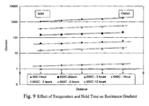
- the gradient of resistance along the monoliths is also a function of the temperature and time, with the resistance increasing along the tube. This is shown in figure 9 . It can be seen that the gradient of resistance along the monolith decreases with the total resistance. We believe this is also due to the presence of impurities adsorbed on the carbon surface that are progressively removed along the length of the monolith with time on stream. This effect is reduced for shorter monolith segment lengths where the diffusion path length is shorter.
- the resistance can be further reduced by heating the monoliths in a high temperature furnace in an inert gas such as helium or argon.
- an inert gas such as helium or argon.
- the resistivity of the pyrolysed and heat treated carbon can be modified in a controlled fashion by introducing surface oxygen by holding the carbon materials in air at temperatures from 150 to 500°C, preferably between 200 and 400°C, for varying times where the temperature varies with the severity of the heat treatment.
- the temperature required to bring about this effect varies with the initial heat treatment temperature.
- the effect of oxidation is as shown in figure 6 with a significant increase in resistance at only 200°C over 200 hours.
- higher oxidation temperatures are required to achieve the desired increase in resistance.
- This combination of high temperature heat treatment and oxidation can be used to produce stable, controlled resistance monoliths, for use when heating gas streams containing oxygen.
- the heating performance of the carbon monoliths for use in the resisto-jet application has been measured using the device shown in figure 7 .
- the monoliths are held between small shaped copper washers held in place with springs within a ceramic housing that allows operation at temperatures up to 1000°C.
- the end fittings allow the device to be operated at pressures up to 3bar absolute. Power is supplied to the monoliths via the springs with a maximum power input based on the available power supply of 60W (30V at 2A in a satellite system), although this is limited by the resistance characteristics of the monolith.
- the maximum monolith length in this device is 1-5cm.
- Thermocouples are mounted such that one sits just above the monolith surface measuring exit gas temperature and the second is mounted just inside the exit of the monolith.
- Gas preferably nitrogen or argon
- Heating efficiency is quoted as the heat content of the gas exiting the monolith divided by the electrical input energy from the controlled power supply.
- the heating efficiency as a function of gas Reynolds number is shown in fig. 10 .
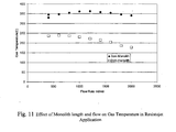
- a further unique property of the monolith is shown in fig. 11 , which demonstrates the insensitivity of the exit gas temperature to gas flow through the monolith at constant applied voltage. It can be seen that for the longer monolith the gas temperature remains essentially constant at flows ranging from 400 to 2000ml/min.
- the potential of the carbon monoliths in automotive purge heating has been measured using the device shown in figure 5 .
- This device holds four 10mm diameter x 5cm long monoliths. These were prepared with a high open area (64%, 1200micron channel size) to minimise pressure drop and a thin wall structure (300 micron) to give the required resistivity, equivalent to a resin cell density of approximately 300 cells per square inch in the resin and 600 cells per square inch in the carbonised monolith.
- the monoliths used were prepared according to Example 1 using 10 micron milled resin powder. The dried monoliths were carbonised at 800°C in flowing carbon dioxide for 45 minutes. The reduced residence was used as the subsequent high temperature thermal treatment had the same effect. They were then thermally stabilised in helium at 1300°C for 30 minutes.
- the monoliths were subsequently treated in air at 380°C for 4 hours to increase the resistance to the required level. After this series of treatments the monoliths had a typical resistance of ⁇ 0.076+/-0.005ohm/cm.
- the monoliths were mounted in the purge heater as shown in figure 5 with a surface thermocouple attached to each monolith close to the inlet and outlet.
- the purge heater was then connected to the purge air inlet of the standard MahleTennex LEVII canister, shown in figure 4 , filled with 2.5L of highly mesoporous BAX1100 carbon.
- This canister was instrumented with 7 thermocouples, six in the carbon beds and one (TC1) in the air inlet to the canister. Within the beds 4 of the probes were in the second chamber of the canister (TC2-TC5) and two were in the first, main chamber (TC6 and TC7).
- the assembly was then subjected to several adsorption-regeneration cycles, with and without the purge heater, using pentane as the challenge vapour.
- the adsorption cycles were carried out by passing 1 L/minute of air through a pentane saturator held at 10°C and then through the canister via line 1 leaving the canister via line 2.
- the adsorption cycle was continued until pentane breakthrough was detected in line 2.
- air at 10L/minute was passed through the purge heater, entering the canister via line 2 and leaving via line 3. Regeneration was continued for 30 minutes to give a total regeneration flow of 300L, equivalent to 120 bed volumes.
- FIG 14a A typical temperature profile in the canister and purge heater, without the purge heater in operation during regeneration, is shown in figure 14a .
- the frontal adsorption of pentane through the canister can be seen with the temperature in the main, first, chamber rising initially to approximately 40°C and the 4 zones in the second chamber reaching 47°C, 47°C, 63°C and 71°C respectively.
- Total pentane adsorption in this test was approximately 65g.
- the temperature rise is indicative of the amount of pentane adsorbed and can be compared with temperatures of approximately 75°C in all zones for a clean canister when the total pentane uptake was approximately 250g.
Landscapes
- Solid-Sorbent Or Filter-Aiding Compositions (AREA)
- Resistance Heating (AREA)
- Direct Air Heating By Heater Or Combustion Gas (AREA)
- Cooling, Air Intake And Gas Exhaust, And Fuel Tank Arrangements In Propulsion Units (AREA)
- Physical Or Chemical Processes And Apparatus (AREA)
Abstract
Description
- The present invention relates to a heater element and a heater incorporating the element and it particularly relates to a heater which can be used for heating fluids such as gases.
- Conventional gas heating systems rely on the use of indirect heating via gas fired or electrically heated tubes, as in traditional heat exchangers, or via direct heating using electrical elements. However there are a large number of potential applications where gas heating is a critical requirement and where the known systems cannot be used and there is a need for an improved system. The major disadvantage of these traditional systems when applied to smaller applications or to lower temperature process streams is their poor heating efficiency that then leads to high surface temperatures relative to the required process temperature. This leads to severe problems when the stream to be heated is thermally unstable and where the stream is combustible and high surface temperatures could lead to ignition or where the power availability is limited.
-
US-A-3982100 (Hervert; Universal Oil Products Company) discloses forms of honeycomb or other extended surface as electrical resistance elements and heater devices. It further discloses methods for making rigid, monolithic semiconductive elements from the mixing of a conductive carbonaceous pyropolymer with a nonconductive ceramic substrate. The honeycomb form of electric heating element is said to be of particular advantage in that it provides a high surface area heat exchange surface that, in turn, can effect a rapid, efficient heat transfer to a gaseous or liquid media that may be passed through the channels of the element. In an embodiment there is provided a resistance heating element, which comprises, an extended surface area conductive rigid ceramic-pyropolymer member that results from the admixture of conductive subdivided refractory particles (e.g. of γ-alumina, silica, magnesia, boria or thoria) having a coating of a carbonaceous pyropolymer thereon with a primarily crystalline ceramic type material which can be thermally rigidified, and where said coating on the refractory particles has a conductivity of from about 10-8 to about 102 inverse ohm-centimeters resulting from heating an organic pyrolyzable substance in a primarily non-oxidizing atmosphere in contact with the particles at a temperature above about 400°C. A wide range of organic materials is disclosed as suitable materials that may be polymerized to form the pyropolymer. The ceramic material may be sillimanite, magnesium silicates, silicates, zircon, petalite, spodumene, cordierite, aluminosilicates, mullite, and of mixtures of several of the aforesaid materials. -
EP-A-0684071 (Gadkaree, Coming ) discloses a body comprising an activated carbon structure e.g. in the form of a honeycomb having means for passage of a workstream therethrough; and conducting means on the structure for conducting an electric current therethrough, wherein the activated carbon structure is a non-electrically conducting monolithic inorganic substrate coated with a continuous uninterrupted layer of activated carbon, the activated carbon being derived from a carbon precursor. The activated carbon coating may be made by (a) contacting the inorganic substrate with a carbon precursor e.g. a thermosetting resin, (b) curing the carbon precursor, (c) carbonizing the cured carbon precursor to form a uniform coating of carbon on the substrate, and (d) activating the carbon. -
WO 02/072240 (Place et al. -
EP-A-0310043 (Sarin, GTE Laboratories Inc. ) discloses oxidation resistant, high temperature thermal cycling resistant coated ceramic article for ceramic heat engine applications. The substrate is a silicon-based material, i.e. a silicon nitride- or silicon carbide-based monolithic or composite material. -
US-A-6263665 (Muntz, United States) discloses an electrical heater for a satellite microthruster. - In one aspect, this invention provides a heater for fluids in which a fluid is passed along continuous channels through a heater element which is an electrically conductive porous carbon monolith (6), characterized in that:
- (a) the channels through the monolith define a cell structure in which the channel size is 100 - 2000 µm and the wall thickness is 100 - 2000 µm with an open area of 30 - 60%;
- (b) the walls are of carbon particles of mean size 10 -100 µm, the mean particle size being <10% of the wall thickness;
- (c) the monolith is macro and microporous, the macroporosity deriving from voids between the carbon particles and the microporosity deriving from internal porosity of the carbon particles generated by voids between micro-domains of said particles.
- In another aspect, the invention provides a method of forming an electrically conductive synthetic porous carbon monolith in which (a) the channels through the monolith (6) define a cell structure in which the channel size is 100 - 2000 µm and the wall thickness is 100 - 2000 µm with an open area of 30 - 60%, (b) the walls are of carbon particles of mean size 10 - 100 µm, the mean particle size being <10% of the wall thickness, and (c) the monolith is macro and microporous, the macroporosity deriving from voids between the carbon particles (DP) and the microporosity deriving from internal porosity of the carbon particles generated by voids between micro-domains (dp) of said particles, said monolith being obtained by:
- partially curing a phenolic resin to a solid;
- comminuting the partially cured resin;
- extruding the comminuted resin;
- sintering the extruded resin so as to produce a form-stable sintered product
- The porous monolithic element is a porous synthetic carbon monolith and its effectiveness is thought to derive from its unique combination of controlled resistivity and controlled structure. The preferred material is a synthetic porous carbon the structure of which is shown schematically in
Figure 1 . - By "porous" is meant that the carbon has continuous channels through which liquid or vapours can pass combined with a micro-macroporous structure within the walls of the monolith.
- By "monolith" and "monolithic" is meant that the porous carbon is in a single piece i. e. not granular. The monolithic carbon contains large transport channels through which the gas can flow and by which means the pressure drop can be controlled. The channel structure is defined by the wall thickness, t, and the channel size, W.
- The monoliths have a cell structure (cells per square inch - cpi) where the channel size, W, is between 100 and 2000 µm and the wall thickness, t, is between 100 and 2000 µm and with an open area of between 30 and 80% to give a good carbon packing density per unit volume and acceptable mass transfer characteristics.
- In some applications it may be desirable that the monolithic heater also functions as an adsorber. In this case the monolith preferably has a surface area of at least 450m2/g, preferably in excess of 700m2/g. The surface area derives from the structure within the monolith walls which is both macro and micro porous. The macro porosity derives from the voids between the primary particles that make up the wall area that are comprised of primary particles with a mean size, Dp, of between 10 µm and 100 µm but where the maximum mean particle size is < 10% of the wall thickness, W. The microporosity derives from the internal porosity of the primary particles that is generated by the voids between the micro-domains, dp, created from the domains present in the original resin structure (
fig. 1 ). - The monoliths can be produced in lengths from around I mm to 200 cm but in the present invention this will depend on the use.
- The monolithic porous carbon can be made by partially curing a phenolic resin to a solid, comminuting the partially cured resin, extruding the comminuted resin, sintering the extruded resin so as to produce a form-stable sintered product and activating the form-stable sintered product.
-
WO 02/072240 GB 01 06082.1 range 0 to 20 MPa, (d) sintering the shaped solid so as to produce a form-stable sintered product. The sintered product is then carbonised and activated. - After carbonization these domains are microporous with an initial surface area of typically ~ 450m2/g but that can be increased to > 1000m2/g by controlled activation.
- Phenolic resins are well known materials. They are made by the reaction of a phenol and an aldehyde e. g. formaldehyde. The condensation is initially carried out to produce a partially condensed product. The condensation may be carried out so as to produce a resin which is fully curable on further heating. Alternatively the condensation may be carried out so as to produce a novolak resin which is only curable when an additional cross-linking agent is mixed with it e. g. hexamethylene tetramine (known as "hexamine" o r "hex"). It is preferred to use h examine-cured novolak resins in the process of the present invention.
- The resin cure should be controlled so that it is sufficient to prevent the resin melting during subsequent carbonization but low enough so that the resin particles produced during the milling step can sinter during subsequent processing. Preferably the temperature and duration of the partial curing step is selected as to give a degree of cure sufficient to give a sinterable product, and being such that a sample of the partially cured solid, when ground to produce particles in the size range 106-250 microns and tabletted in a tabletting machine, gives a pellet with a crush strength which is not less than 1 N/mm. Preferably the pellet after carbonization has a crush strength of not less than 8 N/mm.
- By "sintering" we mean a step which causes the individual particles of phenolic resin to adhere together without the need for a separately introduced binder, while retaining their individual identity to a substantial extent on heating to carbonisation temperatures. Thus the particles must not melt after forming so as to produce a molten mass of resin, as this would eliminate the internal open porosity of the article.
- The open porosity (as opposed to the closed cells found in certain types of polymer foams) is believed to be important in enabling formed articles to retain their shape on carbonization.
- In one embodiment the comminuted resin particles have a particle size of 1 to 250 µm. Preferably the resin powder size is between around 5 µm and 200 µm which provides for a macropore size of between I and 40 µm with a macropore volume of around 40%.
- The milled powder can then be extruded to produce polymeric monolithic structures with a wide range of cell structures, limited only by the ability to produce the required extrusion die. Production of the monoliths is greatly facilitated by the extrusion of the cured resin powder rather than of a more abrasive ceramic or carbon powder. At this stage the monolith has a bimodal structure-the visible cell structure with open cells of around 100 to 2000 µm cell dimension and cell walls with thickness between around 100 and 2000 µm - and the macropore structure within the walls generated by the sintered resin particles.
- The carbonization steps take place preferably by heating above 600°C, e. g. 600°C to 800°C and typically 700°C for the requisite time e. g. 1 to 48 hours but at a sufficient temperature so that an electrically conducting matrix is generated with the required resistivity properties. The process takes place under an inert atmosphere or vacuum to prevent oxidation of the carbon.
- On carbonization the material loses around 50% weight and shrinks by 50% volume but, provided the resin cure stage was correctly carried out, this shrinkage is accommodated with no distortion of the monolith matrix leading to a cell structure identical to that of the resin precursor but with dimensions reduced by approx 30%.
- The macropore size is also reduced by ~ 30% although the macropore volume (ml/ml) remains unaltered.
- At this stage the microstructure of the porous carbon develops. After carbonization the monolith behaves as a molecular sieve due to partial blocking of the microstructure by the decomposition products from the carbonization process. These blockages must be removed to provide rapid access to the internal structure of the carbon that is essential for the operation of the monoliths as combined low pressure drop adsorbers and heaters.
- After carbonisation the monolithic porous carbon can be activated to provide an enhanced pore volume and surface area. Activation can take place in either steam or carbon dioxide at temperatures above approximately 750°C and 850°C respectively or in combinations of these gases. The activation process is carried out for a time that varies with the temperature and the activation gas composition, such that a carbon weight loss of between 20 and 40% is achieved. Preferably the activation is carried in CO2 at 850 to 1000°C. Such activation is not, however, a prerequisite for the heating devices of the current invention except where the device is required to function both as a heater and an adsorber. Activation will also lead to changes in the resistivity of the carbon as a function primarily of the temperature and time activation conditions.
- The monolithic carbons are resistant to high temperatures and are biologically inert.
- Patent application
WO 03/008068 PCT/GB2002/003259 - The synthetic porous carbon monoliths have a high heat transfer efficiency that derives from a combination of the very high heat exchange surface area that is attainable within small cell structures and the ability to directly heat all of this available surface by passing an electric current through the monolith.
- Preferably the synthetic monoliths have a cell density, produced according to our co- pending applications referred to above, with cell densities up to 930 cells/cm2 (6000 cells per square inch). Table 1 below shows the available heat transfer surface area per unit volume as a function of cell density and cell geometry. We have also shown that the heat transfer efficiency of the monoliths is related to the Reynolds number of the gas stream within the monolith. The low pressure drop characteristics of the monoliths allows operation at high linear velocities without excessive pressure drop penalties so that the high Reynolds numbers can be achieved without requiring feed gas compression or through the use of vacuum to draw gas through the monoliths.
Table 1 Cell CPI Resin Pin Size mm Contact area cm2/cm Fraction open area micro 2687 0.4 19.8 0.673 small 779 8.8 11.48 0.64 medium 585 0.9 9.7 0.621 large 364 1.2 8.06 0.601 tube 0.6 2.2 0.857 cpi = cells per square inch - The carbon monoliths used in the present invention can be electrically heated in a highly controlled fashion. For many applications a key requirement in general is to be able to operate at low voltages that are matched to the system supply. This could be around 12 volts in vehicle applications and around 30 volts in satellite applications and military applications. These low voltages also provide for additional safety as the potential for arcing is minimized. With the monoliths useful in the present invention the resistance of the monolith can be matched to the required heat input, which is critical in many applications.
- We have now found that the resistance of the synthetic carbon monoliths can be varied over a very wide range through precise control of the resin monolith carbonization or pyrolysis temperature and that, surprisingly the residence time at the pyrolysis temperature also seriously impacts on the resistance. Carbon also possesses the well known but unique property that the resistance decreases as the temperature increases preventing runaway. We have now found that a further unique property of the carbon monoliths is that the temperature coefficient of resistivity is also a strong function of the pyrolysis conditions where the temperature coefficient increases as the resistance increases.
- An embodiment enables the electrical resistance of a porous synthetic carbon monolith to be controlled by a method which comprises (a) partially curing a phenolic resin to a solid, (b) grinding the solid to form particles, (c) forming the resulting ground product into a dough and extruding to a pre-determined shape at a pressure in the
range 0 to 20 MPa, (d) sintering the shaped solid so as to produce a form-stable sintered resin product and (e) pyrolysing the form stable porous resin product to produce a carbon monolith in which the electrical resistivity of the monoliths is controlled by varying the pyrolysis temperature and the residence time at the pyrolysis temperature. - The resistivity is dependent on the duration and temperature of the pyrolysis step and resistivities from around 700 ohm.cm to less than 1 ohm.cm can be achieved at pyrolysis temperatures between 600 and 800°C respectively. This resistivity can be further reduced to less than 0.1 ohm.cm by increasing the pyrolysis temperature to > 2000°C.
- The resistivity of the carbon can also be increased in a controlled fashion by introducing surface oxygen. This can be achieved by holding the carbon materials in air at temperatures from 100 to 500°C, preferably between 150 and 400°C, for varying times or by chemical activation methods including but not limited to treatment with nitric acid, hydrogen peroxide, sodium hypochlorite or any other known oxidizing agent.
- We have also found that where it is desired to use the heater device in an air stream it is important that the monoliths are stabilized by high temperature thermal treatment. If the synthetic carbon monoliths pyrolysed at temperatures below 1300°C are used in air at temperatures up to 200°C the resistance changes dramatically during use and this can cause premature failure due to local over heating. This can be avoided by heat treating a monolith initially pyrolysed at 800°C to at least 1300°C. The stability increases with the heat treatment temperature but for operation at 200°C, treatment at 1300°C is sufficient. A drawback to this is that the resistance is decreased significantly and may then be too low to match the operating voltage and current requirements. Under these circumstances the resistance can then be increased by controlled high severity air oxidation. The ability to carry out this modification decreases as the heat treatment temperatures increase such that by 1500°C it is difficult to increase the resistance. The optimum treatment temperature is in the range 1300-1400°C which provides a good balance of stability in air operation with the ability to increase the resistance. The slight air activation used in this process has the further benefit of reintroducing a significant surface area if the heater is also to be used as an adsorption device.
- The combination of these flow and resistivity characteristics then provides a unique operating characteristic of these monolith heaters where, when heating a gas, the produced gas temperature is relatively insensitive to the gas flow over quite a wide volumetric flow range (see
fig. 11 ). This arises primarily from the significant increase in heat exchange efficiency with gas linear velocity. - These heat exchange properties can be applied in a wide variety of end uses covering a wide range of scales some of which are described below, and illustrated in the drawings.
- In the drawings:
-
Fig.1 shows the dimensions in porous carbon monolith; -
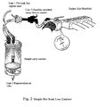
Fig. 2 shows a simple early canister system; -
Fig. 3 shows the evolution of the legislation controlling emissions; -
Fig. 4 shows a two chamber LEVII canister; -
Fig. 5 shows a purge heater design; -
Figs. 6 and8-14 show performance tables referred to in the examples and -
Fig. 7 shows a test device. - A major potential use is in vehicle evaporative emission control. Carbon canisters have been used for some time now in all gasoline engined vehicles to eliminate hot soak losses. These losses are due to gasoline vapours released from the fuel tank and the hot engine when the vehicle is stationary. The simple early canister system is shown in
figure 2 . When the vehicle is stationary the emitted vapours are passed to and adsorbed in the canister throughline 1. When the vehicle is in use air is drawn throughline 2, via the canister andline 3 to engine inlet manifold where they are combusted with the fuel. The small canisters, containing typically around500ml of activated carbon, demonstrated the problems with the use of activated carbons in this application. Whilst activated carbons are ideally suited to the adsorption of gasoline vapours the critical problem is regeneration of the canister. Regeneration is only achieved by drawing cold, clean air through the canister when the vehicle is operational. This is in marked contrast to industrial carbon systems where the canister temperature is raised to perhaps 200°C to drive off the adsorbed vapours. This places major constraints on the carbon to be used in the vehicle emission canisters. The majority of activated carbons are highly microporous (pores of less than 2 nanometres diameter) and these very small pores then give rise to the large surface area (in excess of 1000 m2/gm) that is responsible for the high adsorption capacity of the carbons (in excess of 50% wt for aromatics). However these small pores also give rise to very high heats of adsorption that then makes cold gas regeneration very difficult. The critical parameter in these canister carbons is the "working capacity" which is a measure of the hydrocarbon adsorption capacity after several adsorption-desorption cycles using the cold gas desorption process. The effect of this is that, even for a more weakly adsorbing hydrocarbon such as butane, the working capacity in a microporous carbon is only perhaps 6% weight, compared to a first cycle capacity of perhaps 50% weight, which then defines the canister size. - These early, simple, carbon canisters have now been replaced by more complex systems as the legislation covering vehicle emissions becomes tighter. The evolution of the legislation is shown in
figure 3 . In addition to the requirement to eliminate hot soak emissions they are also now required to deal with refuelling emissions (ORVR). In this case the vapour load corresponds to the volume of the fuel tank, saturated with vapour, and is displaced through the canister in the time taken to refuel the vehicle (approximately 60 litres (~ 150g) in 2minutes). This, combined with the substantial reduction in permitted fuel vapour emission, has led to the more complex chamber two chamber LEVII canisters shown infigure 4 . This has only been achieved through the use of more mesoporous carbons, but even with the increased working capacity of these carbons (~10%), this leads to a substantial increase in canister volume (2-3L of carbon). Impending legislation will require that stationary emissions are even further reduced in the near future (PZEV) as shown infigure 3 and this will require even more complex, multi-chamber canisters. This is further complicated by the transition to lower purge volume availability with future generation engines. At present with 300L purge LEV2 can be achieved through two chamber designs incorporating special carbons whilst PZEV can only be achieved through multiple chamber designs or the use of expensive monolithic carbons as exit gas traps. There is no practical way at this moment of achieving the PZEV standards with the lower purge volumes (120BV) that will be available in future generation direct injection engines. - One option is to enhance the performance of the existing, canister designs by more effective hot gas regeneration. The constraints on purge gas heaters for the canister application are complex and derive from:-
- 1) the available purge flow (2-10 1/min) and the time cycle for regeneration (~30minutes), currently around 300L but decreasing to 120L;
- 2) the carbon temperature required in the canister (minimum 80°C);
- 3) the maximum surface temperature in the heat exchanger which, for safety reasons, should not exceed 200°C in the presence of air/gasoline mixtures.
- We have now found that both the LEV2 and PZEV requirements can be potentially achieved using a purge gas heater based on the monolithic gas heaters of the current invention. One example of a purge heater design is illustrated in
figure 5 . In this design the monolith structure is controlled by a combination of the required resistivity during regeneration and the allowable pressure drop during refuelling. During purging the flow through the monoliths is between approximately 2 and 20 litres/minute depending on vehicle operation (high flow during idling and low flow with the engine at maximum output), whilst during refuelling this can rise to 50L/minute during which the pressure drop through the complete canister-purge heater assembly should not exceed 100Pa. The number of monoliths is controlled primarily by the allowable pressure drop and the resistance required to generate the desired power. The primary variable in the heat generation is the power consumption (watts) which at the vehicle voltage (12V) is then controlled by the monolith resistance. We have found that to heat 5L/minute gas from 25°C to 150°C, the temperature required to heat the granular bed to 80°C in the target regeneration time, a power input of approximately 30W is required that is readily available from the battery or the alternator. This corresponds to approximately 2.5A and to a combined resistance in the heater device of approximately 5 ohms. The low pressure drop requires a large monolith cross section and short monolith length whilst the resistance requires a smaller cross section and longer length. These conflicting requirements have led to the design shown infigure 5 where four 10mm diameter monoliths are used in parallel to provide the required cross section but are electrically connected in series to provide the necessary resistance. The resistivity of these monoliths is ~0.19ohm.cm (allowing for the open area of the monolith). The number of monoliths can be chosen to meet the design constraints but it is preferred that an even number of monoliths are used so that all electrical connections are made at one end of the heater assembly whilst the minimum number, consistent with the design constraints, should be used to minimise contact resistances and assembly cost. The preferred number is 2 or 4. Monoliths with a lower resistivity, or lower total resistance, can also be used if a power control device is used to prevent excessive current drain. However the resistivity should not be so low that the contact resistances within the device comprise a significant part of the overall system resistance. Preferably the total monolith resistance should be more than 50% of the overall device resistance. The maximum resistivity than can be tolerated is fixed by the power requirements. Two monoliths, 1.5cm in diameter, would require a resistivity of 0.85ohm.cm whilst a single monolith would need to be 2cm in diameter, with the same open area as the existing monoliths (65%) to give the required pressure drop, with a resistance of approximately 4ohm, equivalent to a resistivity of approximately 2.5ohm.cm. However in this case considerably more care would need to be taken to achieve an even power distribution across the monolith. This resistance could be achieved using a 30mm diameter ceramic-carbon composite monolith, as described inUS 5914294 . - One embodiment of the device that uses 4 monoliths is shown in
figure 5 . The four monoliths (6) are held at each end in copper connectors (9). These are interconnected by copper connectors (7) to achieve the series electrical connections. The monolith and copper connector assemblies are held inside the purge heater body by springs (3), two of which also provide the electrical connection to the external power connectors (8). Gas flow through the body is through the entry port (4), over the external surface of the monolith housings, passing through the monoliths and exiting via the outlet port (5). This prevents the external surface of the heater from getting too hot and helps to minimise heat losses. In the results discussed in the examples this purge heater was instrumented by fixing temperature probes to the monolith surfaces at the inlet (1) and outlet (2). - However, we have found that the carbon monoliths prepared by pyrolysis at 800°C, or the ceramic carbon-composites prepared according to
US 5914294 which meet the resistance targets defined above, have insufficient stability for long term use when air is being used as the purge medium, as is essential in the purge heater application. A typical purge heater application requires an exit gas temperature from the purge heater of around 130°C at flows of up to 30L/minute that corresponds to a monolith exit temperature of approximately 170°C. Higher temperatures would be beneficial but would lead to a significant increase in material costs for the heater and canister body that should preferably be capable of production by injection moulding. - This has been evaluated using an accelerated ageing test in which the monoliths are held in air at 200°C for extended periods, equivalent to approximately 8 times longer at the proposed 170°C operating temperature. As shown in
figure 6 , at a temperature of 200°C, in the presence of air, the resistance of a synthetic carbon monolith prepared by pyrolysis at 800°C, showed poor stability. The resistance increased from approximately 0.1 ohm/cm to 0.57ohm/cm after only 200 hours at 200°C. This can then lead to local overheating as the resistance increases most rapidly in the highest temperature region, further concentrating the power usage in that region. Ultimately the monolith would undergo deep oxidation and would then fail completely. We have found, however, that if the monolith is thermally treated at 1300°C it can be used for extended periods at 170°C with only very small changes in resistivity. Heat treatment at 1300°C has the further benefit that the resistance can be increased by controlled air oxidation that also increases the available surface area. At 1200°C the monolith is less stable whilst at 1500°C the monolith is very stable but increasing the resistance and the surface area by controlled oxidation becomes progressively more difficult. - The air stability of the carbon-ceramic monolith of
US 5914294 is shown infigure 13 compared to the synthetic carbon monoliths. It can be seen that the ceramic carbon composite has a much higher resistivity and demonstrates a significant air instability although this is less than shown by the synthetic carbon monolith prepared at 800°C. This improved stability (30% increase in 200 hours) can be attributed to the higher preparation temperature of the carbon ceramic monolith, claimed inUS 5914294 to be in excess of 1000°C. This can be compared with the thermally stabilised synthetic carbon monoliths infigure 6 where the monoliths treated at 1300°C demonstrated very little change in resistance after 1200hours in air at 200°C. The level of stability demonstrated is unlikely to be sufficient for long term operation at the target heater temperature of 170°C but could be usable at a lower heater temperature. - Using the 1300°C/air modified synthetic carbon monoliths in a 4 monolith device as shown in
figure 5 , (total resistance ~ 1.3ohm), combined with a micro-control power system using a thermistor attached to the monolith outlet, we have shown that it is possible to produce an air stream temperature at the purge heater exit of 150°C with flows that vary between 2 and 30L/minute using input power that varies between 15 and 60W from a 12V supply. Using the thermistor based control system the heater responds rapidly to changes of purge air flow rate and fails safe, with the power cutting off instantly if the purge air flow is stopped. In an adsorption/regeneration test cycle the first zone in the canister then reached 90°C with a progressive reduction though the canister. This gave approximately a 20% increase in pentane working capacity in an unoptimised standard LEV2 canister compared to simple cold gas regeneration with further benefits in bleed emissions. - There is a current move away from very large and expensive satellite systems to small or micro systems that might only weigh a few kilograms. For these satellites the propulsion devices are used for: (a) Orbit injection correction; (b) Phasing of each satellite with the others in a cluster and (c) Drag mitigation,
- At present such propulsion systems tend to use only cold gas expansion from a pressurised or liquid gas reservoir, which severely limits the propulsion energy available and therefore the life of the fuel reservoir. Designs have been developed to use electrically heated hot gas thruster systems but existing concepts have several major problems: (i) Current low power resisto-jets for small satellites require significant energy input (~10 minutes of heating at 15W) to raise the thruster casing to ~300°C before propellant flow and a manoeuver can be initiated. Use of the propulsion system therefore prevents other power processes on the satellite taking place during this heating phase; (ii) an entire orbit is typically dedicated to a propulsive manoeuver. Although manoeuvers are expected only every month, a reduced time for imaging or data downlinking occurs when propulsion is required, lowering the utility of the satellite; (iii) due to the limited thermal transfer efficiency of current resisto-jet heater systems (nichrome heating elements spiral wound inside a steel chamber), a maximum of only 2 minutes firing can be guaranteed before the propellant cools the chamber and allows ingress of liquid propellant. Gaseous propellant is preferred as this allows a higher specific impulse, and thus longer satellite lifetime; (iv) small satellites also have applications in geostationary orbit and in interplanetary space. Beyond low Earth orbit, stabilisation by reaction wheels and magnetorquers is inefficient due to low or zero magnetic field. Conventional thruster systems using, e.g. hydrazine monopropellants are preferred for attitude control and orbit correction. However the cost of designing a system to use hydrazine, and the associated costs partially negate the cost-effectiveness of small satellites. A green propellant based small satellite propulsion system with an activation time comparable to a hydrazine system (in the millisecond range), and potentially useable for attitude control would enable a highly marketable, low cost manoeuvering and attitude control capability and (v) future small satellite missions are likely to make extensive use of xenon propellant, because of its gaseous nature (no slosh effects) and high storage density. However xenon is a low performance propellant, offering an Isp of around 50s compared to 90s for butane in the same low power resisto-jet. To maximise the performance of xenon, the thruster must be run at the highest temperature possible. Thruster Isp is approximately proportional to temperature, so as to achieve a similar performance to butane it will require operation in excess of 1000°C. This is beyond the capability of the current design and is not feasible with butane which thermally cracks to give carbon (clogging the thruster) above ~450°C.
- We have now shown that the monolith systems based on the materials of the invention are capable of heating the required gas flows (~2L/minute) to temperatures in excess of 400°C using the power available on small satellites (approx 30W) with very high efficiency and over short time cycles and of maintaining the temperature for extended periods. This eliminates both the time required for heat-up (~1 orbit for conventional systems) and the short firing time accessible with current heated wire systems. The monoliths have the additional benefit of showing essentially zero pressure drop, allowing the full pressure drop to be developed across the thruster exit nozzle for maximum thrust efficiency.
- One embodiment of this device is shown in the test device used to evaluate the application in
figure 7 and comprises the carbon monolith (14) mounted in a high temperature ceramic body (12) with ceramic paper insulant (13) to prevent gas bypassing the monolith. The monolith is held between copper connectors (11) that are connected to the gas inlet (17) and outlet (18) via springs (15). The gas inlet and outlets are sealed to the ceramic body by washers (16) to allow the device to operate at pressure. - One method for analysis of trace amounts of organics is to concentrate the material into activated carbon and then to thermally desorb the adsorbate into the analyser. The effectiveness of such systems is limited by the rate at which the carbon can be heated and the temperature to which it can be heated. In the case of granular carbons this is limited by the heat transfer ability of the granular bed which actually functions as a good insulator. With the current invention the monoliths can be heated to temperatures in excess of 1000°C in a few seconds using very low power allowing even high molecular adsorbates to be rapidly desorbed. The structure of the monolith allows this to be removed from a sampling environment and loaded into the analyser containing the electrical heating supplies or for a complete system to be connected to the analyser. The power required for such a system would be around 50W for temperatures in excess of 1000°C but depends on the purge gas flow required.
- There are many environments where there is a requirement to maintain the humidity below a fixed level. One application could be for instance in boats where, during periods of non-use, the humidity in the cabin reaches 100% causing significant problems. This could be overcome by raising the air temperature to around 25°C. Whilst this could be achieved with more conventional air heaters, unmanned operation means that combustion systems cannot be used, whilst the power consumption of conventional electrical heaters would be too high for the available power supplies and the presence of very hot surfaces would be undesirable. The monolithic heaters of the current invention only consume a small amount of power to produce air at 30°C, whilst the lower pressure drop means that only fans, rather than compressors, are required to produce the required gas flow. This would allow the device to be driven from batteries that could be recharged using solar or wind power. Such systems can also be applied for instance to electronics cabinets where a low relative humidity is required. This would be achieved by holding the temperature at 40°C, for instance using a recycled gas heater.
- Stainless steel trays 30cm square and 5cm deep were filled with a powder comprising a standard commercial Novolak, supplied by Borden Chemicals with a code number of J1011S. The trays were then placed on a trolley inside a curing oven and the cure was carried out by raising the temperature to 100°C over a period of 1.5 hours, holding at 100°C for 1 hour, raising the temperature to 150°C over a further 1 hour and holding at 150°C for 1 hour. The cured block was then hammer milled to give a coarse powder of greater than 90microns particle size. The hammer milled powder was then jet milled using a Hozakawa 100AFG jet mill to give a mean particle size of 50microns.
- 1Kg of the jet milled powder was then formed into a dough in a Z-blade mixer using approximately 500g of water and standard polymeric extrusion aids - Methocell and polyethylene oxide. The dough was then extruded using a high pressure ram extruder at a pressure of around 40bar using a conventional monolith die. The extruded monolith was air dried for at least 12 hours by rotating slowly in ambient air to ensure it remained straight, although more rapid drying can be achieved using, for instance, air less drying. The monoliths had a diameter in the resin form of 10mm with a length of 10cm. These monoliths were then carbonised in flowing carbon dioxide at temperatures of between 650 and 720°C with residence times at temperature of between 1 and 12 hours. The shrinkage during pyrolysis and the resistance of the monoliths was then measured using a conventional 4 point method. The resistance was also measured along the length of the monolith. The resistance as a function of temperature and time are shown in Table 2.
Table 2 Temperature C 650 660 700 720 800 1200 1300 1500 Time (hours) 0.5 0.179 0.036 0.031 0.028 1 1386 (293) 442 (94) 57 (12) 0.7 (0.15) 0.129 2 148 (31) 43 (9) 3 51 (11) 7 (1.5) 0.119 6 1.8 (0.4) 0.089 9 0.077 12 0.(0.2) - It can be seen the resistance is strongly dependent upon both the pyrolysis temperature and the residence time. The variation in resistance with residence time is surprising as there is little or no change in the monolith weight or size. Without being bound to this explanation we believe that this resistance variation is caused by the presence of small amounts of high molecular weight molecules adsorbed onto the carbon surface that withdraw electrons from the carbon conduction bands leading to the higher resistance. These can only then be removed by holding for extended times where the time increases as the pyrolysis temperature decreases. The effect of residence time on resistivity for carbonisation at 650 and 660°C is also shown in
Figure 8 . It can be seen that minimum resistance is reached at 650°C only for hold times in excess of approximately 9 hours. - The gradient of resistance along the monoliths is also a function of the temperature and time, with the resistance increasing along the tube. This is shown in
figure 9 . It can be seen that the gradient of resistance along the monolith decreases with the total resistance. We believe this is also due to the presence of impurities adsorbed on the carbon surface that are progressively removed along the length of the monolith with time on stream. This effect is reduced for shorter monolith segment lengths where the diffusion path length is shorter. - The resistance can be further reduced by heating the monoliths in a high temperature furnace in an inert gas such as helium or argon. The resistance of the monoliths heated at between 1200°C and 1500°C are shown in Table 2.
- The resistivity of the pyrolysed and heat treated carbon can be modified in a controlled fashion by introducing surface oxygen by holding the carbon materials in air at temperatures from 150 to 500°C, preferably between 200 and 400°C, for varying times where the temperature varies with the severity of the heat treatment. The temperature required to bring about this effect varies with the initial heat treatment temperature. For the carbon monoliths pyrolysed at 800°C the effect of oxidation is as shown in
figure 6 with a significant increase in resistance at only 200°C over 200 hours. For the monoliths heat treated at higher temperatures, higher oxidation temperatures are required to achieve the desired increase in resistance. It can be seen fromfigure 12 that for the monoliths prepared at 1200°C and 1300°C oxidation at 380°C brings about a significant increase in resistance after 5-10 hours exposure whilst for the 1500°C monoliths there was little change in resistance even after 25 hours. Under these controlled conditions little or no carbon is removed from the monolith, there is predominantly oxygen addition and, over an extended period of time, there is essentially a linear increase in resistance. - At higher oxygen exposure temperatures removal of carbon occurs, eventually leading to mechanical failure of the monolith. Without being bound by this explanation we believe that, as in the case of the adsorbed high molecular weight materials, this effect is due to electron withdrawal from the carbon structure by the electro-negative oxygen group. This can cause significant problems if the heater is to be used in an air environment but can be used to control the monolith resistance if the heater is to be used in an inert gas environment, provided that the operating temperature does not exceed approximately 400°C at which temperature the oxygen groups are removed from the surface.
- Other chemical methods can also be used to modify the resistance characteristics such as treatment in nitric acid, hydrogen peroxide or with any other oxidizing species.
- This combination of high temperature heat treatment and oxidation can be used to produce stable, controlled resistance monoliths, for use when heating gas streams containing oxygen.
- The heating performance of the carbon monoliths for use in the resisto-jet application has been measured using the device shown in
figure 7 . The monoliths are held between small shaped copper washers held in place with springs within a ceramic housing that allows operation at temperatures up to 1000°C. The end fittings allow the device to be operated at pressures up to 3bar absolute. Power is supplied to the monoliths via the springs with a maximum power input based on the available power supply of 60W (30V at 2A in a satellite system), although this is limited by the resistance characteristics of the monolith. The maximum monolith length in this device is 1-5cm. - Thermocouples are mounted such that one sits just above the monolith surface measuring exit gas temperature and the second is mounted just inside the exit of the monolith. Gas, preferably nitrogen or argon, can be flowed through the monolith at between 100 and 10,000cm3/minute. Heating efficiency is quoted as the heat content of the gas exiting the monolith divided by the electrical input energy from the controlled power supply. The heating efficiency as a function of gas Reynolds number is shown in
fig. 10 . We have also shown that the efficiency also increases with monolith length, with little additional benefit being achieved for monoliths of greater than 5cm length for the 7mm diameter monoliths. A further unique property of the monolith is shown infig. 11 , which demonstrates the insensitivity of the exit gas temperature to gas flow through the monolith at constant applied voltage. It can be seen that for the longer monolith the gas temperature remains essentially constant at flows ranging from 400 to 2000ml/min. - The potential of the carbon monoliths in automotive purge heating has been measured using the device shown in
figure 5 . This device holds four 10mm diameter x 5cm long monoliths. These were prepared with a high open area (64%, 1200micron channel size) to minimise pressure drop and a thin wall structure (300 micron) to give the required resistivity, equivalent to a resin cell density of approximately 300 cells per square inch in the resin and 600 cells per square inch in the carbonised monolith. The monoliths used were prepared according to Example 1 using 10 micron milled resin powder. The dried monoliths were carbonised at 800°C in flowing carbon dioxide for 45 minutes. The reduced residence was used as the subsequent high temperature thermal treatment had the same effect. They were then thermally stabilised in helium at 1300°C for 30 minutes. They were subsequently treated in air at 380°C for 4 hours to increase the resistance to the required level. After this series of treatments the monoliths had a typical resistance of ~0.076+/-0.005ohm/cm. The monoliths were mounted in the purge heater as shown infigure 5 with a surface thermocouple attached to each monolith close to the inlet and outlet. - The purge heater was then connected to the purge air inlet of the standard MahleTennex LEVII canister, shown in
figure 4 , filled with 2.5L of highly mesoporous BAX1100 carbon. This canister was instrumented with 7 thermocouples, six in the carbon beds and one (TC1) in the air inlet to the canister. Within thebeds 4 of the probes were in the second chamber of the canister (TC2-TC5) and two were in the first, main chamber (TC6 and TC7). - The assembly was then subjected to several adsorption-regeneration cycles, with and without the purge heater, using pentane as the challenge vapour. The adsorption cycles were carried out by passing 1 L/minute of air through a pentane saturator held at 10°C and then through the canister via
line 1 leaving the canister vialine 2. The adsorption cycle was continued until pentane breakthrough was detected inline 2. In regeneration mode, air at 10L/minute was passed through the purge heater, entering the canister vialine 2 and leaving vialine 3. Regeneration was continued for 30 minutes to give a total regeneration flow of 300L, equivalent to 120 bed volumes. - A typical temperature profile in the canister and purge heater, without the purge heater in operation during regeneration, is shown in
figure 14a . The frontal adsorption of pentane through the canister can be seen with the temperature in the main, first, chamber rising initially to approximately 40°C and the 4 zones in the second chamber reaching 47°C, 47°C, 63°C and 71°C respectively. Total pentane adsorption in this test was approximately 65g. The temperature rise is indicative of the amount of pentane adsorbed and can be compared with temperatures of approximately 75°C in all zones for a clean canister when the total pentane uptake was approximately 250g. This shows that there has been reasonable adsorption in the first zone of the second chamber, that was exposed to clean, cold air during regeneration, but much lower adsorption throughout the first chamber. It can also be seen that, during regeneration, the temperatures in the first chamber dropped well below ambient, reaching ~10°C, with temperatures down to 15°C in the second chamber. - The results with the purge heater operating are shown in
figure 14b . In this case the test was identical except that, the power to the purge heater was switched in when the regeneration purge flow was switched on. The power was set at approximately 40W although this varied slightly with the monolith temperature. It can be seen that the monolith temperatures in the purge heater rose rapidly reaching a mean of 170°C at the monolith outlet and approximately 135°C at the monolith inlet. The gas temperature at the canister inlet reached 135°C during the 30 minute regeneration cycle giving rise to an eventual temperature in zone 2 (inlet to the second chamber) of 100°C, 60°C inzone zone 4. The temperatures in the first chamber behaved similarly to those in the absence of the purge heater. This reflects the high heat losses from this canister and that very little heat therefore reached the first chamber. The impact on the adsorption cycle can be seen from the temperature rises during adsorption. The temperatures in the first chamber are slightly higher than in the test without the purge heater (e.g. 45°C vs. 40°C without the purge heater in zone 7) indicating some increase in adsorption. The main difference is, however, inzone 2 where the carbon bed temperature reached 100°C during regeneration. It can be seen that the bed temperature during adsorption has now reached >90°C, higher than for the clean canister, compared to 72°C in the absence of the purge heater. This shows that this zone has been completely purged. In the cycles with the purge heater operational the pentane adsorption was ~80g, a 23% increase over the operation without the purge heater. A further improvement in performance would be expected with a canister designed to operate with the purge heater that minimised heat losses.
Claims (12)
- A heater for fluids in which a fluid is passed along continuous channels through a heater element which is an electrically conductive porous carbon monolith (6), characterised in that:(a) the channels through the monolith (6) define a cell structure in which the channel size is 100 - 2000 µm and the wall thickness is 100 - 2000 µm with an open area of 30 - 80%;(b) the walls are of carbon particles of mean size 10 - 100 µm, the mean particle size being <10% of the wall thickness;(c) the monolith is macro and microporous, the macroporosity deriving from voids between the carbon particles (DP) and the microporosity deriving from internal porosity of the carbon particles generated by voids between micro-domains (dp) of said particles.
- The heater of claim 1, wherein the monolith (6) has a surface area of at least 450m2/g, and a cell density up to 930 cells/cm2 (6000 cells per square inch).
- The heater of claim 1 or 2, wherein the monolith (6) is the result of carbonizing a resin having micro-domains (dp) in its structure.
- The heater of claim 3, wherein the monolith (6) is the result of:partially curing a phenolic resin to a solid;comminuting the partially cured resin;extruding the comminuted resin;sintering the extruded resin so as to produce a form-stable sintered product; andcarbonising the form-stable sintered product.
- The heater of claim 3 or 4, wherein the monolith (6) has been subjected after carbonization to a heat treatment at from 1200 to 1500°C under an inert atmosphere or vacuum.
- A heater as claimed in claim 4 or 5, wherein, after carbonisation, the monolithic porous carbon has been activated by heating in steam or carbon dioxide or a mixture thereof.
- The heater of any preceding claim, comprising a container in which there is an electrically conductive heater element (6) connectable to an electrical power source, the container having a fluid inlet (4) and a fluid outlet (5) and fluid entering the container via the inlet passes over and through the heater element (6) and then passes out through the outlet (5), the element (6) being heated when an electric current is passed through the element.
- A purge gas heater which comprises a heater as claimed in any one of claims 1 to 7 attached to a carbon containing canister which is adapted to be connected to a vehicle fuel system so the canister adsorbs fuel vapours released from the fuel tank or the hot engine when the vehicle is stationary or during refuelling.
- The purge gas heater of claim 8, which is regenerable using hot air generated in the purge gas heater when the heater element is heated by the passage of an electric current.
- The use of the heater of any one of claims 1 to 9 as an adsorber for fuel vapours given off from engines.
- The heater of any of claims 1 to 9, incorporated in a satellite microthruster to heat gases to provide thrust to the satellite.
- A method of forming an electrically conductive synthetic porous carbon monolith in which (a) the channels through the monolith (6) define a cell structure in which the channel size is 100 - 2000 µm and the wall thickness is 100 - 2000 µm with an open area of 30 - 80%, (b) the walls are of carbon particles of mean size 10 - 100 µm, the mean particle size being <10% of the wall thickness, and (c) the monolith is macro and microporous, the macroporosity deriving from voids between the carbon particles (DP) and the microporosity deriving from internal porosity of the carbon particles generated by voids between micro-domains (dp) of said particles, said monolith being obtained by:partially curing a phenolic resin to a solid;comminuting the partially cured resin;extruding the comminuted resin;sintering the extruded resin so as to produce a form-stable sintered productwherein the resistivity of the porous carbon monolith is controlled by varying the temperature and duration of the sintering step or by the controlled oxidation of the carbonised porous carbon monolith formed.
Priority Applications (1)
| Application Number | Priority Date | Filing Date | Title |
|---|---|---|---|
| PL04733839T PL1625773T3 (en) | 2003-05-21 | 2004-05-19 | Heater for fluids comprising an electrically conductive porous monolith |
Applications Claiming Priority (3)
| Application Number | Priority Date | Filing Date | Title |
|---|---|---|---|
| GB0311675A GB0311675D0 (en) | 2003-05-21 | 2003-05-21 | Heater |
| GB0320280A GB0320280D0 (en) | 2003-08-29 | 2003-08-29 | Heater |
| PCT/GB2004/002157 WO2004105439A1 (en) | 2003-05-21 | 2004-05-19 | Heater fro fluids comprising an electrically conductive porous monolith |
Publications (2)
| Publication Number | Publication Date |
|---|---|
| EP1625773A1 EP1625773A1 (en) | 2006-02-15 |
| EP1625773B1 true EP1625773B1 (en) | 2008-05-28 |
Family
ID=33477764
Family Applications (1)
| Application Number | Title | Priority Date | Filing Date |
|---|---|---|---|
| EP04733839A Expired - Lifetime EP1625773B1 (en) | 2003-05-21 | 2004-05-19 | Heater for fluids comprising an electrically conductive porous monolith |
Country Status (8)
| Country | Link |
|---|---|
| US (1) | US7317871B2 (en) |
| EP (1) | EP1625773B1 (en) |
| JP (1) | JP4602339B2 (en) |
| AT (1) | ATE397369T1 (en) |
| DE (1) | DE602004014131D1 (en) |
| ES (1) | ES2305772T3 (en) |
| PL (1) | PL1625773T3 (en) |
| WO (1) | WO2004105439A1 (en) |
Families Citing this family (20)
| Publication number | Priority date | Publication date | Assignee | Title |
|---|---|---|---|---|
| US9034210B2 (en) | 2007-12-05 | 2015-05-19 | Epcos Ag | Feedstock and method for preparing the feedstock |
| US20090148802A1 (en) * | 2007-12-05 | 2009-06-11 | Jan Ihle | Process for heating a fluid and an injection molded molding |
| US7900607B2 (en) * | 2007-12-20 | 2011-03-08 | Kautex Textron Gmbh & Co. Kg | Fuel vapor storage and recovery apparatus |
| US20090320805A1 (en) * | 2007-12-20 | 2009-12-31 | Kautex Textron Cvs, Ltd. | Heater for fluids |
| JP5022497B2 (en) * | 2007-12-20 | 2012-09-12 | コーテックス テクストロン ジーエムビーエイチ アンド シーオー ケージー | Fluid heater |
| GB0817315D0 (en) * | 2008-09-22 | 2008-10-29 | Mast Carbon Automotive Ltd | Fuel vapour storage |
| CA2753610C (en) | 2009-02-27 | 2016-07-26 | Andre Boulet | Parallel passage fluid contactor structure |
| US10315159B2 (en) | 2010-08-27 | 2019-06-11 | Inventys Thermal Technoogies Inc. | Method of adsorptive gas separation using thermally conductive contactor structure |
| CA2981718C (en) | 2010-08-27 | 2019-07-23 | Inventys Thermal Technologies Inc. | Method of adsorptive gas separation using thermally conductive contactor structure |
| JP2012225167A (en) * | 2011-04-15 | 2012-11-15 | Aisan Industry Co Ltd | Fuel vapor processing devices |
| PL2759733T3 (en) | 2013-01-29 | 2018-09-28 | Vibracoustic Gmbh | Pneumatic spring with adsortif material |
| AU2014239188B2 (en) | 2013-03-15 | 2017-05-25 | 8 Rivers Capital, Llc | Launch vehicle and system and method for economically efficient launch thereof |
| GB201405647D0 (en) | 2014-03-28 | 2014-05-14 | Carbon Air Ltd | Transfer method and apparatus |
| GB201419946D0 (en) * | 2014-11-10 | 2014-12-24 | Mast Carbon Internat Ltd And Laser Optical Engineering Ltd | Personal protection device |
| US11667405B2 (en) | 2016-12-13 | 2023-06-06 | 8 Rivers Capital, Llc | Vehicle launch system and method |
| CA3054768A1 (en) | 2017-03-02 | 2018-09-07 | 8 Rivers Capital, Llc | Systems and methods for improving efficiency of electroantimagnetic launchers |
| DE102017123000B4 (en) * | 2017-10-04 | 2021-05-12 | Schott Ag | Sintered body with conductive coating, method for producing a sintered body with conductive coating and its use |
| US20230405511A1 (en) | 2021-07-30 | 2023-12-21 | Noya, Inc. | Systems and Methods for Removing Carbon Dioxide from a Fluid |
| EP4558241A2 (en) | 2022-07-22 | 2025-05-28 | Noya, Inc. | Systems and methods for removing carbon dioxide from a fluid |
| WO2025042924A1 (en) | 2023-08-20 | 2025-02-27 | Susteon Inc. | Electrically heated substrates, assemblies, systems, and processes for catalytic, chemical, and sorbent applications |
Family Cites Families (20)
| Publication number | Priority date | Publication date | Assignee | Title |
|---|---|---|---|---|
| US3982100A (en) * | 1974-10-08 | 1976-09-21 | Universal Oil Products Company | Monolithic honeycomb form electric heating device |
| JPS6042349B2 (en) * | 1976-11-05 | 1985-09-21 | 日産自動車株式会社 | vaporizer |
| JPS59158596A (en) * | 1983-02-28 | 1984-09-08 | 奥井 徳次郎 | Method of containing small-sized electronic part |
| GB8617831D0 (en) * | 1986-07-22 | 1986-08-28 | British Petroleum Co Plc | Production of porous shaped articles |
| US4950558A (en) * | 1987-10-01 | 1990-08-21 | Gte Laboratories Incorporated | Oxidation resistant high temperature thermal cycling resistant coatings on silicon-based substrates and process for the production thereof |
| AU2211488A (en) * | 1987-10-01 | 1989-04-06 | Gte Laboratories Incorporated | Oxidation resistant, high temperature thermal cyling resistant coatings on silicon-based substrates and process for the production thereof |
| JPH03122058A (en) * | 1989-10-02 | 1991-05-24 | Seibu Giken:Kk | Drying of honeycomb-like molded article |
| JPH0510596A (en) * | 1991-07-05 | 1993-01-19 | Sharp Corp | Heating machine and its manufacturing method and manufacturing apparatus |
| US5187142A (en) * | 1991-09-03 | 1993-02-16 | General Motors Corporation | Catalytic converter metal monolith |
| US5231968A (en) * | 1992-07-27 | 1993-08-03 | Donald Siefkes | Foamed metal heat device |
| US5519191A (en) * | 1992-10-30 | 1996-05-21 | Corning Incorporated | Fluid heater utilizing laminar heating element having conductive layer bonded to flexible ceramic foil substrate |
| CA2147112A1 (en) * | 1994-05-26 | 1995-11-27 | Kishor Purushottam Gadkaree | Electrically heatable activated carbon bodies for adsorption and desorption applications |
| US5914294A (en) * | 1996-04-23 | 1999-06-22 | Applied Ceramics, Inc. | Adsorptive monolith including activated carbon and method for making said monlith |
| US6171373B1 (en) * | 1996-04-23 | 2001-01-09 | Applied Ceramics, Inc. | Adsorptive monolith including activated carbon, method for making said monolith, and method for adsorbing chemical agents from fluid streams |
| GB9811840D0 (en) * | 1998-06-02 | 1998-07-29 | Mat & Separations Tech Int Ltd | Carbon structure |
| US6263665B1 (en) * | 1998-06-05 | 2001-07-24 | The United States Of America As Represented By The Secretary Of The Air Force | Microthruster for heating a propellant, driving the vapors produced to a discharge section |
| FR2796638B1 (en) * | 1999-07-21 | 2001-09-14 | Ceramiques Tech Et Ind S A | HONEYCOMB MONOLITH STRUCTURE IN POROUS CERAMIC MATERIAL, AND USE AS A PARTICLE FILTER |
| US6859617B2 (en) * | 2000-08-17 | 2005-02-22 | Thermo Stone Usa, Llc | Porous thin film heater and method |
| GB0106082D0 (en) * | 2001-03-13 | 2001-05-02 | Mat & Separations Tech Int Ltd | Method and equipment for removing volatile compounds from air |
| GB0117212D0 (en) | 2001-07-16 | 2001-09-05 | Mat & Separations Tech Int Ltd | Filter element |
-
2004
- 2004-05-19 AT AT04733839T patent/ATE397369T1/en not_active IP Right Cessation
- 2004-05-19 ES ES04733839T patent/ES2305772T3/en not_active Expired - Lifetime
- 2004-05-19 DE DE602004014131T patent/DE602004014131D1/en not_active Expired - Lifetime
- 2004-05-19 PL PL04733839T patent/PL1625773T3/en unknown
- 2004-05-19 WO PCT/GB2004/002157 patent/WO2004105439A1/en not_active Ceased
- 2004-05-19 JP JP2006530518A patent/JP4602339B2/en not_active Expired - Fee Related
- 2004-05-19 EP EP04733839A patent/EP1625773B1/en not_active Expired - Lifetime
- 2004-05-19 US US10/557,919 patent/US7317871B2/en not_active Expired - Fee Related
Also Published As
| Publication number | Publication date |
|---|---|
| US7317871B2 (en) | 2008-01-08 |
| ATE397369T1 (en) | 2008-06-15 |
| US20070056954A1 (en) | 2007-03-15 |
| PL1625773T3 (en) | 2009-01-30 |
| JP4602339B2 (en) | 2010-12-22 |
| ES2305772T3 (en) | 2008-11-01 |
| JP2007513308A (en) | 2007-05-24 |
| WO2004105439A1 (en) | 2004-12-02 |
| EP1625773A1 (en) | 2006-02-15 |
| DE602004014131D1 (en) | 2008-07-10 |
Similar Documents
| Publication | Publication Date | Title |
|---|---|---|
| US7317871B2 (en) | Heater for fluids comprising an electrically conductive porous monolith | |
| KR100362494B1 (en) | Electrically heatable desorption activated carbon body and its manufacturing method | |
| CN102884361B (en) | Device and method for storing and/or filtering substances | |
| CN101688705B (en) | Component for solar adsorption refrigeration system and method of making such component | |
| JP5030691B2 (en) | Canister | |
| TW313530B (en) | ||
| US9409126B2 (en) | Apparatuses and methods for storing and/or filtering a substance | |
| EP1372817B1 (en) | Method and equipment for removing volatile compounds from air | |
| US20080041226A1 (en) | Selective heating in adsorbent systems | |
| WO1998044289A1 (en) | Gas storage and delivery system with an electrically conductive adsorbent | |
| WO2009061533A1 (en) | Method for reducing emissions from evaporative emissions control systems | |
| CN113301981B (en) | Conductive ceramic honeycomb with resistive heating capability and method of making the same | |
| EP0780150A2 (en) | Apparatus and method for removing voc's from an exhaust gas stream | |
| KR102485710B1 (en) | Catalyst Dust Collector | |
| JP5114719B2 (en) | Production method and system of porous carbon material | |
| US20110165030A1 (en) | Internal resistive heating of catalyst bed for monopropellant catalyst | |
| Richardson et al. | Multifunctional Sorbent (MultiSORB) Devices for Carbon Dioxide Removal | |
| WO2023022867A1 (en) | Improved carbon foam electrically powered heating element |
Legal Events
| Date | Code | Title | Description |
|---|---|---|---|
| PUAI | Public reference made under article 153(3) epc to a published international application that has entered the european phase |
Free format text: ORIGINAL CODE: 0009012 |
|
| 17P | Request for examination filed |
Effective date: 20051124 |
|
| AK | Designated contracting states |
Kind code of ref document: A1 Designated state(s): AT BE BG CH CY CZ DE DK EE ES FI FR GB GR HU IE IT LI LU MC NL PL PT RO SE SI SK TR |
|
| DAX | Request for extension of the european patent (deleted) | ||
| 17Q | First examination report despatched |
Effective date: 20060526 |
|
| GRAP | Despatch of communication of intention to grant a patent |
Free format text: ORIGINAL CODE: EPIDOSNIGR1 |
|
| GRAS | Grant fee paid |
Free format text: ORIGINAL CODE: EPIDOSNIGR3 |
|
| GRAA | (expected) grant |
Free format text: ORIGINAL CODE: 0009210 |
|
| AK | Designated contracting states |
Kind code of ref document: B1 Designated state(s): AT BE BG CH CY CZ DE DK EE ES FI FR GB GR HU IE IT LI LU MC NL PL PT RO SE SI SK TR |
|
| REG | Reference to a national code |
Ref country code: GB Ref legal event code: FG4D |
|
| RAP2 | Party data changed (patent owner data changed or rights of a patent transferred) |
Owner name: MAST CARBON INTERNATIONAL LTD. |
|
| REG | Reference to a national code |
Ref country code: CH Ref legal event code: EP |
|
| REF | Corresponds to: |
Ref document number: 602004014131 Country of ref document: DE Date of ref document: 20080710 Kind code of ref document: P |
|
| RAP2 | Party data changed (patent owner data changed or rights of a patent transferred) |
Owner name: MAST CARBON INTERNATIONAL LTD. |
|
| NLT2 | Nl: modifications (of names), taken from the european patent patent bulletin |
Owner name: MAST CARBON INTERNATIONAL LTD. Effective date: 20080618 |
|
| REG | Reference to a national code |
Ref country code: IE Ref legal event code: FG4D |
|
| REG | Reference to a national code |
Ref country code: SE Ref legal event code: TRGR |
|
| PG25 | Lapsed in a contracting state [announced via postgrant information from national office to epo] |
Ref country code: SI Free format text: LAPSE BECAUSE OF FAILURE TO SUBMIT A TRANSLATION OF THE DESCRIPTION OR TO PAY THE FEE WITHIN THE PRESCRIBED TIME-LIMIT Effective date: 20080528 |
|
| NLT2 | Nl: modifications (of names), taken from the european patent patent bulletin |
Owner name: MAST CARBON INTERNATIONAL LTD. Effective date: 20080723 |
|
| PG25 | Lapsed in a contracting state [announced via postgrant information from national office to epo] |
Ref country code: FI Free format text: LAPSE BECAUSE OF FAILURE TO SUBMIT A TRANSLATION OF THE DESCRIPTION OR TO PAY THE FEE WITHIN THE PRESCRIBED TIME-LIMIT Effective date: 20080528 |
|
| REG | Reference to a national code |
Ref country code: ES Ref legal event code: FG2A Ref document number: 2305772 Country of ref document: ES Kind code of ref document: T3 |
|
| PG25 | Lapsed in a contracting state [announced via postgrant information from national office to epo] |
Ref country code: NL Free format text: LAPSE BECAUSE OF FAILURE TO SUBMIT A TRANSLATION OF THE DESCRIPTION OR TO PAY THE FEE WITHIN THE PRESCRIBED TIME-LIMIT Effective date: 20080528 Ref country code: AT Free format text: LAPSE BECAUSE OF FAILURE TO SUBMIT A TRANSLATION OF THE DESCRIPTION OR TO PAY THE FEE WITHIN THE PRESCRIBED TIME-LIMIT Effective date: 20080528 |
|
| NLV1 | Nl: lapsed or annulled due to failure to fulfill the requirements of art. 29p and 29m of the patents act | ||
| PG25 | Lapsed in a contracting state [announced via postgrant information from national office to epo] |
Ref country code: DK Free format text: LAPSE BECAUSE OF FAILURE TO SUBMIT A TRANSLATION OF THE DESCRIPTION OR TO PAY THE FEE WITHIN THE PRESCRIBED TIME-LIMIT Effective date: 20080528 Ref country code: PT Free format text: LAPSE BECAUSE OF FAILURE TO SUBMIT A TRANSLATION OF THE DESCRIPTION OR TO PAY THE FEE WITHIN THE PRESCRIBED TIME-LIMIT Effective date: 20081028 Ref country code: CZ Free format text: LAPSE BECAUSE OF FAILURE TO SUBMIT A TRANSLATION OF THE DESCRIPTION OR TO PAY THE FEE WITHIN THE PRESCRIBED TIME-LIMIT Effective date: 20080528 |
|
| REG | Reference to a national code |
Ref country code: PL Ref legal event code: T3 |
|
| PG25 | Lapsed in a contracting state [announced via postgrant information from national office to epo] |
Ref country code: SK Free format text: LAPSE BECAUSE OF FAILURE TO SUBMIT A TRANSLATION OF THE DESCRIPTION OR TO PAY THE FEE WITHIN THE PRESCRIBED TIME-LIMIT Effective date: 20080528 Ref country code: RO Free format text: LAPSE BECAUSE OF FAILURE TO SUBMIT A TRANSLATION OF THE DESCRIPTION OR TO PAY THE FEE WITHIN THE PRESCRIBED TIME-LIMIT Effective date: 20080528 |
|
| PLBE | No opposition filed within time limit |
Free format text: ORIGINAL CODE: 0009261 |
|
| STAA | Information on the status of an ep patent application or granted ep patent |
Free format text: STATUS: NO OPPOSITION FILED WITHIN TIME LIMIT |
|
| PG25 | Lapsed in a contracting state [announced via postgrant information from national office to epo] |
Ref country code: EE Free format text: LAPSE BECAUSE OF FAILURE TO SUBMIT A TRANSLATION OF THE DESCRIPTION OR TO PAY THE FEE WITHIN THE PRESCRIBED TIME-LIMIT Effective date: 20080528 Ref country code: BG Free format text: LAPSE BECAUSE OF FAILURE TO SUBMIT A TRANSLATION OF THE DESCRIPTION OR TO PAY THE FEE WITHIN THE PRESCRIBED TIME-LIMIT Effective date: 20080828 |
|
| 26N | No opposition filed |
Effective date: 20090303 |
|
| PG25 | Lapsed in a contracting state [announced via postgrant information from national office to epo] |
Ref country code: MC Free format text: LAPSE BECAUSE OF NON-PAYMENT OF DUE FEES Effective date: 20090531 |
|
| REG | Reference to a national code |
Ref country code: CH Ref legal event code: PL |
|
| PG25 | Lapsed in a contracting state [announced via postgrant information from national office to epo] |
Ref country code: CH Free format text: LAPSE BECAUSE OF NON-PAYMENT OF DUE FEES Effective date: 20090531 Ref country code: LI Free format text: LAPSE BECAUSE OF NON-PAYMENT OF DUE FEES Effective date: 20090531 |
|
| PG25 | Lapsed in a contracting state [announced via postgrant information from national office to epo] |
Ref country code: IE Free format text: LAPSE BECAUSE OF NON-PAYMENT OF DUE FEES Effective date: 20090519 |
|
| PG25 | Lapsed in a contracting state [announced via postgrant information from national office to epo] |
Ref country code: GR Free format text: LAPSE BECAUSE OF FAILURE TO SUBMIT A TRANSLATION OF THE DESCRIPTION OR TO PAY THE FEE WITHIN THE PRESCRIBED TIME-LIMIT Effective date: 20080829 |
|
| PG25 | Lapsed in a contracting state [announced via postgrant information from national office to epo] |
Ref country code: LU Free format text: LAPSE BECAUSE OF NON-PAYMENT OF DUE FEES Effective date: 20090519 |
|
| PG25 | Lapsed in a contracting state [announced via postgrant information from national office to epo] |
Ref country code: HU Free format text: LAPSE BECAUSE OF FAILURE TO SUBMIT A TRANSLATION OF THE DESCRIPTION OR TO PAY THE FEE WITHIN THE PRESCRIBED TIME-LIMIT Effective date: 20081129 |
|
| PG25 | Lapsed in a contracting state [announced via postgrant information from national office to epo] |
Ref country code: TR Free format text: LAPSE BECAUSE OF FAILURE TO SUBMIT A TRANSLATION OF THE DESCRIPTION OR TO PAY THE FEE WITHIN THE PRESCRIBED TIME-LIMIT Effective date: 20080528 |
|
| PG25 | Lapsed in a contracting state [announced via postgrant information from national office to epo] |
Ref country code: CY Free format text: LAPSE BECAUSE OF FAILURE TO SUBMIT A TRANSLATION OF THE DESCRIPTION OR TO PAY THE FEE WITHIN THE PRESCRIBED TIME-LIMIT Effective date: 20080528 |
|
| REG | Reference to a national code |
Ref country code: DE Ref legal event code: R082 Ref document number: 602004014131 Country of ref document: DE Representative=s name: FLEISCHER, GODEMEYER, KIERDORF & PARTNER, PATE, DE |
|
| REG | Reference to a national code |
Ref country code: DE Ref legal event code: R082 Ref document number: 602004014131 Country of ref document: DE Representative=s name: FLEISCHER, GODEMEYER, KIERDORF & PARTNER, PATE, DE |
|
| REG | Reference to a national code |
Ref country code: DE Ref legal event code: R082 Ref document number: 602004014131 Country of ref document: DE Representative=s name: FLEISCHER, GODEMEYER, KIERDORF & PARTNER, PATE, DE Effective date: 20120328 Ref country code: DE Ref legal event code: R081 Ref document number: 602004014131 Country of ref document: DE Owner name: MAST CARBON INTERNATIONAL LTD., GB Free format text: FORMER OWNER: MAST CARBON INTERNATIONAL LTD., GUILDFORD, GB Effective date: 20120314 Ref country code: DE Ref legal event code: R082 Ref document number: 602004014131 Country of ref document: DE Representative=s name: FLEISCHER, GODEMEYER, KIERDORF & PARTNER, PATE, DE Effective date: 20120314 Ref country code: DE Ref legal event code: R082 Ref document number: 602004014131 Country of ref document: DE Representative=s name: KIERDORF RITSCHEL PATENTANWAELTE PARTG MBB, DE Effective date: 20120328 Ref country code: DE Ref legal event code: R082 Ref document number: 602004014131 Country of ref document: DE Representative=s name: KIERDORF RITSCHEL PATENTANWAELTE PARTG MBB, DE Effective date: 20111007 Ref country code: DE Ref legal event code: R082 Ref document number: 602004014131 Country of ref document: DE Representative=s name: KIERDORF RITSCHEL PATENTANWAELTE PARTG MBB, DE Effective date: 20120314 Ref country code: DE Ref legal event code: R081 Ref document number: 602004014131 Country of ref document: DE Owner name: MAST CARBON INTERNATIONAL LTD., GB Free format text: FORMER OWNER: MAST CARBON INTERNATIONAL LTD., GUILDFORD, SURREY, GB Effective date: 20120314 |
|
| REG | Reference to a national code |
Ref country code: DE Ref legal event code: R082 Ref document number: 602004014131 Country of ref document: DE Representative=s name: KIERDORF RITSCHEL PATENTANWAELTE PARTG MBB, DE |
|
| PGFP | Annual fee paid to national office [announced via postgrant information from national office to epo] |
Ref country code: GB Payment date: 20140521 Year of fee payment: 11 |
|
| PGFP | Annual fee paid to national office [announced via postgrant information from national office to epo] |
Ref country code: FR Payment date: 20140527 Year of fee payment: 11 Ref country code: DE Payment date: 20140507 Year of fee payment: 11 Ref country code: IT Payment date: 20140528 Year of fee payment: 11 Ref country code: SE Payment date: 20140520 Year of fee payment: 11 Ref country code: ES Payment date: 20140528 Year of fee payment: 11 |
|
| PGFP | Annual fee paid to national office [announced via postgrant information from national office to epo] |
Ref country code: PL Payment date: 20140424 Year of fee payment: 11 Ref country code: BE Payment date: 20140523 Year of fee payment: 11 |
|
| REG | Reference to a national code |
Ref country code: DE Ref legal event code: R119 Ref document number: 602004014131 Country of ref document: DE |
|
| GBPC | Gb: european patent ceased through non-payment of renewal fee |
Effective date: 20150519 |
|
| PG25 | Lapsed in a contracting state [announced via postgrant information from national office to epo] |
Ref country code: IT Free format text: LAPSE BECAUSE OF NON-PAYMENT OF DUE FEES Effective date: 20150519 |
|
| REG | Reference to a national code |
Ref country code: FR Ref legal event code: ST Effective date: 20160129 |
|
| PG25 | Lapsed in a contracting state [announced via postgrant information from national office to epo] |
Ref country code: SE Free format text: LAPSE BECAUSE OF NON-PAYMENT OF DUE FEES Effective date: 20150520 |
|
| PG25 | Lapsed in a contracting state [announced via postgrant information from national office to epo] |
Ref country code: DE Free format text: LAPSE BECAUSE OF NON-PAYMENT OF DUE FEES Effective date: 20151201 Ref country code: GB Free format text: LAPSE BECAUSE OF NON-PAYMENT OF DUE FEES Effective date: 20150519 |
|
| PG25 | Lapsed in a contracting state [announced via postgrant information from national office to epo] |
Ref country code: FR Free format text: LAPSE BECAUSE OF NON-PAYMENT OF DUE FEES Effective date: 20150601 |
|
| REG | Reference to a national code |
Ref country code: ES Ref legal event code: FD2A Effective date: 20160628 |
|
| PG25 | Lapsed in a contracting state [announced via postgrant information from national office to epo] |
Ref country code: ES Free format text: LAPSE BECAUSE OF NON-PAYMENT OF DUE FEES Effective date: 20150520 |
|
| PG25 | Lapsed in a contracting state [announced via postgrant information from national office to epo] |
Ref country code: PL Free format text: LAPSE BECAUSE OF NON-PAYMENT OF DUE FEES Effective date: 20150519 |
|
| PG25 | Lapsed in a contracting state [announced via postgrant information from national office to epo] |
Ref country code: BE Free format text: LAPSE BECAUSE OF NON-PAYMENT OF DUE FEES Effective date: 20150531 |