EP1624517A2 - Channel-incorporating pedestal and method for producing the same - Google Patents
Channel-incorporating pedestal and method for producing the same Download PDFInfo
- Publication number
- EP1624517A2 EP1624517A2 EP05105979A EP05105979A EP1624517A2 EP 1624517 A2 EP1624517 A2 EP 1624517A2 EP 05105979 A EP05105979 A EP 05105979A EP 05105979 A EP05105979 A EP 05105979A EP 1624517 A2 EP1624517 A2 EP 1624517A2
- Authority
- EP
- European Patent Office
- Prior art keywords
- plate
- adhesive protective
- protective sheet
- groove
- channel
- Prior art date
- Legal status (The legal status is an assumption and is not a legal conclusion. Google has not performed a legal analysis and makes no representation as to the accuracy of the status listed.)
- Granted
Links
Images


Classifications
-
- H—ELECTRICITY
- H01—ELECTRIC ELEMENTS
- H01M—PROCESSES OR MEANS, e.g. BATTERIES, FOR THE DIRECT CONVERSION OF CHEMICAL ENERGY INTO ELECTRICAL ENERGY
- H01M8/00—Fuel cells; Manufacture thereof
- H01M8/02—Details
- H01M8/0202—Collectors; Separators, e.g. bipolar separators; Interconnectors
- H01M8/0247—Collectors; Separators, e.g. bipolar separators; Interconnectors characterised by the form
-
- F—MECHANICAL ENGINEERING; LIGHTING; HEATING; WEAPONS; BLASTING
- F15—FLUID-PRESSURE ACTUATORS; HYDRAULICS OR PNEUMATICS IN GENERAL
- F15B—SYSTEMS ACTING BY MEANS OF FLUIDS IN GENERAL; FLUID-PRESSURE ACTUATORS, e.g. SERVOMOTORS; DETAILS OF FLUID-PRESSURE SYSTEMS, NOT OTHERWISE PROVIDED FOR
- F15B13/00—Details of servomotor systems ; Valves for servomotor systems
- F15B13/02—Fluid distribution or supply devices characterised by their adaptation to the control of servomotors
- F15B13/06—Fluid distribution or supply devices characterised by their adaptation to the control of servomotors for use with two or more servomotors
- F15B13/08—Assemblies of units, each for the control of a single servomotor only
-
- F—MECHANICAL ENGINEERING; LIGHTING; HEATING; WEAPONS; BLASTING
- F15—FLUID-PRESSURE ACTUATORS; HYDRAULICS OR PNEUMATICS IN GENERAL
- F15B—SYSTEMS ACTING BY MEANS OF FLUIDS IN GENERAL; FLUID-PRESSURE ACTUATORS, e.g. SERVOMOTORS; DETAILS OF FLUID-PRESSURE SYSTEMS, NOT OTHERWISE PROVIDED FOR
- F15B13/00—Details of servomotor systems ; Valves for servomotor systems
- F15B13/02—Fluid distribution or supply devices characterised by their adaptation to the control of servomotors
- F15B13/06—Fluid distribution or supply devices characterised by their adaptation to the control of servomotors for use with two or more servomotors
- F15B13/08—Assemblies of units, each for the control of a single servomotor only
- F15B13/0803—Modular units
- F15B13/0807—Manifolds
-
- H—ELECTRICITY
- H01—ELECTRIC ELEMENTS
- H01M—PROCESSES OR MEANS, e.g. BATTERIES, FOR THE DIRECT CONVERSION OF CHEMICAL ENERGY INTO ELECTRICAL ENERGY
- H01M8/00—Fuel cells; Manufacture thereof
- H01M8/02—Details
-
- H—ELECTRICITY
- H01—ELECTRIC ELEMENTS
- H01M—PROCESSES OR MEANS, e.g. BATTERIES, FOR THE DIRECT CONVERSION OF CHEMICAL ENERGY INTO ELECTRICAL ENERGY
- H01M8/00—Fuel cells; Manufacture thereof
- H01M8/02—Details
- H01M8/0202—Collectors; Separators, e.g. bipolar separators; Interconnectors
- H01M8/0204—Non-porous and characterised by the material
- H01M8/0223—Composites
- H01M8/0228—Composites in the form of layered or coated products
-
- H—ELECTRICITY
- H01—ELECTRIC ELEMENTS
- H01M—PROCESSES OR MEANS, e.g. BATTERIES, FOR THE DIRECT CONVERSION OF CHEMICAL ENERGY INTO ELECTRICAL ENERGY
- H01M8/00—Fuel cells; Manufacture thereof
- H01M8/04—Auxiliary arrangements, e.g. for control of pressure or for circulation of fluids
- H01M8/04007—Auxiliary arrangements, e.g. for control of pressure or for circulation of fluids related to heat exchange
-
- Y—GENERAL TAGGING OF NEW TECHNOLOGICAL DEVELOPMENTS; GENERAL TAGGING OF CROSS-SECTIONAL TECHNOLOGIES SPANNING OVER SEVERAL SECTIONS OF THE IPC; TECHNICAL SUBJECTS COVERED BY FORMER USPC CROSS-REFERENCE ART COLLECTIONS [XRACs] AND DIGESTS
- Y02—TECHNOLOGIES OR APPLICATIONS FOR MITIGATION OR ADAPTATION AGAINST CLIMATE CHANGE
- Y02E—REDUCTION OF GREENHOUSE GAS [GHG] EMISSIONS, RELATED TO ENERGY GENERATION, TRANSMISSION OR DISTRIBUTION
- Y02E60/00—Enabling technologies; Technologies with a potential or indirect contribution to GHG emissions mitigation
- Y02E60/30—Hydrogen technology
- Y02E60/50—Fuel cells
-
- Y—GENERAL TAGGING OF NEW TECHNOLOGICAL DEVELOPMENTS; GENERAL TAGGING OF CROSS-SECTIONAL TECHNOLOGIES SPANNING OVER SEVERAL SECTIONS OF THE IPC; TECHNICAL SUBJECTS COVERED BY FORMER USPC CROSS-REFERENCE ART COLLECTIONS [XRACs] AND DIGESTS
- Y02—TECHNOLOGIES OR APPLICATIONS FOR MITIGATION OR ADAPTATION AGAINST CLIMATE CHANGE
- Y02P—CLIMATE CHANGE MITIGATION TECHNOLOGIES IN THE PRODUCTION OR PROCESSING OF GOODS
- Y02P70/00—Climate change mitigation technologies in the production process for final industrial or consumer products
- Y02P70/50—Manufacturing or production processes characterised by the final manufactured product
-
- Y—GENERAL TAGGING OF NEW TECHNOLOGICAL DEVELOPMENTS; GENERAL TAGGING OF CROSS-SECTIONAL TECHNOLOGIES SPANNING OVER SEVERAL SECTIONS OF THE IPC; TECHNICAL SUBJECTS COVERED BY FORMER USPC CROSS-REFERENCE ART COLLECTIONS [XRACs] AND DIGESTS
- Y10—TECHNICAL SUBJECTS COVERED BY FORMER USPC
- Y10T—TECHNICAL SUBJECTS COVERED BY FORMER US CLASSIFICATION
- Y10T137/00—Fluid handling
- Y10T137/8593—Systems
- Y10T137/877—With flow control means for branched passages
- Y10T137/87885—Sectional block structure
Definitions
- This invention relates to a channel-incorporating pedestal, and a method for producing it.
- a channel-incorporating pedestal is applied, for example, to various systems in various industrial fields, such as a stationary fuel cell power generation system for domestic use or a movable fuel cell power generation system for installation in a vehicle, and fluid control systems, e.g., air brake systems for trains. That is, the channel-incorporating pedestal is configured such that various instruments, such as components and devices constituting these systems, are mounted on the surface of the pedestal, built-in channels (grooves) are provided in place of complicated piping connecting these instruments (the built-in channels function as the piping), and further electrical wiring is also incorporated.
- the channel-incorporating pedestal, so configured, is put to practical uses as compact integrated units, such as stationary units including domestic fuel cell power generation units, and moving units including vehicle-installed fuel cell power generation units.
- FIG. 6 is a sectional view showing the configuration of the conventional channel-incorporating pedestal (a sectional view taken on line A-A of FIG. 7),
- FIG. 7 is a plan view taken in the direction of B in FIG. 6, and
- FIG. 8 is a sectional view taken on line C-C of FIG. 6.
- a channel-incorporating pedestal 1 comprises an upper plate 2 and a lower plate 3 joined together by publicly known friction stir welding or a suitable binder 4.
- Various instruments 5, such as components and devices constituting, for example, a fuel cell power generation system or a fluid control system, which are suitably placed on the surface 2a of the upper plate 2, are fixed by clamping, integrally with the upper and lower plates 2 and 3, by bolts 6 inserted through bolt holes 2b and 3a formed in the upper and lower plates 2 and 3, and nuts 7 screwed to the bolts 6. That is, the channel-incorporating pedestal 1 functions as a pedestal for mounting the instruments 5.
- a groove 8 is formed in a joining surface 3b of the lower plate 3.
- a plurality of the grooves 8 are formed, have predetermined sectional areas, and are formed with suitable lengths in suitable directions.
- the upper plate 2 is joined to the lower plate 3 in such a manner as to cover the groove 8 (put a lid on the groove 8) formed in the lower plate 3.
- a channel for a fluid which consists of the groove 8, is formed within the channel-incorporating pedestal 1.
- Communication holes 9 are formed in the upper plate 2, and the groove 8 are brought into communication with the instruments 5 via these communication holes 9. That is, the groove 8 is incorporated, as the channel for a fluid, in the channel-incorporating pedestal 1.
- These built-in channels have the function of piping connecting the instruments 5 together.
- the channel-incorporating pedestal 1 also functions as integrated piping.
- the sectional area of each groove 8 (built-in channel) is determined by the properties, flow velocity and pressure loss of a fluid flowing in each groove 8, and the length and direction of each groove 8 (built-in channel) are determined, for example, by the arrangement of the instruments 5.
- an aluminumplate is usedmost frequentlybecause of its light weight, strength, and ease of processing.
- Other materials in frequent use are a metallic material such as a steel plate, and a metallic material such as a casting product.
- the fluid flowing through the groove 8 and the communication hole 9 is a corrosive fluid for the metallic material constituting the upper and lower plates 2 and 3, or has a possibility for corroding the metallic material, for example, by a local cell action.
- the surfaces of the groove 8 and the communication hole 9, which are in contact with the fluid are coated with an aluminum oxide film (alumite), or are subjected to corrosion protection by polytetrafluoroethylene (PTFE: Teflon (registered trademark)) coating.
- PTFE Teflon (registered trademark)
- the measures for corrosion protection involve a complicated manufacturing process, require a long time for completion, and need a great investment in production facilities, thus entailing high costs.
- the production of the upper and lower plates 2 and 3, as a whole, from corrosion-free synthetic resin poses problems, such that some reinforcement is required, and the use of the synthetic resin is feasible only when the pressure of the fluid flowing through the groove 8 is low, because the upper and lower plates 2 and 3 generally undergo marked deformation, and their mechanical strength is low.
- the present invention has been accomplished in light of the above-described circumstances. It is an object of the present invention to provide a channel-incorporating pedestal having corrosion resistance, which can be produced at a low cost, and which can ensure mechanical strength, and a method for producing the channel-incorporating pedestal.
- An aspect of the present invention is a channel-incorporating pedestal comprisinga firstplate anda secondplate joined together, incorporating a groove, which is formed on a joining surface of the first plate, as a channel for a fluid, and bringing the groove into communication with an instrument, which is placed on a surface of the first plate, via a communication hole formed in the first plate, and characterized in that the first plate comprises an anticorrosive material, the second plate comprises a metallic material, and the fist plate and the second plate are bonded together by an adhesive protective sheet interposed between the first plate and the second plate, the adhesive protective sheet having a lower melting point than melting points of the first plate and the second plate, and being thermoplastic and anticorrosive.
- FIG. 1 Another aspect of the present invention is a channel-incorporating pedestal comprising a first plate, a second plate, and a third plate joined together, with the second plate being interposed between the first plate and the third plate, incorporating a first groove, which is formed on a joining surface of the first plate, and a second groove, which is formed on a joining surface of the third plate, as channels for fluids, bringing the first groove into communication with an instrument, which is placed on a surface of the first plate, via a first communication hole formed in the first plate, and bringing the second groove into communication with an instrument, which is placed on a surface of the third plate, via a second communication hole formed in the third plate, and characterized in that the first plate and the third plate comprise an anticorrosive material, the second plate comprises a metallic material, the fist plate and the second plate are bonded together by a first adhesive protective sheet interposedbetween the first plate and the second plate, the first adhesive protective sheet having a lower melting point than melting points of the first plate, the second plate, and the third
- Still another aspect of the present invention is a method for producing a channel-incorporating pedestal, the channel-incorporating pedestal comprising a first plate and a second plate joined together, incorporating a groove, which is formed on a joining surface of the first plate, as a channel for a fluid, and bringing the groove into communication with an instrument, which is placed on a surface of the first plate, via a communication hole formed in the first plate, the method characterized by using a plate comprising an anticorrosive material as the first plate, using a plate comprising a metallic material as the second plate, and pressurizing and heating the fist plate and the second plate, with an adhesive protective sheet being interposed between the first plate and the second plate, the adhesive protective sheet having a lower melting point than melting points of the first plate and the second plate, and being thermoplastic and anticorrosive, to melt the adhesive protective sheet, thereby bonding the first plate and the second plate together by the adhesive protective sheet.
- a further aspect of the present invention is a method for producing a channel-incorporating pedestal, the channel-incorporating pedestal comprising a first plate, a second plate, and a third plate joined together, with the second plate being interposed between the first plate and the third plate, incorporating a first groove, which is formed on a joining surface of the first plate, and a second groove, which is formed on a joining surface of the third plate, as channels for fluids, bringing the first groove into communication with an instrument, which is placed on a surface of the first plate, via a first communication hole formed in the first plate, and bringing the second groove into communication with an instrument, which is placed on a surface of the third plate, via a second communication hole formed in the third plate, the method characterized by using plates comprising an anticorrosive material as the first plate and the third plate, using a plate comprising a metallic material as the second plate, pressurizing and heating the fist plate, the second plate, and the third plate, with a first adhesive protective sheet being interposed between the first plate and the second plate
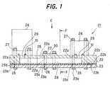
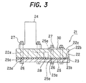
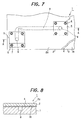
- FIG. 1 is a sectional view showing the configuration of a channel-incorporating pedestal according to Embodiment 1 of the present invention (a sectional view taken on line D-D of FIG. 2), FIG. 2 is a plan view taken in the direction of E in FIG. 1, and FIG. 3 is a sectional view taken on line F-F of FIG. 1.
- a channel-incorporating pedestal 21 comprises an upper plate 22, as a first plate, and a lower plate 23, as a second plate, joined together.
- An adhesive protective sheet 25 is interposed between the upper plate 22 and the lower plate 23.
- a groove 28 is formed in a joining surface 22b of the upper plate 22 by suitable means such as machining, injection molding, or die casting. Generally, a plurality of the grooves 28 are formed, have predetermined sectional areas (widths and depths), and are formed with suitable lengths in suitable directions.
- the lower plate 23 is joined to the upper plate 22 via the adhesive protective sheet 25 in such a manner as to cover the groove 28 formed in the upper plate 22. As a result, a channel for a fluid, which consists of the groove 28, is formed within the channel-incorporating pedestal 21.
- Communication holes 29 are formed in the upper plate 22, directly below the instruments 24 disposed on the upper plate 22, by suitable means such as machining, injection molding, or die casting.
- the groove 28 is brought into communication with the instruments 24 via these communication holes 29. That is, the groove 28 is incorporated, as the channel for a fluid, in the channel-incorporating pedestal 21.
- These built-in channels (grooves 28) have the function of piping connecting the instruments 24 together.
- the channel-incorporating pedestal 21 also functions as integrated piping.
- the sectional area of each groove 28 (built-in channel) is determined by the properties, flow velocity and pressure loss of the fluid flowing in each groove 28, and the length and direction of each groove 28 (built-in channel) are determined, for example, by the arrangement of the instruments 24.
- a clearance between the communication hole 29 and the instrument 24 is sealed with an O ring 31.
- the upper plate 22 comprises a nonmetallic material having corrosion resistance
- the lower plate 23 comprises a metallic material.
- the corrosion-resistant material are corrosion-free synthetic resins, such as fluoroplastic plates, for example, polytetrafluoroethylene (PTFE: Teflon).
- PTFE polytetrafluoroethylene
- the metallic material an aluminum plate and a steel plate can be named.
- the thickness of the lower plate 23 is a suitable thickness for required mechanical strength.
- the adhesive protective sheet 25 is a thermoplasticandcorrosion-resistantone.
- a publicly known, commercially available product can be used as the adhesive protective sheet 25.
- To be selected as the adhesive protective sheet 25 is a sheet-shaped product which is based on the same material as that of the upper plate 22, which has a suitable thickness, and which comprises, for example, a thermoplastic synthetic resin well compatible with and highly adhesive to a joining surface 23b of the lower plate 23.
- the adhesive protective sheet 25 has to have a lower melting point than those of the upper plate 22 and the lower plate 23. For example, if the material for the lower plate 23 is aluminum, and the material for the upper plate 22 is PTFE, then a material having a lower melting point than the melting point of PTFE (327°C) needs to be selected for the adhesive protective sheet 25.
- a method for producing the channel-incorporating pedestal 21 will be described.
- the adhesive protective sheet 25 is sandwiched (interposed) between the upper plate 22 and the lower plate 23 throughout the surfaces of the upper and lower plates 22 and 23.
- a suitable pressurizing means pressing means
- the adhesive protective sheet 25, together with the upper and lower plates 22 and 23, is pressurized (given pressure) under a suitable pressurizing force.
- the adhesive protective sheet 25, together with the upper and lower plates 22 and 23, is heated by a heating means, such as a baking furnace (heating furnace), to a suitable temperature at which the adhesive protective sheet 25 is melted and adhered.
- a heating means such as a baking furnace (heating furnace)
- the pressurizing force and the heating temperature differ according to the type of the adhesive protective sheet 25.
- the heating temperature is usually several hundred degrees centigrade.
- the upper plate 22 and the lower plate 23 are bonded together by the adhesive protective sheet 25.
- the upper and lower plates 22 and 23 are bonded by the adhesive protective sheet 25.
- the adhesive protective sheet 25 is fusion bonded to the joining surface 23b of the lower plate 23, coating or lining the joining surface 23b.
- the adhesive protective sheet 25 protects the relevant portion of the lower plate 23 from a corrosive fluid flowing in the groove 28.
- the instruments 24 are placed on the upper plate 22, and they are clamped by the bolts 26 and the nuts 27 for fixing, whereby sufficient strength of the bonding surfaces can be ensured. Furthermore, if it is necessary to enhance the bond strength between the upper and lower plates 22 and 23 because the fluid flowing through the groove 28 is at a high pressure, the upper and lower plates 22 and 23 and the adhesive protective sheet 25 may be clamped together by the bolts 26 and the nuts 27 via a suitable metal plate 30 disposed on the upper plate 22 for the purpose of reinforcement. In this case, it is vital that the bolt holes 22a, 23a and 25a evade the groove 28.
- the adhesive protective sheet 25 on the market will be illustrated. If, for example, the upper plate 22 is formed from PTFE, "RAP" (commercial name) of DAIKIN INDUSTRIES, which is an adhesive protective sheet comprising the same series of material as PTFE, was used, and bonded under pressure at a heating temperature of about 300°C. Satisfactory bond strength and anti-corrosion effect were obtained.
- RAP commercial name
- the channel-incorporating pedestal 21 of the present Embodiment 1 comprises the upper plate 22 and the lower plate 23 joined together, incorporates the groove 28, which is formed on the joining surface 22b of the upper plate 22, as the channel for the fluid, and brings the groove 28 into communication with the instruments 24, which are placed on the surface 22c of the upper plate 22, via the communication holes 29 formed in the upper plate 22.
- This channel-incorporating pedestal is characterized in that the upper plate 22 comprises the anticorrosive material, the lower plate 23 comprises the metallic material, and the upper plate 22 and the lower plate 23 are bonded together by the adhesive protective sheet 25 interposed between the upper plate 22 and the lower plate 23, the adhesive protective sheet 25 having a lower melting point than the melting points of the upper plate 22 and the lower plate 23, and being thermoplastic and anticorrosive.
- the method for producing the channel-incorporating pedestal 21 of the present Embodiment 1 is a method for producing a channel-incorporating pedestal, which comprises the upper plate 22 and the lower plate 23 joined together, incorporates the groove 28, formed on the joining surface 22b of the upper plate 22, as the channel for the fluid, and brings the groove 28 into communication with the instruments 24, placed on the surface 22c of the upper plate 22, via the communication holes 29 formed in the upper plate 22.
- This method is characterized by using the anticorrosive material as the upper plate 22, using the metallic material as the lower plate 23, and pressurizing and heating the upper plate 22 and the lower plate 23, with the adhesive protective sheet 25 being interposed between the upper plate 22 and the lower plate 23, the adhesive protective sheet 25 having a lower melting point than the melting points of the upper plate 22 and the lower plate 23, and being thermoplastic and anticorrosive, to melt the adhesive protective sheet 25, thereby bonding the upper plate 22 and the lower plate 23 together by the adhesive protective sheet 25.
- the upper plate 22 having the groove 28 and the communication holes 29 formed therein comprises the anticorrosive material
- the lower plate 23 comprising the metallic material is protected by the anticorrosive adhesive protective sheet 25.
- the upper plate 22 and the lower plate 23 have corrosion resistance, for example, to the corrosive fluid flowing in the groove 28.
- the lower plate 23 comprises the metallic material, so that the lower plate 23 can ensure the mechanical strength of the channel-incorporating pedestal 21. If further strength is needed, the further strength can be easily obtained simply by increasing the wall thickness of the lower plate 23. Moreover, the strength can be easily enhanced by clamping the upper plate 22 and the lower plate 23 by the bolt 26 and the nut 27 via the metal plate 30.
- the lower plate 23 has the simplest flat surface.
- a suitable pressurizing force and a suitable heating temperature to the adhesive protective sheet 25.
- satisfactory bonding force and anticorrosive performance can be ensured easily. Consequently, as compared with a conventional corrosion prevention measure such as aluminum oxide film coating, the channel-incorporating pedestal 21 with anticorrosive properties can be produced easily, and cost reduction can be achieved.
- a synthetic resin such as PTFE is used as the material for the upper plate 22, the groove 28 and the communication holes 29 can be formed easily by a method such as machining, injection molding, or die casting. Thus, further cost reduction can be achieved.
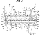
- FIG. 4 is a sectional view showing the configuration of a channel-incorporating pedestal according to Embodiment 2 of the present invention.
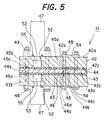
- FIG. 5 is a sectional view taken on line G-G of FIG. 4.
- a channel-incorpora ting pedestal 41 comprises an upper plate 42 as a first plate, an upper plate 43 as a third plate, and a lower plate 44 as a second plate joined together, with the lower plate 44 being interposed between the upper plate 42 and the upper plate 43. That is, the two upper plates 42 and 43 are stacked in opposed relation, with the lower plate 44 being interposed therebetween, to make up a multistage configuration.
- An adhesive protective sheet 45 is interposed between the upper plate 42 and the lower plate 44, and an adhesive protective sheet 46 is interposed between the upper plate 43 and the lower plate 44.
- Various instruments 47 such as components and devices constituting, for example, a fuel cell power generation system or a fluid control system, are placed on the surface 42a of the upper plate 42 and the surface 43a of the upper plate 43.
- the instruments 47 which are placed in vertical alignment, are fixed by clamping, integrally with the upper and lower plates 42, 43 and 44, by bolts 48 inserted through bolt holes 42b, 43b, 44a, 45a, 46a formed in the upper and lower plates 42, 43 and 44 and the adhesive protective sheets 45 and 46, and nuts 49 screwed to the bolts 48.
- the instruments 47 which are placed out of vertical alignment, are fixed by clamping, integrally with the upper and lower plates 42, 44 or the upper and lower plates 43, 44, by stud bolts 50 driven into the lower plate 44 and inserted through the bolt holes 45a, 42b or the bolt holes 46a, 43b, and nuts 51 screwed to the stud bolts 50. That is, the channel-incorporating pedestal 41 functions as a pedestal for mounting the instruments 47.
- Grooves 52 are formed in a joining surface 42c of the upper plate 42 and a joining surface 43c of the upper plate 43 by suitable means such as machining, injection molding, or die casting. Generally, a plurality of the grooves 52 are formed, have predetermined sectional areas (widths and depths), and are formed with suitable lengths in suitable directions.
- the lower plate 44 is joined to the upper plate 42 and the upper plate 43 via the adhesive protective sheets 45, 46 in such a manner as to cover the groove 52, as a first groove, formed in the upper plate 42, and the groove 52, as a second groove, formed in the upper plate 43.
- channels for fluids which consist of the grooves 52, are formed within the channel-incorporating pedestal 41.
- Communication holes 53 are formed in the upper plates 42, 43, directly below the instruments 47 disposed on the upper plates 42, 43, by suitable means such as machining, injection molding, or die casting.
- the groove 52 of the upper plate 42 is brought into communication with the instruments 47 on the upper plate 42 via the communication holes 53 of the upper plate 42.
- the groove 52 of the upper plate 43 is brought into communication with the instruments 47 on the upper plate 43 via the communication holes 53 of the upper plate 43. That is, the grooves 52 are incorporated, as the channels for fluids, in the channel-incorporating pedestal 41.
- These built-in channels (grooves 52) have the function of piping connecting the instruments 47 together.
- the channel-incorporating pedestal 41 also functions as integrated piping.
- each groove 52 built-in channel
- the sectional area of each groove 52 is determined by the properties, flow velocity and pressure loss of the fluid flowing in each groove 52, and the length and direction of each groove 52 (built-in channel) are determined, for example, by the arrangement of the instruments 47.
- a clearance between the communication hole 53 and the instrument 47 is sealed with an O ring 55.
- the upper plates 42, 43 each comprise a nonmetallic material having corrosion resistance
- the lower plate 44 comprises a metallic material.
- the corrosion-resistant material are corrosion-free synthetic resins, such as fluoroplastic plates, for example, polytetrafluoroethylene (PTFE: Teflon).
- PTFE polytetrafluoroethylene
- the metallic material an aluminum plate and a steel plate can be named.
- the thickness of the lower plate 44 is a suitable thickness for required mechanical strength.
- the adhesive protective sheets 45, 46 are thermoplastic and corrosion-resistant ones.
- a publicly known, commercially available product can be used as the adhesive protective sheets 45, 46.
- To be selected as the adhesive protective sheets 45, 46 is a sheet-shaped product which is based on the same material as that of the upper plates 42, 43, which has a suitable thickness, and which comprises, for example, a thermoplastic synthetic resin well compatible with and highly adhesive to the joining surfaces 44b, 44c of the lower plate 44.
- the adhesive protective sheets 45, 46 have to have a lower melting point than those of the upper plates 42, 43 and the lower plate 44.
- the material for the lower plate 44 is aluminum
- the material for the upper plates 42, 43 is PTFE
- a material having a lower melting point than the melting point of PTFE (327°C) needs to be selected for the adhesive protective sheets 45, 46.
- a method for producing the channel-incorporating pedestal 41 will be described.
- the adhesive protective sheet 45 is sandwiched (interposed) between the upper plate 42 and the lower plate 44 throughout the surfaces of the upper and lower plates 42 and 44.
- the adhesive protective sheet 46 is sandwiched (interposed) between the upper plate 43 and the lower plate 44 throughout the surfaces of the upper and lower plates 43 and 44.
- a suitable pressurizing means pressing means
- a clamping device not shown
- a heavy object is placed on the upper and lower plates 42, 43, 44.
- the adhesive protective sheets 45, 46, together with the upper and lower plates 42, 43, 44 are pressurized (given pressure) under a suitable pressurizing force.
- the adhesive protective sheets 45, 46, together with the upper and lower plates 42, 43, 44 are heated by a heating means, such as a baking furnace (heating furnace), to a suitable temperature at which the adhesive protective sheets 45, 46 are melted and adhered.
- a heating means such as a baking furnace (heating furnace)
- the pressurizing force and the heating temperature differ according to the type of the adhesive protective sheets 45, 46.
- the heating temperature is usually several hundred degrees centigrade.
- the upper plate 42 and the lower plate 44 are bonded together by the adhesive protective sheet 45, and the upper plate 43 and the lower plate 44 are bonded together by the adhesive protective sheet 46.
- the upper and lower plates 42 and 44 are bonded by the adhesive protective sheet 45.
- the adhesive protective sheet 45 is fusion bonded to the joining surface 44b of the lower plate 44, coating or lining the joining surface 44b.
- the adhesive protective sheet 45 protects the relevant portion of the lower plate 44 from a corrosive fluid flowing in the groove 52.
- the upper and lower plates 43 and 44 are bonded by the adhesive protective sheet 46.
- the adhesive protective sheet 46 is fusion bonded to the joining surface 44c of the lower plate 44, coating or lining the joining surface 44c.
- the adhesive protective sheet 46 protects the relevant portion of the lower plate 44 from a corrosive fluid flowing in the groove 52.
- the instruments 47 are placed on the upper plates 42, 43, and they are clamped by the bolts 48, 50 and the nuts 49, 51 for fixing, whereby sufficient strength of the bonding surfaces can be ensured. Furthermore, if it is necessary to enhance the bond strength between the upper plates 42, 43 and the lower plate 44 because the fluids flowing in the grooves 52 are set at a high pressure, the upper and lower plates 42, 43, 44 and the adhesive protective sheets 45, 46 may be clamped together by the bolts 48 and the nuts 49 via suitable metal plates 54 disposed on the upper plates 42, 43 for the purpose of reinforcement. In this case, it is vital that the bolt holes 42b, 43b, 45a, 46a evade the grooves 52.
- the channel-incorporating pedestal 41 of the present Embodiment 2 comprises the upper and lower plates 42, 43 and 44 joined together, with the lower plate 44 being interposed between the upper plates 42 and 43, incorporates the grooves 52, which are formed on the joining surfaces 42c, 43c of the upper plates 42, 43, as the channels for fluids, brings the groove 52 of the upper plate 42 into communication with the instruments 47, which are placed on the surface 42a of the upper plate 42, via the communication holes 53 formed in the upper plate 42, and brings the groove 52 of the upper plate 43 into communication with the instruments 47, which are placed on the surface 43a of the upper plate 43, via the communication holes 53 formed in the upper plate 43.
- This channel-incorporating pedestal is characterized in that the upper plates 42, 43 comprise the anticorrosive material, the lower plate 44 comprises the metallic material, the upper plate 42 and the lower plate 44 are bonded together by the adhesive protective sheet 45 interposed between the upper and lower plates 42 and 44, the adhesive protective sheet 45 having a lower melting point than the melting points of the upper and lower plates 42, 43, 44, and being thermoplastic and anticorrosive, and the upper plate 43 and the lower plate 44 are bonded together by the adhesive protective sheet 46 interposed between the upper and lower plates 43 and 44, the adhesive protective sheet 46 having a lower melting point than the melting points of the upper and lower plates 42, 43, 44, and being thermoplastic and anticorrosive.
- the method for producing the channel-incorporating pedestal 41 of the present Embodiment 2 is a method for producing a channel-incorporating pedestal, which comprises the upper and lower plates 42, 43, 44 joined together, with the lower plate 44 being interposed between the upper plates 42 and 43, incorporates the grooves 52, formed on the joining surfaces 42c, 43c of the upper plates 42, 43, as the channels for fluids, brings the groove 52 into communication with the instruments 47, placed on the surface 42a of the upper plate 42, via the communication holes 53 formed in the upper plate 42, and brings the groove 52 into communication with the instruments 47, placed on the surface 43a of the upper plate 43, via the communication holes 53 formed in the upper plate 43.
- This method is characterized by using the anticorrosive material as the upper plates 42, 43, using the metallic material as the lower plate 44, and pressurizing and heating the upper and lower plates 42, 43, 44, with the adhesive protective sheet 45 being interposed between the upper plate 42 and the lower plate 44, the adhesive protective sheet 45 having a lower melting point than the melting points of the upper and lower plates 42, 43, 44, and being thermoplastic and anticorrosive, and with the adhesive protective sheet 46 being interposed between the upper plate 43 and the lower plate 44, the adhesive protective sheet 46 having a lower melting point than the melting points of the upper and lower plates 42, 43, 44, and being thermoplastic and anticorrosive, to melt the adhesive protective sheets 45, 46, thereby bonding the upper plate 42 and the lower plate 44 together by the adhesive protective sheet 45, and bonding the upper plate 43 and the lower plate 44 together by the adhesive protective sheet 46.
- the upper plates 42, 43 having the grooves 52 and the communication holes 53 formed therein comprise the anticorrosive material
- the lower plate 44 comprising the metallic material is protected by the anticorrosive adhesive protective sheets 45, 46.
- the upper and lower plates 42, 43, 44 have corrosion resistance, for example, to the corrosive fluid flowing in the grooves 52.
- the lower plate 44 comprises the metallic material, so that the lower plate 44 can ensure the mechanical strength of the channel-incorporating pedestal 41. If further strength is needed, the further strength can be easily obtained simply by increasing the wall thickness of the lower plate 44.
- the strength can be easily enhanced by clamping the upper and lower plates 42, 43, 44 by the bolts 48 and the nuts 49 via the metal plate 54.
- the channel-incorporating pedestal 41 with anticorrosive properties can be produced easily, and cost reduction can be achieved.
- a synthetic resin such as PTFE is used as the material for the upper plate 42, the groove 52 and the communication holes 53 can be easily formed by a method such as machining, injection molding, or die casting. Thus, further cost reduction can be achieved.
- a multistage channel-incorporating pedestal which is compact and lightweight, can be produced.
- the present invention relates to a channel-incorporating pedestal, which is useful when applied in preventing the occurrence of cracks in weld lines surrounding the groove and the corrosion of the weld lines to maintain the sealing function of the weld lines.
Landscapes
- Engineering & Computer Science (AREA)
- Chemical & Material Sciences (AREA)
- General Chemical & Material Sciences (AREA)
- Life Sciences & Earth Sciences (AREA)
- Manufacturing & Machinery (AREA)
- Sustainable Development (AREA)
- Sustainable Energy (AREA)
- Chemical Kinetics & Catalysis (AREA)
- Electrochemistry (AREA)
- Physics & Mathematics (AREA)
- Fluid Mechanics (AREA)
- Mechanical Engineering (AREA)
- General Engineering & Computer Science (AREA)
- Composite Materials (AREA)
- Fuel Cell (AREA)
- Valve Housings (AREA)
- Standing Axle, Rod, Or Tube Structures Coupled By Welding, Adhesion, Or Deposition (AREA)
- Lining Or Joining Of Plastics Or The Like (AREA)
- Adhesives Or Adhesive Processes (AREA)
- Connection Of Plates (AREA)
Abstract
Description
- This invention relates to a channel-incorporating pedestal, and a method for producing it.
- A channel-incorporating pedestal is applied, for example, to various systems in various industrial fields, such as a stationary fuel cell power generation system for domestic use or a movable fuel cell power generation system for installation in a vehicle, and fluid control systems, e.g., air brake systems for trains. That is, the channel-incorporating pedestal is configured such that various instruments, such as components and devices constituting these systems, are mounted on the surface of the pedestal, built-in channels (grooves) are provided in place of complicated piping connecting these instruments (the built-in channels function as the piping), and further electrical wiring is also incorporated. The channel-incorporating pedestal, so configured, is put to practical uses as compact integrated units, such as stationary units including domestic fuel cell power generation units, and moving units including vehicle-installed fuel cell power generation units.
- Various proposals have been made for concrete configurational examples of the channel-incorporating pedestal. For example, those disclosed in Japanese Patent Application Laid-Open No. 2002-305010 can be named. A configurational example of a conventional channel-incorporating pedestal will be described hereinbelow with reference to FIGS. 6 to 8. FIG. 6 is a sectional view showing the configuration of the conventional channel-incorporating pedestal (a sectional view taken on line A-A of FIG. 7), FIG. 7 is a plan view taken in the direction of B in FIG. 6, and FIG. 8 is a sectional view taken on line C-C of FIG. 6.
- As shown in FIGS. 6, 7 and 8, a channel-incorporating
pedestal 1 comprises anupper plate 2 and alower plate 3 joined together by publicly known friction stir welding or asuitable binder 4.Various instruments 5, such as components and devices constituting, for example, a fuel cell power generation system or a fluid control system, which are suitably placed on the surface 2a of theupper plate 2, are fixed by clamping, integrally with the upper andlower plates bolts 6 inserted throughbolt holes 2b and 3a formed in the upper andlower plates nuts 7 screwed to thebolts 6. That is, the channel-incorporatingpedestal 1 functions as a pedestal for mounting theinstruments 5. - A
groove 8 is formed in a joiningsurface 3b of thelower plate 3. Generally, a plurality of thegrooves 8 are formed, have predetermined sectional areas, and are formed with suitable lengths in suitable directions. Theupper plate 2 is joined to thelower plate 3 in such a manner as to cover the groove 8 (put a lid on the groove 8) formed in thelower plate 3. As a result, a channel for a fluid, which consists of thegroove 8, is formed within the channel-incorporatingpedestal 1. -
Communication holes 9 are formed in theupper plate 2, and thegroove 8 are brought into communication with theinstruments 5 via thesecommunication holes 9. That is, thegroove 8 is incorporated, as the channel for a fluid, in the channel-incorporatingpedestal 1. These built-in channels (grooves 8) have the function of piping connecting theinstruments 5 together. In other words, the channel-incorporatingpedestal 1 also functions as integrated piping. The sectional area of each groove 8 (built-in channel) is determined by the properties, flow velocity and pressure loss of a fluid flowing in eachgroove 8, and the length and direction of each groove 8 (built-in channel) are determined, for example, by the arrangement of theinstruments 5. - As the material for the upper and
lower plates - There may be a case where the fluid flowing through the
groove 8 and thecommunication hole 9 is a corrosive fluid for the metallic material constituting the upper andlower plates groove 8 and thecommunication hole 9, which are in contact with the fluid, are coated with an aluminum oxide film (alumite), or are subjected to corrosion protection by polytetrafluoroethylene (PTFE: Teflon (registered trademark)) coating. Alternatively, theupper plate 2 and thelower plate 3, as a whole, are produced, for example, from corrosion-free synthetic resin. Such measures have so far dealt with possible corrosion. - However, the measures for corrosion protection involve a complicated manufacturing process, require a long time for completion, and need a great investment in production facilities, thus entailing high costs. Moreover, the production of the upper and
lower plates groove 8 is low, because the upper andlower plates - The present invention has been accomplished in light of the above-described circumstances. It is an object of the present invention to provide a channel-incorporating pedestal having corrosion resistance, which can be produced at a low cost, and which can ensure mechanical strength, and a method for producing the channel-incorporating pedestal.
- An aspect of the present invention is a channel-incorporating pedestal
comprisinga firstplate anda secondplate joined together,
incorporating a groove, which is formed on a joining surface of the first plate, as a channel for a fluid, and
bringing the groove into communication with an instrument, which is placed on a surface of the first plate, via a communication hole formed in the first plate, and
characterized in that the first plate comprises an anticorrosive material,
the second plate comprises a metallic material, and
the fist plate and the second plate are bonded together by an adhesive protective sheet interposed between the first plate and the second plate, the adhesive protective sheet having a lower melting point than melting points of the first plate and the second plate, and being thermoplastic and anticorrosive. - Another aspect of the present invention is a channel-incorporating pedestal
comprising a first plate, a second plate, and a third plate joined together, with the second plate being interposed between the first plate and the third plate,
incorporating a first groove, which is formed on a joining surface of the first plate, and a second groove, which is formed on a joining surface of the third plate, as channels for fluids,
bringing the first groove into communication with an instrument, which is placed on a surface of the first plate, via a first communication hole formed in the first plate, and
bringing the second groove into communication with an instrument, which is placed on a surface of the third plate, via a second communication hole formed in the third plate, and
characterized in that the first plate and the third plate comprise an anticorrosive material,
the second plate comprises a metallic material,
the fist plate and the second plate are bonded together by a first adhesive protective sheet interposedbetween the first plate and the second plate, the first adhesive protective sheet having a lower melting point than melting points of the first plate, the second plate, and the third plate, and being thermoplastic and anticorrosive, and
the third plate and the second plate are bonded together by a second adhesive protective sheet interposed between the third plate and the second plate, the second adhesive protective sheet having a lower melting point than melting points of the first plate, the second plate, and the third plate, and being thermoplastic and anticorrosive. - Still another aspect of the present invention is a method for producing a channel-incorporating pedestal,
the channel-incorporating pedestal
comprising a first plate and a second plate joined together,
incorporating a groove, which is formed on a joining surface of the first plate, as a channel for a fluid, and
bringing the groove into communication with an instrument, which is placed on a surface of the first plate, via a communication hole formed in the first plate,
the method characterized by
using a plate comprising an anticorrosive material as the first plate,
using a plate comprising a metallic material as the second plate, and
pressurizing and heating the fist plate and the second plate, with an adhesive protective sheet being interposed between the first plate and the second plate, the adhesive protective sheet having a lower melting point than melting points of the first plate and the second plate, and being thermoplastic and anticorrosive, to melt the adhesive protective sheet, thereby bonding the first plate and the second plate together by the adhesive protective sheet. - A further aspect of the present invention is a method for producing a channel-incorporating pedestal, the channel-incorporating pedestal
comprising a first plate, a second plate, and a third plate joined together, with the second plate being interposed between the first plate and the third plate,
incorporating a first groove, which is formed on a joining surface of the first plate, and a second groove, which is formed on a joining surface of the third plate, as channels for fluids,
bringing the first groove into communication with an instrument, which is placed on a surface of the first plate, via a first communication hole formed in the first plate, and
bringing the second groove into communication with an instrument, which is placed on a surface of the third plate, via a second communication hole formed in the third plate,
the method characterized by
using plates comprising an anticorrosive material as the first plate and the third plate,
using a plate comprising a metallic material as the second plate,
pressurizing and heating the fist plate, the second plate, and the third plate, with a first adhesive protective sheet being interposed between the first plate and the second plate, the first adhesive protective sheet having a lower melting point than melting points of the first plate, the second plate, and the third plate, and being thermoplastic and anticorrosive, and with a second adhesive protective sheet being interposed between the third plate and the second plate, the second adhesive protective sheet having a lower melting point than melting points of the first plate, the second plate, and the third plate, and being thermoplastic and anticorrosive, to melt the first adhesive protective sheet and the second adhesive protective sheet, thereby bonding the first plate and the second plate together by the first adhesive protective sheet, and bonding the third plate and the second plate together by the second adhesive protective sheet. - The present invention will become more fully understood from the detailed description given hereinbelow and the accompanying drawings which are given by way of illustration only, and thus are not limitative of the present invention, and wherein:
- FIG. 1 is a sectional view showing the configuration of a channel-incorporating pedestal according to
Embodiment 1 of the present invention (a sectional view taken on line D-D of FIG. 2); FIG. 2 is a plan view taken in the direction of E in FIG. 1; FIG. 3 is a sectional view taken on line F-F of FIG. 1; FIG. 4 is a sectional view showing the configuration of a channel-incorporating pedestal according toEmbodiment 2 of the present invention; FIG. 5 is a sectional view taken on line G-G of FIG. 4; FIG. 6 is a sectional view showing the configuration of a conventional channel-incorporating pedestal (a sectional view taken on line A-A of FIG. 7); FIG. 7 is a plan view taken in the direction of B in FIG. 6; and FIG. 8 is a sectional view taken on line C-C of FIG. 6. - Embodiments of the present invention will now be described in detail with reference to the accompanying drawings.
- FIG. 1 is a sectional view showing the configuration of a channel-incorporating pedestal according to
Embodiment 1 of the present invention (a sectional view taken on line D-D of FIG. 2), FIG. 2 is a plan view taken in the direction of E in FIG. 1, and FIG. 3 is a sectional view taken on line F-F of FIG. 1. - As shown in FIGS. 1, 2 and 3, a channel-incorporating
pedestal 21 comprises anupper plate 22, as a first plate, and alower plate 23, as a second plate, joined together. An adhesiveprotective sheet 25 is interposed between theupper plate 22 and thelower plate 23.Various instruments 24, such as components and devices constituting, for example, a fuel cell power generation system or a fluid control system, are placed on thesurface 22c of theupper plate 22. Theseinstruments 24 are fixed by clamping, integrally with the upper andlower plates bolts 26 inserted throughbolt holes lower plates protective sheet 25, andnuts 27 screwed to thebolts 26. That is, the channel-incorporatingpedestal 21 functions as a pedestal for mounting theinstruments 24. - A
groove 28 is formed in a joiningsurface 22b of theupper plate 22 by suitable means such as machining, injection molding, or die casting. Generally, a plurality of thegrooves 28 are formed, have predetermined sectional areas (widths and depths), and are formed with suitable lengths in suitable directions. Thelower plate 23 is joined to theupper plate 22 via the adhesiveprotective sheet 25 in such a manner as to cover thegroove 28 formed in theupper plate 22. As a result, a channel for a fluid, which consists of thegroove 28, is formed within the channel-incorporatingpedestal 21. - Communication holes 29 are formed in the
upper plate 22, directly below theinstruments 24 disposed on theupper plate 22, by suitable means such as machining, injection molding, or die casting. Thegroove 28 is brought into communication with theinstruments 24 via these communication holes 29. That is, thegroove 28 is incorporated, as the channel for a fluid, in the channel-incorporatingpedestal 21. These built-in channels (grooves 28) have the function of piping connecting theinstruments 24 together. Thus, the channel-incorporatingpedestal 21 also functions as integrated piping. The sectional area of each groove 28 (built-in channel) is determined by the properties, flow velocity and pressure loss of the fluid flowing in eachgroove 28, and the length and direction of each groove 28 (built-in channel) are determined, for example, by the arrangement of theinstruments 24. A clearance between thecommunication hole 29 and theinstrument 24 is sealed with anO ring 31. - The
upper plate 22 comprises a nonmetallic material having corrosion resistance, and thelower plate 23 comprises a metallic material. Examples of the corrosion-resistant material are corrosion-free synthetic resins, such as fluoroplastic plates, for example, polytetrafluoroethylene (PTFE: Teflon). As examples of the metallic material, an aluminum plate and a steel plate can be named. The thickness of thelower plate 23 is a suitable thickness for required mechanical strength. - The adhesive
protective sheet 25 is a thermoplasticandcorrosion-resistantone. A publicly known, commercially available product can be used as the adhesiveprotective sheet 25. To be selected as the adhesiveprotective sheet 25 is a sheet-shaped product which is based on the same material as that of theupper plate 22, which has a suitable thickness, and which comprises, for example, a thermoplastic synthetic resin well compatible with and highly adhesive to a joiningsurface 23b of thelower plate 23. Furthermore, the adhesiveprotective sheet 25 has to have a lower melting point than those of theupper plate 22 and thelower plate 23. For example, if the material for thelower plate 23 is aluminum, and the material for theupper plate 22 is PTFE, then a material having a lower melting point than the melting point of PTFE (327°C) needs to be selected for the adhesiveprotective sheet 25. - A method for producing the channel-incorporating
pedestal 21 will be described. First, the adhesiveprotective sheet 25 is sandwiched (interposed) between theupper plate 22 and thelower plate 23 throughout the surfaces of the upper andlower plates lower plates lower plates lower plates protective sheet 25, together with the upper andlower plates protective sheet 25, together with the upper andlower plates protective sheet 25 is melted and adhered. The pressurizing force and the heating temperature differ according to the type of the adhesiveprotective sheet 25. For example, the heating temperature is usually several hundred degrees centigrade. - As a result, the
upper plate 22 and thelower plate 23 are bonded together by the adhesiveprotective sheet 25. - Concretely, at the portion of joining between the upper and
lower plates protective sheet 25 contacts the joiningsurface 22b of theupper plate 22 and the joiningsurface 23b of the lower plate 23 (i.e., the portion other than the portion corresponding to thegroove 28 formed in the upper plate 22), the upper andlower plates protective sheet 25. In the non-joining portion of the upper andlower plates groove 28 formed in theupper plate 22, the adhesiveprotective sheet 25 is fusion bonded to the joiningsurface 23b of thelower plate 23, coating or lining the joiningsurface 23b. Thus, the adhesiveprotective sheet 25 protects the relevant portion of thelower plate 23 from a corrosive fluid flowing in thegroove 28. - Then, the
instruments 24 are placed on theupper plate 22, and they are clamped by thebolts 26 and thenuts 27 for fixing, whereby sufficient strength of the bonding surfaces can be ensured. Furthermore, if it is necessary to enhance the bond strength between the upper andlower plates groove 28 is at a high pressure, the upper andlower plates protective sheet 25 may be clamped together by thebolts 26 and thenuts 27 via asuitable metal plate 30 disposed on theupper plate 22 for the purpose of reinforcement. In this case, it is vital that thebolt holes groove 28. - The adhesive
protective sheet 25 on the market will be illustrated. If, for example, theupper plate 22 is formed from PTFE, "RAP" (commercial name) of DAIKIN INDUSTRIES, which is an adhesive protective sheet comprising the same series of material as PTFE, was used, and bonded under pressure at a heating temperature of about 300°C. Satisfactory bond strength and anti-corrosion effect were obtained. - As described above, the channel-incorporating
pedestal 21 of thepresent Embodiment 1 comprises theupper plate 22 and thelower plate 23 joined together, incorporates thegroove 28, which is formed on the joiningsurface 22b of theupper plate 22, as the channel for the fluid, and brings thegroove 28 into communication with theinstruments 24, which are placed on thesurface 22c of theupper plate 22, via the communication holes 29 formed in theupper plate 22. This channel-incorporating pedestal is characterized in that theupper plate 22 comprises the anticorrosive material, thelower plate 23 comprises the metallic material, and theupper plate 22 and thelower plate 23 are bonded together by the adhesiveprotective sheet 25 interposed between theupper plate 22 and thelower plate 23, the adhesiveprotective sheet 25 having a lower melting point than the melting points of theupper plate 22 and thelower plate 23, and being thermoplastic and anticorrosive. - The method for producing the channel-incorporating
pedestal 21 of thepresent Embodiment 1 is a method for producing a channel-incorporating pedestal, which comprises theupper plate 22 and thelower plate 23 joined together, incorporates thegroove 28, formed on the joiningsurface 22b of theupper plate 22, as the channel for the fluid, and brings thegroove 28 into communication with theinstruments 24, placed on thesurface 22c of theupper plate 22, via the communication holes 29 formed in theupper plate 22. This method is characterized by using the anticorrosive material as theupper plate 22, using the metallic material as thelower plate 23, and pressurizing and heating theupper plate 22 and thelower plate 23, with the adhesiveprotective sheet 25 being interposed between theupper plate 22 and thelower plate 23, the adhesiveprotective sheet 25 having a lower melting point than the melting points of theupper plate 22 and thelower plate 23, and being thermoplastic and anticorrosive, to melt the adhesiveprotective sheet 25, thereby bonding theupper plate 22 and thelower plate 23 together by the adhesiveprotective sheet 25. - According to the
present Embodiment 1, as described above, theupper plate 22 having thegroove 28 and the communication holes 29 formed therein comprises the anticorrosive material, and thelower plate 23 comprising the metallic material is protected by the anticorrosive adhesiveprotective sheet 25. Thus, theupper plate 22 and thelower plate 23 have corrosion resistance, for example, to the corrosive fluid flowing in thegroove 28. Furthermore, thelower plate 23 comprises the metallic material, so that thelower plate 23 can ensure the mechanical strength of the channel-incorporatingpedestal 21. If further strength is needed, the further strength can be easily obtained simply by increasing the wall thickness of thelower plate 23. Moreover, the strength can be easily enhanced by clamping theupper plate 22 and thelower plate 23 by thebolt 26 and thenut 27 via themetal plate 30. - Besides, corrosion prevention can be easily performed simply by bonding the upper and
lower plates protective sheet 25. For example, thelower plate 23 has the simplest flat surface. Thus, merely by applying a suitable pressurizing force and a suitable heating temperature to the adhesiveprotective sheet 25, satisfactory bonding force and anticorrosive performance can be ensured easily. Consequently, as compared with a conventional corrosion prevention measure such as aluminum oxide film coating, the channel-incorporatingpedestal 21 with anticorrosive properties can be produced easily, and cost reduction can be achieved. If a synthetic resin such as PTFE is used as the material for theupper plate 22, thegroove 28 and the communication holes 29 can be formed easily by a method such as machining, injection molding, or die casting. Thus, further cost reduction can be achieved. - FIG. 4 is a sectional view showing the configuration of a channel-incorporating pedestal according to
Embodiment 2 of the present invention. FIG. 5 is a sectional view taken on line G-G of FIG. 4. - As shown in FIGS. 4 and 5, a channel-
incorpora ting pedestal 41 comprises anupper plate 42 as a first plate, anupper plate 43 as a third plate, and alower plate 44 as a second plate joined together, with thelower plate 44 being interposed between theupper plate 42 and theupper plate 43. That is, the twoupper plates lower plate 44 being interposed therebetween, to make up a multistage configuration. An adhesiveprotective sheet 45 is interposed between theupper plate 42 and thelower plate 44, and an adhesiveprotective sheet 46 is interposed between theupper plate 43 and thelower plate 44. -
Various instruments 47, such as components and devices constituting, for example, a fuel cell power generation system or a fluid control system, are placed on thesurface 42a of theupper plate 42 and thesurface 43a of theupper plate 43. Theinstruments 47, which are placed in vertical alignment, are fixed by clamping, integrally with the upper andlower plates bolts 48 inserted throughbolt holes lower plates protective sheets nuts 49 screwed to thebolts 48. Theinstruments 47, which are placed out of vertical alignment, are fixed by clamping, integrally with the upper andlower plates lower plates stud bolts 50 driven into thelower plate 44 and inserted through thebolt holes bolt holes nuts 51 screwed to thestud bolts 50. That is, the channel-incorporatingpedestal 41 functions as a pedestal for mounting theinstruments 47. -
Grooves 52 are formed in a joiningsurface 42c of theupper plate 42 and a joiningsurface 43c of theupper plate 43 by suitable means such as machining, injection molding, or die casting. Generally, a plurality of thegrooves 52 are formed, have predetermined sectional areas (widths and depths), and are formed with suitable lengths in suitable directions. Thelower plate 44 is joined to theupper plate 42 and theupper plate 43 via the adhesiveprotective sheets groove 52, as a first groove, formed in theupper plate 42, and thegroove 52, as a second groove, formed in theupper plate 43. As a result, channels for fluids, which consist of thegrooves 52, are formed within the channel-incorporatingpedestal 41. - Communication holes 53 are formed in the
upper plates instruments 47 disposed on theupper plates groove 52 of theupper plate 42 is brought into communication with theinstruments 47 on theupper plate 42 via the communication holes 53 of theupper plate 42. Thegroove 52 of theupper plate 43 is brought into communication with theinstruments 47 on theupper plate 43 via the communication holes 53 of theupper plate 43. That is, thegrooves 52 are incorporated, as the channels for fluids, in the channel-incorporatingpedestal 41. These built-in channels (grooves 52) have the function of piping connecting theinstruments 47 together. Thus, the channel-incorporatingpedestal 41 also functions as integrated piping. The sectional area of each groove 52 (built-in channel) is determined by the properties, flow velocity and pressure loss of the fluid flowing in eachgroove 52, and the length and direction of each groove 52 (built-in channel) are determined, for example, by the arrangement of theinstruments 47. A clearance between thecommunication hole 53 and theinstrument 47 is sealed with anO ring 55. - The
upper plates lower plate 44 comprises a metallic material. Examples of the corrosion-resistant material are corrosion-free synthetic resins, such as fluoroplastic plates, for example, polytetrafluoroethylene (PTFE: Teflon). As examples of the metallic material, an aluminum plate and a steel plate can be named. The thickness of thelower plate 44 is a suitable thickness for required mechanical strength. - The adhesive
protective sheets protective sheets protective sheets upper plates surfaces lower plate 44. Furthermore, the adhesiveprotective sheets upper plates lower plate 44. For example, if the material for thelower plate 44 is aluminum, and the material for theupper plates protective sheets - A method for producing the channel-incorporating
pedestal 41 will be described. First, the adhesiveprotective sheet 45 is sandwiched (interposed) between theupper plate 42 and thelower plate 44 throughout the surfaces of the upper andlower plates protective sheet 46 is sandwiched (interposed) between theupper plate 43 and thelower plate 44 throughout the surfaces of the upper andlower plates lower plates lower plates lower plates protective sheets lower plates protective sheets lower plates protective sheets protective sheets - As a result, the
upper plate 42 and thelower plate 44 are bonded together by the adhesiveprotective sheet 45, and theupper plate 43 and thelower plate 44 are bonded together by the adhesiveprotective sheet 46. - Concretely, at the portion of joining between the upper and
lower plates protective sheet 45 contacts the joiningsurface 42c of theupper plate 42 and the joiningsurface 44b of the lower plate 44 (i.e., the portion other than the portion corresponding to thegroove 52 formed in the upper plate 42), the upper andlower plates protective sheet 45. In the non-joining portion of the upper andlower plates groove 52 formed in theupper plate 42, the adhesiveprotective sheet 45 is fusion bonded to the joiningsurface 44b of thelower plate 44, coating or lining the joiningsurface 44b. Thus, the adhesiveprotective sheet 45 protects the relevant portion of thelower plate 44 from a corrosive fluid flowing in thegroove 52. - Similarly, at the portion of joining between the upper and
lower plates protective sheet 46 contacts the joiningsurface 43c of theupper plate 43 and the joiningsurface 44c of the lower plate 44 (i.e., the portion other than the portion corresponding to thegroove 52 formed in the upper plate 43), the upper andlower plates protective sheet 46. In the non-joining portion of the upper andlower plates groove 52 formed in theupper plate 43, the adhesiveprotective sheet 46 is fusion bonded to the joiningsurface 44c of thelower plate 44, coating or lining the joiningsurface 44c. Thus, the adhesiveprotective sheet 46 protects the relevant portion of thelower plate 44 from a corrosive fluid flowing in thegroove 52. - Then, the
instruments 47 are placed on theupper plates bolts upper plates lower plate 44 because the fluids flowing in thegrooves 52 are set at a high pressure, the upper andlower plates protective sheets bolts 48 and thenuts 49 viasuitable metal plates 54 disposed on theupper plates grooves 52. - As described above, the channel-incorporating
pedestal 41 of thepresent Embodiment 2 comprises the upper andlower plates lower plate 44 being interposed between theupper plates grooves 52, which are formed on the joiningsurfaces upper plates groove 52 of theupper plate 42 into communication with theinstruments 47, which are placed on thesurface 42a of theupper plate 42, via the communication holes 53 formed in theupper plate 42, and brings thegroove 52 of theupper plate 43 into communication with theinstruments 47, which are placed on thesurface 43a of theupper plate 43, via the communication holes 53 formed in theupper plate 43. This channel-incorporating pedestal is characterized in that theupper plates lower plate 44 comprises the metallic material, theupper plate 42 and thelower plate 44 are bonded together by the adhesiveprotective sheet 45 interposed between the upper andlower plates protective sheet 45 having a lower melting point than the melting points of the upper andlower plates upper plate 43 and thelower plate 44 are bonded together by the adhesiveprotective sheet 46 interposed between the upper andlower plates protective sheet 46 having a lower melting point than the melting points of the upper andlower plates - The method for producing the channel-incorporating
pedestal 41 of thepresent Embodiment 2 is a method for producing a channel-incorporating pedestal, which comprises the upper andlower plates lower plate 44 being interposed between theupper plates grooves 52, formed on the joiningsurfaces upper plates groove 52 into communication with theinstruments 47, placed on thesurface 42a of theupper plate 42, via the communication holes 53 formed in theupper plate 42, and brings thegroove 52 into communication with theinstruments 47, placed on thesurface 43a of theupper plate 43, via the communication holes 53 formed in theupper plate 43. This method is characterized by using the anticorrosive material as theupper plates lower plate 44, and pressurizing and heating the upper andlower plates protective sheet 45 being interposed between theupper plate 42 and thelower plate 44, the adhesiveprotective sheet 45 having a lower melting point than the melting points of the upper andlower plates protective sheet 46 being interposed between theupper plate 43 and thelower plate 44, the adhesiveprotective sheet 46 having a lower melting point than the melting points of the upper andlower plates protective sheets upper plate 42 and thelower plate 44 together by the adhesiveprotective sheet 45, and bonding theupper plate 43 and thelower plate 44 together by the adhesiveprotective sheet 46. - According to the
present Embodiment 2 , theupper plates grooves 52 and the communication holes 53 formed therein comprise the anticorrosive material, and thelower plate 44 comprising the metallic material is protected by the anticorrosive adhesiveprotective sheets lower plates grooves 52. Furthermore, thelower plate 44 comprises the metallic material, so that thelower plate 44 can ensure the mechanical strength of the channel-incorporatingpedestal 41. If further strength is needed, the further strength can be easily obtained simply by increasing the wall thickness of thelower plate 44. Moreover, the strength can be easily enhanced by clamping the upper andlower plates bolts 48 and thenuts 49 via themetal plate 54. - Besides, corrosion prevention can be easily performed simply by bonding the upper and
lower plates protective sheets lower plate 44 has the simplest flat surface. Thus, merely by applying a suitable pressurizing force and a suitable heating temperature to the adhesiveprotective sheets pedestal 41 with anticorrosive properties can be produced easily, and cost reduction can be achieved. If a synthetic resin such as PTFE is used as the material for theupper plate 42, thegroove 52 and the communication holes 53 can be easily formed by a method such as machining, injection molding, or die casting. Thus, further cost reduction can be achieved. Furthermore, a multistage channel-incorporating pedestal, which is compact and lightweight, can be produced. - As described above, the present invention relates to a channel-incorporating pedestal, which is useful when applied in preventing the occurrence of cracks in weld lines surrounding the groove and the corrosion of the weld lines to maintain the sealing function of the weld lines.
- The invention thus described, it will be obvious that the same may be varied in many ways. Such variations are not to be regarded as a departure from the spirit and scope of the invention, and all such modifications as would be obvious to one skilled in the art are intended to be included within the scope of the following claims.
Claims (4)
- A channel-incorporating pedestal (21)
comprising a first plate (22) and a second plate (23) joined together,
incorporating a groove (28), which is formed on a joining surface (22b) of said first plate (22), as a channel for a fluid, and
bringing said groove (28) into communication with an instrument (24), which is placed on a surface (22c) of said first plate (22), via a communication hole (29) formed in said first plate (22), and
characterized in that said first plate (22) comprises an anticorrosive material,
said second plate (23) comprises a metallic material, and
said fist plate (22) and said second plate (23) are bonded together by an adhesive protective sheet (25) interposed between said first plate (22) and said second plate (23), said adhesive protective sheet (25) having a lower melting point than melting points of said first plate (22) and said second plate (23), and being thermoplastic and anticorrosive. - A channel-incorporating pedestal (41)
comprising a first plate (42), a second plate (44), and a third plate (43) joined together, with said second plate (44) being interposed between said first plate (42) and said third plate (43),
incorporating a first groove (52), which is formed on a joining surface (42c) of said first plate (42), and a second groove (52), which is formed on a joining surface (43c) of said third plate (43), as channels for fluids,
bringing said first groove (52) into communication with an instrument (47), which is placed on a surface (42a) of said first plate (42), via a first communication hole (53) formedinsaidfirstplate (42), and
bringing said second groove (52) into communication with an instrument (47), which is placed on a surface (43a) of said third plate (43), via a second communication hole (53) formedinsaidthirdplate (43), and
characterized in that said first plate (42) and said third plate (43) comprise an anticorrosive material,
said second plate (44) comprises a metallic material,
said fist plate (42) and said second plate (44) are bonded together by a first adhesive protective sheet (45) interposed between said first plate (42) and said second plate (44), said first adhesive protective sheet (45) having a lower melting point than melting points of said first plate (42), said second plate (44), and said third plate (43), and being thermoplastic and anticorrosive, and
said third plate (43) and said second plate (44) are bonded together by a second adhesive protective sheet (46) interposed between said third plate (43) and said second plate (44), said second adhesive protective sheet (46) having a lower melting point than melting points of said first plate (42), said second plate (44), and said third plate (43), and being thermoplastic and anticorrosive. - A method for producing a channel-incorporating pedestal (21),
said channel-incorporating pedestal (21)
comprising a first plate (22) and a second plate (23) joined together,
incorporating a groove (28), which is formed on a joining surface (22b) of said first plate (22), as a channel for a fluid, and
bringing said groove (28) into communication with an instrument (24), which is placed on a surface (22c) of said first plate (22), via a communication hole (29) formed in said first plate (22),
said method being characterized by
using a plate comprising an anticorrosive material as said first plate (22),
using a plate comprising a metallic material as said second plate (23), and
pressurizing and heating said fist plate (22) and said second plate (23), with an adhesive protective sheet (25) being interposed between said first plate (22) and said second plate (23), said adhesive protective sheet (25) having a lower melting point than melting points of said first plate (22) and said second plate (23), and being thermoplastic and anticorrosive, to melt said adhesive protective sheet (25), thereby bonding said first plate (22) and said second plate (23) together by said adhesive protective sheet (25). - A method for producing a channel-incorporating pedestal (41), said channel-incorporating pedestal (41)
comprising a first plate (42), a second plate (44), and a third plate (43) joined together, with said second plate (44) being interposed between said first plate (42) and said third plate (43),
incorporating a first groove (52), which is formed on a joining surface (42c) of said first plate (42), and a second groove (52), which is formed on a joining surface (43c) of said third plate (43), as channels for fluids,
bringing said first groove (52) into communication with an instrument (47), which is placed on a surface (42a) of said first plate (42), via a first communication hole (53) formedinsaidfirstplate (42), and
bringing said second groove (52) into communication with an instrument (47), which is placed on a surface (43a) of said third plate (43), via a second communicationhole (53) formed in said thirdplate (43),
said method being characterized by
using plates comprising an anticorrosive material as said first plate (42) and said third plate (43),
using a plate comprising a metallic material as said second plate (44),
pressurizing and heating said fist plate (42), said second plate (44), and said third plate (43), with a first adhesive protective sheet (45) being interposed between said first plate (42) and said second plate (44), said first adhesive protective sheet (45) having a lower melting point than melting points of said first plate (42), said second plate (44), and said third plate (43), and being thermoplastic and anticorrosive, and with a second adhesive protective sheet (46) being interposed between said third plate (43) andsaidsecond plate (44), said second adhesive protective sheet (46) having a lower melting point than melting points of said first plate (42), said second plate (44), and said third plate (43), and being thermoplastic and anticorrosive, to melt said first adhesive protective sheet (45) and said second adhesive protective sheet (46), thereby bonding said first plate (42) and said second plate (44) together by said first adhesive protective sheet (45), and bonding said third plate (43) and said second plate (44) together by said second adhesive protective sheet (46).
Applications Claiming Priority (1)
| Application Number | Priority Date | Filing Date | Title |
|---|---|---|---|
| JP2004212904A JP2006032264A (en) | 2004-07-21 | 2004-07-21 | Channel built-in base and method for manufacturing the same |
Publications (3)
| Publication Number | Publication Date |
|---|---|
| EP1624517A2 true EP1624517A2 (en) | 2006-02-08 |
| EP1624517A3 EP1624517A3 (en) | 2006-05-17 |
| EP1624517B1 EP1624517B1 (en) | 2009-04-29 |
Family
ID=35295511
Family Applications (1)
| Application Number | Title | Priority Date | Filing Date |
|---|---|---|---|
| EP20050105979 Expired - Lifetime EP1624517B1 (en) | 2004-07-21 | 2005-06-30 | Channel-incorporating pedestal and method for producing the same |
Country Status (7)
| Country | Link |
|---|---|
| US (1) | US20060019144A1 (en) |
| EP (1) | EP1624517B1 (en) |
| JP (1) | JP2006032264A (en) |
| KR (1) | KR100651319B1 (en) |
| CN (1) | CN1724922A (en) |
| DE (1) | DE602005014177D1 (en) |
| NO (1) | NO20053554L (en) |
Families Citing this family (10)
| Publication number | Priority date | Publication date | Assignee | Title |
|---|---|---|---|---|
| CN104382691B (en) | 2007-11-21 | 2018-08-31 | 史密夫及内修公开有限公司 | wound dressing |
| GB0723855D0 (en) | 2007-12-06 | 2008-01-16 | Smith & Nephew | Apparatus and method for wound volume measurement |
| DE102008001990A1 (en) * | 2008-05-27 | 2009-12-03 | Robert Bosch Gmbh | Electric parking brake |
| GB201015656D0 (en) | 2010-09-20 | 2010-10-27 | Smith & Nephew | Pressure control apparatus |
| US9067003B2 (en) | 2011-05-26 | 2015-06-30 | Kalypto Medical, Inc. | Method for providing negative pressure to a negative pressure wound therapy bandage |
| US9084845B2 (en) | 2011-11-02 | 2015-07-21 | Smith & Nephew Plc | Reduced pressure therapy apparatuses and methods of using same |
| EP2825220B2 (en) | 2012-03-12 | 2021-03-03 | Smith & Nephew PLC | Reduced pressure apparatus and methods |
| CN104507513B (en) | 2012-03-20 | 2017-04-12 | 史密夫及内修公开有限公司 | Controlling operation of a reduced pressure therapy system based on dynamic duty cycle threshold determination |
| US9427505B2 (en) | 2012-05-15 | 2016-08-30 | Smith & Nephew Plc | Negative pressure wound therapy apparatus |
| US10737002B2 (en) | 2014-12-22 | 2020-08-11 | Smith & Nephew Plc | Pressure sampling systems and methods for negative pressure wound therapy |
Family Cites Families (7)
| Publication number | Priority date | Publication date | Assignee | Title |
|---|---|---|---|---|
| US4110140A (en) * | 1976-12-15 | 1978-08-29 | Johnson Controls, Inc. | Method of making fluid system circuit board |
| US5558955A (en) * | 1994-10-07 | 1996-09-24 | International Fuel Cells Corporation | Cathode reactant flow field component for a fuel cell stack |
| KR100228529B1 (en) * | 1996-12-20 | 1999-11-01 | 윤종용 | Level shifter for semiconductor memory |
| JP3731322B2 (en) * | 1997-11-04 | 2006-01-05 | ソニー株式会社 | Level shift circuit |
| US7017792B2 (en) * | 2001-02-02 | 2006-03-28 | Mitsubishi Heavy Industries, Ltd. | Integrated piping plate, machining method for same, machining apparatus for same, and machining equipment for same |
| JP3930271B2 (en) * | 2001-02-02 | 2007-06-13 | 三菱重工業株式会社 | Logic plate |
| US6907904B2 (en) * | 2003-03-03 | 2005-06-21 | Redwood Microsystems, Inc. | Fluid delivery system and mounting panel therefor |
-
2004
- 2004-07-21 JP JP2004212904A patent/JP2006032264A/en not_active Withdrawn
-
2005
- 2005-06-30 DE DE200560014177 patent/DE602005014177D1/en not_active Expired - Lifetime
- 2005-06-30 EP EP20050105979 patent/EP1624517B1/en not_active Expired - Lifetime
- 2005-07-06 US US11/174,479 patent/US20060019144A1/en not_active Abandoned
- 2005-07-12 CN CNA2005100833618A patent/CN1724922A/en active Pending
- 2005-07-20 KR KR1020050065873A patent/KR100651319B1/en not_active Expired - Fee Related
- 2005-07-20 NO NO20053554A patent/NO20053554L/en not_active Application Discontinuation
Also Published As
| Publication number | Publication date |
|---|---|
| DE602005014177D1 (en) | 2009-06-10 |
| NO20053554L (en) | 2006-01-23 |
| NO20053554D0 (en) | 2005-07-20 |
| KR20060053953A (en) | 2006-05-22 |
| CN1724922A (en) | 2006-01-25 |
| EP1624517A3 (en) | 2006-05-17 |
| US20060019144A1 (en) | 2006-01-26 |
| JP2006032264A (en) | 2006-02-02 |
| KR100651319B1 (en) | 2006-11-29 |
| EP1624517B1 (en) | 2009-04-29 |
Similar Documents
| Publication | Publication Date | Title |
|---|---|---|
| EP1624517B1 (en) | Channel-incorporating pedestal and method for producing the same | |
| CN102159859A (en) | Comby two-sided overlain gasket for sealing of dismountable flanged joints | |
| US20160282059A1 (en) | Layered heat transfer device and method for producing a layered heat transfer device | |
| US7004198B1 (en) | Micro-fluidic interconnect | |
| US9627294B2 (en) | Semiconductor device and method of manufacturing the same | |
| US6886629B2 (en) | Plate heat exchanger | |
| US4184785A (en) | Axially bolted flange joint | |
| JP4208957B2 (en) | gasket | |
| US20170219148A1 (en) | Flow passage structure | |
| WO2009064490A2 (en) | Microchannel structures having bonded layers including height control features | |
| CN104813134A (en) | Plate heat exchanger having sealed construction | |
| Paul et al. | Understanding limits on fin aspect ratios in counterflow microchannel arrays produced by diffusion bonding | |
| US6398264B1 (en) | Thermally activated joining apparatus | |
| JP2005136117A (en) | Heat protecting device of electronic part having adhering function | |
| CN119866571A (en) | Cooling bottom member and method for manufacturing cooling bottom member | |
| KR20090064540A (en) | Gasket | |
| Thakare et al. | A review on design and analysis of adhesive bonded joint by finite element analysis | |
| WO2007049339A1 (en) | Gasket | |
| CN102966778A (en) | Valve housing for control valve, and method of manufacturing the same | |
| CN214466713U (en) | Composite pipeline | |
| JP2006032265A (en) | Pedestal with built-in passage | |
| JP6566138B2 (en) | Laminated metal plate assembly | |
| EP4464971A1 (en) | Heat exchanger | |
| JP2004316663A (en) | Logic plate | |
| KR20240029241A (en) | A conjugate body of different metals |
Legal Events
| Date | Code | Title | Description |
|---|---|---|---|
| PUAI | Public reference made under article 153(3) epc to a published international application that has entered the european phase |
Free format text: ORIGINAL CODE: 0009012 |
|
| 17P | Request for examination filed |
Effective date: 20051026 |
|
| AK | Designated contracting states |
Kind code of ref document: A2 Designated state(s): AT BE BG CH CY CZ DE DK EE ES FI FR GB GR HU IE IS IT LI LT LU MC NL PL PT RO SE SI SK TR |
|
| AX | Request for extension of the european patent |
Extension state: AL BA HR LV MK YU |
|
| PUAL | Search report despatched |
Free format text: ORIGINAL CODE: 0009013 |
|
| AK | Designated contracting states |
Kind code of ref document: A3 Designated state(s): AT BE BG CH CY CZ DE DK EE ES FI FR GB GR HU IE IS IT LI LT LU MC NL PL PT RO SE SI SK TR |
|
| AX | Request for extension of the european patent |
Extension state: AL BA HR LV MK YU |
|
| AKX | Designation fees paid |
Designated state(s): DE FR GB IT NL |
|
| 17Q | First examination report despatched |
Effective date: 20070904 |
|
| GRAC | Information related to communication of intention to grant a patent modified |
Free format text: ORIGINAL CODE: EPIDOSCIGR1 |
|
| GRAP | Despatch of communication of intention to grant a patent |
Free format text: ORIGINAL CODE: EPIDOSNIGR1 |
|
| GRAS | Grant fee paid |
Free format text: ORIGINAL CODE: EPIDOSNIGR3 |
|
| GRAA | (expected) grant |
Free format text: ORIGINAL CODE: 0009210 |
|
| AK | Designated contracting states |
Kind code of ref document: B1 Designated state(s): DE FR GB IT NL |
|
| REG | Reference to a national code |
Ref country code: GB Ref legal event code: FG4D |
|
| REF | Corresponds to: |
Ref document number: 602005014177 Country of ref document: DE Date of ref document: 20090610 Kind code of ref document: P |
|
| PLBE | No opposition filed within time limit |
Free format text: ORIGINAL CODE: 0009261 |
|
| STAA | Information on the status of an ep patent application or granted ep patent |
Free format text: STATUS: NO OPPOSITION FILED WITHIN TIME LIMIT |
|
| 26N | No opposition filed |
Effective date: 20100201 |
|
| PG25 | Lapsed in a contracting state [announced via postgrant information from national office to epo] |
Ref country code: IT Free format text: LAPSE BECAUSE OF NON-PAYMENT OF DUE FEES Effective date: 20090630 |
|
| PGRI | Patent reinstated in contracting state [announced from national office to epo] |
Ref country code: IT Effective date: 20110616 |
|
| PGFP | Annual fee paid to national office [announced via postgrant information from national office to epo] |
Ref country code: DE Payment date: 20120627 Year of fee payment: 8 Ref country code: NL Payment date: 20120626 Year of fee payment: 8 |
|
| PGFP | Annual fee paid to national office [announced via postgrant information from national office to epo] |
Ref country code: FR Payment date: 20120619 Year of fee payment: 8 Ref country code: GB Payment date: 20120627 Year of fee payment: 8 |
|
| PGFP | Annual fee paid to national office [announced via postgrant information from national office to epo] |
Ref country code: IT Payment date: 20120621 Year of fee payment: 8 |
|
| REG | Reference to a national code |
Ref country code: NL Ref legal event code: V1 Effective date: 20140101 |
|
| GBPC | Gb: european patent ceased through non-payment of renewal fee |
Effective date: 20130630 |
|
| REG | Reference to a national code |
Ref country code: DE Ref legal event code: R119 Ref document number: 602005014177 Country of ref document: DE Effective date: 20140101 |
|
| REG | Reference to a national code |
Ref country code: FR Ref legal event code: ST Effective date: 20140228 |
|
| PG25 | Lapsed in a contracting state [announced via postgrant information from national office to epo] |
Ref country code: DE Free format text: LAPSE BECAUSE OF NON-PAYMENT OF DUE FEES Effective date: 20140101 Ref country code: NL Free format text: LAPSE BECAUSE OF NON-PAYMENT OF DUE FEES Effective date: 20140101 Ref country code: GB Free format text: LAPSE BECAUSE OF NON-PAYMENT OF DUE FEES Effective date: 20130630 |
|
| PG25 | Lapsed in a contracting state [announced via postgrant information from national office to epo] |
Ref country code: IT Free format text: LAPSE BECAUSE OF NON-PAYMENT OF DUE FEES Effective date: 20130630 Ref country code: FR Free format text: LAPSE BECAUSE OF NON-PAYMENT OF DUE FEES Effective date: 20130701 |