EP1624455A2 - Disc apparatus - Google Patents
Disc apparatus Download PDFInfo
- Publication number
- EP1624455A2 EP1624455A2 EP05016329A EP05016329A EP1624455A2 EP 1624455 A2 EP1624455 A2 EP 1624455A2 EP 05016329 A EP05016329 A EP 05016329A EP 05016329 A EP05016329 A EP 05016329A EP 1624455 A2 EP1624455 A2 EP 1624455A2
- Authority
- EP
- European Patent Office
- Prior art keywords
- disc
- tray
- driving motor
- gear
- rotations
- Prior art date
- Legal status (The legal status is an assumption and is not a legal conclusion. Google has not performed a legal analysis and makes no representation as to the accuracy of the status listed.)
- Granted
Links
Images






Classifications
-
- G—PHYSICS
- G11—INFORMATION STORAGE
- G11B—INFORMATION STORAGE BASED ON RELATIVE MOVEMENT BETWEEN RECORD CARRIER AND TRANSDUCER
- G11B17/00—Guiding record carriers not specifically of filamentary or web form, or of supports therefor
- G11B17/02—Details
- G11B17/04—Feeding or guiding single record carrier to or from transducer unit
- G11B17/05—Feeding or guiding single record carrier to or from transducer unit specially adapted for discs not contained within cartridges
- G11B17/053—Indirect insertion, i.e. with external loading means
- G11B17/056—Indirect insertion, i.e. with external loading means with sliding loading means
-
- G—PHYSICS
- G11—INFORMATION STORAGE
- G11B—INFORMATION STORAGE BASED ON RELATIVE MOVEMENT BETWEEN RECORD CARRIER AND TRANSDUCER
- G11B17/00—Guiding record carriers not specifically of filamentary or web form, or of supports therefor
- G11B17/02—Details
- G11B17/022—Positioning or locking of single discs
- G11B17/028—Positioning or locking of single discs of discs rotating during transducing operation
Definitions
- the present invention relates to a disc apparatus for, for example, a CD and a DVD.
- a disc tray (tray) is opened or closed (unloading/loading) at a slit-shaped entrance which is provided in a front panel of an exterior housing by driving force of a driving motor.
- the disc apparatus includes a switch (tray open switch) for detecting whether the tray is opened completely, in order to stop the operation of the driving motor for driving the disc tray, when the disc tray is opened (when the opening of the tray is completed).
- a switch shutter open switch
- disc apparatuses such as a disc apparatus in which a stopper or the like is provided in the vicinity of a slit-shaped entrance and in which the operation of the driving motor is stopped when the tray comes into contact with the stopper, as disclosed in JP-A-6-338119, and a disc apparatus in which the operation of the driving motor of the disc tray is stopped after a predetermined time elapsed, as disclosed in JP-A-2001-216702.
- the tray open switch in the disc apparatus, the tray open switch must be provided at a position where the tray open switch does not obstruct the operation of an OPU (optical pickup unit) and the driving motor. That is, since the tray open switch is provided in a limited space inside the disc apparatus, which causes the flexibility of the design to be lowered. Further, it is required to provide, for example, a dedicated printed circuit board for controlling the tray open switch, which causes the flexibility of the design to be further lowered.
- the provision of the tray open switch increases the number of components which constitute the disc apparatus, resulting in an increase in the manufacturing costs of the disc apparatus.
- An object of the invention is to provide a disc apparatus in which a tray open switch which detects whether a disc tray is opened completely is not provided, thereby improving the flexibility of the design, and thus the manufacturing costs of the disc apparatus can be decreased, and a high-quality moving operation of the disc tray can be guaranteed.
- a disk apparatus includes a disc tray on which a disc is mounted; an optical pickup unit (OPU) which irradiates a light beam on the disc; a traverse assembly unit (TAU) on which the optical pickup unit is mounted; a driving motor which is a power source for operating the disc tray, the optical pickup unit, and the traverse assembly unit; an inner circumference arrival sensor which detects whether the optical pickup unit arrives at the inner circumference of the disc; and an encoder sensor which detects the number of rotations of the driving motor when the driving motor rotates clockwise or counterclockwise.
- OPU optical pickup unit
- TAU traverse assembly unit
- driving motor which is a power source for operating the disc tray, the optical pickup unit, and the traverse assembly unit
- an inner circumference arrival sensor which detects whether the optical pickup unit arrives at the inner circumference of the disc
- an encoder sensor which detects the number of rotations of the driving motor when the driving motor rotates clockwise or counterclockwise.
- the optical pickup unit In the disk apparatus, based on the number of rotations of the driving motor in the clockwise direction which is detected by the encoder sensor, the optical pickup unit is moved to the inner circumference of the disc, and then the traverse assembly unit descends, so that the disc tray is opened.
- the respective members can be operated in an extremely smooth manner.
- a tray open switch is not required.
- the flexibility of the design can be improved, and the manufacturing costs of the disc apparatus can be decreased.
- a high-quality moving operation of the disc tray can be guaranteed.
- the optical pickup unit is moved to the inner circumference of the disc by rotating force of the driving motor based on a first voltage. Then, as soon as the inner circumference arrival detecting sensor detects that the optical pickup unit arrives at the inner circumference of the disc, the number of rotations of the driving motor be reduced to a first predetermined number of rotations by rotating force based on a second voltage to move the traverse assembly unit down. Subsequently, the number of rotations of the driving motor is reduced to a second predetermined number of rotations by rotating force based on a third voltage, and then the number of rotations of the driving motor is reduced to a third predetermined number of rotations by gradually lowering the third voltage to open the disc tray.
- absolute values of the first to third voltages satisfy the following relationship: the first voltage ⁇ the third voltage ⁇ the second voltage.
- the traverse assembly unit ascends, and the optical pickup unit is moved to the outer circumference of the disc by the counterclockwise rotation of the driving motor.
- the number of rotations of the driving motor increases up to a fourth predetermined number of rotations by gradually increasing the voltage to a fourth predetermined voltage, and then the number of rotations of the driving motor increases to a fifth predetermined number of rotations by rotating force based on the fourth voltage to close the disc tray.
- the inner circumference arrival detecting sensor detects that the optical pickup unit is moved away from the inner circumference of the disc, the traverse assembly unit ascends by rotating force based on the fifth voltage.
- absolute values of the fourth and fifth voltages satisfy the following relationship: the fourth voltage ⁇ the fifth voltage.
- the disc tray can be opened or closed in an extremely smooth manner, and appropriate driving force can be supplied to the respective members even when the traverse assembly unit ascends, that is, even when strong rotating force is required (when high torque is required).
- a disc apparatus includes a driving motor which is a power source; a disc tray that includes a tray rack for receiving driving force for opening and closing based on driving force of the driving motor and tray grooves, which are conjunction mechanisms, and that is provided to be openable in a main body of the disc apparatus in a sliding manner, with a disk mounted thereon; an optical pickup unit which includes an OPU rack having a first boss, which irradiates a light beam onto the disc, which is provided such that it can reciprocate between inner and outer circumference of the disc, and which receives reciprocating driving force based on the driving force of the driving motor; an inner circumference arrival detecting sensor which detects whether the optical pickup unit arrives at the inner circumference of the disc, a traverse assembly unit which is provided such that it can be elevated, the traverse assembly unit including a traverse holder having a second boss for receiving elevating driving force based on the driving force of the driving motor; a lever trigger having a coupling boss and a first groove which engage
- the OPU rack receives the driving force transmitted via the gear set, and then moves the optical pickup unit to the inner circumference of the disc, based on the number of rotations of the driving motor in the clockwise direction which is detected by the encoder sensor.
- the lever trigger having the first groove engaging with the first boss is moved in conjunction with the movement of the first boss to the inner circumference by the movement of the OPU rack.
- the cam slider having the coupling groove that engages with the coupling boss slides is moved in conjunction with the movement of the coupling bass according to the movement of the lever trigger.
- the gear tray engaging with the cam slider rack by the sliding operation receives the driving force via the gear set to be rotated.
- the cam slider further slides by the rotation of the gear tray to operate the traverse holder having second bass that engages with the cam groove, thereby moving the traverse assembly unit downward
- the disc tray having the tray grooves that engage with the standing boss moves in the opening direction in conjunction with the sliding of the cam slider, and the tray rack engages with the gear tray, so that the disk tray is opened by the driving force transmitted through the gear set.
- the invention operates 'the OPU', 'the TAU', and 'the disc tray' based on the encoder control such that the respective members can be operated in an extremely smooth manner. Also, since the location of the disc tray where the disc tray is completely opened can be detected by the encoder control, a tray open switch is not required.
- FIGS. 1 to 6 show a disc apparatus 90 of the invention.
- FIG. 6 is a perspective view of the disc apparatus.
- FIG. 5 is a view schematically illustrating the internal structure of the disc apparatus, as viewed from an upper side
- FIG. 1 is a view schematically illustrating the internal structure of the disc apparatus with a loader chassis (which will be described later) shown in FIG. 5 removed.
- FIG. 2 is a view schematically illustrating the internal structure of the disc apparatus, as viewed from a lower side (a bottom part)
- FIG. 3 is a view schematically illustrating the internal structure of the disc apparatus, as viewed from a front panel.
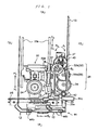
- FIG. 4 is a view schematically illustrating the internal structure of the disc apparatus, as viewed from the side.
- FIGS. 1 to 4 do not indicate a disc tray 10, and indicate only tray grooves 12 and a tray rack 13.
- the disc apparatus 90 includes the disc tray 10 (see FIG. 6), a traverse assembly unit (TAU) 20, and a loader chassis unit (LCU) 40 (see FIG. 5).
- the disc tray 10 carries a disc, and can go out and come in through a slit-shaped entrance 11b which is provided at a front panel 11a of an exterior housing 11 (the disc tray 10 can come in (loading)/go out (unloading)).
- the disc tray 10 is provided with the tray grooves 12 which curve step by step so as to have L shapes (a long portion of the L shape is placed along the length of the disc tray 10, and a short portion of the L shape is placed along the width of the disc tray 10), and the tray rack 13 which transmits driving force from a gear tray, which will be described later, along the length of the disc tray 10.
- a direction in which the front panel 11a is provided is expressed as a front part (F), and a direction which is opposite to the above direction is expressed as a rear part (R).
- a direction which is perpendicular to the above directions is expressed as a side part (S) (these will be denoted in the drawings).
- the traverse assembly unit 20 (TAU; see FIG. 5) includes a traverse assembly 21 (see FIG. 5), an optical pickup unit (OPU) 22, a lever trigger 23, a spindle motor 24, a traverse holder 25, a driving force transmitting gear set (gear set) 26, a transmission type sensor (encoder sensor) 27, and a contacting sensor (inner circumference arrival detecting sensor) 28 (see FIG. 2).
- the traverse assembly 21 is a frame on which the OPU 22, the lever trigger 23, the spindle motor 24, the traverse holder 25, the driving force transmitting gear set (gear set) 26, the transmission type sensor (encoder sensor) 27, and the contacting sensor (inner circumference arrival detecting sensor) 28 are mounted.
- the traverse assembly 21 is fixed to an end of the rear part of a loader chassis (which will be described later) with a screw.
- a floating rubber (damper) 21a is interposed (inserted) into each attaching hole provided in the traverse assembly 21.
- the floating rubber (damper) 21a covers portions around the attaching holes (circumference) and both end sides of the attaching holes, and has an opening respectively, which is so large that a round boss, which is provided at the loader chassis 41, can be inserted.
- the round bosses are inserted into the attaching holes, and the traverse assembly 21 is mounted on the loader chassis 41, and then the attaching holes of the traverse assembly 21 are fixed to the round bosses of the loader chassis 41 with attaching screws.
- the traverse assembly unit 20 can rotate around the attaching screw, thereby the traverse assembly unit 20 ascends when a disc is reproduced (in the case of chucking), and the traverse assembly unit 20 descends except for the case of chucking.
- the OCU 22 irradiates light (for example, a laser beam) on an optical disc to record/reproduce signals on/from the disc, and the OCU 22 is fixed to an OPU base 22b which is provided at shafts 22a to be movable, the shafts 22a being provided in the traverse assembly (the OPU 22 is mounted on the OPU base 22b).
- a semiconductor laser which irradiates a laser beam, an object lens which condenses the laser light on a recording surface of the disc, a light-receiving element which receives a laser beam reflected from the disc, etc., are mounted on the OPU base 22b.
- an OPU rack 31 which transmits the driving force of a driving motor 43 (which will be described later) is provided at the OPU base 22b.
- a main rack 31a which transmits driving force to move the OPU 22 (the OPU base 22b) is disposed at the lower part of the OPU rack 31, and a sub rack 31b which uses coil springs in order to prevent the generation of a gap between gear teeth of a first gear OPU 32 (a first gear OPU small gear 32b), which will be described later, and gear teeth of the main rack 31a, thereby to prevent backlash, is disposed at the upper part of the CPU rack 31.
- the OPU rack 31 forms a double rack in which the main rack 31a overlaps the sub rack 31b.
- the gear teeth of the sub rack 31b extend longer to the rear side than those of the main rack 31a, there can be two cases, that is, a case where the first gear OPU 32 (the first gear OPU small gear 32b) engages with 'the main rack 31a and the sub rack 31b', and a case where the first gear OPU 32 engages with 'the sub rack 31b'.
- a protrusion 31c is provided at a front end (a leading end of the front side) of the main rack 31a to push (turn on) a switch 28a of the contacting sensor 28, and an OPU rack boss (a first boss) 31d (see FIG. 1) which engages with a curved groove 23a of the lever trigger 23 (which will be described later) is formed (stands) at a front end of the sub rack 31b.
- the moving direction of the OPU 22 is the same as that of the disc tray 10 (the disc tray reciprocates between the front and rear sides).
- the lever trigger 23 includes the curved groove (a first groove) 23a with which the OPU rack boss 31d engages, and a coupling boss (not shown) which is fitted with a coupling groove 44a of a cam slider 44 (which will be described later).
- the gear teeth of the OPU rack 31 (the main rack 31a and the sub rack 31b) engage with or do not engage with the first gear OPU small gear 32b.
- lever trigger 23 is attached on the traverse assembly 21 such that the lever trigger 23 can reciprocate in the side direction (the vertical direction with respect to the moving direction of the disc tray) according to the location (moving) of the OPU rack boss 31d which is fitted with the curved groove 23a.
- the spindle motor 24 rotates a chucked disc.
- an elevating operation of the TAU 20 which is mounted on the spindle motor 24 for chucking (for reproducing the disc) will be described.
- the traverse holder 25 also acts as a power transmission member which is fixed to the front side of the traverse assembly 21.
- the traverse holder 25 includes a boss (T-boss; a second boss) 25a which engages with a cam groove 45 (which will be described later) of the cam slider 44, and ascends or descends the traverse assembly 21 (TAU 20) in conjunction with the movement of the cam slider 44.
- the driving force transmitting gear set 26 includes gears which transmit driving force from a driving motor (DC motor) provided at the loader chassis unit (LCU) 40 (see FIG. 5) to reciprocate the OPU 22, or gears which transmit driving force to move the cam slider 44.
- a driving motor DC motor
- LCU loader chassis unit
- first gear OPU 32, the second gear OPU 33, and a gear drive 34 are journaled on the traverse assembly 21.
- the first gear OPU 32 includes a first gear OPU large gear 32a which transmits the driving force of the driving motor 43, which will be described later, and the first gear OPU small gear (pinion gear) 32b which is provided below (in a direction near to the LCU 40) the center of the first gear OPU large gear 32a to transmit the driving force to the OPU rack 31. That is, in the first gear OPU 32, the first gear OPU large gear 32a is located on the first gear OPU small gear 32b, and the first gear OPU large gear 32a and the first gear OPU small gear 32b are journaled by the same shaft.
- the second gear OPU 33 includes a second gear OPU large gear 33a which transmits driving force from the first gear OPU small gear 32b and a second gear OPU small gear (pinion gear) 33b which is provided below (in a direction near to the LCU 40) the center of the second gear OPU large gear 33a to transmit the driving force to the gear drive 34. That is, in the second gear OPU 33, the second gear OPU large gear 33a is located on the second gear OPU small gear 33b, and the second gear OPU large gear 33a and the second gear OPU small gear 33b are journaled by the same shaft.
- the gear drive 34 transmits driving force from the second gear OPU small gear 33b, and is journaled on the traverse assembly 21.
- the transmission type sensor (optical sensor) 27 obtains position detecting signals corresponding to the rotating position of the pinion gear 43b which is provided at an output shaft 43a of the driving motor 43, by scanning slits of a slit plate 43c which is provided at the output shaft 43a.
- the transmission type sensor 27 is attached to a printed substrate 27a for a sensor which is attached to the traverse assembly 21, and has a reversed C-shaped vertical section. Also, in the transmission type sensor 27, a light-emitting element is provided at one end of the reversed C shape, and a light-receiving element is provided at the other end of the reversed C shape. In addition, slit blades 43c are disposed between both ends of the reversed C shape.
- the transmission type sensor 27 can obtain position detecting signals corresponding to the rotating position of the pinion gear 43b, based on whether the light-receiving element receives light from the light-emitting element.
- the contacting sensor 28 is provided at the rear side (the side facing the loader chassis 41) of the traverse assembly 21.
- a switch 28a is provided and is turned ON when the contacting sensor 28 comes into contact with the protrusion 31c provided at the main rack 31a.
- the disc apparatus 90 of the invention controls the encoder by using the switching (ON/OFF) of the contacting sensor and the position detecting signals. The control of the encoder will be described in detail.
- the loader chassis unit 40 includes the loader chassis (main body) 41, a gear tray 42, the driving motor (sled motor) 43, and the cam slider 44 (see FIG. 1).
- the loader chassis 41 is a main chassis which encases the TAU 20. Also, the loader chassis 41 includes the driving motor 43 and the cam slider 44.
- the gear tray 42 transmits driving force from the gear drive 34, and is journaled on the loader chassis 41.
- the gear tray 42 has a recessed portion (an intermittent portion 42a; see FIGS. 3 and 4) provided in the shaft direction, and is provided to engage with or not to engage with the gear drive 34.
- the driving motor 43 is a power source for opening and closing the disc tray 10, for reciprocating the OPU 22 and the cam slider 44 (an elevating operation of the TAU 20), and the pinion gear 43b is fitted with the output shaft 43a of the driving motor 43.
- a disc plate (slit plate 43c) in which slits are provided in a surface perpendicular to the output shaft 43a is provided (see FIGS. 7 and 8).
- the cam slider 44 includes a coupling groove 44a (see FIG. 3) with which a coupling boss of the lever trigger 23 (not shown) engages, standing bosses 44b (see FIG. 1) which engage with the tray groves 12 of the disc tray 10, a cam groove 45 (see FIG. 3) which engages with the T-boss 25a of the traverse holder 25, and a slider rack 44c which is fitted with the gear tray 42 (see FIG. 1).
- cam slider 44 is fitted with a groove rail (not shown) which is provided perpendicular to the moving direction of the disc tray 10 in the plane of the front side of the loader chassis 41, and can reciprocate along the groove rail.
- the cam groove 45 is composed of two opening grooves 45a and 45b (an upper opening groove 45a and a lower opening groove 45b) which become horizontal slits at the upper and lower sides (both end sides) of the cam groove 45 when the cam slider 44 is fitted with the groove rail, and an inclined opening groove 45c which connects the horizontal slits (see FIG. 3).
- the T-boss 25a of the traverse holder 25 is inserted into the cam groove 45, and the traverse holder 25 ascends when the T-boss 25a moves to the upper opening groove 45a, and the traverse holder 25 descends when the T-boss 25a moves to the lower opening groove 45b.
- each member the OPU 22, the TAU 20, and the disc tray 10.
- 'solid lines' which connect each member in FIGS. 10 to 14 mean mechanical fixation (injection or screw-fastening), and 'one-dotted lines' mean engagement by the gear teeth.
- 'double lines' mean engagement by the cam, and 'dashed lines' mean that the both are intercepted.
- 'halftone dotted areas' mean members which contribute to the moving process or the converting process.
- the movement of the OPU 22 in the disc apparatus 90 according to the invention will be described.
- a disc such as a DVD
- the user pushes an opening and closing button provided at the exterior housing 11.
- the driving motor 43 rotates in an A1 direction (clockwise direction), and then the pinion gear 43b also rotates in the A1 direction.
- the first gear OPU large gear 32a that is, the first gear OPU 32
- the first gear OPU small gear 32b which is connected with the first gear OPU large gear 32a (connected with each other) also rotates in the B1 direction
- the OPU rack 31 (the main rack 31a and the sub rack 31b) which engages with the first gear OPU small gear 32b moves in a C1 direction.
- the OPU base 22b to which the OPU rack 31 is attached also moves, and the OPU 22 moves in the C1 direction (the inner circumference direction of the disc).
- the driving force of the driving motor 43 is always transmitted to the second gear OPU small gear 33b (the second gear OPU) and the gear drive 34.
- the gear drive 34 is located in the recessed portion 42a of the gear tray 42 (see FIGS. 3 and 4). Therefore, the driving force is not transmitted to the gear tray 42 via the gear drive 34, and thus the TAU 20 and the disc tray 10 do not move.
- the sub rack 31b further moves to the inner circumference of the disc. Therefore, the OPU rack boss 31d provided at the sub rack 31b becomes fitted with the curved groove 23a of the lever trigger 23, and then the OPU 22 further moves in the C1 direction.
- the lever trigger 23 moves in a D1 direction in conjunction with the movement of the sub rack 31b in the C1 direction. Then, the OPU rack boss 31d is locked in the end portion of the curved groove 23a. Therefore, the main rack 31a is disengaged from the first gear OPU small gear 32b, and the OPU 22 stops at the inner circumference of the disc.
- a coupling boss is provided at the lever trigger 23 which moves in the D1 direction in conjunction with the movement of the sub rack 31b, and the coupling boss is fitted with the coupling groove 44a of the cam slider 44 (see FIG. 3). Therefore, the cam slider 44 slightly moves (slides) in an E1 direction in conjunction with the movement of the lever trigger 23. Then, the cam slider rack 44c of the cam slider 44 also moves in the E1 direction.
- the cam slider 44 further moves in the E1 direction by the driving force of the driving motor 43. Also, as shown in FIG. 3, since the T-boss 25a of the traverse holder 25 is fitted with the cam groove 45 of the cam slider 44, the T-boss 25a moves across the upper opening groove 45a, the inclined opening groove 45c, and the lower opening groove 45b sequentially in conjunction with the movement of the cam slider 44. Then, the traverse holder 25 descends in a G1 direction in conjunction with the movement of the T-boss 25a. As a result, the traverse assembly 21 to which the traverse holder 25 is attached and the TAU 20 descend.
- the cam slider 44 further slides in the E1 direction. Therefore, the standing boss 44b engaging with the tray grooves 12 of the disc tray 10 also moves in the E1 direction. Then, the standing boss 44b moves to the longitudinal portion of the tray grooves which are curved step by step so as to have L shapes. Therefore, the disc tray 10 slightly moves in an H1 direction (the front direction) while the standing boss 49b moves.
- the tray rack 13 also moves in the H1 direction, and then engages with the gear tray 42.
- the cam slider 44 is disengaged from the gear tray 42.
- the tray rack 13 engages with the gear tray 42
- the tray rack 13 also moves in the H1 direction in conjunction with the rotation of the gear tray 42 in the F1 direction. That is, the disc tray 10 moves to the front side, and then an opening operation starts.
- the disc apparatus 90 of the invention three operations, that is, an OPU operation, a TAU operation, and a disc tray operation, can be performed by the rotation of a single driving motor 43.
- the slit plate 43c is provided at the driving motor 43, and the position detecting signals corresponding to the rotating position of the pinion gear 43b can be obtained by using the transmission type sensor 27. Therefore, it is possible to perform encoder control.
- the encoder control will be described with reference to FIG. 15.
- a user sets the disc in the disc apparatus 90.
- the user pushes an opening and closing button which is provided at the exterior housing 11.
- a command for opening the disc tray is issued to the control unit (not shown) which is connected to the driving motor 43.
- the control unit When receiving the command, the control unit supplies a voltage V0 (a first voltage) to the driving motor 43. Then, the driving motor 43 moves the OPU 22 to the inner circumference of the disc, based on the voltage V0.
- V0 a first voltage
- the driving motor 43 moves the OPU 22 to the inner circumference of the disc, based on the voltage V0.
- the switch (SW) 28a of the contacting sensor 28 is pressed by the protrusion 31c of the main rack 31a, and is then turned ON (SW-ON).
- the control unit When the control unit receives the ON signal, the control unit applies a voltage V1 (a second voltage) to rotate the driving motor 43 as many as a prescribed number of slits (S1; a predetermined number of rotations). Then, the TAU 20 descends by a predetermined distance according to the number of the slits.
- V1 a second voltage
- the control unit applies a voltage V2 (a third voltage) to rotate the driving motor 43 as many as a prescribed number of slits (S2; a predetermined number of rotations). Then, the control unit opens the disc tray 10 by a previously determined distance according to the number of the slits. However, when the disc tray 10 is completely opened, it is desired to stop the disc tray 10 smoothly. Therefore, in the invention, the control unit gradually decreases the voltage V2 (finally, to the voltage 0 V), and rotates the driving motor 43 as many as the prescribed number of slits (S3; a predetermined number of rotations).
- V2 a third voltage
- the control unit gradually applies a voltage V3 (a fourth voltage), which is an inverse voltage of the voltages V1 and V2, as much as a prescribed number of slits (S4; a predetermined number of rotations), and rotates the driving motor 43 as many as a prescribed number of slits (S5; a predetermined number of rotations), thereby closing the disc tray 10.
- V3 a fourth voltage
- the control unit applies a voltage V4 (a fifth voltage) to rotate the driving motor 43 until the switch 28a of the contacting sensor 28 is turned OFF. That is, the driving motor is rotated until the TAU 20 ascends and then the lock of the OPU 22 is released. In addition, when the lock of the OPU is released, the OPU 22 can move to the outer circumference. Also, when the control unit receives the OFF signal (lock releasing signal), the driving motor 43 is stopped.
- V4 a fifth voltage
- the number of slits (S1 to S5) can vary arbitrarily.
- members can be moved very smoothly. That is, if the voltage applied to the driving motor 43 varies when the disc tray is opened or closed, the disc tray can be opened or closed very smoothly, and proper driving force can also be supplied in the ascent and descent of the traverse assembly unit when high rotating force is required (high torque is required).
- the encoder control makes it possible to know the location of the disc tray when the disc tray is completely opened, a tray open switch is not required. As a result, it is possible to reduce the manufacturing costs of the disc apparatus 90 of the invention, and to secure a high-quality moving operation of the disc tray.
- the invention is useful for a disc apparatus for a CD, a DVD, and the like.
Landscapes
- Feeding And Guiding Record Carriers (AREA)
- Moving Of Heads (AREA)
Abstract
Description
- The present invention relates to a disc apparatus for, for example, a CD and a DVD.
- In a commonly used disc apparatus (for example, see JP-A-2002-100099, JP-A-6-119698, JP-A-6-338119 and JP-A-2001-216702), a disc tray (tray) is opened or closed (unloading/loading) at a slit-shaped entrance which is provided in a front panel of an exterior housing by driving force of a driving motor.
- Generally, the disc apparatus includes a switch (tray open switch) for detecting whether the tray is opened completely, in order to stop the operation of the driving motor for driving the disc tray, when the disc tray is opened (when the opening of the tray is completed).
- In addition, there can be different types of disc apparatuses, such as a disc apparatus in which a stopper or the like is provided in the vicinity of a slit-shaped entrance and in which the operation of the driving motor is stopped when the tray comes into contact with the stopper, as disclosed in JP-A-6-338119, and a disc apparatus in which the operation of the driving motor of the disc tray is stopped after a predetermined time elapsed, as disclosed in JP-A-2001-216702.
- However, in the case in which the tray open switch is provided in the disc apparatus, the tray open switch must be provided at a position where the tray open switch does not obstruct the operation of an OPU (optical pickup unit) and the driving motor. That is, since the tray open switch is provided in a limited space inside the disc apparatus, which causes the flexibility of the design to be lowered. Further, it is required to provide, for example, a dedicated printed circuit board for controlling the tray open switch, which causes the flexibility of the design to be further lowered.
- In addition, the provision of the tray open switch increases the number of components which constitute the disc apparatus, resulting in an increase in the manufacturing costs of the disc apparatus.
- Also, in the movement control of the disk tray by time control, it is common to set the time longer than the required time in order to prevent the disc tray from stopping in the middle of an opening operation. In addition, many disc apparatuses include a stopper which is provided in the vicinity of the slit-shaped entrance to stop the disc tray when the disc tray comes into contact with the stopper. Therefore, the disc tray does not stop smoothly, and thus a high-quality operation cannot be performed.
- The present invention has been made to solve the above problems. An object of the invention is to provide a disc apparatus in which a tray open switch which detects whether a disc tray is opened completely is not provided, thereby improving the flexibility of the design, and thus the manufacturing costs of the disc apparatus can be decreased, and a high-quality moving operation of the disc tray can be guaranteed.
- According to an aspect of the invention, a disk apparatus includes a disc tray on which a disc is mounted; an optical pickup unit (OPU) which irradiates a light beam on the disc; a traverse assembly unit (TAU) on which the optical pickup unit is mounted; a driving motor which is a power source for operating the disc tray, the optical pickup unit, and the traverse assembly unit; an inner circumference arrival sensor which detects whether the optical pickup unit arrives at the inner circumference of the disc; and an encoder sensor which detects the number of rotations of the driving motor when the driving motor rotates clockwise or counterclockwise. In the disk apparatus, based on the number of rotations of the driving motor in the clockwise direction which is detected by the encoder sensor, the optical pickup unit is moved to the inner circumference of the disc, and then the traverse assembly unit descends, so that the disc tray is opened.
- According to the above-mentioned structure, since 'the optical pickup unit', 'the traverse assembly unit', and 'the disc tray' can be operated based on the encoder control, the respective members can be operated in an extremely smooth manner. In addition, since it is possible to know the location of the disc tray when the disc tray is completely opened by the encoder control, a tray open switch is not required. As a result, the flexibility of the design can be improved, and the manufacturing costs of the disc apparatus can be decreased. In addition, a high-quality moving operation of the disc tray can be guaranteed.
- In addition, in the above-mentioned structure, preferably, the optical pickup unit is moved to the inner circumference of the disc by rotating force of the driving motor based on a first voltage. Then, as soon as the inner circumference arrival detecting sensor detects that the optical pickup unit arrives at the inner circumference of the disc, the number of rotations of the driving motor be reduced to a first predetermined number of rotations by rotating force based on a second voltage to move the traverse assembly unit down. Subsequently, the number of rotations of the driving motor is reduced to a second predetermined number of rotations by rotating force based on a third voltage, and then the number of rotations of the driving motor is reduced to a third predetermined number of rotations by gradually lowering the third voltage to open the disc tray. In this case, absolute values of the first to third voltages satisfy the following relationship: the first voltage < the third voltage < the second voltage.
- Also, in the above-mentioned structure, preferably, when the disc tray is closed, the traverse assembly unit ascends, and the optical pickup unit is moved to the outer circumference of the disc by the counterclockwise rotation of the driving motor. In addition, the number of rotations of the driving motor increases up to a fourth predetermined number of rotations by gradually increasing the voltage to a fourth predetermined voltage, and then the number of rotations of the driving motor increases to a fifth predetermined number of rotations by rotating force based on the fourth voltage to close the disc tray. Then, until the inner circumference arrival detecting sensor detects that the optical pickup unit is moved away from the inner circumference of the disc, the traverse assembly unit ascends by rotating force based on the fifth voltage. In this case, absolute values of the fourth and fifth voltages satisfy the following relationship: the fourth voltage < the fifth voltage.
- As described above, if the voltage applied to the driving motor is varied, at the time of the opening or closing of the disc tray, the disc tray can be opened or closed in an extremely smooth manner, and appropriate driving force can be supplied to the respective members even when the traverse assembly unit ascends, that is, even when strong rotating force is required (when high torque is required).
- Further, according to another aspect of the invention, a disc apparatus includes a driving motor which is a power source; a disc tray that includes a tray rack for receiving driving force for opening and closing based on driving force of the driving motor and tray grooves, which are conjunction mechanisms, and that is provided to be openable in a main body of the disc apparatus in a sliding manner, with a disk mounted thereon; an optical pickup unit which includes an OPU rack having a first boss, which irradiates a light beam onto the disc, which is provided such that it can reciprocate between inner and outer circumference of the disc, and which receives reciprocating driving force based on the driving force of the driving motor; an inner circumference arrival detecting sensor which detects whether the optical pickup unit arrives at the inner circumference of the disc, a traverse assembly unit which is provided such that it can be elevated, the traverse assembly unit including a traverse holder having a second boss for receiving elevating driving force based on the driving force of the driving motor; a lever trigger having a coupling boss and a first groove which engages with the first boss of the OPU rack so as to move in conjunction with the movement of the OPU; and a gear set which transmits the driving force of the driving motor; a loader chassis unit which includes the driving motor mounted thereon; a gear tray having an intermittent portion that receives or not transmits the driving force of the driving motor via the gear set journaled thereon; and a cam slider including a cam slider rack which engages with the gear tray, a cam groove which engages with the second boss of the traverse holder, a standing boss which engages with the tray grooves of the disc tray, a coupling groove which engages with a coupling boss of the lever trigger, the cam slider interlocking the traverse holder and the disc tray and being moved in conjunction with the movement of the lever trigger; and an encoder sensor which detects the number of rotations of the driving motor when the driving motor rotates clockwise or counterclockwise. In the disk apparatus, the OPU rack receives the driving force transmitted via the gear set, and then moves the optical pickup unit to the inner circumference of the disc, based on the number of rotations of the driving motor in the clockwise direction which is detected by the encoder sensor. The lever trigger having the first groove engaging with the first boss is moved in conjunction with the movement of the first boss to the inner circumference by the movement of the OPU rack. The cam slider having the coupling groove that engages with the coupling boss slides is moved in conjunction with the movement of the coupling bass according to the movement of the lever trigger. The gear tray engaging with the cam slider rack by the sliding operation receives the driving force via the gear set to be rotated. The cam slider further slides by the rotation of the gear tray to operate the traverse holder having second bass that engages with the cam groove, thereby moving the traverse assembly unit downward The disc tray having the tray grooves that engage with the standing boss moves in the opening direction in conjunction with the sliding of the cam slider, and the tray rack engages with the gear tray, so that the disk tray is opened by the driving force transmitted through the gear set.
- The invention operates 'the OPU', 'the TAU', and 'the disc tray' based on the encoder control such that the respective members can be operated in an extremely smooth manner. Also, since the location of the disc tray where the disc tray is completely opened can be detected by the encoder control, a tray open switch is not required.
- These and other objects and advantages of this invention will become more fully apparent from the following detailed description taken with the accompanying drawings in which:
- FIG. 1 is a view schematically illustrating the internal structure of a disc apparatus of the invention with a loader chassis, which is shown in FIG. 5, removed;
- FIG. 2 is a view schematically illustrating the internal structure of the disc apparatus, as viewed from the lower side;
- FIG. 3 is a view schematically illustrating the internal structure of the disc apparatus, as viewed from a front panel;
- FIG. 4 is a view schematically illustrating the internal structure of the disc apparatus, as viewed from the side;
- FIG. 5 is a view schematically illustrating the internal structure of the disc apparatus of the invention;
- FIG. 6 is a perspective view of the disc apparatus of the invention;
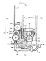
- FIG. 7 is a view schematically illustrating the structure of a transmission type sensor, a driving motor, a pinion gear, and a slit plate, as viewed from the upper side;
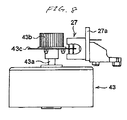
- FIG. 8 is a view schematically illustrating the structure of the transmission type sensor, the driving motor, the pinion gear, and the slit plate, as viewed from the side;
- FIG. 9 is a partially enlarged view of FIG. 2;
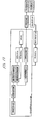
- FIG. 10 is a view explaining the movement of an OPU;
- FIG. 11 is a view explaining the conversion of the movement of the OPU into the movement of a traverse assembly unit;
- FIG. 12 is a view explaining the movement of the traverse assembly unit;
- FIG. 13 is a view explaining the conversion of the movement of the traverse assembly unit into the movement of a disc tray;
- FIG. 14 is a view explaining the movement of the disc tray (tray opening); and
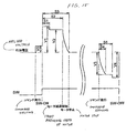
- FIG. 15 is a view explaining encoder control.
- Hereinafter, an embodiment of the present invention will be described with reference to the accompanying drawings.
- FIGS. 1 to 6 show a
disc apparatus 90 of the invention. FIG. 6 is a perspective view of the disc apparatus. FIG. 5 is a view schematically illustrating the internal structure of the disc apparatus, as viewed from an upper side, and FIG. 1 is a view schematically illustrating the internal structure of the disc apparatus with a loader chassis (which will be described later) shown in FIG. 5 removed. FIG. 2 is a view schematically illustrating the internal structure of the disc apparatus, as viewed from a lower side (a bottom part), and FIG. 3 is a view schematically illustrating the internal structure of the disc apparatus, as viewed from a front panel. FIG. 4 is a view schematically illustrating the internal structure of the disc apparatus, as viewed from the side. For the convenience of explanation, FIGS. 1 to 4 do not indicate adisc tray 10, and indicate onlytray grooves 12 and atray rack 13. - As regards the disc apparatus
- The
disc apparatus 90 includes the disc tray 10 (see FIG. 6), a traverse assembly unit (TAU) 20, and a loader chassis unit (LCU) 40 (see FIG. 5). - As regards the disc tray
- As shown in FIG. 6, the
disc tray 10 carries a disc, and can go out and come in through a slit-shapedentrance 11b which is provided at afront panel 11a of an exterior housing 11 (thedisc tray 10 can come in (loading)/go out (unloading)). - Also, in order to reciprocate the
disc tray 10, as shown in FIG. 1, thedisc tray 10 is provided with thetray grooves 12 which curve step by step so as to have L shapes (a long portion of the L shape is placed along the length of thedisc tray 10, and a short portion of the L shape is placed along the width of the disc tray 10), and thetray rack 13 which transmits driving force from a gear tray, which will be described later, along the length of thedisc tray 10. - Hereinafter, a direction in which the
front panel 11a is provided is expressed as a front part (F), and a direction which is opposite to the above direction is expressed as a rear part (R). In addition, a direction which is perpendicular to the above directions is expressed as a side part (S) (these will be denoted in the drawings). - As regards the traverse assembly unit
- As shown in FIG. 1, the traverse assembly unit 20 (TAU; see FIG. 5) includes a traverse assembly 21 (see FIG. 5), an optical pickup unit (OPU) 22, a
lever trigger 23, aspindle motor 24, atraverse holder 25, a driving force transmitting gear set (gear set) 26, a transmission type sensor (encoder sensor) 27, and a contacting sensor (inner circumference arrival detecting sensor) 28 (see FIG. 2). - The
traverse assembly 21 is a frame on which theOPU 22, thelever trigger 23, thespindle motor 24, thetraverse holder 25, the driving force transmitting gear set (gear set) 26, the transmission type sensor (encoder sensor) 27, and the contacting sensor (inner circumference arrival detecting sensor) 28 are mounted. In addition, thetraverse assembly 21 is fixed to an end of the rear part of a loader chassis (which will be described later) with a screw. - Specifically, as shown in FIG. 5, a floating rubber (damper) 21a is interposed (inserted) into each attaching hole provided in the
traverse assembly 21. The floating rubber (damper) 21a covers portions around the attaching holes (circumference) and both end sides of the attaching holes, and has an opening respectively, which is so large that a round boss, which is provided at theloader chassis 41, can be inserted. The round bosses are inserted into the attaching holes, and thetraverse assembly 21 is mounted on theloader chassis 41, and then the attaching holes of thetraverse assembly 21 are fixed to the round bosses of theloader chassis 41 with attaching screws. - When the attaching holes are fixed to the round bosses with the attaching screws, it is preferable to maintain a certain gap between heads of the attaching screws and the
loader chassis 41. Then, thetraverse assembly unit 20 can rotate around the attaching screw, thereby thetraverse assembly unit 20 ascends when a disc is reproduced (in the case of chucking), and thetraverse assembly unit 20 descends except for the case of chucking. - The
OCU 22 irradiates light (for example, a laser beam) on an optical disc to record/reproduce signals on/from the disc, and theOCU 22 is fixed to anOPU base 22b which is provided atshafts 22a to be movable, theshafts 22a being provided in the traverse assembly (theOPU 22 is mounted on theOPU base 22b). Specifically, a semiconductor laser which irradiates a laser beam, an object lens which condenses the laser light on a recording surface of the disc, a light-receiving element which receives a laser beam reflected from the disc, etc., are mounted on theOPU base 22b. - In addition, an
OPU rack 31 which transmits the driving force of a driving motor 43 (which will be described later) is provided at theOPU base 22b. Specifically, amain rack 31a which transmits driving force to move the OPU 22 (theOPU base 22b) is disposed at the lower part of theOPU rack 31, and asub rack 31b which uses coil springs in order to prevent the generation of a gap between gear teeth of a first gear OPU 32 (a first gear OPUsmall gear 32b), which will be described later, and gear teeth of themain rack 31a, thereby to prevent backlash, is disposed at the upper part of theCPU rack 31. - That is, the
OPU rack 31 forms a double rack in which themain rack 31a overlaps thesub rack 31b. However, since the gear teeth of thesub rack 31b extend longer to the rear side than those of themain rack 31a, there can be two cases, that is, a case where the first gear OPU 32 (the first gear OPUsmall gear 32b) engages with 'themain rack 31a and thesub rack 31b', and a case where thefirst gear OPU 32 engages with 'thesub rack 31b'. - In addition, as shown in FIG. 2, a
protrusion 31c is provided at a front end (a leading end of the front side) of themain rack 31a to push (turn on) aswitch 28a of the contactingsensor 28, and an OPU rack boss (a first boss) 31d (see FIG. 1) which engages with acurved groove 23a of the lever trigger 23 (which will be described later) is formed (stands) at a front end of thesub rack 31b. Also, the moving direction of theOPU 22 is the same as that of the disc tray 10 (the disc tray reciprocates between the front and rear sides). - The
lever trigger 23 includes the curved groove (a first groove) 23a with which theOPU rack boss 31d engages, and a coupling boss (not shown) which is fitted with acoupling groove 44a of a cam slider 44 (which will be described later). In addition, according to the location (moving) of theOPU rack boss 31d which is fitted with thecurved groove 23a, the gear teeth of the OPU rack 31 (themain rack 31a and thesub rack 31b) engage with or do not engage with the first gear OPUsmall gear 32b. Also, thelever trigger 23 is attached on thetraverse assembly 21 such that thelever trigger 23 can reciprocate in the side direction (the vertical direction with respect to the moving direction of the disc tray) according to the location (moving) of theOPU rack boss 31d which is fitted with thecurved groove 23a. - The
spindle motor 24 rotates a chucked disc. Hereinafter, an elevating operation of theTAU 20 which is mounted on thespindle motor 24 for chucking (for reproducing the disc) will be described. - The
traverse holder 25 also acts as a power transmission member which is fixed to the front side of thetraverse assembly 21. Specifically, thetraverse holder 25 includes a boss (T-boss; a second boss) 25a which engages with a cam groove 45 (which will be described later) of thecam slider 44, and ascends or descends the traverse assembly 21 (TAU 20) in conjunction with the movement of thecam slider 44. - The driving force transmitting gear set 26 includes gears which transmit driving force from a driving motor (DC motor) provided at the loader chassis unit (LCU) 40 (see FIG. 5) to reciprocate the
OPU 22, or gears which transmit driving force to move thecam slider 44. - Specifically, the
first gear OPU 32, thesecond gear OPU 33, and agear drive 34 are journaled on thetraverse assembly 21. - The
first gear OPU 32 includes a first gear OPUlarge gear 32a which transmits the driving force of the drivingmotor 43, which will be described later, and the first gear OPU small gear (pinion gear) 32b which is provided below (in a direction near to the LCU 40) the center of the first gear OPUlarge gear 32a to transmit the driving force to theOPU rack 31. That is, in thefirst gear OPU 32, the first gear OPUlarge gear 32a is located on the first gear OPUsmall gear 32b, and the first gear OPUlarge gear 32a and the first gear OPUsmall gear 32b are journaled by the same shaft. - The
second gear OPU 33 includes a second gear OPUlarge gear 33a which transmits driving force from the first gear OPUsmall gear 32b and a second gear OPU small gear (pinion gear) 33b which is provided below (in a direction near to the LCU 40) the center of the second gear OPUlarge gear 33a to transmit the driving force to thegear drive 34. That is, in thesecond gear OPU 33, the second gear OPUlarge gear 33a is located on the second gear OPUsmall gear 33b, and the second gear OPUlarge gear 33a and the second gear OPUsmall gear 33b are journaled by the same shaft. - The gear drive 34 transmits driving force from the second gear OPU
small gear 33b, and is journaled on thetraverse assembly 21. - The transmission type sensor (optical sensor) 27 obtains position detecting signals corresponding to the rotating position of the
pinion gear 43b which is provided at anoutput shaft 43a of the drivingmotor 43, by scanning slits of aslit plate 43c which is provided at theoutput shaft 43a. - Specifically, as shown in FIG. 7 (a plan view as viewed from the upper side) and FIG. 8 (a plan view as viewed from the bottom), the
transmission type sensor 27 is attached to a printedsubstrate 27a for a sensor which is attached to thetraverse assembly 21, and has a reversed C-shaped vertical section. Also, in thetransmission type sensor 27, a light-emitting element is provided at one end of the reversed C shape, and a light-receiving element is provided at the other end of the reversed C shape. In addition, slitblades 43c are disposed between both ends of the reversed C shape. Therefore, according to the rotation of theslit blades 43c, there can be two cases, that is, a case where the light-receiving element can receive light from the light-emitting element and a case where the light-receiving element cannot receive light from the light-emitting element. Therefore, thetransmission type sensor 27 can obtain position detecting signals corresponding to the rotating position of thepinion gear 43b, based on whether the light-receiving element receives light from the light-emitting element. - As shown in FIG. 9, which is an enlarged view of FIG. 2, the contacting
sensor 28 is provided at the rear side (the side facing the loader chassis 41) of thetraverse assembly 21. In addition, aswitch 28a is provided and is turned ON when the contactingsensor 28 comes into contact with theprotrusion 31c provided at themain rack 31a. Meanwhile, thedisc apparatus 90 of the invention controls the encoder by using the switching (ON/OFF) of the contacting sensor and the position detecting signals. The control of the encoder will be described in detail. - As regards the loader chassis unit
- The
loader chassis unit 40, as shown in FIG. 5, includes the loader chassis (main body) 41, agear tray 42, the driving motor (sled motor) 43, and the cam slider 44 (see FIG. 1). - The
loader chassis 41 is a main chassis which encases theTAU 20. Also, theloader chassis 41 includes the drivingmotor 43 and thecam slider 44. - The
gear tray 42 transmits driving force from thegear drive 34, and is journaled on theloader chassis 41. In addition, thegear tray 42 has a recessed portion (anintermittent portion 42a; see FIGS. 3 and 4) provided in the shaft direction, and is provided to engage with or not to engage with thegear drive 34. - The driving
motor 43 is a power source for opening and closing thedisc tray 10, for reciprocating theOPU 22 and the cam slider 44 (an elevating operation of the TAU 20), and thepinion gear 43b is fitted with theoutput shaft 43a of the drivingmotor 43. In addition, a disc plate (slit plate 43c) in which slits are provided in a surface perpendicular to theoutput shaft 43a is provided (see FIGS. 7 and 8). - The
cam slider 44 includes acoupling groove 44a (see FIG. 3) with which a coupling boss of the lever trigger 23 (not shown) engages, standingbosses 44b (see FIG. 1) which engage with thetray groves 12 of thedisc tray 10, a cam groove 45 (see FIG. 3) which engages with the T-boss 25a of thetraverse holder 25, and aslider rack 44c which is fitted with the gear tray 42 (see FIG. 1). - In addition, the
cam slider 44 is fitted with a groove rail (not shown) which is provided perpendicular to the moving direction of thedisc tray 10 in the plane of the front side of theloader chassis 41, and can reciprocate along the groove rail. - Further, the
cam groove 45 is composed of two openinggrooves upper opening groove 45a and alower opening groove 45b) which become horizontal slits at the upper and lower sides (both end sides) of thecam groove 45 when thecam slider 44 is fitted with the groove rail, and aninclined opening groove 45c which connects the horizontal slits (see FIG. 3). In addition, the T-boss 25a of thetraverse holder 25 is inserted into thecam groove 45, and thetraverse holder 25 ascends when the T-boss 25a moves to theupper opening groove 45a, and thetraverse holder 25 descends when the T-boss 25a moves to thelower opening groove 45b. - As regards the movement of each member
- Hereinafter, the movement of each member (the
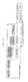
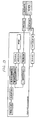
OPU 22, theTAU 20, and the disc tray 10) will be described with reference to FIGS. 1 to 14, particularly FIGS. 10 to 14. Meanwhile, 'solid lines' which connect each member in FIGS. 10 to 14 mean mechanical fixation (injection or screw-fastening), and 'one-dotted lines' mean engagement by the gear teeth. Also, 'double lines' mean engagement by the cam, and 'dashed lines' mean that the both are intercepted. Further, 'halftone dotted areas' mean members which contribute to the moving process or the converting process. - As regards the movement of the OPU (see FIG. 10)
- Hereinafter, the movement of the
OPU 22 in thedisc apparatus 90 according to the invention will be described. For example, when the reproduction of a disc, such as a DVD, is finished and a user wants to unload the disc from the disc apparatus 90 (that is, when thedisc tray 10 is made open), the user pushes an opening and closing button provided at theexterior housing 11. - In this case, first, the driving
motor 43 rotates in an A1 direction (clockwise direction), and then thepinion gear 43b also rotates in the A1 direction. In addition, the first gear OPUlarge gear 32a (that is, the first gear OPU 32) which engages with thepinion gear 43b rotates in a B1 direction. Then, the first gear OPUsmall gear 32b which is connected with the first gear OPUlarge gear 32a (connected with each other) also rotates in the B1 direction, and the OPU rack 31 (themain rack 31a and thesub rack 31b) which engages with the first gear OPUsmall gear 32b moves in a C1 direction. Then, theOPU base 22b to which theOPU rack 31 is attached also moves, and theOPU 22 moves in the C1 direction (the inner circumference direction of the disc). - Meanwhile, since the first gear OPU
small gear 32b always engages with the second gear OPUlarge gear 33a and the second gear OPUsmall gear 33b always engages with thegear drive 34, the driving force of the drivingmotor 43 is always transmitted to the second gear OPUsmall gear 33b (the second gear OPU) and thegear drive 34. However, when theOPU 22 moves, thegear drive 34 is located in the recessedportion 42a of the gear tray 42 (see FIGS. 3 and 4). Therefore, the driving force is not transmitted to thegear tray 42 via thegear drive 34, and thus theTAU 20 and thedisc tray 10 do not move. - As regards the conversion of the movement of the OPU into the movement of the traverse assembly unit (see FIG. 11)
- If the driving
motor 43 is rotated even after theOPU 22 arrives at the inner circumferential position of the disc, only thesub rack 31b extending toward the rear side from themain rack 31a and thesub rack 31b which engage with the first gear OPUsmall gear 32b engages with the first gear OPUsmall gear 32b. - Then, the
sub rack 31b further moves to the inner circumference of the disc. Therefore, theOPU rack boss 31d provided at thesub rack 31b becomes fitted with thecurved groove 23a of thelever trigger 23, and then theOPU 22 further moves in the C1 direction. Thelever trigger 23 moves in a D1 direction in conjunction with the movement of thesub rack 31b in the C1 direction. Then, theOPU rack boss 31d is locked in the end portion of thecurved groove 23a. Therefore, themain rack 31a is disengaged from the first gear OPUsmall gear 32b, and theOPU 22 stops at the inner circumference of the disc. - As regards the movement (descent) of the TAU (see FIG. 12)
- On the other hand, a coupling boss is provided at the
lever trigger 23 which moves in the D1 direction in conjunction with the movement of thesub rack 31b, and the coupling boss is fitted with thecoupling groove 44a of the cam slider 44 (see FIG. 3). Therefore, thecam slider 44 slightly moves (slides) in an E1 direction in conjunction with the movement of thelever trigger 23. Then, thecam slider rack 44c of thecam slider 44 also moves in the E1 direction. - When the
cam slider rack 44c moves in the E1 direction, thegear tray 42 engaging with thecam slider rack 44c rotates in the F1 direction. Then, the location of the recessedportion 42a which is provided at thegear tray 42 varies (see FIGS. 3 and 4), and thegear drive 34 engages with thegear tray 42. In this way, when thegear drive 34 engages with thegear tray 42, the driving force of the drivingmotor 43 is transmitted to thecam slider rack 44c and, consequently, to thecam slider 44 via thegear tray 42. - Therefore, the
cam slider 44 further moves in the E1 direction by the driving force of the drivingmotor 43. Also, as shown in FIG. 3, since the T-boss 25a of thetraverse holder 25 is fitted with thecam groove 45 of thecam slider 44, the T-boss 25a moves across theupper opening groove 45a, theinclined opening groove 45c, and thelower opening groove 45b sequentially in conjunction with the movement of thecam slider 44. Then, thetraverse holder 25 descends in a G1 direction in conjunction with the movement of the T-boss 25a. As a result, thetraverse assembly 21 to which thetraverse holder 25 is attached and theTAU 20 descend. - As regards the conversion of the movement of the TAU into the movement of the disc tray (see FIG. 13)
- Like the above, when the
TAU 20 descends and the drivingmotor 43 is further rotated, thecam slider 44 further slides in the E1 direction. Therefore, the standingboss 44b engaging with thetray grooves 12 of thedisc tray 10 also moves in the E1 direction. Then, the standingboss 44b moves to the longitudinal portion of the tray grooves which are curved step by step so as to have L shapes. Therefore, thedisc tray 10 slightly moves in an H1 direction (the front direction) while the standing boss 49b moves. - As a result, the
tray rack 13 also moves in the H1 direction, and then engages with thegear tray 42. In addition, as soon as thetray rack 13 engages with thegear tray 42, thecam slider 44 is disengaged from thegear tray 42. - As regards the movement (tray opening) of the disc tray (see FIG. 14)
- As described above, when the
tray rack 13 engages with thegear tray 42, thetray rack 13 also moves in the H1 direction in conjunction with the rotation of thegear tray 42 in the F1 direction. That is, thedisc tray 10 moves to the front side, and then an opening operation starts. - As described above, in the
disc apparatus 90 of the invention, three operations, that is, an OPU operation, a TAU operation, and a disc tray operation, can be performed by the rotation of asingle driving motor 43. In addition, theslit plate 43c is provided at the drivingmotor 43, and the position detecting signals corresponding to the rotating position of thepinion gear 43b can be obtained by using thetransmission type sensor 27. Therefore, it is possible to perform encoder control. - Further, in the above description, operations related to 'the movement of the OPU to the inner circumference of the disc', 'the descent of the TAU', and 'the opening of the disc tray' have been described. However, when the driving
motor 43 is rotated in the A2 direction (counterclockwise), the respective members rotate/move in the B2 to H2 directions opposite to the B1 to H1 directions, and then operations related to 'the movement of the OPU to the outer circumference of the disc', 'the ascent of the TAU', and 'the closing of the disc tray' can also be performed. In addition, since theOPU 22 is locked as soon as theOPU 22 arrives at the inner circumference of the disc, the position of theOPU 22 does not vary during the descent of theTAU 20. On the other hand, the lock of theOPU 22 is released as soon as theTAU 20 ascends completely. - As regards encoder control
- AS regards encoder control when the disc tray is opened
- Hereinafter, the encoder control will be described with reference to FIG. 15. For example, when a disc, such as a DVD, is reproduced in the disc apparatus, a user sets the disc in the
disc apparatus 90. In this case, first, the user pushes an opening and closing button which is provided at theexterior housing 11. Then, a command for opening the disc tray is issued to the control unit (not shown) which is connected to the drivingmotor 43. - When receiving the command, the control unit supplies a voltage V0 (a first voltage) to the driving
motor 43. Then, the drivingmotor 43 moves theOPU 22 to the inner circumference of the disc, based on the voltage V0. When theOPU 22 arrives at the inner circumference of the disc, the switch (SW) 28a of the contactingsensor 28 is pressed by theprotrusion 31c of themain rack 31a, and is then turned ON (SW-ON). - When the control unit receives the ON signal, the control unit applies a voltage V1 (a second voltage) to rotate the driving
motor 43 as many as a prescribed number of slits (S1; a predetermined number of rotations). Then, theTAU 20 descends by a predetermined distance according to the number of the slits. - In addition, when the driving
motor 43 is rotated as many as S1, the control unit applies a voltage V2 (a third voltage) to rotate the drivingmotor 43 as many as a prescribed number of slits (S2; a predetermined number of rotations). Then, the control unit opens thedisc tray 10 by a previously determined distance according to the number of the slits. However, when thedisc tray 10 is completely opened, it is desired to stop thedisc tray 10 smoothly. Therefore, in the invention, the control unit gradually decreases the voltage V2 (finally, to the voltage 0 V), and rotates the drivingmotor 43 as many as the prescribed number of slits (S3; a predetermined number of rotations). - As regards the encoder control when the disc tray is closed
- Meanwhile, when the disc tray is closed (when it is required to close the disc tray), the control unit gradually applies a voltage V3 (a fourth voltage), which is an inverse voltage of the voltages V1 and V2, as much as a prescribed number of slits (S4; a predetermined number of rotations), and rotates the driving
motor 43 as many as a prescribed number of slits (S5; a predetermined number of rotations), thereby closing thedisc tray 10. - Next, the control unit applies a voltage V4 (a fifth voltage) to rotate the driving
motor 43 until theswitch 28a of the contactingsensor 28 is turned OFF. That is, the driving motor is rotated until theTAU 20 ascends and then the lock of theOPU 22 is released. In addition, when the lock of the OPU is released, theOPU 22 can move to the outer circumference. Also, when the control unit receives the OFF signal (lock releasing signal), the drivingmotor 43 is stopped. - Further, although the voltage applied to the driving
motor 43 can be varied, it is preferable to satisfy the following relationship (absolute value relationship): V2 < V1 and V3 < V4. The number of slits (S1 to S5) can vary arbitrarily. - As regards the effect of encoder control
- If 'the OPU operation', 'the TAU operation', 'the disc tray operation' are performed based on the encoder control, members can be moved very smoothly. That is, if the voltage applied to the driving
motor 43 varies when the disc tray is opened or closed, the disc tray can be opened or closed very smoothly, and proper driving force can also be supplied in the ascent and descent of the traverse assembly unit when high rotating force is required (high torque is required). - In addition, since the encoder control makes it possible to know the location of the disc tray when the disc tray is completely opened, a tray open switch is not required. As a result, it is possible to reduce the manufacturing costs of the
disc apparatus 90 of the invention, and to secure a high-quality moving operation of the disc tray. - In addition, the invention is not limited to the above-mentioned embodiment, and various modifications and changes can be made without departing from the spirit and scope of the invention.
- The invention is useful for a disc apparatus for a CD, a DVD, and the like.
Claims (6)
- A disc apparatus comprising:a driving motor which is a power source;a disc tray that includes a tray rack for receiving driving force for opening and closing based on driving force of the driving motor and tray grooves, which are conjunction mechanisms, and that is provided to be openable in a main body of the disc apparatus in a sliding manner, with a disk mounted thereon;an optical pickup unit which includes an OPU rack having a first boss, which irradiates a light beam onto the disc, which is provided such that it can reciprocate between inner and outer circumference of the disc, and which receives reciprocating driving force based on the driving force of the driving motor;an inner circumference arrival detecting sensor which detects whether the optical pickup unit arrives at the inner circumference of the disc;a traverse assembly unit which is provided such that it can be elevated, the traverse assembly unit including a traverse holder having a second boss for receiving elevating driving force based on the driving force of the driving motor; a lever trigger having a coupling boss and a first groove which engages with the first boss of the OPU rack so as to move in conjunction with the movement of the OPU; and a gear set which transmits the driving force of the driving motor;a loader chassis unit which includes the driving motor mounted thereon; a gear tray having an intermittent portion that receives or not transmits the driving force of the driving motor via the gear set journaled thereon; and a cam slider including a cam slider rack which engages with the gear tray, a cam groove which engages with the second boss of the traverse holder, a standing boss which engages with the tray grooves of the disc tray, a coupling groove which engages with a coupling boss of the lever trigger, the cam slider interlocking the traverse holder and the disc tray and being moved in conjunction with the movement of the lever trigger; andan encoder sensor which detects the number of rotations of the driving motor when the driving motor rotates clockwise or counterclockwise, wherein:the OPU rack receives the driving force transmitted via the gear set, and then moves the optical pickup unit to the inner circumference of the disc, based on the number of rotations of the driving motor in the clockwise direction which is detected by the encoder sensor;the lever trigger having the first groove engaging with the first boss is moved in conjunction with the movement of the first boss to the inner circumference by the movement of the OPU rack;the cam slider having the coupling groove that engages with the coupling boss slides is moved in conjunction with the movement of the coupling bass according to the movement of the lever trigger;the gear tray engaging with the cam slider rack by the sliding operation receives the driving force via the gear set to be rotated;the cam slider further slides by the rotation of the gear tray to operate the traverse holder having second bass that engages with the cam groove, thereby moving the traverse assembly unit downward; andthe disc tray having the tray grooves that engage with the standing boss moves in the opening direction in conjunction with the sliding of the cam slider, and the tray rack engages with the gear tray, so that the disk tray is opened by the driving force transmitted through the gear set.
- A disc apparatus comprising:a disc tray on which a disc is mounted;an optical pickup unit which irradiates a light beam on the disc;a traverse assembly unit on which the optical pickup unit is mounted;a driving motor which is a power source for operating the disc tray, the optical pickup unit, and the traverse assembly unit;an inner circumference arrival sensor which detects whether the optical pickup unit arrives at the inner circumference of the disc; andan encoder sensor which detects the number of rotations of the driving motor when the driving motor rotates clockwise or counterclockwise, whereinbased on the number of rotations of the driving motor in the clockwise direction which is detected by the encoder sensor, the optical pickup unit is moved to the inner circumference of the disc, and then the traverse assembly unit descends, so that the disc tray is opened.
- The disc apparatus according to claim 2, wherein:the optical pickup unit is moved to the inner circumference of the disc by rotating force of the driving motor based on a first voltage;as soon as the inner circumference arrival detecting sensor detects that the optical pickup unit arrives at the inner circumference of the disc, the number of rotations of the driving motor is reduced to a first predetermined number of rotations by rotating force based on a second voltage to move the traverse assembly unit down; andthe number of rotations of the driving motor is reduced to a second predetermined number of rotations by rotating force based on a third voltage, and then the number of rotations of the driving motor is reduced to a third predetermined number of rotations by gradually lowering the third voltage to open the disc tray.
- The disc apparatus according to claim 3, wherein
absolute values of the first to third voltages satisfy the following relationship:
- The disc apparatus according to claim 2, wherein:when the disc tray is closed, the traverse assembly unit ascends, and the optical pickup unit is moved to the outer circumference of the disc by the counterclockwise rotation of the driving motor;the number of rotations of the driving motor increases up to a fourth predetermined number of rotations by gradually increasing the voltage to a fourth predetermined voltage, and then the number of rotations of the driving motor increases to a fifth predetermined number of rotations by rotating force based on the fourth voltage to close the disc tray; anduntil the inner circumference arrival detecting sensor detects that the optical pickup unit is moved away from the inner circumference of the disc, the traverse assembly unit ascends by rotating force based on the fifth voltage.
- The disc apparatus according to claim 5, wherein
absolute values of the fourth and fifth voltages satisfy the following relationship:
Applications Claiming Priority (1)
| Application Number | Priority Date | Filing Date | Title |
|---|---|---|---|
| JP2004218122A JP2006040393A (en) | 2004-07-27 | 2004-07-27 | Disk device |
Publications (3)
| Publication Number | Publication Date |
|---|---|
| EP1624455A2 true EP1624455A2 (en) | 2006-02-08 |
| EP1624455A3 EP1624455A3 (en) | 2006-12-06 |
| EP1624455B1 EP1624455B1 (en) | 2008-11-26 |
Family
ID=35447199
Family Applications (1)
| Application Number | Title | Priority Date | Filing Date |
|---|---|---|---|
| EP05016329A Expired - Lifetime EP1624455B1 (en) | 2004-07-27 | 2005-07-27 | Disc apparatus |
Country Status (5)
| Country | Link |
|---|---|
| US (1) | US7404196B2 (en) |
| EP (1) | EP1624455B1 (en) |
| JP (1) | JP2006040393A (en) |
| CN (1) | CN100449627C (en) |
| DE (1) | DE602005011208D1 (en) |
Families Citing this family (11)
| Publication number | Priority date | Publication date | Assignee | Title |
|---|---|---|---|---|
| KR100712335B1 (en) | 2006-02-09 | 2007-05-02 | 주식회사 히타치엘지 데이터 스토리지 코리아 | Optical disc devices |
| US20090055850A1 (en) * | 2007-08-23 | 2009-02-26 | Hung-Chi Teng | Optical Disk Drive |
| JP4388570B2 (en) * | 2007-09-06 | 2009-12-24 | 株式会社ソニー・コンピュータエンタテインメント | Disk transport device and disk device |
| US8127318B2 (en) * | 2007-10-31 | 2012-02-28 | Mitsubishi Electric Corporation | Disc device |
| CN101925958B (en) * | 2008-02-21 | 2012-12-12 | 三菱电机株式会社 | Disk device |
| TW201035973A (en) * | 2009-03-17 | 2010-10-01 | Quanta Storage Inc | Traverse of light scribe disk drive |
| CN102208196B (en) * | 2010-03-31 | 2014-01-22 | 谷林电器(深圳)有限公司 | Optical disk centering device of optical disk player |
| KR101919901B1 (en) * | 2012-05-10 | 2018-11-19 | 삼성전자 주식회사 | Method of inspecting a wafer |
| CN106992017B (en) * | 2016-01-21 | 2019-07-09 | 苏州互盟信息存储技术有限公司 | A kind of CD drive |
| CN110085266B (en) * | 2018-01-25 | 2020-11-10 | 光宝电子(广州)有限公司 | CD-ROM drive with disc positioning structure |
| CN108663610B (en) * | 2018-07-05 | 2023-11-24 | 深圳国冶星光电科技股份有限公司 | LED nixie tube detection platform with high detection precision |
Citations (4)
| Publication number | Priority date | Publication date | Assignee | Title |
|---|---|---|---|---|
| JPH06119698A (en) | 1992-10-05 | 1994-04-28 | Sony Corp | Loading device |
| JPH06338119A (en) | 1993-04-02 | 1994-12-06 | Sony Corp | Recording medium loading device and recording medium conveyance control method |
| JP2001216702A (en) | 2000-02-02 | 2001-08-10 | Marantz Japan Inc | Optical disc playback device |
| JP2002100099A (en) | 2000-07-21 | 2002-04-05 | Sony Corp | Disk drive device |
Family Cites Families (15)
| Publication number | Priority date | Publication date | Assignee | Title |
|---|---|---|---|---|
| JPH0814915B2 (en) * | 1989-09-29 | 1996-02-14 | アルパイン株式会社 | Disc loading device for disc player |
| JP2698257B2 (en) * | 1991-11-26 | 1998-01-19 | 三洋電機株式会社 | Disc loading device |
| US5473593A (en) * | 1994-01-06 | 1995-12-05 | International Business Machines Corporation | Compact disk transport tray moved by a disk reading mechanism |
| JPH08263911A (en) * | 1995-03-23 | 1996-10-11 | Aiwa Co Ltd | Tray type storage device |
| JPH10106111A (en) * | 1996-09-27 | 1998-04-24 | Mitsumi Electric Co Ltd | Disk drive and method for driving loading motor in disk drive |
| JPH1131351A (en) * | 1997-07-03 | 1999-02-02 | Lg Electron Inc | Tray loading device |
| KR100258935B1 (en) | 1997-07-29 | 2000-06-15 | 윤종용 | Apparatus and method for controlling transfer the disc tray |
| JP3556094B2 (en) * | 1998-06-17 | 2004-08-18 | 松下電器産業株式会社 | Optical disk drive |
| KR100468763B1 (en) * | 2002-09-03 | 2005-01-29 | 삼성전자주식회사 | Loading motor controlling apparatus for optical disc player |
| JP3792643B2 (en) * | 2002-12-06 | 2006-07-05 | 三菱電機株式会社 | Optical disk device |
| JP4316610B2 (en) | 2003-02-06 | 2009-08-19 | コーニンクレッカ フィリップス エレクトロニクス エヌ ヴィ | Disc tray mechanism for playback device |
| JP3752689B2 (en) * | 2003-03-25 | 2006-03-08 | 船井電機株式会社 | Tray drive mechanism of optical disk device |
| EP1482496B1 (en) * | 2003-05-30 | 2006-03-08 | ORION ELECTRIC CO., Ltd. | Disc device with disc changer |
| JP4233399B2 (en) * | 2003-07-04 | 2009-03-04 | パナソニック株式会社 | Optical disk device |
| JP2005100502A (en) * | 2003-09-22 | 2005-04-14 | Victor Co Of Japan Ltd | Disk device |
-
2004
- 2004-07-27 JP JP2004218122A patent/JP2006040393A/en active Pending
-
2005
- 2005-07-26 US US11/189,105 patent/US7404196B2/en not_active Expired - Fee Related
- 2005-07-27 EP EP05016329A patent/EP1624455B1/en not_active Expired - Lifetime
- 2005-07-27 CN CNB2005100892033A patent/CN100449627C/en not_active Expired - Fee Related
- 2005-07-27 DE DE602005011208T patent/DE602005011208D1/en not_active Expired - Fee Related
Patent Citations (4)
| Publication number | Priority date | Publication date | Assignee | Title |
|---|---|---|---|---|
| JPH06119698A (en) | 1992-10-05 | 1994-04-28 | Sony Corp | Loading device |
| JPH06338119A (en) | 1993-04-02 | 1994-12-06 | Sony Corp | Recording medium loading device and recording medium conveyance control method |
| JP2001216702A (en) | 2000-02-02 | 2001-08-10 | Marantz Japan Inc | Optical disc playback device |
| JP2002100099A (en) | 2000-07-21 | 2002-04-05 | Sony Corp | Disk drive device |
Also Published As
| Publication number | Publication date |
|---|---|
| US7404196B2 (en) | 2008-07-22 |
| EP1624455A3 (en) | 2006-12-06 |
| EP1624455B1 (en) | 2008-11-26 |
| CN1741164A (en) | 2006-03-01 |
| CN100449627C (en) | 2009-01-07 |
| JP2006040393A (en) | 2006-02-09 |
| DE602005011208D1 (en) | 2009-01-08 |
| US20060026620A1 (en) | 2006-02-02 |
Similar Documents
| Publication | Publication Date | Title |
|---|---|---|
| EP1056081B1 (en) | Sliding feed mechanism having worm gear | |
| EP1624455B1 (en) | Disc apparatus | |
| US4317145A (en) | Cassette tape recorder with an engagement mechanism for locking a movable chassis | |
| JP3752689B2 (en) | Tray drive mechanism of optical disk device | |
| US6053061A (en) | Sliding feed mechanism having worm gear | |
| US6859935B2 (en) | Disk apparatus with chucking mechanism | |
| US6256278B1 (en) | Disc drive equipped with a disc tray having a disc clamper displacement means | |
| US20020021648A1 (en) | Disk drive apparatus | |
| EP1596386A2 (en) | Tray drive | |
| EP1688941B1 (en) | Optical disk device | |
| EP0747899B1 (en) | Disk reproducing device | |
| US7055157B2 (en) | Loading motor control device of optical disc player | |
| US7610590B2 (en) | Optical disc apparatus | |
| JPH10275431A (en) | Thread motor mounting structure and slide feed mechanism using the mounting structure | |
| US7249362B2 (en) | Disk chucking mechanism and disk drive device with increased positional accuracy | |
| KR100540430B1 (en) | Disk drive | |
| KR100520976B1 (en) | A disk drive | |
| JP2006331528A (en) | Optical disk device | |
| JPH0343707B2 (en) | ||
| JP2002298564A (en) | Shutter mounting structure and disk device having the shutter mounting structure | |
| HK1016328A (en) | Disc drive equipped with a disc tray | |
| JP2002298521A (en) | Thrust load pressing mechanism and disk device provided with the thrust load pressing mechanism |
Legal Events
| Date | Code | Title | Description |
|---|---|---|---|
| PUAI | Public reference made under article 153(3) epc to a published international application that has entered the european phase |
Free format text: ORIGINAL CODE: 0009012 |
|
| AK | Designated contracting states |
Kind code of ref document: A2 Designated state(s): AT BE BG CH CY CZ DE DK EE ES FI FR GB GR HU IE IS IT LI LT LU LV MC NL PL PT RO SE SI SK TR |
|
| AX | Request for extension of the european patent |
Extension state: AL BA HR MK YU |
|
| PUAL | Search report despatched |
Free format text: ORIGINAL CODE: 0009013 |
|
| AK | Designated contracting states |
Kind code of ref document: A3 Designated state(s): AT BE BG CH CY CZ DE DK EE ES FI FR GB GR HU IE IS IT LI LT LU LV MC NL PL PT RO SE SI SK TR |
|
| AX | Request for extension of the european patent |
Extension state: AL BA HR MK YU |
|
| RIC1 | Information provided on ipc code assigned before grant |
Ipc: G11B 15/675 20060101ALI20061031BHEP Ipc: G11B 17/04 20060101ALI20061031BHEP Ipc: G11B 17/00 20060101AFI20051214BHEP |
|
| 17P | Request for examination filed |
Effective date: 20070124 |
|
| 17Q | First examination report despatched |
Effective date: 20070227 |
|
| RAP1 | Party data changed (applicant data changed or rights of an application transferred) |
Owner name: MITSUBISHI ELECTRIC CORPORATION Owner name: FUNAI ELECTRIC CO., LTD. |
|
| AKX | Designation fees paid |
Designated state(s): DE FR GB |
|
| GRAP | Despatch of communication of intention to grant a patent |
Free format text: ORIGINAL CODE: EPIDOSNIGR1 |
|
| GRAS | Grant fee paid |
Free format text: ORIGINAL CODE: EPIDOSNIGR3 |
|
| GRAA | (expected) grant |
Free format text: ORIGINAL CODE: 0009210 |
|
| AK | Designated contracting states |
Kind code of ref document: B1 Designated state(s): DE FR GB |
|
| REG | Reference to a national code |
Ref country code: GB Ref legal event code: FG4D |
|
| REF | Corresponds to: |
Ref document number: 602005011208 Country of ref document: DE Date of ref document: 20090108 Kind code of ref document: P |
|
| PGFP | Annual fee paid to national office [announced via postgrant information from national office to epo] |
Ref country code: FR Payment date: 20090610 Year of fee payment: 5 |
|
| PLBE | No opposition filed within time limit |
Free format text: ORIGINAL CODE: 0009261 |
|
| STAA | Information on the status of an ep patent application or granted ep patent |
Free format text: STATUS: NO OPPOSITION FILED WITHIN TIME LIMIT |
|
| 26N | No opposition filed |
Effective date: 20090827 |
|
| PGFP | Annual fee paid to national office [announced via postgrant information from national office to epo] |
Ref country code: GB Payment date: 20090722 Year of fee payment: 5 Ref country code: DE Payment date: 20090828 Year of fee payment: 5 |
|
| GBPC | Gb: european patent ceased through non-payment of renewal fee |
Effective date: 20100727 |
|
| REG | Reference to a national code |
Ref country code: FR Ref legal event code: ST Effective date: 20110331 |
|
| PG25 | Lapsed in a contracting state [announced via postgrant information from national office to epo] |
Ref country code: DE Free format text: LAPSE BECAUSE OF NON-PAYMENT OF DUE FEES Effective date: 20110201 |
|
| REG | Reference to a national code |
Ref country code: DE Ref legal event code: R119 Ref document number: 602005011208 Country of ref document: DE Effective date: 20110201 |
|
| PG25 | Lapsed in a contracting state [announced via postgrant information from national office to epo] |
Ref country code: FR Free format text: LAPSE BECAUSE OF NON-PAYMENT OF DUE FEES Effective date: 20100802 |
|
| PG25 | Lapsed in a contracting state [announced via postgrant information from national office to epo] |
Ref country code: GB Free format text: LAPSE BECAUSE OF NON-PAYMENT OF DUE FEES Effective date: 20100727 |