EP1624294B1 - Tire uniformity testing - Google Patents
Tire uniformity testing Download PDFInfo
- Publication number
- EP1624294B1 EP1624294B1 EP05023215A EP05023215A EP1624294B1 EP 1624294 B1 EP1624294 B1 EP 1624294B1 EP 05023215 A EP05023215 A EP 05023215A EP 05023215 A EP05023215 A EP 05023215A EP 1624294 B1 EP1624294 B1 EP 1624294B1
- Authority
- EP
- European Patent Office
- Prior art keywords
- tire
- retraction
- load carriage
- load
- determining
- Prior art date
- Legal status (The legal status is an assumption and is not a legal conclusion. Google has not performed a legal analysis and makes no representation as to the accuracy of the status listed.)
- Expired - Lifetime
Links
Images
Classifications
-
- G—PHYSICS
- G01—MEASURING; TESTING
- G01M—TESTING STATIC OR DYNAMIC BALANCE OF MACHINES OR STRUCTURES; TESTING OF STRUCTURES OR APPARATUS, NOT OTHERWISE PROVIDED FOR
- G01M17/00—Testing of vehicles
- G01M17/007—Wheeled or endless-tracked vehicles
- G01M17/02—Tyres
- G01M17/022—Tyres the tyre co-operating with rotatable rolls
-
- G—PHYSICS
- G01—MEASURING; TESTING
- G01M—TESTING STATIC OR DYNAMIC BALANCE OF MACHINES OR STRUCTURES; TESTING OF STRUCTURES OR APPARATUS, NOT OTHERWISE PROVIDED FOR
- G01M17/00—Testing of vehicles
- G01M17/007—Wheeled or endless-tracked vehicles
- G01M17/02—Tyres
Definitions
- the invention relates to the field of tire uniformity testing machines and, in particular, to a technique for improving the repeatability of uniformity testing machines.
- Some uniformity machines perform additional steps, such as grinding the tire to improve its characteristics and measuring geometric parameters of the tire.
- the testing steps on a typical uniformity machine consist of rotating the loaded, inflated tire, measuring the forces exerted by the tire on the drum as a function of the rotational position of the tire, performing calculations on those measurements to obtain measurements of the characteristics of the tire, reversing the rotation of the tire (a description of a spindle assembly that is used to mount and rotate the tire during testing is found in U.S. Patent No.
- US-A-4084350 discloses a tire testing apparatus for balancing a tire. The tire is rotated and stopped whenever convenient.
- One common measure of the quality of a uniformity machine is its repeatability, how well the measurements of the tire characteristics repeat when tires are tested multiple times. Lack of repeatability can be caused by many sources on a machine, such as poor control of the test conditions of load and inflation, excessive runout in the test rims or loading drum, electrical noise, mechanical vibrations, etc. Because repeatability is such an important measure of a machine's quality, much attention has been focused into obtaining good repeatability over the years.
- the invention provides a method and apparatus for testing a tire in a repeatable manner.
- a method for testing a tire comprising the steps of:
- One cause of tire-related nonrepeatability is the common practice of stopping the rotation of the tire to allow for marking, either inside the test zone, or especially, in a following station of the machine. This causes the tire to take a "set", one which will remain even after the tire is brought back to the entrance of the machine to be retested as part of a repeatability test. While it may appear that this is less of a problem to tire manufacturers in terms of their processing of the tire, since all grading decisions have already been made at this time, in many cases, the process flow causes the tire to be routed next to a balance measuring machine [such as an AIT-238 made by ITW Ride Quality Products], where the "set" of the tire may cause incorrect balance measurements and subsequent grading decisions to be made.
- a balance measuring machine such as an AIT-238 made by ITW Ride Quality Products
- the tire uniformity machine is operated according to a method consisting of the steps outlined in Figure 1 .
- a desired stop position is identified in step 210.
- the distance the loadwheel will need to retract to clear the tire is determined in step 220, based on a measurement of the outside radius of the tire made when the tire was loaded. From this distance and the known rate of motion of the loadwheel carriage, the time needed to retract this distance is calculated in step 230.
- step 240 An angle of tire rotation that will occur during the retraction time is determined in step 240 and a position at which retraction should begin is deduced in step 250.
- the loadwheel retract and the stopping of the tire spindle are simultaneously commenced. This causes the loadwheel to release contact with the tire just as the spindle stops (steps 260 - 290).
Abstract
Description
- The invention relates to the field of tire uniformity testing machines and, in particular, to a technique for improving the repeatability of uniformity testing machines.
- An established part of the manufacture of tires is testing the tires for uniformity. After the tires have been manufactured, they are routed to a uniformity measuring machine. One example of a tire uniformity testing machine is described in
U.S. Patent No. 6,016,695 , "Tire Uniformity Testing System". A typical uniformity machine will automatically convey the tire into the machine, chuck it between two half-rims, inflate it, load it against a drum to simulate the weight of a vehicle, proceed with steps to test it, then mark the tire and sort the tire into one of several output conveyors. Loadwheel assemblies found in currently available uniformity testing machines are described inU.S. Patent Nos. 5,979,231 "Loadwheel Assembly for Tire Testing Systems Having Conical Support Plates", and4,704,900 "Apparatus and Method for Imposing a Desired Average Radial Force on a Tire". - Some uniformity machines perform additional steps, such as grinding the tire to improve its characteristics and measuring geometric parameters of the tire.
- The testing steps on a typical uniformity machine consist of rotating the loaded, inflated tire, measuring the forces exerted by the tire on the drum as a function of the rotational position of the tire, performing calculations on those measurements to obtain measurements of the characteristics of the tire, reversing the rotation of the tire (a description of a spindle assembly that is used to mount and rotate the tire during testing is found in
U.S. Patent No. 5,992,227 "Automatic Adjustable Width Chuck Apparatus for Tire Testing Systems" ), repeating the measurement process, comparing the measurements of the characteristics in one or both directions to preset limits to obtain grades for the tire's uniformity and determining the output conveyor for further processing, placing these grading and sorting results into memory for later use in marking and sorting, and stopping the rotation at the correct orientation so that a mark can be placed at a required angular location on the tire, usually corresponding to the high point of the first harmonic of radial force variation. -
US-A-4084350 discloses a tire testing apparatus for balancing a tire. The tire is rotated and stopped whenever convenient. - One common measure of the quality of a uniformity machine is its repeatability, how well the measurements of the tire characteristics repeat when tires are tested multiple times. Lack of repeatability can be caused by many sources on a machine, such as poor control of the test conditions of load and inflation, excessive runout in the test rims or loading drum, electrical noise, mechanical vibrations, etc. Because repeatability is such an important measure of a machine's quality, much attention has been focused into obtaining good repeatability over the years.
- It has long been known that certain types of tire construction can lead to poor repeatability when tires of these types are used in the measurement of the repeatability of a uniformity machine. For instance, the use of nylon as a reinforcement material in the tire often leads to poor repeatability. Unfortunately, in recent years, more tires are being constructed in designs which cause poor repeatability, due to the increasing emphasis on the reliability of tires through the use of components such as belt edge overlays, and the increasing importance of high speed rated tires, which very frequently use a nylon cap ply. The increasing prevalence of these difficult tires presents a problem for the manufacturer of tire uniformity measuring machines. The machines continue to be of the same high quality as in years past (or even of improved quality), but the measurement of their repeatability with test tires indicates that the machine's quality is not up to standard.
- Furthermore, the measurement of these difficult tires presents a problem for tire manufacturers. If there is a large uncertainty in the measurement of their characteristic (at least when measured with a commercially viable cycle time), the tire manufacturer cannot reliably grade the tire into the correct category, resulting in possibly dissatisfied customers or lost revenue due to downgrading a tire unnecessarily.
- Performing test steps in a manner that minimizes impact on tire characteristics being measured enhances the repeatability of tire testing. The invention provides a method and apparatus for testing a tire in a repeatable manner.
- In one aspect of the invention, there is provided a method for testing a tire comprising the steps of:
- mounting the tire on a rotatable spindle;
- applying a load to a tire perimeter with a moveable load carriage by moving the load carriage into contact with the tire perimeter;
- rotating the tire and measuring one or more tire parameters as a function of the tire's rotational position;
- determining a desired tire stop position;
- determining a retraction distance that will be traveled by the load carriage to unload the tire;
- determining a retraction time required for the load carriage to move the retraction distance;
- calculating an angle of rotation that will occur during the retraction time;
- deducing a tire retraction position at which retraction must begin such that the load carriage will complete retraction at the desired tire stop position; and
- beginning load carriage retraction at the tire retraction position.
- In another aspect of the invention, there is provided an apparatus for testing a tire comprising:
- a rotatable spindle for rotating a tire to be tested in a first direction;
- a load carriage movable along a retraction axis perpendicular to the spindle for contacting the tire being tested, applying a load to the tire, and measuring tire parameters;
- load cells mounted on the load carriage for measuring radial forces exerted on the load carriage by the tire; and
- a controller for recording the measured tire parameters as a function of tire rotational position, wherein the controller comprises:
- (i) means for determining a desired tire stop position;
- (ii) means for determining a retraction distance that will be travelled by the load carriage to unload the tire;
- (iii) means for determining a retraction time required for the load carriage to move the retraction distance;
- (iv) means for calculating an angle of rotation that will occur during the retraction time;
- (v) means for deducing a tire retraction position at which retraction must begin such that the load carriage will complete retraction at the desired tire stop position; and
- (vi) means for beginning load carriage retraction at the tire retraction position.
- Other features, benefits and advantages of the invention will be apparent from the following detailed description of a preferred embodiment thereof taken in conjunction with the following drawing figure.
-
-
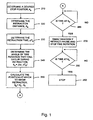
Figure 1 is a flowchart representation of a method for operating a tire uniformity testing machine in accordance with an embodiment of the present invention. - One cause of tire-related nonrepeatability is the common practice of stopping the rotation of the tire to allow for marking, either inside the test zone, or especially, in a following station of the machine. This causes the tire to take a "set", one which will remain even after the tire is brought back to the entrance of the machine to be retested as part of a repeatability test. While it may appear that this is less of a problem to tire manufacturers in terms of their processing of the tire, since all grading decisions have already been made at this time, in many cases, the process flow causes the tire to be routed next to a balance measuring machine [such as an AIT-238 made by ITW Ride Quality Products], where the "set" of the tire may cause incorrect balance measurements and subsequent grading decisions to be made.
- This cause can be overcome by advancing the unloading of the tire so that the load on the tire is removed by the time that the tire is stopped. Those skilled in the art of controlling uniformity machines will understand several ways to implement this control. In this described embodiment, the tire uniformity machine is operated according to a method consisting of the steps outlined in
Figure 1 . A desired stop position is identified instep 210. The distance the loadwheel will need to retract to clear the tire is determined instep 220, based on a measurement of the outside radius of the tire made when the tire was loaded. From this distance and the known rate of motion of the loadwheel carriage, the time needed to retract this distance is calculated instep 230. An angle of tire rotation that will occur during the retraction time is determined instep 240 and a position at which retraction should begin is deduced instep 250. When the tire is in an orientation from which it can be stopped in the time determined in the previous step and result in the tire stopped at the desired location, the loadwheel retract and the stopping of the tire spindle are simultaneously commenced. This causes the loadwheel to release contact with the tire just as the spindle stops (steps 260 - 290). - As can be seen from the foregoing description, by handling the tire during testing in a manner that minimizes the effects of the testing apparatus on the tire's uniformity characteristics, a more repeatable uniformity test can be performed. Although the present invention has been described with a degree of particularity, it is the intent that the invention include all modifications and alterations from the disclosed design falling within the scope of the appended claims.
Claims (2)
- A method for testing a tire comprising the steps of:mounting the tire on a rotatable spindle;applying a load to a tire perimeter with a moveable load carriage by moving the load carriage into contact with the tire perimeter;rotating the tire and measuring one or more tire parameters as a function of the tire's rotational position;determining a desired tire stop position (210);determining a retraction distance (220) that will be traveled by the load carriage to unload the tire;determining a retraction time (230) required for the load carriage to move the retraction distance;calculating an angle of rotation (240) that will occur during the retraction time;deducing a tire retraction position (250) at which retraction must begin such that the load carriage will complete retraction at the desired tire stop position; andbeginning load carriage retraction (270) at the tire retraction position.
- An apparatus for testing a tire comprising:a rotatable spindle for rotating a tire to be tested in a first direction;a load carriage movable along a retraction axis perpendicular to the spindle for contacting the tire being tested, applying a load to the tire, and measuring tire parameters;load cells mounted on the load carriage for measuring radial forces exerted on the load carriage by the tire; anda controller for recording the measured tire parameters as a function of tire rotational position, characterized in that the controller comprises:(i) means for determining a desired tire stop position;(ii) means for determining a retraction distance that will be travelled by the load carriage to unload the tire;(iii) means for determining a retraction time required for the load carriage to move the retraction distance;(iv) means for calculating an angle of rotation that will occur during the retraction time;(v) means for deducing a tire retraction position at which retraction must begin such that the load carriage will complete retraction at the desired tire stop position; and(vi) means for beginning load carriage retraction at the tire retraction position.
Applications Claiming Priority (3)
| Application Number | Priority Date | Filing Date | Title |
|---|---|---|---|
| US37479302P | 2002-04-22 | 2002-04-22 | |
| US10/417,291 US6915684B2 (en) | 2002-04-22 | 2003-04-16 | Tire uniformity testing |
| EP03747042A EP1497633A4 (en) | 2002-04-22 | 2003-04-21 | Improvements in tire uniformity testing |
Related Parent Applications (2)
| Application Number | Title | Priority Date | Filing Date |
|---|---|---|---|
| EP03747042A Division EP1497633A4 (en) | 2002-04-22 | 2003-04-21 | Improvements in tire uniformity testing |
| EP03747042.4 Division | 2003-04-21 |
Publications (2)
| Publication Number | Publication Date |
|---|---|
| EP1624294A1 EP1624294A1 (en) | 2006-02-08 |
| EP1624294B1 true EP1624294B1 (en) | 2010-06-09 |
Family
ID=29219010
Family Applications (2)
| Application Number | Title | Priority Date | Filing Date |
|---|---|---|---|
| EP03747042A Ceased EP1497633A4 (en) | 2002-04-22 | 2003-04-21 | Improvements in tire uniformity testing |
| EP05023215A Expired - Lifetime EP1624294B1 (en) | 2002-04-22 | 2003-04-21 | Tire uniformity testing |
Family Applications Before (1)
| Application Number | Title | Priority Date | Filing Date |
|---|---|---|---|
| EP03747042A Ceased EP1497633A4 (en) | 2002-04-22 | 2003-04-21 | Improvements in tire uniformity testing |
Country Status (14)
| Country | Link |
|---|---|
| US (1) | US6915684B2 (en) |
| EP (2) | EP1497633A4 (en) |
| JP (2) | JP4071720B2 (en) |
| KR (1) | KR20040101402A (en) |
| CN (1) | CN100552406C (en) |
| AT (1) | ATE470845T1 (en) |
| AU (1) | AU2003243148B2 (en) |
| BR (2) | BRPI0309387B1 (en) |
| CA (1) | CA2482473C (en) |
| DE (1) | DE60332969D1 (en) |
| ES (1) | ES2346981T3 (en) |
| MX (1) | MXPA04010529A (en) |
| PT (1) | PT1624294E (en) |
| WO (1) | WO2003089893A1 (en) |
Families Citing this family (13)
| Publication number | Priority date | Publication date | Assignee | Title |
|---|---|---|---|---|
| US8028570B2 (en) * | 2006-02-23 | 2011-10-04 | Seichter Gmbh | Method for testing tires |
| US20090293603A1 (en) * | 2008-05-29 | 2009-12-03 | Michael Wayne Douglas | Method and system for determining wheel parameter consistency |
| JP5776925B2 (en) * | 2010-12-17 | 2015-09-09 | 株式会社ジェイテクト | Rotation angle detector |
| DE112012004163B4 (en) * | 2011-10-06 | 2019-06-27 | Kabushiki Kaisha Kobe Seiko Sho | Tire uniformity tester and tire uniformity test method |
| US9140628B2 (en) * | 2012-02-10 | 2015-09-22 | Akron Special Machinery, Inc. | System for characterizing tire uniformity machines and methods of using the characterizations |
| JP5887224B2 (en) * | 2012-07-20 | 2016-03-16 | 株式会社ブリヂストン | Method and apparatus for measuring tire ground contact characteristics |
| US10514321B2 (en) * | 2013-03-29 | 2019-12-24 | Compagnie Generale Des Etablissements Michelin | Tire uniformity through identification of process effects using regression analysis without azimuth data |
| JP6282198B2 (en) * | 2014-08-27 | 2018-02-21 | 株式会社神戸製鋼所 | Tire uniformity testing machine and tire uniformity measuring method |
| CN114720159A (en) * | 2014-12-05 | 2022-07-08 | 倍耐力轮胎股份公司 | Method and apparatus for inspecting tyres |
| CN104748912B (en) * | 2015-02-04 | 2017-07-25 | 青岛森麒麟轮胎股份有限公司 | A kind of aircraft tyre static balance bearing calibration |
| US9677972B2 (en) | 2015-10-26 | 2017-06-13 | Commercial Time Sharing Inc. | System and method for characterizing tire uniformity machines |
| CN109297731B (en) * | 2018-11-29 | 2021-06-01 | 正新橡胶(中国)有限公司 | Control method and device for tire running test |
| CN113639927A (en) * | 2021-06-15 | 2021-11-12 | 中策橡胶集团有限公司 | Automobile tire flat spot test method, data processing method and equipment |
Family Cites Families (30)
| Publication number | Priority date | Publication date | Assignee | Title |
|---|---|---|---|---|
| DE19639109B4 (en) * | 1996-09-24 | 2008-04-17 | C. Rob. Hammerstein Gmbh & Co. Kg | Longitudinal guide for a vehicle seat with a pair of rails consisting of a seat rail and a bottom rail |
| US3527103A (en) * | 1967-10-30 | 1970-09-08 | Information Dev Corp | Phase angle detector |
| US3752207A (en) | 1969-02-27 | 1973-08-14 | N Branham | Method and apparatus for stabilizing |
| US3844048A (en) | 1969-02-27 | 1974-10-29 | N Branham | Method and apparatus for stabilizing vehicles |
| AT318254B (en) | 1972-12-13 | 1974-10-10 | Heinrich Driendl | Device for displaying the static deformation of vehicle tires |
| US4084350A (en) * | 1974-11-18 | 1978-04-18 | Ongaro Dynamics, Ltd. | Correction of rubber tires for forces generated by dynamic non-uniformities |
| US4112630A (en) * | 1977-08-08 | 1978-09-12 | The Goodyear Tire & Rubber Company | Reduction of lateral force variations of a tire effective in both forward and rearward senses of rotation |
| US4414843A (en) | 1980-09-19 | 1983-11-15 | The Goodyear Tire & Rubber Company | Tire dynamic imbalance screening system |
| DE3041849A1 (en) * | 1980-11-06 | 1982-06-09 | Gebr. Hofmann Gmbh & Co Kg Maschinenfabrik, 6100 Darmstadt | Measuring tyre rolling resistance with radial force suppression - by differencing results obtd. in opposite directions using computer |
| JPS57144442A (en) * | 1981-03-03 | 1982-09-07 | Kobe Steel Ltd | Correction method for measurement error of tire uniformity machine |
| US4704900A (en) * | 1986-08-19 | 1987-11-10 | Eagle-Picher Industries, Inc. | Apparatus and method for imposing a desired average radial force on a tire |
| JP2541981B2 (en) * | 1987-05-20 | 1996-10-09 | 株式会社ブリヂストン | Marking device for tires |
| KR960000995B1 (en) * | 1987-06-12 | 1996-01-15 | 이글 피쳐 인더스트리즈 인코포레이티드 | Apparatus and the method for improving uniformity measurement |
| US4914869A (en) * | 1988-05-16 | 1990-04-10 | General Tire, Inc. | Method for correcting and buffing tires |
| JP2890311B2 (en) * | 1989-02-23 | 1999-05-10 | 横浜ゴム株式会社 | How to measure tire uniformity |
| DE3919450A1 (en) * | 1989-06-14 | 1990-12-20 | Hofmann Gmbh & Co Kg Maschinen | MEASURING DEVICE FOR MEASURING PERIODICALLY CHANGING FORCES AND / OR MOMENTS ON ROTATING ROTORS |
| DE3922288C2 (en) * | 1989-07-06 | 1997-04-10 | Hofmann Gmbh & Co Kg Maschinen | Method and device for checking the uniformity of pneumatic tires, in particular vehicle tires |
| JP2661753B2 (en) * | 1989-08-30 | 1997-10-08 | 株式会社神戸製鋼所 | Tire uniformity machine |
| US5029467A (en) * | 1990-03-12 | 1991-07-09 | Illinois Tool Works, Inc. | Hydraulic apparatus for tire uniformity machine |
| JPH06265444A (en) * | 1993-03-15 | 1994-09-22 | Kobe Steel Ltd | Warming-up characteristic compensating method of tire uniformity machine |
| US5481907A (en) * | 1993-12-13 | 1996-01-09 | Mts Systems Corporation | Tire testing system having focused links reducing cosine errors |
| WO1997028431A1 (en) * | 1996-01-31 | 1997-08-07 | Hunter Engineering Company | Wheel balancer with servo motor |
| EP1019692B1 (en) * | 1996-12-30 | 2002-06-12 | THE GOODYEAR TIRE & RUBBER COMPANY | Methods of adaptive warm-up of force variation machine |
| US6082191A (en) * | 1997-01-24 | 2000-07-04 | Illinois Tool Works, Inc. | Inlet conveyor for tire testing systems |
| US5979231A (en) * | 1997-01-24 | 1999-11-09 | Illinois Tool Works, Inc. | Loadwheel assembly for tire testing systems having conical support plates |
| US6016695A (en) * | 1997-01-24 | 2000-01-25 | Illinois Tool Works Inc. | Tire uniformity testing system |
| US5992227A (en) * | 1997-01-24 | 1999-11-30 | Jellison; Frank R. | Automatic adjustable width chuck apparatus for tire testing systems |
| JP2000241303A (en) * | 1999-02-18 | 2000-09-08 | Kokusai Keisokki Kk | Testing device of tire with wheel |
| JP4964358B2 (en) * | 1999-12-07 | 2012-06-27 | 株式会社デンソー | Rotation sensor detection signal processing apparatus and rotation sensor detection signal output method |
| US6546635B1 (en) * | 2001-09-28 | 2003-04-15 | Hunter Engineering Company | Vehicle service equipment utilizing wheel lateral force measurements |
-
2003
- 2003-04-16 US US10/417,291 patent/US6915684B2/en not_active Expired - Lifetime
- 2003-04-21 DE DE60332969T patent/DE60332969D1/en not_active Expired - Lifetime
- 2003-04-21 MX MXPA04010529A patent/MXPA04010529A/en not_active Application Discontinuation
- 2003-04-21 CA CA002482473A patent/CA2482473C/en not_active Expired - Lifetime
- 2003-04-21 KR KR10-2004-7015924A patent/KR20040101402A/en not_active Application Discontinuation
- 2003-04-21 JP JP2003586578A patent/JP4071720B2/en not_active Expired - Lifetime
- 2003-04-21 BR BRPI0309387-5A patent/BRPI0309387B1/en unknown
- 2003-04-21 EP EP03747042A patent/EP1497633A4/en not_active Ceased
- 2003-04-21 WO PCT/US2003/012199 patent/WO2003089893A1/en active IP Right Grant
- 2003-04-21 CN CNB038085550A patent/CN100552406C/en not_active Expired - Fee Related
- 2003-04-21 ES ES05023215T patent/ES2346981T3/en not_active Expired - Lifetime
- 2003-04-21 AU AU2003243148A patent/AU2003243148B2/en not_active Ceased
- 2003-04-21 PT PT05023215T patent/PT1624294E/en unknown
- 2003-04-21 AT AT05023215T patent/ATE470845T1/en active
- 2003-04-21 EP EP05023215A patent/EP1624294B1/en not_active Expired - Lifetime
- 2003-04-21 BR BRPI0309387-5A patent/BR0309387A/en not_active IP Right Cessation
-
2007
- 2007-11-22 JP JP2007302948A patent/JP2008096451A/en active Pending
Also Published As
| Publication number | Publication date |
|---|---|
| AU2003243148A1 (en) | 2003-11-03 |
| US6915684B2 (en) | 2005-07-12 |
| BR0309387A (en) | 2007-02-21 |
| JP4071720B2 (en) | 2008-04-02 |
| AU2003243148B2 (en) | 2006-02-02 |
| ES2346981T3 (en) | 2010-10-22 |
| JP2008096451A (en) | 2008-04-24 |
| ATE470845T1 (en) | 2010-06-15 |
| WO2003089893A1 (en) | 2003-10-30 |
| JP2006507474A (en) | 2006-03-02 |
| EP1497633A4 (en) | 2006-01-18 |
| PT1624294E (en) | 2010-08-04 |
| CA2482473A1 (en) | 2003-10-30 |
| EP1497633A1 (en) | 2005-01-19 |
| US20030196483A1 (en) | 2003-10-23 |
| CN100552406C (en) | 2009-10-21 |
| CN1646891A (en) | 2005-07-27 |
| DE60332969D1 (en) | 2010-07-22 |
| CA2482473C (en) | 2008-01-29 |
| KR20040101402A (en) | 2004-12-02 |
| MXPA04010529A (en) | 2004-12-13 |
| BRPI0309387B1 (en) | 2017-06-20 |
| EP1624294A1 (en) | 2006-02-08 |
Similar Documents
| Publication | Publication Date | Title |
|---|---|---|
| EP1624294B1 (en) | Tire uniformity testing | |
| US6581448B2 (en) | Snug fitting apparatus for tire assembly and manufacturing method of tire assembly | |
| US3698233A (en) | Apparatus for processing cured tires | |
| US7369956B2 (en) | System for testing tire sidewall irregularities and related methods | |
| US6086452A (en) | Method of high speed centrifugal run-out grinding of a pneumatic tire | |
| CN105910835B (en) | The rim replacing method of tyre tester | |
| US9140628B2 (en) | System for characterizing tire uniformity machines and methods of using the characterizations | |
| US8943881B2 (en) | System for characterizing tire uniformity machines and methods of using the characterizations | |
| US6907781B2 (en) | Wheel balancing system with integrated wheel lift, loaded mode testing, and wheel imaging system | |
| EP2827121B1 (en) | System for characterizing tire uniformity machines and methods of using the characterizations | |
| EP2827120B1 (en) | System for characterizing tire uniformity machines and methods of using the characterizations | |
| AU2006200179B2 (en) | Improvements in tire uniformity testing | |
| WO1998008070A1 (en) | Method of balance screening a pneumatic tire with a tire uniformity machine | |
| JP2792668B2 (en) | Inspection method of tire unevenness by tire uniformity machine | |
| GB2160979A (en) | Automatic machine for checking the rims of disc wheels for motor vehicles | |
| JPS6251735B2 (en) |
Legal Events
| Date | Code | Title | Description |
|---|---|---|---|
| PUAI | Public reference made under article 153(3) epc to a published international application that has entered the european phase |
Free format text: ORIGINAL CODE: 0009012 |
|
| AC | Divisional application: reference to earlier application |
Ref document number: 1497633 Country of ref document: EP Kind code of ref document: P |
|
| AK | Designated contracting states |
Kind code of ref document: A1 Designated state(s): AT BE BG CH CY CZ DE DK EE ES FI FR GB GR HU IE IT LI LU MC NL PT RO SE SI SK TR |
|
| AX | Request for extension of the european patent |
Extension state: AL LT LV MK |
|
| 17P | Request for examination filed |
Effective date: 20060727 |
|
| AKX | Designation fees paid |
Designated state(s): AT BE BG CH CY CZ DE DK EE ES FI FR GB GR HU IE IT LI LU MC NL PT RO SE SI SK TR |
|
| RAP1 | Party data changed (applicant data changed or rights of an application transferred) |
Owner name: MICRO-POISE MEASUREMENT SYSTEMS, LLC |
|
| GRAP | Despatch of communication of intention to grant a patent |
Free format text: ORIGINAL CODE: EPIDOSNIGR1 |
|
| GRAS | Grant fee paid |
Free format text: ORIGINAL CODE: EPIDOSNIGR3 |
|
| GRAA | (expected) grant |
Free format text: ORIGINAL CODE: 0009210 |
|
| AC | Divisional application: reference to earlier application |
Ref document number: 1497633 Country of ref document: EP Kind code of ref document: P |
|
| AK | Designated contracting states |
Kind code of ref document: B1 Designated state(s): AT BE BG CH CY CZ DE DK EE ES FI FR GB GR HU IE IT LI LU MC NL PT RO SE SI SK TR |
|
| REG | Reference to a national code |
Ref country code: CH Ref legal event code: EP |
|
| REG | Reference to a national code |
Ref country code: IE Ref legal event code: FG4D |
|
| REG | Reference to a national code |
Ref country code: NL Ref legal event code: T3 |
|
| REF | Corresponds to: |
Ref document number: 60332969 Country of ref document: DE Date of ref document: 20100722 Kind code of ref document: P |
|
| REG | Reference to a national code |
Ref country code: PT Ref legal event code: SC4A Free format text: AVAILABILITY OF NATIONAL TRANSLATION Effective date: 20100729 |
|
| REG | Reference to a national code |
Ref country code: ES Ref legal event code: FG2A Ref document number: 2346981 Country of ref document: ES Kind code of ref document: T3 |
|
| PG25 | Lapsed in a contracting state [announced via postgrant information from national office to epo] |
Ref country code: SE Free format text: LAPSE BECAUSE OF FAILURE TO SUBMIT A TRANSLATION OF THE DESCRIPTION OR TO PAY THE FEE WITHIN THE PRESCRIBED TIME-LIMIT Effective date: 20100609 |
|
| PG25 | Lapsed in a contracting state [announced via postgrant information from national office to epo] |
Ref country code: SI Free format text: LAPSE BECAUSE OF FAILURE TO SUBMIT A TRANSLATION OF THE DESCRIPTION OR TO PAY THE FEE WITHIN THE PRESCRIBED TIME-LIMIT Effective date: 20100609 |
|
| PG25 | Lapsed in a contracting state [announced via postgrant information from national office to epo] |
Ref country code: CY Free format text: LAPSE BECAUSE OF FAILURE TO SUBMIT A TRANSLATION OF THE DESCRIPTION OR TO PAY THE FEE WITHIN THE PRESCRIBED TIME-LIMIT Effective date: 20100609 Ref country code: GR Free format text: LAPSE BECAUSE OF FAILURE TO SUBMIT A TRANSLATION OF THE DESCRIPTION OR TO PAY THE FEE WITHIN THE PRESCRIBED TIME-LIMIT Effective date: 20100910 |
|
| PG25 | Lapsed in a contracting state [announced via postgrant information from national office to epo] |
Ref country code: EE Free format text: LAPSE BECAUSE OF FAILURE TO SUBMIT A TRANSLATION OF THE DESCRIPTION OR TO PAY THE FEE WITHIN THE PRESCRIBED TIME-LIMIT Effective date: 20100609 |
|
| PG25 | Lapsed in a contracting state [announced via postgrant information from national office to epo] |
Ref country code: SK Free format text: LAPSE BECAUSE OF FAILURE TO SUBMIT A TRANSLATION OF THE DESCRIPTION OR TO PAY THE FEE WITHIN THE PRESCRIBED TIME-LIMIT Effective date: 20100609 Ref country code: RO Free format text: LAPSE BECAUSE OF FAILURE TO SUBMIT A TRANSLATION OF THE DESCRIPTION OR TO PAY THE FEE WITHIN THE PRESCRIBED TIME-LIMIT Effective date: 20100609 Ref country code: CZ Free format text: LAPSE BECAUSE OF FAILURE TO SUBMIT A TRANSLATION OF THE DESCRIPTION OR TO PAY THE FEE WITHIN THE PRESCRIBED TIME-LIMIT Effective date: 20100609 |
|
| PLBE | No opposition filed within time limit |
Free format text: ORIGINAL CODE: 0009261 |
|
| STAA | Information on the status of an ep patent application or granted ep patent |
Free format text: STATUS: NO OPPOSITION FILED WITHIN TIME LIMIT |
|
| PG25 | Lapsed in a contracting state [announced via postgrant information from national office to epo] |
Ref country code: DK Free format text: LAPSE BECAUSE OF FAILURE TO SUBMIT A TRANSLATION OF THE DESCRIPTION OR TO PAY THE FEE WITHIN THE PRESCRIBED TIME-LIMIT Effective date: 20100609 |
|
| 26N | No opposition filed |
Effective date: 20110310 |
|
| REG | Reference to a national code |
Ref country code: DE Ref legal event code: R097 Ref document number: 60332969 Country of ref document: DE Effective date: 20110309 |
|
| PG25 | Lapsed in a contracting state [announced via postgrant information from national office to epo] |
Ref country code: MC Free format text: LAPSE BECAUSE OF NON-PAYMENT OF DUE FEES Effective date: 20110430 |
|
| REG | Reference to a national code |
Ref country code: CH Ref legal event code: PL |
|
| PG25 | Lapsed in a contracting state [announced via postgrant information from national office to epo] |
Ref country code: LI Free format text: LAPSE BECAUSE OF NON-PAYMENT OF DUE FEES Effective date: 20110430 Ref country code: CH Free format text: LAPSE BECAUSE OF NON-PAYMENT OF DUE FEES Effective date: 20110430 |
|
| REG | Reference to a national code |
Ref country code: IE Ref legal event code: MM4A |
|
| PG25 | Lapsed in a contracting state [announced via postgrant information from national office to epo] |
Ref country code: IE Free format text: LAPSE BECAUSE OF NON-PAYMENT OF DUE FEES Effective date: 20110421 |
|
| PG25 | Lapsed in a contracting state [announced via postgrant information from national office to epo] |
Ref country code: BG Free format text: LAPSE BECAUSE OF FAILURE TO SUBMIT A TRANSLATION OF THE DESCRIPTION OR TO PAY THE FEE WITHIN THE PRESCRIBED TIME-LIMIT Effective date: 20100909 |
|
| PG25 | Lapsed in a contracting state [announced via postgrant information from national office to epo] |
Ref country code: HU Free format text: LAPSE BECAUSE OF FAILURE TO SUBMIT A TRANSLATION OF THE DESCRIPTION OR TO PAY THE FEE WITHIN THE PRESCRIBED TIME-LIMIT Effective date: 20100609 |
|
| REG | Reference to a national code |
Ref country code: FR Ref legal event code: PLFP Year of fee payment: 14 |
|
| REG | Reference to a national code |
Ref country code: FR Ref legal event code: PLFP Year of fee payment: 15 |
|
| PGFP | Annual fee paid to national office [announced via postgrant information from national office to epo] |
Ref country code: GB Payment date: 20170427 Year of fee payment: 15 |
|
| PGFP | Annual fee paid to national office [announced via postgrant information from national office to epo] |
Ref country code: BE Payment date: 20170427 Year of fee payment: 15 Ref country code: FI Payment date: 20170427 Year of fee payment: 15 |
|
| REG | Reference to a national code |
Ref country code: FR Ref legal event code: PLFP Year of fee payment: 16 |
|
| REG | Reference to a national code |
Ref country code: BE Ref legal event code: MM Effective date: 20180430 |
|
| GBPC | Gb: european patent ceased through non-payment of renewal fee |
Effective date: 20180421 |
|
| PG25 | Lapsed in a contracting state [announced via postgrant information from national office to epo] |
Ref country code: FI Free format text: LAPSE BECAUSE OF NON-PAYMENT OF DUE FEES Effective date: 20180421 |
|
| PG25 | Lapsed in a contracting state [announced via postgrant information from national office to epo] |
Ref country code: GB Free format text: LAPSE BECAUSE OF NON-PAYMENT OF DUE FEES Effective date: 20180421 Ref country code: BE Free format text: LAPSE BECAUSE OF NON-PAYMENT OF DUE FEES Effective date: 20180430 |
|
| PGFP | Annual fee paid to national office [announced via postgrant information from national office to epo] |
Ref country code: NL Payment date: 20190426 Year of fee payment: 17 Ref country code: LU Payment date: 20190429 Year of fee payment: 17 |
|
| PGFP | Annual fee paid to national office [announced via postgrant information from national office to epo] |
Ref country code: ES Payment date: 20190503 Year of fee payment: 17 Ref country code: PT Payment date: 20190409 Year of fee payment: 17 Ref country code: IT Payment date: 20190423 Year of fee payment: 17 |
|
| PGFP | Annual fee paid to national office [announced via postgrant information from national office to epo] |
Ref country code: FR Payment date: 20190425 Year of fee payment: 17 Ref country code: TR Payment date: 20190412 Year of fee payment: 17 |
|
| PGFP | Annual fee paid to national office [announced via postgrant information from national office to epo] |
Ref country code: AT Payment date: 20190403 Year of fee payment: 17 |
|
| REG | Reference to a national code |
Ref country code: NL Ref legal event code: MM Effective date: 20200501 |
|
| REG | Reference to a national code |
Ref country code: AT Ref legal event code: MM01 Ref document number: 470845 Country of ref document: AT Kind code of ref document: T Effective date: 20200421 |
|
| PG25 | Lapsed in a contracting state [announced via postgrant information from national office to epo] |
Ref country code: AT Free format text: LAPSE BECAUSE OF NON-PAYMENT OF DUE FEES Effective date: 20200421 Ref country code: FR Free format text: LAPSE BECAUSE OF NON-PAYMENT OF DUE FEES Effective date: 20200430 Ref country code: PT Free format text: LAPSE BECAUSE OF NON-PAYMENT OF DUE FEES Effective date: 20201021 Ref country code: LU Free format text: LAPSE BECAUSE OF NON-PAYMENT OF DUE FEES Effective date: 20200421 |
|
| PG25 | Lapsed in a contracting state [announced via postgrant information from national office to epo] |
Ref country code: NL Free format text: LAPSE BECAUSE OF NON-PAYMENT OF DUE FEES Effective date: 20200501 |
|
| REG | Reference to a national code |
Ref country code: ES Ref legal event code: FD2A Effective date: 20210903 |
|
| PG25 | Lapsed in a contracting state [announced via postgrant information from national office to epo] |
Ref country code: IT Free format text: LAPSE BECAUSE OF NON-PAYMENT OF DUE FEES Effective date: 20200421 |
|
| PG25 | Lapsed in a contracting state [announced via postgrant information from national office to epo] |
Ref country code: ES Free format text: LAPSE BECAUSE OF NON-PAYMENT OF DUE FEES Effective date: 20200422 |
|
| PG25 | Lapsed in a contracting state [announced via postgrant information from national office to epo] |
Ref country code: TR Free format text: LAPSE BECAUSE OF NON-PAYMENT OF DUE FEES Effective date: 20200421 |
|
| PGFP | Annual fee paid to national office [announced via postgrant information from national office to epo] |
Ref country code: DE Payment date: 20220427 Year of fee payment: 20 |
|
| REG | Reference to a national code |
Ref country code: DE Ref legal event code: R071 Ref document number: 60332969 Country of ref document: DE |