EP1624261A1 - Engine driven air conditioner and control method therefor - Google Patents
Engine driven air conditioner and control method therefor Download PDFInfo
- Publication number
- EP1624261A1 EP1624261A1 EP05016314A EP05016314A EP1624261A1 EP 1624261 A1 EP1624261 A1 EP 1624261A1 EP 05016314 A EP05016314 A EP 05016314A EP 05016314 A EP05016314 A EP 05016314A EP 1624261 A1 EP1624261 A1 EP 1624261A1
- Authority
- EP
- European Patent Office
- Prior art keywords
- bypass valve
- pressure difference
- engine
- entrance
- valve
- Prior art date
- Legal status (The legal status is an assumption and is not a legal conclusion. Google has not performed a legal analysis and makes no representation as to the accuracy of the status listed.)
- Granted
Links
Images


Classifications
-
- F—MECHANICAL ENGINEERING; LIGHTING; HEATING; WEAPONS; BLASTING
- F25—REFRIGERATION OR COOLING; COMBINED HEATING AND REFRIGERATION SYSTEMS; HEAT PUMP SYSTEMS; MANUFACTURE OR STORAGE OF ICE; LIQUEFACTION SOLIDIFICATION OF GASES
- F25B—REFRIGERATION MACHINES, PLANTS OR SYSTEMS; COMBINED HEATING AND REFRIGERATION SYSTEMS; HEAT PUMP SYSTEMS
- F25B27/00—Machines, plants or systems, using particular sources of energy
-
- F—MECHANICAL ENGINEERING; LIGHTING; HEATING; WEAPONS; BLASTING
- F25—REFRIGERATION OR COOLING; COMBINED HEATING AND REFRIGERATION SYSTEMS; HEAT PUMP SYSTEMS; MANUFACTURE OR STORAGE OF ICE; LIQUEFACTION SOLIDIFICATION OF GASES
- F25B—REFRIGERATION MACHINES, PLANTS OR SYSTEMS; COMBINED HEATING AND REFRIGERATION SYSTEMS; HEAT PUMP SYSTEMS
- F25B27/00—Machines, plants or systems, using particular sources of energy
- F25B27/02—Machines, plants or systems, using particular sources of energy using waste heat, e.g. from internal-combustion engines
-
- B—PERFORMING OPERATIONS; TRANSPORTING
- B60—VEHICLES IN GENERAL
- B60H—ARRANGEMENTS OF HEATING, COOLING, VENTILATING OR OTHER AIR-TREATING DEVICES SPECIALLY ADAPTED FOR PASSENGER OR GOODS SPACES OF VEHICLES
- B60H1/00—Heating, cooling or ventilating devices
- B60H1/32—Cooling devices
- B60H1/3204—Cooling devices using compression
- B60H1/3205—Control means therefor
-
- B—PERFORMING OPERATIONS; TRANSPORTING
- B60—VEHICLES IN GENERAL
- B60H—ARRANGEMENTS OF HEATING, COOLING, VENTILATING OR OTHER AIR-TREATING DEVICES SPECIALLY ADAPTED FOR PASSENGER OR GOODS SPACES OF VEHICLES
- B60H1/00—Heating, cooling or ventilating devices
- B60H1/32—Cooling devices
- B60H1/3204—Cooling devices using compression
- B60H1/3225—Cooling devices using compression characterised by safety arrangements, e.g. compressor anti-seizure means or by signalling devices
-
- F—MECHANICAL ENGINEERING; LIGHTING; HEATING; WEAPONS; BLASTING
- F24—HEATING; RANGES; VENTILATING
- F24F—AIR-CONDITIONING; AIR-HUMIDIFICATION; VENTILATION; USE OF AIR CURRENTS FOR SCREENING
- F24F5/00—Air-conditioning systems or apparatus not covered by F24F1/00 or F24F3/00, e.g. using solar heat or combined with household units such as an oven or water heater
-
- F—MECHANICAL ENGINEERING; LIGHTING; HEATING; WEAPONS; BLASTING
- F25—REFRIGERATION OR COOLING; COMBINED HEATING AND REFRIGERATION SYSTEMS; HEAT PUMP SYSTEMS; MANUFACTURE OR STORAGE OF ICE; LIQUEFACTION SOLIDIFICATION OF GASES
- F25B—REFRIGERATION MACHINES, PLANTS OR SYSTEMS; COMBINED HEATING AND REFRIGERATION SYSTEMS; HEAT PUMP SYSTEMS
- F25B30/00—Heat pumps
-
- F—MECHANICAL ENGINEERING; LIGHTING; HEATING; WEAPONS; BLASTING
- F25—REFRIGERATION OR COOLING; COMBINED HEATING AND REFRIGERATION SYSTEMS; HEAT PUMP SYSTEMS; MANUFACTURE OR STORAGE OF ICE; LIQUEFACTION SOLIDIFICATION OF GASES
- F25B—REFRIGERATION MACHINES, PLANTS OR SYSTEMS; COMBINED HEATING AND REFRIGERATION SYSTEMS; HEAT PUMP SYSTEMS
- F25B49/00—Arrangement or mounting of control or safety devices
-
- F—MECHANICAL ENGINEERING; LIGHTING; HEATING; WEAPONS; BLASTING
- F25—REFRIGERATION OR COOLING; COMBINED HEATING AND REFRIGERATION SYSTEMS; HEAT PUMP SYSTEMS; MANUFACTURE OR STORAGE OF ICE; LIQUEFACTION SOLIDIFICATION OF GASES
- F25B—REFRIGERATION MACHINES, PLANTS OR SYSTEMS; COMBINED HEATING AND REFRIGERATION SYSTEMS; HEAT PUMP SYSTEMS
- F25B49/00—Arrangement or mounting of control or safety devices
- F25B49/005—Arrangement or mounting of control or safety devices of safety devices
-
- B—PERFORMING OPERATIONS; TRANSPORTING
- B60—VEHICLES IN GENERAL
- B60H—ARRANGEMENTS OF HEATING, COOLING, VENTILATING OR OTHER AIR-TREATING DEVICES SPECIALLY ADAPTED FOR PASSENGER OR GOODS SPACES OF VEHICLES
- B60H1/00—Heating, cooling or ventilating devices
- B60H1/32—Cooling devices
- B60H2001/3236—Cooling devices information from a variable is obtained
- B60H2001/3248—Cooling devices information from a variable is obtained related to pressure
- B60H2001/325—Cooling devices information from a variable is obtained related to pressure of the refrigerant at a compressing unit
-
- B—PERFORMING OPERATIONS; TRANSPORTING
- B60—VEHICLES IN GENERAL
- B60H—ARRANGEMENTS OF HEATING, COOLING, VENTILATING OR OTHER AIR-TREATING DEVICES SPECIALLY ADAPTED FOR PASSENGER OR GOODS SPACES OF VEHICLES
- B60H1/00—Heating, cooling or ventilating devices
- B60H1/32—Cooling devices
- B60H2001/3269—Cooling devices output of a control signal
- B60H2001/327—Cooling devices output of a control signal related to a compressing unit
-
- F—MECHANICAL ENGINEERING; LIGHTING; HEATING; WEAPONS; BLASTING
- F25—REFRIGERATION OR COOLING; COMBINED HEATING AND REFRIGERATION SYSTEMS; HEAT PUMP SYSTEMS; MANUFACTURE OR STORAGE OF ICE; LIQUEFACTION SOLIDIFICATION OF GASES
- F25B—REFRIGERATION MACHINES, PLANTS OR SYSTEMS; COMBINED HEATING AND REFRIGERATION SYSTEMS; HEAT PUMP SYSTEMS
- F25B13/00—Compression machines, plants or systems, with reversible cycle
-
- F—MECHANICAL ENGINEERING; LIGHTING; HEATING; WEAPONS; BLASTING
- F25—REFRIGERATION OR COOLING; COMBINED HEATING AND REFRIGERATION SYSTEMS; HEAT PUMP SYSTEMS; MANUFACTURE OR STORAGE OF ICE; LIQUEFACTION SOLIDIFICATION OF GASES
- F25B—REFRIGERATION MACHINES, PLANTS OR SYSTEMS; COMBINED HEATING AND REFRIGERATION SYSTEMS; HEAT PUMP SYSTEMS
- F25B2327/00—Compressor driving means
-
- F—MECHANICAL ENGINEERING; LIGHTING; HEATING; WEAPONS; BLASTING
- F25—REFRIGERATION OR COOLING; COMBINED HEATING AND REFRIGERATION SYSTEMS; HEAT PUMP SYSTEMS; MANUFACTURE OR STORAGE OF ICE; LIQUEFACTION SOLIDIFICATION OF GASES
- F25B—REFRIGERATION MACHINES, PLANTS OR SYSTEMS; COMBINED HEATING AND REFRIGERATION SYSTEMS; HEAT PUMP SYSTEMS
- F25B2600/00—Control issues
- F25B2600/02—Compressor control
- F25B2600/026—Compressor control by controlling unloaders
- F25B2600/0261—Compressor control by controlling unloaders external to the compressor
Definitions
- the present invention relates to an engine driving type air conditioner equipped with an outdoor unit having a compressor driven by an engine and an outdoor heat exchanger and an indoor unit having an indoor heat exchanger and a method of controlling the air conditioner, and also to detection of a bypass valve provided in a bypass pipe through which a part of refrigerant discharged from the compressor is returned to the suction side of the compressor.
- the bypass valve is locked because it bites dust or it is damaged.
- the rotational number of the engine is controlled to be set to a higher value than a normal rotational number in order to secure a predetermined refrigerant circulation amount, so that the fuel consumption amount is increased.
- an obj ect of the present invention is to provide an engine driving type air conditioner that can detect the lock of a bypass valve, and a method of controlling the air conditioner.
- an engine driving type air conditioner including an outdoor unit having a compressor driven by an engine and a indoor unit which are connected to each other through a refrigerant pipe, the outdoor unit having a bypass pipe for returning a part of refrigerant discharged from the compressor to the suction side of the compressor and a bypass valve provided in the bypass pipe, is characterized by comprising: a bypass valve abnormality detecting unit for controlling the bypass valve so that the bypass valve is subjected to a valve opening/closing operation when the engine is stopped, detecting the pressure difference of refrigerant between both the entrance and exit sides of the bypass valve in a predetermined time after the bypass valve is subjected to the valve opening/closing operation, and judging on the basis of a detection result concerning the pressure difference whether the bypass valve is locked or not.
- the bypass valve abnormality detecting unit controls the bypass valve so that the bypass valve is closed when the engine is stopped, detecting the pressure difference of the refrigerant between both the entrance and exit sides of the bypass valve after a predetermined time elapses from the time when the bypass valve is closed, and judging whether the pressure difference concerned is within a predetermined range, thereby judging whether the bypass valve is open-locked or not.
- the bypass valve abnormality detecting unit judges whether the bypass valve is open-locked, on the basis of the difference of the pressure difference between both the entrance and exit sides of the bypass valve after the predetermined time elapses and the pressure difference between both the entrance and exit sides of the bypass valve which is detected in advance before the engine is driven.
- the bypass valve abnormality detecting unit determines a first variation degree of the pressure difference between both the entrance and exit sides of the bypass valve when the engine is stopped and the bypass valve is closed, and a second variation degree of the pressure difference between both the entrance and exit sides of the bypass valve when the bypass valve is opened again after the bypass valve is closed, compares the first and second variation degrees and judges on the basis of the comparison result whether the bypass valve is close-locked or not.
- the above engine driving type air conditioner further comprises an alarm unit for alarming the lock of the bypass valve when the bypass valve abnormality detecting unit detects the lock of the bypass valve.
- the above engine driving type air conditioner further comprises a storage unit for storing operation data of the engine driving type air conditioner when the bypass valve abnormality detecting unit detects the lock of the bypass valve, and a display unit for displaying the operation data stored in the storage unit.
- a method of controlling an engine driving type air conditioner including an outdoor unit having a compressor driven by an engine and a indoor unit which are connected to each other through a refrigerant pipe, the outdoor unit having a bypass pipe for returning a part of refrigerant discharged from the compressor to the suction side of the compressor and a bypass valve provided in the bypass pipe, is characterized by comprising the steps of: controlling the bypass valve so that the bypass valve is subjected to a valve opening/closing operation when the engine is stopped; detecting the pressure difference of refrigerant between both the entrance and exit sides of the bypass valve in a predetermined time after the bypass valve is subjected to the valve opening/closing operation; and judging on the basis of a detection result concerning the pressure difference whether the bypass valve is locked or not.
- the controlling step comprises a step of closing the bypass valve when the engine is stopped, detecting the pressure difference of the refrigerant between both the entrance and exit sides of the bypass valve after a predetermined time elapses from the time when the bypass valve is closed, and judging whether the pressure difference concerned is within a predetermined range, thereby judging whether the bypass valve is open-locked or not.
- the judging step comprises a step of determining a first variation degree of the pressure difference between both the entrance and exit sides of the bypass valve when the engine is stopped and the bypass valve is closed, and a second variation degree of the pressure difference between both the entrance and exit sides of the bypass valve when the bypass valve is opened again after the bypass valve is closed, comparing the first and second variation degrees and judging on the basis of the comparison result whether the bypass valve is close-locked or not.
- the above method further comprises a step of alarming the lock of the bypass valve when the bypass valve abnormality detecting unit detects the lock of the bypass valve.
- the bypass valve when the engine is stopped, the bypass valve is closed, the pressure difference of the refrigerant between the entrance and exit sides of the bypass valve after a predetermined time elapses is detected, and it is judged whether the pressure difference is within a predetermined range, whereby it is judged whether the bypass valve is open-locked. Therefore, the open-lock state of the bypass valve can be detected with high precision. Furthermore, when the engine is stopped, the bypass valve is closed, and the variation degree of the pressure difference between the entrance and exit sides of the bypass valve is calculated. Thereafter, the bypass valve is opened, the variation degree of the pressure difference between the entrance and exist sides of the bypass valve is calculated, and these variation degrees thus calculated are compared with each other. By judging whether the comparison result is within a predetermined range, it is detected whether the bypass valve is close-locked or not. Therefore, the close-lock state of the bypass valve can be detected with high precision.
- Fig. 1 is a diagram showing the construction of an engine driving type air conditioner 100 according to an embodiment of the present invention.
- Te engine driving type air conditioner 100 includes an outdoor unit 1, a plurality of (for example, two) indoor units 2a, 2b, and a refrigerant pipe (inter-unit pipe) 3 comprising a gas pipe 3a and a liquid pipe 3b through which the outdoor unit 1 is connected to the indoor units 2a, 2b.
- the engine driving type air conditioner 100 is equipped with a control device 4 for controlling the driving operation of the air conditioner 100 and an operating unit 5 for carrying out operations such as a driving instruction of the control device 4, etc.
- the operating unit 5 includes an operating panel for operating/stopping the indoor units 2a, 2b, etc., and a display panel (display unit) for displaying various settings and the operation state of the indoor units 2a, 2b and the outdoor unit 1.
- the engine driving type air conditioner 100 is designed so that alternative refrigerant R410a having high refrigerant capability per unit volume and small pressure loss is circulated therein.
- the outdoor unit 1 is disposed outdoors.
- an engine 10 for combusting fuel gas or the like to generate driving force
- a compressor 11 connected through a driving force transmitting unit (not shown) to the engine 10 to compress and discharge the alternative refrigerant R410a
- a four-way valve 12 for inverting the circulation direction of the refrigerant
- an outdoor heat exchanger 13 for carrying out the heat exchange between the refrigerant and the outside air
- an outdoor expansion valve 14 for reducing the pressure of the refrigerant
- an accumulator for carrying out gas-liquid separation of the refrigerant to be sucked into the compressor 11, these elements being connected to one another through the refrigerant pipe.
- an outdoor fan 16 for blowing air to the outdoor heat exchanger 13 is disposed in proximity to the outdoor heat exchanger 13.
- a bypass pipe 17 is connected between a refrigerant high-pressure side (the discharge side of the compressor 11) and a refrigerant low-pressure side (the entrance side of the accumulator 15 in Fig. 1), and a bypass valve (electrically-operated valve) 18 is provided in the bypass pipe 17.
- a bypass valve electrically-operated valve 18
- the bypass valve 18 is opened to reduce the compression ratio of the compressor 11, and thus the load of the engine 10 can be reduced.
- a pressure sensor (not shown) is provided to each of the refrigerant high pressure side and the refrigerant low pressure side, and the pressure values of the refrigerant at both the entrance and exit sides of the bypass valve 18 are detected by these pressure sensors.
- the outdoor unit 1 is provided with a liquid pipe 40 for suitably supplying liquid refrigerant flowing through a pipe (liquid pipe) 19 at the outdoor unit 1 side to the entrance side of the accumulator 15 provided at the suction side of the compressor 11, and a liquid valve (electrically operated valve) 41 is provided in the liquid pipe 40.
- a liquid pipe 40 for suitably supplying liquid refrigerant flowing through a pipe (liquid pipe) 19 at the outdoor unit 1 side to the entrance side of the accumulator 15 provided at the suction side of the compressor 11, and a liquid valve (electrically operated valve) 41 is provided in the liquid pipe 40.
- the liquid valve 4 is normally closed, however, when the temperature of the refrigerant discharged from the compressor 11 exceeds a predetermined temperature (this temperature is varied in accordance with the type of the refrigerant, however, it is set to 115°C or the like), the liquid valve 41 is opened to supply the low-temperature liquid refrigerant from the pipe 19 at the outdoor unit 1 side to the entrance side of the accumulator 15, whereby the temperature of the gas refrigerant sucked into the compressor 11 is lowered and the overheat of the refrigerant discharged from the compressor 11 can be prevented.
- a predetermined temperature this temperature is varied in accordance with the type of the refrigerant, however, it is set to 115°C or the like
- the indoor unit 2a, 2b is equipped with an indoor heat exchanger 20a, 20b for carrying out the heat exchange between the refrigerant and indoor air in a room in which the indoor unit 2a, 2b is secured, and an indoor expansion valve 21a, 21b for controlling the refrigerant amount of the refrigerant flowing into the indoor unit 2a, 2b, the indoor heat exchangers 20a, 20b and the indoor expansion valves 21a, 21b being connected to one another through the refrigerant pipe. Furthermore, an indoor fan 22a, 22b for blowing air to the indoor heat exchanger 20a, 20 is disposed in proximity to the indoor heat exchanger 20a, 20b.
- air-fuel mixture is supplied from an engine fuel supply device 31 into the combustion chamber of the engine 10 for driving the compressor 11.
- the engine fuel supply device 31 includes fuel cutoff valves 33, a zero governor 34, a fuel adjusting valve 35 and a throttle valve 36 which are successively disposed in a fuel supply pipe 32 in this order, and the throttle valve 36 is connected to the combustion chamber of the engine 10.
- the fuel cutoff valves 33 constitute a close type fuel cutoff valve mechanism, and one of the cutoff of the fuel gas with no leakage and the intercommunication of the fuel gas is selectively performed by fully closing or opening the fuel cutoff valves 33.
- Fig. 2 is a block diagram showing the construction of a control device 4.
- the control device 4 is equipped with a setting unit 47 for setting a driving instruction, etc. to the engine 10 and the compressor 11, EEPROM (storage unit) 42 for storing various kinds of setting data of the engine driving type air conditioner 100, control programs and control data, etc., CPU 43 for controlling the whole of the engine driving type air conditioner 100 on the basis of the control programs, etc. stored in EEPROM 42, RAM 44 for temporarily storing various kinds of data, a transceiver 45 for making communications with the operating unit 5, and an interface (I/F) 46 for transmitting/receiving signals to/from the respective units of the engine driving type air conditioner 100.
- EEPROM storage unit
- CPU 43 for controlling the whole of the engine driving type air conditioner 100 on the basis of the control programs, etc. stored in EEPROM 42
- RAM 44 for temporarily storing various kinds of data
- transceiver 45 for making communications with the operating unit 5
- an interface (I/F) 46 for transmitting/
- the control device 4 is further connected through the I/F 46 to a rotational number detector (not shown) for detecting the rotational number of the engine 10, and temperature sensors (an indoor temperature sensor for measuring the indoor temperature (not shown), temperature sensors for measuring the refrigerant temperature at the inlet/outlet ports of each of the heat exchangers 13, 20a, 20b (not shown), and temperature sensors 23a, 23b for measuring the air blow-out temperature of the indoor fans 22a, 22b of the indoor units 2a, 2b (not shown)), and it is designed so as to achieve the information on the rotational number of the engine and the temperature at each place.
- the control device 4 is connected to pressure sensors for detecting the pressure values of the refrigerant at the entrance and exit of the bypass valve 18, and the pressure difference ⁇ P between the entrance and exit sides of the bypass pipe 18 can be achieved by these sensors.
- control device 4 controls each of the engine 10, the four-way valve 12, the outdoor expansion valve 14 and the outdoor fan 16 of the outdoor unit 1 and the indoor expansion valves 21a, 21b and the indoor fans 22a, 22b of the indoor units 2a, 2b.
- the control device 4 switches the four-way valve 12 to set the air conditioner 1 to cooling operation or heating operation. That is, when the four-way valve 12 is switched to the cooling side, the refrigerant flows as indicated by a broken-line arrow, the outdoor heat exchanger 13 functions as a condenser and the indoor heat exchangers 20a, 20b function as evaporators, so that the operation state of the air conditioner is set to a cooling operation state and each of the indoor heat exchangers 20a, 20b cools a room.
- the refrigerant flows as indicated by a solid-line arrow
- the indoor heat exchangers 20a, 20b function as condensers
- the outdoor heat exchanger 13 functions as an evaporator, so that the operation state of the air conditioner is set to a heating operation state and each of the indoor heat exchangers heats a room.
- control device 4 controls the opening degrees of the fuel adjusting valve 35 and throttle valve 36 (the fuel adjusting valve opening degree, the throttle opening degree) on the basis of the difference between the set temperature set by the operating unit 5 and the indoor temperature achieved from the indoor temperature sensor, etc. to variably control the rotational number of the engine 10, and also controls the opening degree of the bypass valve.
- control device 4 controls the opening degrees of the outdoor expansion valve 14 and indoor expansion valves 21a, 21b on the basis of the refrigerant temperature difference between the refrigerant inlet/outlet ports of the heat exchangers 13, 20a, 20b.
- control device 4 carries out bypass valve abnormality detection processing of detecting whether the bypass valve 18 is locked or not.
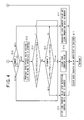
- Figs. 3 and 4 are flowcharts showing the bypass valve abnormality detection processing
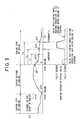
- Fig. 5 is a diagram showing the variation characteristic of the pressure difference ⁇ P between the entrance and exit sides of the bypass valve 18 and the opening degree of the bypass valve 18 in the same time sequence.
- control device 4 detects the pressure values at both the entrance and exit sides of the bypass valve 18 by the pressure sensors, and achieves the pressure difference ⁇ P between the entrance and exit sides of the bypass valve 18 when the engine 10 is started (step S1).
- this engine driving type air conditioner 100 is one of some types of air conditioners (for example, old types or the like) in which the pressure sensor for detecting the pressure at the low pressure side (the entrance side of the accumulator 15) is over range and thus it is impossible to detect abnormality of the bypass valve 18 with high precision even when the bypass valve abnormality detection processing is carried out
- the control device 4 judges whether the pressure at the low pressure side achieved when the pressure difference ⁇ P is achieved is not less than a predetermined pressure PA (step S2). If the judgment of the step S2 is positive (step S2: Y (over range)), the control device 4 shifts to step S17 to cancel the bypass valve abnormality detection processing.
- step S3 the control device 4 carries out error correction on the pressure sensor (step S3). Specifically, it is expected that the pressure values at the entrance and exit sides of the bypass valve 18 are substantially equal to each other before the engine 10 is started, and thus the pressure difference ⁇ P is substantially equal to zero. Therefore, when the pressure difference ⁇ P0 achieved is equal to or more than a positive value +X near to zero (for example, 0.05), that is, the measurement value is shifted to a positive side, the control device 4 sets the pressure difference ⁇ P0 to +X.
- a positive value +X near to zero for example, 0.05
- the control device 4 sets the pressure difference ⁇ P0 to -X.
- the control device 4 shifts to an engine driving state (during complete explosion). It checks a lock counter value which wouldbe counted up in the processing described later if there is any doubt that the bypass valve 18 is locked, and judges whether the lock counter value is equal to a predetermined number (5 in the example of the figure) or more (step S4).
- This lock counter value is stored in a predetermined area of RAM 44.
- the control device 4 carries out alarm processing of alarming that there is some abnormality in the bypass valve 18, and then clears the lock counter value to zero (step S5).
- this alarm processing is carries out by displaying a predetermined error code on a display panel of the operating unit 5 or emitting a predetermined warning sound with a sound emitting unit such as a buzzer or the like.
- step S6 the control device 4 judges whether the engine 10 is under driving (under complete explosion) (step S6). If the engine 10 is under complete explosion (step S6: Y), upon input of an engine stop instruction from the operating unit, the control device 4 achieves the pressure difference ⁇ P1 at both the entrance and exit sides of the bypass valve 18 (Fig. 4) just before the engine is stopped (step S7), and then stops the engine 10.
- step S8 judges whether the present situation corresponds to a condition inadequate to the detection of abnormality of the bypass vale 18 (detection inadequacy condition described later) (step S8).
- the control device 4 shifts to step S17 to cancel the bypass valve abnormality detection processing.
- the control device 4 controls the bypass valve 18 so that the bypass valve 18 is kept to the close state (for example, the opening degree of the bypass valve 18 is set to 20 steps).
- the detection inadequacy condition may be used a condition that the pressure values at both the entrance and exit sides of the bypass valve 18 is estimated to reach pressure equalization to each other more early than normally expected, etc.
- this embodiment adopts, as the detection inadequacy condition, (1) the bypass valve 18 is kept opened by about a half or more (for example, the opening degree of the bypass valve 18 > 200 steps), (2) there is little difference between the pressure difference ⁇ P1 and the pressure difference ⁇ P0 (for example, ⁇ P1 ⁇ ⁇ P0 + k0 (K0 represents a predetermined value)) , (3) the liquid valve 41 is kept opened by about a half or more (for example, the opening degree of the liquid valve 41 ⁇ 200 steps), (4) the maximum opening degree of the indoor expansion valve 21a, 21b is large during cooling operation (for example, the opening degree of the indoor expansion valve ⁇ 300 steps), (5) The maximum opening degree of the outdoor expansion valve 14 is large during heating operation (for example, the opening degree of the outdoor expansion valve ⁇ 300 steps),
- step S8 If any one of the above detection inadequacy conditions is satisfied (step S8 : Y), the control device 4 shifts to step S17 to cancel the bypass valve abnormality detection processing. On the other hand, if any one of the detection inadequacy conditions is not satisfied (step S8: N), the control device 4 achieves information on the pressure difference ⁇ P3 of the refrigerant in the bypass pipe 17 at the time point when a predetermined time T1 has elapsed from the stop of the engine and the pressure difference ⁇ P2 of the refrigerant in the bypass pipe 17 at the time point when a predetermined time T2 (T2 > T1) has elapsed (step S9).
- the pressure values at the entrance and exit sides of the bypass valve 18 are gradually equal to each other, and thus the pressure difference ⁇ P at both the entrance and exit sides of the bypass valve 18 gradually approaches to zero as shown in Fig. 5.
- the times T1 and T2 are set so that these times T1 and T2 have elapsed before the pressure equalization is completed and also they avoid a peculiar area (indicated by ⁇ in Fig. 5) in which the pressure difference ⁇ P of the bypass pipe 17 is rapidly varied just after the engine is stopped.
- the control device 4 subtracts the pressure difference ⁇ P0 from the pressure difference ⁇ P2, and judges an open-lock judgment (judgment 1) of the bypass valve 18 on the basis of the subtraction value (step S10). Specifically, when the subtraction value is equal to or less than the lower limit value K1 of the difference between the pressure difference ⁇ P2 and the pressure difference ⁇ P0 existing when the bypass valve 18 is normal (step S10: ⁇ K1), it is judged that the bypass valve 18 may be under non-closed state, that is, it may be open-locked with high probability.
- the control device 4 increments the lock counter value by only 1, and stores the operation data (for example, the measurement values of the respective sensors such as the pressure differences P0 to P3, etc.) as abnormality record information in EEPROM 42 (step S11).
- the abnormality record information (operation data) stored in EEPROM 42 is displayed on the display panel of the operating unit 5 by the control device 4 in response to the operation of the operating unit 5 or the like. Accordingly, users can be provided with information available to specify an abnormality place or the like.
- the pressure difference ⁇ P2 at a predetermined time point until the pressure values at the entrance and exit sides of the bypass valve 18 are equal to each other is achieved (pressure equalization is completed, and it is judged whether the difference between the pressure difference ⁇ P2 thus achieved and the pressure difference ⁇ P0 measured in advance when the pressure equalization is completed is within a predetermined range, whereby it can be detected with high precision whether the pressure equalizing speed is higher than a normal speed, that is, the bypass valve 18 is open-locked.
- step S10 ⁇ K2
- step S10 ⁇ K2
- the control device 4 shifts to detection processing of close-lock (steps S12 to S14) .
- step S10 Else
- the control device 4 shifts to step S15 without carrying out the detection processing (steps S12 to S14) of the close-lock, and clears the lock counter value to zero.
- the control device 4 first controls the bypass valve 18 from the close state (fully-closed state) to the open state (fully-opened state), and achieves a pressure difference ⁇ P4 at both the entrance and exit sides of the bypass valve 18 at the time point when a predetermined time T3 has elapsed from the stop of the engine (step S12) as shown in Fig. 5.
- the bypass valve 18 is normally switched to the open state, the pressure equalization speed of the pressure at both the entrance and exit sides of the bypass valve 18 is increased.
- the time T3 it is set to a time point before the pressure values at both the entrance and exit sides of the bypass valve 18 are substantially equal to each other (the point T4 shown in Fig. 5).
- control device 4 calculates the subtraction value achieved by subtracting the pressure difference ⁇ P4 from the pressure difference ⁇ P2 thus achieved and also the subtraction value achieved by subtracting the pressure difference ⁇ P2 from the pressure difference ⁇ P3, and judges whether these subtraction values are equal to zero or less (step S13). If both the subtraction values are not equal to zero or the like (step S13: N), a close-lock judgment (judgment 2) of the bypass valve 18 is carried out (step S14). If anyone of the subtraction values is equal to zero or less (step S13: Y), the control device 4 shifts to step S15 to clear the lock counter value to zero.
- the close-lock judgment (judgment 2) of the bypass valve 18 is carried out by comparing the subtraction value between the pressure difference ⁇ P2 and the pressure difference ⁇ P4 and the subtraction value between the pressure difference ⁇ P3 and the pressure difference ⁇ P2 (step S14).
- the control device 4 calculates the ratio Z of the variation degree.
- the control device 4 calculates the division value of the subtraction value between the pressure difference ⁇ P2 and the pressure difference ⁇ P4 and the subtraction value between the pressure difference ⁇ P3 and the pressure difference ⁇ P2, and multiplies the division value by a coefficient K3 to calculate a value Z.
- the coefficient K3 represents a coefficient for matching the time among the variation degrees, and specifically, it is calculated from (T3-T2)/(T2-T1). Accordingly, the control device 4 calculates the value Z indicating the ratio between the pressure equalization speed under the bypass valve closing control and the pressure equalization speed under the bypass valve opening control.
- step S14 Z ⁇ 2
- the control device 4 judges that the bypass valve 18 is normal, and then shifts to step S16 to clear the lock counter value to zero.
- the control device 4 does not carry out the bypass valve abnormality detection processing until the date is changed.
- step S14 if the value Z is not more than 1 (step S14: Z ⁇ 1), it indicates that the pressure equalization speed under the bypass valve closing control is higher than the pressure equalization speed under the bypass valve opening control, and thus it is judged that there is a doubt that the bypass valve 18 is close-locked, and thus the control device 4 shifts to step S11 .
- the control device increments the lock counter value by only 1, and also stores the operation data at this time into EEPROM 42.
- step S14 Else
- the control device 4 clears the lock counter value to zero when the date is changed (step S17) or keeps the lock counter value unchanged before the date is changed, and returns the processing to the processing of step S1. Accordingly, the control device 4 repetitively carries out the bypass valve abnormality detection processing, and increments the lock counter value every time it is judged through the judgment 1 and the judgment 2 whether there is a doubt that the bypass valve 18 is locked. At the time point when the count value exceeds a predetermined number (5 in this embodiment), the control device 4 carries out the alarm processing and alarms that there is abnormality in the bypass valve 18.
- the bypass valve 18 is controlled to be closed.
- the pressure difference ⁇ 2 of the refrigerant between both the entrance and exit sides of the bypass valve 18 is achieved at a predetermined time point before the pressure values at both the entrance and exit sides of the bypass valve 18 are equal to each other, and by judging whether the pressure difference ⁇ P2 is within a normal range, it can be detected with high precision whether the bypass valve 18 is open-locked or not.
- the bypass valve 18 is switched from the closing control to the opening control, the variation degree of the pressure difference ⁇ P at both the entrance and exit sides of the bypass valve 18 (the pressure difference ⁇ P3 - ⁇ P2) under the bypass valve closing control is compared with the variation degree of the pressure difference ⁇ P at both the entrance and exit sides of the bypass valve 18 (the pressure difference ⁇ P2 - ⁇ P40) under the bypass valve opening control, and it is judged whether the comparison result is within a normal range, whereby it can be detected with high precision whether the bypass valve 18 is close-locked or not.
- the present invention is not limited to the above embodiment, and for example, the setting values and the pipe construction of the above embodiment may be changed without departing the subject matter of the present invention.
- the abnormality (lock) of the bypass valve 18 is detected by using the information on the pressure difference between the entrance and exit sides of the bypass valve 18 or the variation degree of the pressure difference.
- the abnormality (lock) of the bypass valve 18 may be detected when the opening degree of the liquid valve 41 is equal to a predetermined opening value or less.
Landscapes
- Engineering & Computer Science (AREA)
- Mechanical Engineering (AREA)
- Physics & Mathematics (AREA)
- Thermal Sciences (AREA)
- General Engineering & Computer Science (AREA)
- Chemical & Material Sciences (AREA)
- Combustion & Propulsion (AREA)
- Life Sciences & Earth Sciences (AREA)
- Sustainable Development (AREA)
- Air Conditioning Control Device (AREA)
- Other Air-Conditioning Systems (AREA)
Abstract
Description
- The present invention relates to an engine driving type air conditioner equipped with an outdoor unit having a compressor driven by an engine and an outdoor heat exchanger and an indoor unit having an indoor heat exchanger and a method of controlling the air conditioner, and also to detection of a bypass valve provided in a bypass pipe through which a part of refrigerant discharged from the compressor is returned to the suction side of the compressor.
- There has been known a so-called engine driving type air conditioner in which a compressor of an outdoor unit is driven by an engine using gas or the like as fuel to compress and circulate refrigerant. This type of engine driving type air conditioner is equipped with a bypass pipe for returning a part of the refrigerant discharged from the compressor to the suction side of the compressor in some cases. In this case, a bypass valve is provided in the bypass pipe, and the bypass valve is opened to adjust the circulation amount of the refrigerant circulated between the outdoor unit and the indoor unit (for example, JP-A-2001-330341).
- However, there is a case where the bypass valve is locked because it bites dust or it is damaged. When the bypass valve is locked, it is impossible to adjust the amount of the refrigerant circulation through the bypass pipe, and particularly when the bypass valve is locked under the state that it is opened (open-locked), the rotational number of the engine is controlled to be set to a higher value than a normal rotational number in order to secure a predetermined refrigerant circulation amount, so that the fuel consumption amount is increased.
- Therefore, an obj ect of the present invention is to provide an engine driving type air conditioner that can detect the lock of a bypass valve, and a method of controlling the air conditioner.
- In order to attain the above object, according to a first aspect of the present invention, an engine driving type air conditioner including an outdoor unit having a compressor driven by an engine and a indoor unit which are connected to each other through a refrigerant pipe, the outdoor unit having a bypass pipe for returning a part of refrigerant discharged from the compressor to the suction side of the compressor and a bypass valve provided in the bypass pipe, is characterized by comprising: a bypass valve abnormality detecting unit for controlling the bypass valve so that the bypass valve is subjected to a valve opening/closing operation when the engine is stopped, detecting the pressure difference of refrigerant between both the entrance and exit sides of the bypass valve in a predetermined time after the bypass valve is subjected to the valve opening/closing operation, and judging on the basis of a detection result concerning the pressure difference whether the bypass valve is locked or not.
- According to a second aspect of the present invention, in the above engine driving air conditioner, the bypass valve abnormality detecting unit controls the bypass valve so that the bypass valve is closed when the engine is stopped, detecting the pressure difference of the refrigerant between both the entrance and exit sides of the bypass valve after a predetermined time elapses from the time when the bypass valve is closed, and judging whether the pressure difference concerned is within a predetermined range, thereby judging whether the bypass valve is open-locked or not.
- According to a third aspect of the present invention, in the above engine driving type air conditioner, the bypass valve abnormality detecting unit judges whether the bypass valve is open-locked, on the basis of the difference of the pressure difference between both the entrance and exit sides of the bypass valve after the predetermined time elapses and the pressure difference between both the entrance and exit sides of the bypass valve which is detected in advance before the engine is driven.
- According to a fourth aspect of the present invention, in the above engine driving type air conditioner, the bypass valve abnormality detecting unit determines a first variation degree of the pressure difference between both the entrance and exit sides of the bypass valve when the engine is stopped and the bypass valve is closed, and a second variation degree of the pressure difference between both the entrance and exit sides of the bypass valve when the bypass valve is opened again after the bypass valve is closed, compares the first and second variation degrees and judges on the basis of the comparison result whether the bypass valve is close-locked or not.
- According to a fifth aspect of the present invention, the above engine driving type air conditioner further comprises an alarm unit for alarming the lock of the bypass valve when the bypass valve abnormality detecting unit detects the lock of the bypass valve.
- According to a sixth aspect of the present invention, the above engine driving type air conditioner further comprises a storage unit for storing operation data of the engine driving type air conditioner when the bypass valve abnormality detecting unit detects the lock of the bypass valve, and a display unit for displaying the operation data stored in the storage unit.
- According to a seventh aspect of the present invention, a method of controlling an engine driving type air conditioner including an outdoor unit having a compressor driven by an engine and a indoor unit which are connected to each other through a refrigerant pipe, the outdoor unit having a bypass pipe for returning a part of refrigerant discharged from the compressor to the suction side of the compressor and a bypass valve provided in the bypass pipe, is characterized by comprising the steps of: controlling the bypass valve so that the bypass valve is subjected to a valve opening/closing operation when the engine is stopped; detecting the pressure difference of refrigerant between both the entrance and exit sides of the bypass valve in a predetermined time after the bypass valve is subjected to the valve opening/closing operation; and judging on the basis of a detection result concerning the pressure difference whether the bypass valve is locked or not.
- According to an eighth aspect of the present invention, in the above method, the controlling step comprises a step of closing the bypass valve when the engine is stopped, detecting the pressure difference of the refrigerant between both the entrance and exit sides of the bypass valve after a predetermined time elapses from the time when the bypass valve is closed, and judging whether the pressure difference concerned is within a predetermined range, thereby judging whether the bypass valve is open-locked or not.
- According to a ninth aspect of the present invention, in the above method, the judging step comprises a step of determining a first variation degree of the pressure difference between both the entrance and exit sides of the bypass valve when the engine is stopped and the bypass valve is closed, and a second variation degree of the pressure difference between both the entrance and exit sides of the bypass valve when the bypass valve is opened again after the bypass valve is closed, comparing the first and second variation degrees and judging on the basis of the comparison result whether the bypass valve is close-locked or not.
- According to a tenth aspect of the present invention, the above method further comprises a step of alarming the lock of the bypass valve when the bypass valve abnormality detecting unit detects the lock of the bypass valve.
- According to the present invention, when the engine is stopped, the bypass valve is closed, the pressure difference of the refrigerant between the entrance and exit sides of the bypass valve after a predetermined time elapses is detected, and it is judged whether the pressure difference is within a predetermined range, whereby it is judged whether the bypass valve is open-locked. Therefore, the open-lock state of the bypass valve can be detected with high precision. Furthermore, when the engine is stopped, the bypass valve is closed, and the variation degree of the pressure difference between the entrance and exit sides of the bypass valve is calculated. Thereafter, the bypass valve is opened, the variation degree of the pressure difference between the entrance and exist sides of the bypass valve is calculated, and these variation degrees thus calculated are compared with each other. By judging whether the comparison result is within a predetermined range, it is detected whether the bypass valve is close-locked or not. Therefore, the close-lock state of the bypass valve can be detected with high precision.
-
- Fig. 1 is a diagram showing the construction of an engine driving type air conditioner according to an embodiment;
- Fig. 2 is a block diagram showing the construction of a control device;
- Fig. 3 is a flowchart showing bypass valve abnormality detection processing;
- Fig. 4 is a flowchart subsequent to the flowchart of Fig. 3; and
- Fig. 5 is a diagram showing the bypass valve abnormality detection processing.
- A preferred embodiment according to the present invention will be described hereunder with reference to the accompanying drawings.
- Fig. 1 is a diagram showing the construction of an engine driving
type air conditioner 100 according to an embodiment of the present invention. Te engine drivingtype air conditioner 100 includes anoutdoor unit 1, a plurality of (for example, two)indoor units 2a, 2b, and a refrigerant pipe (inter-unit pipe) 3 comprising a gas pipe 3a and aliquid pipe 3b through which theoutdoor unit 1 is connected to theindoor units 2a, 2b. Furthermore, the engine drivingtype air conditioner 100 is equipped with acontrol device 4 for controlling the driving operation of theair conditioner 100 and anoperating unit 5 for carrying out operations such as a driving instruction of thecontrol device 4, etc. - The
operating unit 5 includes an operating panel for operating/stopping theindoor units 2a, 2b, etc., and a display panel (display unit) for displaying various settings and the operation state of theindoor units 2a, 2b and theoutdoor unit 1. In this embodiment, the engine drivingtype air conditioner 100 is designed so that alternative refrigerant R410a having high refrigerant capability per unit volume and small pressure loss is circulated therein. - The
outdoor unit 1 is disposed outdoors. In theoutdoor unit 1 are mounted anengine 10 for combusting fuel gas or the like to generate driving force, a compressor 11 connected through a driving force transmitting unit (not shown) to theengine 10 to compress and discharge the alternative refrigerant R410a, a four-way valve 12 for inverting the circulation direction of the refrigerant, anoutdoor heat exchanger 13 for carrying out the heat exchange between the refrigerant and the outside air, anoutdoor expansion valve 14 for reducing the pressure of the refrigerant, and an accumulator for carrying out gas-liquid separation of the refrigerant to be sucked into the compressor 11, these elements being connected to one another through the refrigerant pipe. Furthermore, anoutdoor fan 16 for blowing air to theoutdoor heat exchanger 13 is disposed in proximity to theoutdoor heat exchanger 13. - In the
outdoor unit 1, a bypass pipe 17 is connected between a refrigerant high-pressure side (the discharge side of the compressor 11) and a refrigerant low-pressure side (the entrance side of theaccumulator 15 in Fig. 1), and a bypass valve (electrically-operated valve) 18 is provided in the bypass pipe 17. By adjusting the opening degree of thebypass valve 18, a part of the refrigerant discharged from the compressor 11 through the bypass pipe 17 to the suction side of the compressor 11 to thereby adjust the circulation amount of the refrigerant circulated between theoutdoor unit 1 and theindoor units 2a, 2b. For example, when theengine 10 falls into an overload state, thebypass valve 18 is opened to reduce the compression ratio of the compressor 11, and thus the load of theengine 10 can be reduced. A pressure sensor (not shown) is provided to each of the refrigerant high pressure side and the refrigerant low pressure side, and the pressure values of the refrigerant at both the entrance and exit sides of thebypass valve 18 are detected by these pressure sensors. - Furthermore, the
outdoor unit 1 is provided with aliquid pipe 40 for suitably supplying liquid refrigerant flowing through a pipe (liquid pipe) 19 at theoutdoor unit 1 side to the entrance side of theaccumulator 15 provided at the suction side of the compressor 11, and a liquid valve (electrically operated valve) 41 is provided in theliquid pipe 40. Theliquid valve 4 is normally closed, however, when the temperature of the refrigerant discharged from the compressor 11 exceeds a predetermined temperature (this temperature is varied in accordance with the type of the refrigerant, however, it is set to 115°C or the like), the liquid valve 41 is opened to supply the low-temperature liquid refrigerant from thepipe 19 at theoutdoor unit 1 side to the entrance side of theaccumulator 15, whereby the temperature of the gas refrigerant sucked into the compressor 11 is lowered and the overheat of the refrigerant discharged from the compressor 11 can be prevented. - The
indoor unit 2a, 2b is equipped with anindoor heat exchanger 20a, 20b for carrying out the heat exchange between the refrigerant and indoor air in a room in which theindoor unit 2a, 2b is secured, and anindoor expansion valve 21a, 21b for controlling the refrigerant amount of the refrigerant flowing into theindoor unit 2a, 2b, theindoor heat exchangers 20a, 20b and theindoor expansion valves 21a, 21b being connected to one another through the refrigerant pipe. Furthermore, anindoor fan indoor heat exchanger 20a, 20 is disposed in proximity to theindoor heat exchanger 20a, 20b. - Furthermore, air-fuel mixture is supplied from an engine
fuel supply device 31 into the combustion chamber of theengine 10 for driving the compressor 11. The enginefuel supply device 31 includesfuel cutoff valves 33, a zerogovernor 34, afuel adjusting valve 35 and athrottle valve 36 which are successively disposed in afuel supply pipe 32 in this order, and thethrottle valve 36 is connected to the combustion chamber of theengine 10. Thefuel cutoff valves 33 constitute a close type fuel cutoff valve mechanism, and one of the cutoff of the fuel gas with no leakage and the intercommunication of the fuel gas is selectively performed by fully closing or opening thefuel cutoff valves 33. - Fig. 2 is a block diagram showing the construction of a
control device 4. Thecontrol device 4 is equipped with asetting unit 47 for setting a driving instruction, etc. to theengine 10 and the compressor 11, EEPROM (storage unit) 42 for storing various kinds of setting data of the engine drivingtype air conditioner 100, control programs and control data, etc.,CPU 43 for controlling the whole of the engine drivingtype air conditioner 100 on the basis of the control programs, etc. stored in EEPROM 42,RAM 44 for temporarily storing various kinds of data, atransceiver 45 for making communications with theoperating unit 5, and an interface (I/F) 46 for transmitting/receiving signals to/from the respective units of the engine drivingtype air conditioner 100. - The
control device 4 is further connected through the I/F 46 to a rotational number detector (not shown) for detecting the rotational number of theengine 10, and temperature sensors (an indoor temperature sensor for measuring the indoor temperature (not shown), temperature sensors for measuring the refrigerant temperature at the inlet/outlet ports of each of theheat exchangers temperature sensors 23a, 23b for measuring the air blow-out temperature of theindoor fans indoor units 2a, 2b (not shown)), and it is designed so as to achieve the information on the rotational number of the engine and the temperature at each place. Thecontrol device 4 is connected to pressure sensors for detecting the pressure values of the refrigerant at the entrance and exit of thebypass valve 18, and the pressure difference ΔP between the entrance and exit sides of thebypass pipe 18 can be achieved by these sensors. - When the
operating unit 5 is manipulated, thecontrol device 4 controls each of theengine 10, the four-way valve 12, theoutdoor expansion valve 14 and theoutdoor fan 16 of theoutdoor unit 1 and theindoor expansion valves 21a, 21b and theindoor fans indoor units 2a, 2b. - Specifically, the
control device 4 switches the four-way valve 12 to set theair conditioner 1 to cooling operation or heating operation. That is, when the four-way valve 12 is switched to the cooling side, the refrigerant flows as indicated by a broken-line arrow, theoutdoor heat exchanger 13 functions as a condenser and theindoor heat exchangers 20a, 20b function as evaporators, so that the operation state of the air conditioner is set to a cooling operation state and each of theindoor heat exchangers 20a, 20b cools a room. When thecontrol device 4 switches the four-way valve 12 to the heating side, the refrigerant flows as indicated by a solid-line arrow, theindoor heat exchangers 20a, 20b function as condensers and theoutdoor heat exchanger 13 functions as an evaporator, so that the operation state of the air conditioner is set to a heating operation state and each of the indoor heat exchangers heats a room. - Furthermore, the
control device 4 controls the opening degrees of thefuel adjusting valve 35 and throttle valve 36 (the fuel adjusting valve opening degree, the throttle opening degree) on the basis of the difference between the set temperature set by theoperating unit 5 and the indoor temperature achieved from the indoor temperature sensor, etc. to variably control the rotational number of theengine 10, and also controls the opening degree of the bypass valve. In addition, it controls the opening degrees of theoutdoor expansion valve 14 andindoor expansion valves 21a, 21b on the basis of the refrigerant temperature difference between the refrigerant inlet/outlet ports of theheat exchangers - Furthermore, the
control device 4 carries out bypass valve abnormality detection processing of detecting whether thebypass valve 18 is locked or not. Figs. 3 and 4 are flowcharts showing the bypass valve abnormality detection processing, and Fig. 5 is a diagram showing the variation characteristic of the pressure difference ΔP between the entrance and exit sides of thebypass valve 18 and the opening degree of thebypass valve 18 in the same time sequence. - First, before the
engine 10 is started, thecontrol device 4 detects the pressure values at both the entrance and exit sides of thebypass valve 18 by the pressure sensors, and achieves the pressure difference ΔP between the entrance and exit sides of thebypass valve 18 when theengine 10 is started (step S1). Subsequently, in order to judge whether this engine drivingtype air conditioner 100 is one of some types of air conditioners (for example, old types or the like) in which the pressure sensor for detecting the pressure at the low pressure side (the entrance side of the accumulator 15) is over range and thus it is impossible to detect abnormality of thebypass valve 18 with high precision even when the bypass valve abnormality detection processing is carried out, thecontrol device 4 judges whether the pressure at the low pressure side achieved when the pressure difference ΔP is achieved is not less than a predetermined pressure PA (step S2). If the judgment of the step S2 is positive (step S2: Y (over range)), thecontrol device 4 shifts to step S17 to cancel the bypass valve abnormality detection processing. - On the other hand, if the judgment of the step S2 is negative (step S2 : N), the
control device 4 carries out error correction on the pressure sensor (step S3). Specifically, it is expected that the pressure values at the entrance and exit sides of thebypass valve 18 are substantially equal to each other before theengine 10 is started, and thus the pressure difference ΔP is substantially equal to zero. Therefore, when the pressure difference ΔP0 achieved is equal to or more than a positive value +X near to zero (for example, 0.05), that is, the measurement value is shifted to a positive side, thecontrol device 4 sets the pressure difference ΔP0 to +X. On the other hand, when the pressure difference ΔP0 achieved is equal to or less than a negative value-X near to zero (for example, -0.05), that is, the measurement value is shifted to a negative side, thecontrol device 4 sets the pressure difference ΔP0 to -X. - Subsequently, the
control device 4 shifts to an engine driving state (during complete explosion). It checks a lock counter value which wouldbe counted up in the processing described later if there is any doubt that thebypass valve 18 is locked, and judges whether the lock counter value is equal to a predetermined number (5 in the example of the figure) or more (step S4). This lock counter value is stored in a predetermined area ofRAM 44. Here, if the lock counter value is equal to 5 or more (step S4: Y), thecontrol device 4 carries out alarm processing of alarming that there is some abnormality in thebypass valve 18, and then clears the lock counter value to zero (step S5). For example, this alarm processing is carries out by displaying a predetermined error code on a display panel of theoperating unit 5 or emitting a predetermined warning sound with a sound emitting unit such as a buzzer or the like. - On the other hand, if the counter value is less than 5 (step S4: N), the
control device 4 judges whether theengine 10 is under driving (under complete explosion) (step S6). If theengine 10 is under complete explosion (step S6: Y), upon input of an engine stop instruction from the operating unit, thecontrol device 4 achieves the pressure difference ΔP1 at both the entrance and exit sides of the bypass valve 18 (Fig. 4) just before the engine is stopped (step S7), and then stops theengine 10. - When the
engine 10 is stopped, thecontrol device 4 judges whether the present situation corresponds to a condition inadequate to the detection of abnormality of the bypass vale 18 (detection inadequacy condition described later) (step S8). When the detection inadequacy condition is judged as being satisfied, thecontrol device 4 shifts to step S17 to cancel the bypass valve abnormality detection processing. Here, when theengine 10 is stopped, thecontrol device 4 controls thebypass valve 18 so that thebypass valve 18 is kept to the close state (for example, the opening degree of thebypass valve 18 is set to 20 steps). - As the detection inadequacy condition may be used a condition that the pressure values at both the entrance and exit sides of the
bypass valve 18 is estimated to reach pressure equalization to each other more early than normally expected, etc. Specifically, this embodiment adopts, as the detection inadequacy condition, (1) thebypass valve 18 is kept opened by about a half or more (for example, the opening degree of thebypass valve 18 > 200 steps), (2) there is little difference between the pressure difference ΔP1 and the pressure difference ΔP0 (for example, ΔP1 ≤ ΔP0 + k0 (K0 represents a predetermined value)) , (3) the liquid valve 41 is kept opened by about a half or more (for example, the opening degree of the liquid valve 41 ≥ 200 steps), (4) the maximum opening degree of theindoor expansion valve 21a, 21b is large during cooling operation (for example, the opening degree of the indoor expansion valve ≥ 300 steps), (5) The maximum opening degree of theoutdoor expansion valve 14 is large during heating operation (for example, the opening degree of the outdoor expansion valve ≥ 300 steps), (6) while the double speed is set, (7) while suction pipe oil is withdrawn, etc. Thecontrol device 7 monitors it at all times whether the conditions (6) and (7) are satisfied, and thecontrol device 4 stops the bypass valve abnormality detection processing if any one condition (6), (7) is satisfied. - If any one of the above detection inadequacy conditions is satisfied (step S8 : Y), the
control device 4 shifts to step S17 to cancel the bypass valve abnormality detection processing. On the other hand, if any one of the detection inadequacy conditions is not satisfied (step S8: N), thecontrol device 4 achieves information on the pressure difference ΔP3 of the refrigerant in the bypass pipe 17 at the time point when a predetermined time T1 has elapsed from the stop of the engine and the pressure difference ΔP2 of the refrigerant in the bypass pipe 17 at the time point when a predetermined time T2 (T2 > T1) has elapsed (step S9). - Here, after the
engine 10 is stopped and also thebypass valve 18 is controlled to be closed, the pressure values at the entrance and exit sides of thebypass valve 18 are gradually equal to each other, and thus the pressure difference ΔP at both the entrance and exit sides of thebypass valve 18 gradually approaches to zero as shown in Fig. 5. The times T1 and T2 are set so that these times T1 and T2 have elapsed before the pressure equalization is completed and also they avoid a peculiar area (indicated by α in Fig. 5) in which the pressure difference ΔP of the bypass pipe 17 is rapidly varied just after the engine is stopped. - Subsequently, the
control device 4 subtracts the pressure difference ΔP0 from the pressure difference ΔP2, and judges an open-lock judgment (judgment 1) of thebypass valve 18 on the basis of the subtraction value (step S10). Specifically, when the subtraction value is equal to or less than the lower limit value K1 of the difference between the pressure difference ΔP2 and the pressure difference ΔP0 existing when thebypass valve 18 is normal (step S10: ≤ K1), it is judged that thebypass valve 18 may be under non-closed state, that is, it may be open-locked with high probability. Therefore, thecontrol device 4 increments the lock counter value by only 1, and stores the operation data (for example, the measurement values of the respective sensors such as the pressure differences P0 to P3, etc.) as abnormality record information in EEPROM 42 (step S11). The abnormality record information (operation data) stored inEEPROM 42 is displayed on the display panel of theoperating unit 5 by thecontrol device 4 in response to the operation of theoperating unit 5 or the like. Accordingly, users can be provided with information available to specify an abnormality place or the like. - As described above, the pressure difference ΔP2 at a predetermined time point until the pressure values at the entrance and exit sides of the
bypass valve 18 are equal to each other is achieved (pressure equalization is completed, and it is judged whether the difference between the pressure difference ΔP2 thus achieved and the pressure difference ΔP0 measured in advance when the pressure equalization is completed is within a predetermined range, whereby it can be detected with high precision whether the pressure equalizing speed is higher than a normal speed, that is, thebypass valve 18 is open-locked. - Furthermore, if the subtraction value is not less than a value K2 (K2 > K1) indicating a normal pressure equalization speed (step S10: ≥K2), it is judged that the
bypass valve 18 is not open-locked (= normal), and thus thecontrol device 4 shifts to detection processing of close-lock (steps S12 to S14) . When the subtraction value is equal to the value K1 or more and equal to the value K2 or less (step S10: Else), it is judged that the present situation is under such a state that a residual pressure difference is little and thus an error detection is liable to occur. Therefore, thecontrol device 4 shifts to step S15 without carrying out the detection processing (steps S12 to S14) of the close-lock, and clears the lock counter value to zero. - When the detection processing of the close lock is carried out, the
control device 4 first controls thebypass valve 18 from the close state (fully-closed state) to the open state (fully-opened state), and achieves a pressure difference ΔP4 at both the entrance and exit sides of thebypass valve 18 at the time point when a predetermined time T3 has elapsed from the stop of the engine (step S12) as shown in Fig. 5. Here, when thebypass valve 18 is normally switched to the open state, the pressure equalization speed of the pressure at both the entrance and exit sides of thebypass valve 18 is increased. Furthermore, with respect to the time T3, it is set to a time point before the pressure values at both the entrance and exit sides of thebypass valve 18 are substantially equal to each other (the point T4 shown in Fig. 5). - Subsequently, the
control device 4 calculates the subtraction value achieved by subtracting the pressure difference ΔP4 from the pressure difference ΔP2 thus achieved and also the subtraction value achieved by subtracting the pressure difference ΔP2 from the pressure difference ΔP3, and judges whether these subtraction values are equal to zero or less (step S13). If both the subtraction values are not equal to zero or the like (step S13: N), a close-lock judgment (judgment 2) of thebypass valve 18 is carried out (step S14). If anyone of the subtraction values is equal to zero or less (step S13: Y), thecontrol device 4 shifts to step S15 to clear the lock counter value to zero. - The close-lock judgment (judgment 2) of the
bypass valve 18 is carried out by comparing the subtraction value between the pressure difference ΔP2 and the pressure difference ΔP4 and the subtraction value between the pressure difference ΔP3 and the pressure difference ΔP2 (step S14). In other words, the subtraction value achieved by subtracting the pressure difference ΔP4 from the pressure difference ΔP2 indicates the variation degree (inclination = pressure equalization speed) of the pressure difference of the bypass pipe 17 during the closing control of the bypass valve, and the subtraction value achieved by subtracting the pressure difference ΔP2 from the pressure difference ΔP3 indicates the variation degree (inclination = pressure equalization speed) of the pressure difference of the bypass pipe 17 during the opening control of the bypass valve. Thecontrol device 4 calculates the ratio Z of the variation degree. - Specifically, the
control device 4 calculates the division value of the subtraction value between the pressure difference ΔP2 and the pressure difference ΔP4 and the subtraction value between the pressure difference ΔP3 and the pressure difference ΔP2, and multiplies the division value by a coefficient K3 to calculate a value Z. Here, the coefficient K3 represents a coefficient for matching the time among the variation degrees, and specifically, it is calculated from (T3-T2)/(T2-T1). Accordingly, thecontrol device 4 calculates the value Z indicating the ratio between the pressure equalization speed under the bypass valve closing control and the pressure equalization speed under the bypass valve opening control. - Here, in general, when the
bypass valve 18 is normal, the pressure equalization speed under the bypass valve opening control is twice or more as high as the pressure equalization speed under the bypass valve closing control. Therefore, in this embodiment, when the value Z is equal to 2 or more (step S14: Z≥2), thecontrol device 4 judges that thebypass valve 18 is normal, and then shifts to step S16 to clear the lock counter value to zero. In addition, thecontrol device 4 does not carry out the bypass valve abnormality detection processing until the date is changed. - On the other hand, if the value Z is not more than 1 (step S14: Z≤1), it indicates that the pressure equalization speed under the bypass valve closing control is higher than the pressure equalization speed under the bypass valve opening control, and thus it is judged that there is a doubt that the
bypass valve 18 is close-locked, and thus thecontrol device 4 shifts to step S11 . In step S11, the control device increments the lock counter value by only 1, and also stores the operation data at this time intoEEPROM 42. Furthermore, in the case of 1 < Z <2 (step S14: Else), it is difficult to surely judge whether thebypass valve 18 is close-locked because the pressure equalization speed under the bypass valve closing control and the pressure equalization speed under the bypass valve opening control are substantially equal to each other. In this case, thecontrol device 4 shifts to step S15 to clear the lock count value to zero. - After any one of the steps Sll, S15 and S16 is carried out, the
control device 4 clears the lock counter value to zero when the date is changed (step S17) or keeps the lock counter value unchanged before the date is changed, and returns the processing to the processing of step S1. Accordingly, thecontrol device 4 repetitively carries out the bypass valve abnormality detection processing, and increments the lock counter value every time it is judged through thejudgment 1 and thejudgment 2 whether there is a doubt that thebypass valve 18 is locked. At the time point when the count value exceeds a predetermined number (5 in this embodiment), thecontrol device 4 carries out the alarm processing and alarms that there is abnormality in thebypass valve 18. - As described above, according to the engine driving
type air conditioner 100 of this embodiment, when theengine 10 is stopped, thebypass valve 18 is controlled to be closed. The pressure difference Δ2 of the refrigerant between both the entrance and exit sides of thebypass valve 18 is achieved at a predetermined time point before the pressure values at both the entrance and exit sides of thebypass valve 18 are equal to each other, and by judging whether the pressure difference ΔP2 is within a normal range, it can be detected with high precision whether thebypass valve 18 is open-locked or not. - Furthermore, according to this embodiment, the
bypass valve 18 is switched from the closing control to the opening control, the variation degree of the pressure difference ΔP at both the entrance and exit sides of the bypass valve 18 (the pressure difference ΔP3 - ΔP2) under the bypass valve closing control is compared with the variation degree of the pressure difference ΔP at both the entrance and exit sides of the bypass valve 18 (the pressure difference ΔP2 - ΔP40) under the bypass valve opening control, and it is judged whether the comparison result is within a normal range, whereby it can be detected with high precision whether thebypass valve 18 is close-locked or not. - The present invention is not limited to the above embodiment, and for example, the setting values and the pipe construction of the above embodiment may be changed without departing the subject matter of the present invention. Furthermore, in the above embodiment, the abnormality (lock) of the
bypass valve 18 is detected by using the information on the pressure difference between the entrance and exit sides of thebypass valve 18 or the variation degree of the pressure difference. However, the abnormality (lock) of thebypass valve 18 may be detected when the opening degree of the liquid valve 41 is equal to a predetermined opening value or less.
Claims (10)
- An engine driving type air conditioner including an outdoor unit having a compressor driven by an engine and a indoor unit which are connected to each other through a refrigerant pipe, the outdoor unit having a bypass pipe for returning a part of refrigerant discharged from the compressor to the suction side of the compressor and a bypass valve provided in the bypass pipe, comprising: a bypass valve abnormality detecting unit for controlling the bypass valve so that the bypass valve is subj ected to a valve opening/closing operation when the engine is stopped, detecting the pressure difference of refrigerant between both the entrance and exit sides of the bypass valve in a predetermined time after the bypass valve is subjected to the valve opening/closing operation, and judging on the basis of a detection result concerning the pressure difference whether the bypass valve is locked or not.
- The engine driving air conditioner according to claim 1, wherein the bypass valve abnormality detecting unit controls the bypass valve so that the bypass valve is closed when the engine is stopped, detecting the pressure difference of the refrigerant between both the entrance and exit sides of the bypass valve after a predetermined time elapses from the time when the bypass valve is closed, and judging whether the pressure difference concerned is within a predetermined range, thereby judging whether the bypass valve is open-locked or not.
- The engine driving type air conditioner according to claim 2, wherein the bypass valve abnormality detecting unit judges whether the bypass valve is open-locked, on the basis of the difference of the pressure difference between both the entrance and exit sides of the bypass valve after the predetermined time elapses and the pressure difference between both the entrance and exit sides of the bypass valve which is detected in advance before the engine is driven.
- The engine driving type air conditioner according to claim 1, wherein the bypass valve abnormality detecting unit determines a first variation degree of the pressure difference between both the entrance and exit sides of the bypass valve when the engine is stopped and the bypass valve is closed, and a second variation degree of the pressure difference between both the entrance and exit sides of the bypass valve when the bypass valve is opened again after the bypass valve is closed, compares the first and second variation degrees and judges on the basis of the comparison result whether the bypass valve is close-locked or not.
- The engine driving type air conditioner according to claim 1, further comprising an alarm unit for alarming the lock of the bypass valve when the bypass valve abnormality detecting unit detects the lock of the bypass valve.
- The engine driving type air conditioner according to claim 1, further comprising a storage unit for storing operation data of the engine driving type air conditioner when the bypass valve abnormality detecting unit detects the lock of the bypass valve, and a display unit for displaying the operation data stored in the storage unit.
- A method of controlling an engine driving type air conditioner including an outdoor unit having a compressor driven by an engine and a indoor unit which are connected to each other through a refrigerant pipe, the outdoor unit having a bypass pipe for returning a part of refrigerant discharged from the compressor to the suction side of the compressor and a bypass valve provided in the bypass pipe, comprising the steps of:controlling the bypass valve so that the bypass valve is subj ected to a valve opening/closing operation when the engine is stopped;detecting the pressure difference of refrigerant between both the entrance and exit sides of the bypass valve in a predetermined time after the bypass valve is subjected to the valve opening/closing operation; andjudging on the basis of a detection result concerning the pressure difference whether the bypass valve is locked or not.
- The method according to claim 7, wherein the controlling step comprises a step of closing the bypass valve when the engine is stopped, detecting the pressure difference of the refrigerant between both the entrance and exit sides of the bypass valve after a predetermined time elapses from the time when the bypass valve is closed, and judging whether the pressure difference concerned is within a predetermined range, thereby judging whether the bypass valve is open-locked or not.
- The method according to claim 8, wherein the judging step comprises a step of determining a first variation degree of the pressure difference between both the entrance and exit sides of the bypass valve when the engine is stopped and the bypass valve is closed, and a second variation degree of the pressure difference between both the entrance and exit sides of the bypass valve when the bypass valve is opened again after the bypass valve is closed, comparing the first and second variation degrees and judging on the basis of the comparison result whether the bypass valve is close-locked or not.
- The method according to claim 7, further comprising a step of alarming the lock of the bypass valve when the bypass valve abnormality detecting unit detects the lock of the bypass valve.
Applications Claiming Priority (1)
| Application Number | Priority Date | Filing Date | Title |
|---|---|---|---|
| JP2004220113A JP4436727B2 (en) | 2004-07-28 | 2004-07-28 | Engine-driven air conditioner and control method thereof |
Publications (2)
| Publication Number | Publication Date |
|---|---|
| EP1624261A1 true EP1624261A1 (en) | 2006-02-08 |
| EP1624261B1 EP1624261B1 (en) | 2007-10-17 |
Family
ID=35033361
Family Applications (1)
| Application Number | Title | Priority Date | Filing Date |
|---|---|---|---|
| EP05016314A Ceased EP1624261B1 (en) | 2004-07-28 | 2005-07-27 | Engine driven air conditioner and control method therefor |
Country Status (5)
| Country | Link |
|---|---|
| EP (1) | EP1624261B1 (en) |
| JP (1) | JP4436727B2 (en) |
| KR (1) | KR100625737B1 (en) |
| CN (1) | CN100344914C (en) |
| DE (1) | DE602005002884T2 (en) |
Cited By (1)
| Publication number | Priority date | Publication date | Assignee | Title |
|---|---|---|---|---|
| CN120990916A (en) * | 2025-10-09 | 2025-11-21 | 重庆万普隆能源技术有限公司 | A method for rapid inlet and outlet pressure balancing to prevent impeller reverse rotation in a centrifugal booster compressor |
Families Citing this family (7)
| Publication number | Priority date | Publication date | Assignee | Title |
|---|---|---|---|---|
| JP2010048158A (en) * | 2008-08-21 | 2010-03-04 | Mitsubishi Electric Corp | Engine control device |
| JP6359423B2 (en) * | 2014-10-24 | 2018-07-18 | 三菱重工業株式会社 | Control device for air conditioning system, air conditioning system, and abnormality determination method for control device for air conditioning system |
| CN108087131B (en) * | 2017-11-21 | 2020-04-24 | 吉利汽车研究院(宁波)有限公司 | Control method for balancing compressor effect on vehicle engine torque |
| CN108131795B (en) * | 2017-12-19 | 2020-04-17 | 广东美的制冷设备有限公司 | Operation control method, operation control device, air conditioner and computer readable storage medium |
| IL256730A (en) * | 2018-01-04 | 2018-02-28 | Ham Let Israel Canada Ltd | Sensing valve |
| CN111071009B (en) * | 2019-12-16 | 2022-11-15 | 佛山市飞驰汽车科技有限公司 | Method for controlling compressor of vehicle air-conditioning system and vehicle air-conditioning control system |
| DE102020130541B3 (en) | 2020-11-19 | 2022-01-27 | Viessmann Climate Solutions Se | Process for operating a heat pump |
Citations (5)
| Publication number | Priority date | Publication date | Assignee | Title |
|---|---|---|---|---|
| US2286961A (en) * | 1938-06-04 | 1942-06-16 | Carrier Corp | Air conditioning apparatus |
| JPH0552445A (en) * | 1991-08-26 | 1993-03-02 | Sanyo Electric Co Ltd | Low pressure monitoring control for engine-driven heat pump |
| JPH08200879A (en) * | 1995-01-31 | 1996-08-06 | Mitsubishi Heavy Ind Ltd | Engine driven air conditioner |
| JP2001330341A (en) | 2000-03-14 | 2001-11-30 | Mitsubishi Heavy Ind Ltd | Air conditioner |
| EP1335116A2 (en) * | 2002-02-08 | 2003-08-13 | SANYO ELECTRIC Co., Ltd. | Neutralizer and air conditioner using the same |
Family Cites Families (3)
| Publication number | Priority date | Publication date | Assignee | Title |
|---|---|---|---|---|
| JPH0827099B2 (en) * | 1987-08-20 | 1996-03-21 | 三菱電機株式会社 | Stirling heat engine driven heat pump |
| CN2341089Y (en) * | 1998-05-08 | 1999-09-29 | 冯海芃 | Decompression starting device of refrigerating system compressor |
| JP2003279173A (en) * | 2002-03-20 | 2003-10-02 | Aisin Seiki Co Ltd | Air conditioner |
-
2004
- 2004-07-28 JP JP2004220113A patent/JP4436727B2/en not_active Expired - Lifetime
-
2005
- 2005-04-15 CN CNB2005100659255A patent/CN100344914C/en not_active Expired - Fee Related
- 2005-07-27 KR KR1020050068119A patent/KR100625737B1/en not_active Expired - Fee Related
- 2005-07-27 EP EP05016314A patent/EP1624261B1/en not_active Ceased
- 2005-07-27 DE DE602005002884T patent/DE602005002884T2/en not_active Expired - Lifetime
Patent Citations (5)
| Publication number | Priority date | Publication date | Assignee | Title |
|---|---|---|---|---|
| US2286961A (en) * | 1938-06-04 | 1942-06-16 | Carrier Corp | Air conditioning apparatus |
| JPH0552445A (en) * | 1991-08-26 | 1993-03-02 | Sanyo Electric Co Ltd | Low pressure monitoring control for engine-driven heat pump |
| JPH08200879A (en) * | 1995-01-31 | 1996-08-06 | Mitsubishi Heavy Ind Ltd | Engine driven air conditioner |
| JP2001330341A (en) | 2000-03-14 | 2001-11-30 | Mitsubishi Heavy Ind Ltd | Air conditioner |
| EP1335116A2 (en) * | 2002-02-08 | 2003-08-13 | SANYO ELECTRIC Co., Ltd. | Neutralizer and air conditioner using the same |
Non-Patent Citations (4)
| Title |
|---|
| PATENT ABSTRACTS OF JAPAN vol. 017, no. 362 (M - 1441) 8 July 1993 (1993-07-08) * |
| PATENT ABSTRACTS OF JAPAN vol. 1996, no. 12 26 December 1996 (1996-12-26) * |
| PATENT ABSTRACTS OF JAPAN vol. 2000, no. 18 5 June 2001 (2001-06-05) * |
| PATENT ABSTRACTS OF JAPAN vol. 2002, no. 03 3 April 2002 (2002-04-03) * |
Cited By (1)
| Publication number | Priority date | Publication date | Assignee | Title |
|---|---|---|---|---|
| CN120990916A (en) * | 2025-10-09 | 2025-11-21 | 重庆万普隆能源技术有限公司 | A method for rapid inlet and outlet pressure balancing to prevent impeller reverse rotation in a centrifugal booster compressor |
Also Published As
| Publication number | Publication date |
|---|---|
| KR20060048783A (en) | 2006-05-18 |
| KR100625737B1 (en) | 2006-09-20 |
| JP2006038363A (en) | 2006-02-09 |
| CN100344914C (en) | 2007-10-24 |
| CN1727794A (en) | 2006-02-01 |
| EP1624261B1 (en) | 2007-10-17 |
| JP4436727B2 (en) | 2010-03-24 |
| DE602005002884T2 (en) | 2008-07-24 |
| DE602005002884D1 (en) | 2007-11-29 |
Similar Documents
| Publication | Publication Date | Title |
|---|---|---|
| EP2088391B1 (en) | Method for determining the amount of refrigerant of air-conditioning apparatus | |
| US7918097B2 (en) | Air conditioning system | |
| CN101484761B (en) | Air conditioner | |
| US20030213254A1 (en) | Air conditioner and control method thereof | |
| EP3073211B1 (en) | Refrigeration cycle equipment | |
| EP1624261B1 (en) | Engine driven air conditioner and control method therefor | |
| JP2002147905A (en) | Refrigeration equipment | |
| US7380407B2 (en) | Multi air conditioning system and method for operating the same | |
| EP1643193B1 (en) | Method of determining the configuration of an air conditioning system | |
| JP4105413B2 (en) | Multi-type air conditioner | |
| KR20070017269A (en) | Piping inspection operation method and piping inspection method of multi air conditioner system | |
| EP1632735B1 (en) | Engine driven type air conditioner and method of controlling the same | |
| US20200318850A1 (en) | Thermal cycling system and control method of the thermal cycling system | |
| CN112212462A (en) | Air conditioner and control method thereof | |
| EP1548379B1 (en) | Refrigerating apparatus and control method thereof | |
| JP2002188874A (en) | Refrigeration equipment | |
| JP3882120B2 (en) | Refrigeration cycle apparatus and failure diagnosis method thereof | |
| JP2002243240A (en) | Refrigeration equipment | |
| CN107975989A (en) | The defrosting control method of multi-online air-conditioning system | |
| JPH0552445A (en) | Low pressure monitoring control for engine-driven heat pump | |
| KR101000050B1 (en) | Control method for preventing insufficient amount of refrigerant in multi air conditioner | |
| CN118532783A (en) | Air conditioning unit | |
| KR20190000584A (en) | Air conditioner | |
| KR20080059911A (en) | Air Conditioner and Control Method | |
| JPH03156245A (en) | Air conditioner |
Legal Events
| Date | Code | Title | Description |
|---|---|---|---|
| PUAI | Public reference made under article 153(3) epc to a published international application that has entered the european phase |
Free format text: ORIGINAL CODE: 0009012 |
|
| 17P | Request for examination filed |
Effective date: 20050727 |
|
| AK | Designated contracting states |
Kind code of ref document: A1 Designated state(s): AT BE BG CH CY CZ DE DK EE ES FI FR GB GR HU IE IS IT LI LT LU LV MC NL PL PT RO SE SI SK TR |
|
| AX | Request for extension of the european patent |
Extension state: AL BA HR MK YU |
|
| AKX | Designation fees paid |
Designated state(s): DE GB HU IT |
|
| GRAP | Despatch of communication of intention to grant a patent |
Free format text: ORIGINAL CODE: EPIDOSNIGR1 |
|
| GRAS | Grant fee paid |
Free format text: ORIGINAL CODE: EPIDOSNIGR3 |
|
| GRAA | (expected) grant |
Free format text: ORIGINAL CODE: 0009210 |
|
| AK | Designated contracting states |
Kind code of ref document: B1 Designated state(s): DE GB HU IT |
|
| REG | Reference to a national code |
Ref country code: GB Ref legal event code: FG4D |
|
| REF | Corresponds to: |
Ref document number: 602005002884 Country of ref document: DE Date of ref document: 20071129 Kind code of ref document: P |
|
| REG | Reference to a national code |
Ref country code: HU Ref legal event code: AG4A Ref document number: E002725 Country of ref document: HU |
|
| PLBE | No opposition filed within time limit |
Free format text: ORIGINAL CODE: 0009261 |
|
| STAA | Information on the status of an ep patent application or granted ep patent |
Free format text: STATUS: NO OPPOSITION FILED WITHIN TIME LIMIT |
|
| 26N | No opposition filed |
Effective date: 20080718 |
|
| REG | Reference to a national code |
Ref country code: DE Ref legal event code: R082 Ref document number: 602005002884 Country of ref document: DE Representative=s name: GLAWE DELFS MOLL PARTNERSCHAFT MBB VON PATENT-, DE Ref legal event code: R082 Country of ref document: DE |
|
| PGFP | Annual fee paid to national office [announced via postgrant information from national office to epo] |
Ref country code: IT Payment date: 20220613 Year of fee payment: 18 Ref country code: GB Payment date: 20220606 Year of fee payment: 18 |
|
| PGFP | Annual fee paid to national office [announced via postgrant information from national office to epo] |
Ref country code: DE Payment date: 20220308 Year of fee payment: 18 |
|
| PGFP | Annual fee paid to national office [announced via postgrant information from national office to epo] |
Ref country code: HU Payment date: 20220619 Year of fee payment: 18 |
|
| REG | Reference to a national code |
Ref country code: DE Ref legal event code: R119 Ref document number: 602005002884 Country of ref document: DE |
|
| GBPC | Gb: european patent ceased through non-payment of renewal fee |
Effective date: 20230727 |
|
| PG25 | Lapsed in a contracting state [announced via postgrant information from national office to epo] |
Ref country code: HU Free format text: LAPSE BECAUSE OF NON-PAYMENT OF DUE FEES Effective date: 20230728 Ref country code: DE Free format text: LAPSE BECAUSE OF NON-PAYMENT OF DUE FEES Effective date: 20240201 Ref country code: GB Free format text: LAPSE BECAUSE OF NON-PAYMENT OF DUE FEES Effective date: 20230727 |
|
| PG25 | Lapsed in a contracting state [announced via postgrant information from national office to epo] |
Ref country code: IT Free format text: LAPSE BECAUSE OF NON-PAYMENT OF DUE FEES Effective date: 20230727 |