EP1624157A2 - Turbine blade flared buttress - Google Patents
Turbine blade flared buttress Download PDFInfo
- Publication number
- EP1624157A2 EP1624157A2 EP05254676A EP05254676A EP1624157A2 EP 1624157 A2 EP1624157 A2 EP 1624157A2 EP 05254676 A EP05254676 A EP 05254676A EP 05254676 A EP05254676 A EP 05254676A EP 1624157 A2 EP1624157 A2 EP 1624157A2
- Authority
- EP
- European Patent Office
- Prior art keywords
- blade
- buttress
- turbine
- platform
- flared
- Prior art date
- Legal status (The legal status is an assumption and is not a legal conclusion. Google has not performed a legal analysis and makes no representation as to the accuracy of the status listed.)
- Withdrawn
Links
- 150000001875 compounds Chemical class 0.000 claims abstract description 9
- 238000004519 manufacturing process Methods 0.000 claims description 4
- 238000000034 method Methods 0.000 claims description 3
- 238000010276 construction Methods 0.000 abstract description 6
- 239000007789 gas Substances 0.000 description 14
- 238000001816 cooling Methods 0.000 description 5
- 239000000567 combustion gas Substances 0.000 description 4
- 239000000463 material Substances 0.000 description 3
- PXHVJJICTQNCMI-UHFFFAOYSA-N Nickel Chemical compound [Ni] PXHVJJICTQNCMI-UHFFFAOYSA-N 0.000 description 2
- 239000011888 foil Substances 0.000 description 2
- 239000000446 fuel Substances 0.000 description 2
- 238000012986 modification Methods 0.000 description 2
- 230000004048 modification Effects 0.000 description 2
- 241000725175 Caladium bicolor Species 0.000 description 1
- 235000015966 Pleurocybella porrigens Nutrition 0.000 description 1
- 238000004378 air conditioning Methods 0.000 description 1
- 238000002485 combustion reaction Methods 0.000 description 1
- 230000006835 compression Effects 0.000 description 1
- 238000007906 compression Methods 0.000 description 1
- 238000005516 engineering process Methods 0.000 description 1
- 238000005286 illumination Methods 0.000 description 1
- 229910052759 nickel Inorganic materials 0.000 description 1
- 230000002787 reinforcement Effects 0.000 description 1
- 238000007789 sealing Methods 0.000 description 1
- 229910000601 superalloy Inorganic materials 0.000 description 1
Images


Classifications
-
- F—MECHANICAL ENGINEERING; LIGHTING; HEATING; WEAPONS; BLASTING
- F01—MACHINES OR ENGINES IN GENERAL; ENGINE PLANTS IN GENERAL; STEAM ENGINES
- F01D—NON-POSITIVE DISPLACEMENT MACHINES OR ENGINES, e.g. STEAM TURBINES
- F01D5/00—Blades; Blade-carrying members; Heating, heat-insulating, cooling or antivibration means on the blades or the members
- F01D5/12—Blades
- F01D5/14—Form or construction
- F01D5/147—Construction, i.e. structural features, e.g. of weight-saving hollow blades
-
- F—MECHANICAL ENGINEERING; LIGHTING; HEATING; WEAPONS; BLASTING
- F01—MACHINES OR ENGINES IN GENERAL; ENGINE PLANTS IN GENERAL; STEAM ENGINES
- F01D—NON-POSITIVE DISPLACEMENT MACHINES OR ENGINES, e.g. STEAM TURBINES
- F01D5/00—Blades; Blade-carrying members; Heating, heat-insulating, cooling or antivibration means on the blades or the members
- F01D5/12—Blades
- F01D5/14—Form or construction
-
- F—MECHANICAL ENGINEERING; LIGHTING; HEATING; WEAPONS; BLASTING
- F01—MACHINES OR ENGINES IN GENERAL; ENGINE PLANTS IN GENERAL; STEAM ENGINES
- F01D—NON-POSITIVE DISPLACEMENT MACHINES OR ENGINES, e.g. STEAM TURBINES
- F01D5/00—Blades; Blade-carrying members; Heating, heat-insulating, cooling or antivibration means on the blades or the members
- F01D5/12—Blades
-
- F—MECHANICAL ENGINEERING; LIGHTING; HEATING; WEAPONS; BLASTING
- F01—MACHINES OR ENGINES IN GENERAL; ENGINE PLANTS IN GENERAL; STEAM ENGINES
- F01D—NON-POSITIVE DISPLACEMENT MACHINES OR ENGINES, e.g. STEAM TURBINES
- F01D5/00—Blades; Blade-carrying members; Heating, heat-insulating, cooling or antivibration means on the blades or the members
- F01D5/12—Blades
- F01D5/26—Antivibration means not restricted to blade form or construction or to blade-to-blade connections or to the use of particular materials
-
- Y—GENERAL TAGGING OF NEW TECHNOLOGICAL DEVELOPMENTS; GENERAL TAGGING OF CROSS-SECTIONAL TECHNOLOGIES SPANNING OVER SEVERAL SECTIONS OF THE IPC; TECHNICAL SUBJECTS COVERED BY FORMER USPC CROSS-REFERENCE ART COLLECTIONS [XRACs] AND DIGESTS
- Y02—TECHNOLOGIES OR APPLICATIONS FOR MITIGATION OR ADAPTATION AGAINST CLIMATE CHANGE
- Y02T—CLIMATE CHANGE MITIGATION TECHNOLOGIES RELATED TO TRANSPORTATION
- Y02T50/00—Aeronautics or air transport
- Y02T50/60—Efficient propulsion technologies, e.g. for aircraft
Definitions
- the present disclosure generally relates to gas turbine engines and, more particularly, relates to the construction of the turbine blades used in such engines.
- Gas turbine engines are well-known devices for generating power and thrust. In an aircraft setting, gas turbine engines are used in both capacities with relatively large gas turbine engines being mounted on the wings or other portions of the aircraft for generating the thrust needed for flight. Gas turbine engines are also used to generate power as evidenced by those gas turbine engines known as auxiliary power units (APUs) typically mounted in a tail end of the aircraft. In land-based applications, gas turbine engines can be used to generate power as well.
- APUs auxiliary power units
- a typical gas turbine engine they consist primarily of three main sections housed within a casing.
- a first section known as a compressor
- a plurality of blades mounted to a central shaft assembly rotate in between a plurality of vanes extending radially inwardly from the casing.
- the vanes and blades are shaped and angled so as to greatly compress incoming air and do so through a series of stages ultimately introducing extremely compressed hot air to a second section of the engine, known as a combustor.
- the compressed hot air is combined with fuel and ignited with the resulting hot gases then being directed rearwardly through the casing to the third section of the engine, known as the turbine section.
- the turbine section similar to the compressor section, consists of a plurality of blades extending from the central shaft assembly, and intermeshed with a plurality of vanes extending radially inwardly from the casing.
- the hot combustion gases cause the turbine blades to rotate at extremely high velocities with the exhaust through the engine thereby creating the thrust needed for flight.
- the rotational energy generated by the operation of the gas turbine engine can be converted to electrical power as by the APU or IGT (land based turbine), wherein the power can be used throughout the cabin for cockpit and meter illumination, air conditioning, cabin lighting, etc.
- the process is a continual one, wherein the combustion gases cause both the turbine blades and the compressor blades to rotate.
- a turbine blade which comprises a platform, an airfoil, a neck, a blade root, and a flared buttress.
- the platform includes a flowpath side, an under side, a leading edge, and a trailing edge.
- the airfoil extends from the platform flowpath side, while the neck extends from the platform under side and the blade root extends from the neck.
- the buttresses form part of the neck and extends between the platform under side and the blade root.
- the buttress is a thickened rail between the platform and the blade root located at the leading edge and/or trailing edge of the neck.
- a method of manufacturing a turbine blade comprises manufacturing a platform having a flowpath side, an under side, a leading edge, and a trailing edge with an airfoil extending from the platform flowpath side, a neck extending from the platform under side, and a blade root extending from the neck; and forming a flared buttress in the neck between the platform under side and the blade root.
- a gas turbine engine which comprises a compressor section, a combustor downstream of the compressor section, and a turbine section downstream of the combustor.
- the turbine section includes a central rotatable shaft from which a plurality of turbine blades extend, with each turbine blade including a platform having a flowpath side, an under side, a leading edge, and a trailing edge.
- An airfoil extends from the platform flowpath side, a neck extends from the platform under side, a blade root extends from the neck, and buttresses in the neck extend between the platform under side and the blade root.
- a gas turbine engine constructed in accordance with the teachings of the disclosure is generally referred to by reference numeral 20. While the teachings of the disclosure can be used in conjunction with various types and designs of gas turbine engines, the engine 20 is depicted in a generic sense to depict one embodiment wherein the turbine blades of the present disclosure can be effectively employed.
- the engine 20 includes an outer housing or fan casing 22 within which reside a compressor section 24, a combustor section 26 downstream of the compressor section 24, and a turbine section 28 downstream of the combustor section 26.
- the compressor section 24 is able to greatly compress incoming air through a series of stages 30 and introduce highly compressed air to the combustor section 26.
- fuel is introduced and combusted whereupon the extremely hot resulting combustion gases are directed through the turbine section 28 causing blades 32 therein to rotate at extremely high velocities.
- Air enters the engine 20 at a nozzle 33 and exits the engine 20 at an outlet 34 at extremely high velocities, thus providing the power or thrust desirable for the given application of the engine 20.
- the engine 20 includes a central rotor or shaft assembly 36 extending and interconnecting the compressor section 24 and turbine section 28.
- a plurality of the blades 32 extend from the compressor section 24 and a plurality of blades 39 extend from the turbine section 28, both in a radially outward fashion.
- the blades 32, 39 are intermeshed with a plurality of vanes 40, 41 extending radially inwardly from the compressor section 24 and the turbine section 28, respectively. It is the orientation and proximity of the blades 32 and vanes 40 which cause the air to be compressed within the compressor section 24 and the orientation and proximity of the blades 39 and vanes 40 that cause the turbine section 28 to generate the desired thrust.
- the process is perpetual and interconnected in that the hot combustion gases cause the turbine blades 39 to rotate, in turn causing the compressor blades 32 to rotate thereby drawing in further air for compression and combustion.
- the blade 39 may include an airfoil 42 extending from a platform 44, itself extending from a neck 46, itself extending from a mounting root 48.
- the mounting root 48 includes a plurality of serrations 50 adapted to slidably interfit with openings (not shown) provided in the shaft assembly 36 of the engine 20 so as to secure the blades 39 thereto, and be able to withstand the extremely high centrifugal forces encountered when the blades 39 rotate at operating speed.
- the airfoil 42 can be provided in a variety of different shapes, orientations, concavities, and convexities, so as to optimize the operation of the engine. From Fig. 2, it will be noted that the airfoil 42 includes a leading edge 52, a concave interior 54, a trailing edge 56, and an outer skin 58. The airfoil 42 of Figs. 2 and 4 is shown from the concave, or pressure side.
- the platform 44 it is shown to be perpendicular to the airfoil 42 and also include a leading edge 60 and a trailing edge 62. Extending from the platform 44 in a direction opposite to the airfoil 42 is the neck 46.
- the neck 46 includes buttress rails 47a and 47b at leading edge 51 and trailing edge 49, respectively.
- the buttress rails 47a and 47b are provided to enhance the structural strength and rigidity of the blade 39. Buttress rails also provide blade to blade sealing capability.
- a plurality of protrusions 64 extend outwardly from the buttress rails 47a and 47b with a first wing 64a extending in the leading edge direction proximate the platform 44, a second wing 64b extending in the same direction, but proximate the mounting root 48, and a third wing 64c extending in the trailing edge direction in alignment with the first wing 64a.
- the wings 64 form a continuous ring with other blades 39 (not shown), which combine with a matching ring (not shown) formed by the adjacent non-rotating vanes 41 to form a loose seal to meter cooling air flowing radially outward along the leading edge 51 and trailing edge 49.
- a buttress rail with a flared bottom 66 of the neck 46 is shown in more detail.
- the neck 46 is substantially linear in construction and extends parallel to the air foil 42
- the flared buttress 66 is provided in a lower-most portion of the neck 46 proximate the mounting root 48.
- the flared buttress 66 forms a substantially triangularly shaped reinforcement region for connection of the neck 46 to the mounting root 48, to spread out the local stress concentration due to the stiff buttress rail, and to increase the serviceable life of the blade 39.
- shapes other than triangular ones can be employed for the flared buttress including, but not limited to, rectangular shapes, linear strips, and angled supports.
- the flared buttress illustrated may be provided a pressure side of the airfoil.
- the flared buttress 66 is shown to include a lower edge 68, a phantom side edge 70, and a hypotenuse 72.
- the hypotenuse 72 may be substantially arcuate in shape and include a curvilinear section 74 terminating in a lower lip 76. While the flared buttress 66 can be manufactured of a variety of different dimensions, the applicants have found that a ratio of the lower edge 68 or lateral dimension to the phantom side edge or longitudinal dimension 70 of seventy-five percent to be particularly advantageous.
- the blade 39 includes a plurality of cooling passages 77. By providing the cooling passages 77 through the blade 39, cooling air is able to enter the blade 39 at the bottom of the root 48, travel through the neck 46, follow a serpentine path through the airfoil 42, and exit from cooling holes at the leading edge 51. In so doing, the blade 39 is kept at a sufficiently low temperature to ensure proper operation.
- the mounting root 48 is shown to include a compound radiused fillet 78 at an upper region 80 proximate the flared buttress 66. Similar to the flared buttress 66, the compound radiused fillet 78 is provided proximate the leading edge of the blade 39. Apcordingly, the substantial forces encountered by the leading edge of the blade 39 when the engine 20 is in operation, can be better withstood owing to the reduced concentrated stress due to the combination of the flared buttress and compound fillet.
- Figs. 5, 7, and 8 depicts one particularly advantageous embodiment wherein a first radius 82 relative to a second radius 84 is approximately five to six, or in other words, 87.5 percent of the other. This is in opposition to conventional fillets which only provide for a uniformly radiused serrated mounting root 48.
- a concentration of stress 86 is found at the leading edge pressure side of the root 48 under the buttress rail 47a and above the top serration 88.
- teachings of the disclosure can be used to construct a turbine blade having an improved and extendible serviceable life in that the blade is better able to withstand the substantial operating forces the blade is subjected to during operation of the engine. More specifically, by providing a flared buttress and compound radiused fillet at a leading edge of the blade, the ability of the blade to withstand those forces is improved, the tendency of the blade to fatigue or break proximate the joint between the air foil and mounting root is reduced, and thus the serviceable life of the engine is increased.
Landscapes
- Engineering & Computer Science (AREA)
- Mechanical Engineering (AREA)
- General Engineering & Computer Science (AREA)
- Architecture (AREA)
- Turbine Rotor Nozzle Sealing (AREA)
- Structures Of Non-Positive Displacement Pumps (AREA)
Abstract
A turbine blade construction having a flared buttress (66) is disclosed. The turbine blade (39) is of the type adapted for use within a gas turbine engine and includes a buttress (66) so as to fortify the area of the blade (39) between the airfoil (42) and the serrated root fillet (48). The bottom of the buttress (66) is flared to reduce the stress concentration due to the abrupt termination of the buttress in close proximity of the mounting root (48). By employing a flared buttress (66), the blade (39) is able to withstand the operating conditions of the turbine within the gas turbine engine over an extended period of time. The turbine blade (39) may also include a mounting root (48) with a compound radiused fillet (78) to further enable the blade to withstand operating stress.
Description
- The present disclosure generally relates to gas turbine engines and, more particularly, relates to the construction of the turbine blades used in such engines.
- Gas turbine engines are well-known devices for generating power and thrust. In an aircraft setting, gas turbine engines are used in both capacities with relatively large gas turbine engines being mounted on the wings or other portions of the aircraft for generating the thrust needed for flight. Gas turbine engines are also used to generate power as evidenced by those gas turbine engines known as auxiliary power units (APUs) typically mounted in a tail end of the aircraft. In land-based applications, gas turbine engines can be used to generate power as well.
- With a typical gas turbine engine, they consist primarily of three main sections housed within a casing. In a first section, known as a compressor, a plurality of blades mounted to a central shaft assembly rotate in between a plurality of vanes extending radially inwardly from the casing. The vanes and blades are shaped and angled so as to greatly compress incoming air and do so through a series of stages ultimately introducing extremely compressed hot air to a second section of the engine, known as a combustor. Within the combustor, the compressed hot air is combined with fuel and ignited with the resulting hot gases then being directed rearwardly through the casing to the third section of the engine, known as the turbine section. The turbine section, similar to the compressor section, consists of a plurality of blades extending from the central shaft assembly, and intermeshed with a plurality of vanes extending radially inwardly from the casing. The hot combustion gases cause the turbine blades to rotate at extremely high velocities with the exhaust through the engine thereby creating the thrust needed for flight. Conversely, the rotational energy generated by the operation of the gas turbine engine can be converted to electrical power as by the APU or IGT (land based turbine), wherein the power can be used throughout the cabin for cockpit and meter illumination, air conditioning, cabin lighting, etc. Moreover, as the blades of the turbine section are mounted to the same shaft assembly as the blades of the compressor section, the process is a continual one, wherein the combustion gases cause both the turbine blades and the compressor blades to rotate.
- All such engine technology has been used, and continues to be used, with great success. However, improvements are continually being sought in multiple areas. One area is in the construction of the turbine blade themselves. As one of ordinary skill in the art will be able to relate, it is desirable for the blades to be of minimum weight while meeting aerodynamic requirements of the application. The blades are manufactured from materials of a sufficiently robust nature so as to withstand the extremely high temperatures and rotational velocities required of such engines. Moreover, given the unique forces under which such blades must operate, particularly high levels of stress and fatigue due to stress cycles are encountered within the turbine blades, particularly at the junction between the serrated mounting root of the blade, and the airfoil itself. Accordingly, it would be advantageous if an improved design for this junction were to be created.
- In accordance with one aspect of the disclosure, a turbine blade is disclosed which comprises a platform, an airfoil, a neck, a blade root, and a flared buttress. The platform includes a flowpath side, an under side, a leading edge, and a trailing edge. The airfoil extends from the platform flowpath side, while the neck extends from the platform under side and the blade root extends from the neck. The buttresses form part of the neck and extends between the platform under side and the blade root. The buttress is a thickened rail between the platform and the blade root located at the leading edge and/or trailing edge of the neck.
- In accordance with another aspect of the disclosure, a method of manufacturing a turbine blade is disclosed, which comprises manufacturing a platform having a flowpath side, an under side, a leading edge, and a trailing edge with an airfoil extending from the platform flowpath side, a neck extending from the platform under side, and a blade root extending from the neck; and forming a flared buttress in the neck between the platform under side and the blade root.
- In accordance with another aspect of the disclosure, a gas turbine engine is disclosed which comprises a compressor section, a combustor downstream of the compressor section, and a turbine section downstream of the combustor. The turbine section includes a central rotatable shaft from which a plurality of turbine blades extend, with each turbine blade including a platform having a flowpath side, an under side, a leading edge, and a trailing edge. An airfoil extends from the platform flowpath side, a neck extends from the platform under side, a blade root extends from the neck, and buttresses in the neck extend between the platform under side and the blade root.
- These and other aspects and features of the disclosure will become more readily apparent upon reading the following detailed description when taken in conjunction with the accompanying drawings.
-
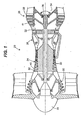
- Fig. 1 is a sectional view of a gas turbine engine constructed in accordance with the teachings of the disclosure;
- Fig. 2 is a plan view of a turbine blade constructed in accordance with the teachings of the disclosure;
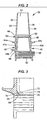
- Fig. 3 is an enlarged plan view of the turbine blade of Fig. 2;
- Fig. 4 is an enlarged plan view of the turbine blade of Fig. 2 with internal passages shown in phantom;
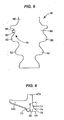
- Fig. 5 is a schematic representation of a serrated root fillet constructed in accordance with the teachings of the disclosure;
- Fig. 6 is a sectional view of a flared buttress constructed in accordance with the teachings of the disclosure;
- Fig. 7 is a plan view of a serrated fillet with stress concentrations represented; and
- Fig. 8 is a side view of the fillet of Fig. 7.
- While the following disclosure is susceptible to various modifications and alternative constructions, certain illustrative embodiments thereof have been shown in the drawings and will be described below in detail. It should be understood, however, that there is no intention to limit the disclosure to the specific forms disclosed, but on the contrary, the intention is to cover all modifications, alternative constructions, and equivalents falling within the scope of the disclosure as defined by the appended-claims.
- Referring now to the drawings, and with specific reference to Fig. 1, a gas turbine engine constructed in accordance with the teachings of the disclosure is generally referred to by
reference numeral 20. While the teachings of the disclosure can be used in conjunction with various types and designs of gas turbine engines, theengine 20 is depicted in a generic sense to depict one embodiment wherein the turbine blades of the present disclosure can be effectively employed. - As shown therein, the
engine 20 includes an outer housing orfan casing 22 within which reside acompressor section 24, acombustor section 26 downstream of thecompressor section 24, and aturbine section 28 downstream of thecombustor section 26. As one of ordinary skill in the art will be able to readily attest, thecompressor section 24 is able to greatly compress incoming air through a series ofstages 30 and introduce highly compressed air to thecombustor section 26. Within thecombustor section 26, fuel is introduced and combusted whereupon the extremely hot resulting combustion gases are directed through theturbine section 28 causingblades 32 therein to rotate at extremely high velocities. Air enters theengine 20 at anozzle 33 and exits theengine 20 at anoutlet 34 at extremely high velocities, thus providing the power or thrust desirable for the given application of theengine 20. - More specifically, the
engine 20 includes a central rotor orshaft assembly 36 extending and interconnecting thecompressor section 24 andturbine section 28. A plurality of theblades 32 extend from thecompressor section 24 and a plurality ofblades 39 extend from theturbine section 28, both in a radially outward fashion. Moreover, theblades vanes compressor section 24 and theturbine section 28, respectively. It is the orientation and proximity of theblades 32 andvanes 40 which cause the air to be compressed within thecompressor section 24 and the orientation and proximity of theblades 39 and vanes 40 that cause theturbine section 28 to generate the desired thrust. Moreover, as theblades shaft assembly 36, the process is perpetual and interconnected in that the hot combustion gases cause theturbine blades 39 to rotate, in turn causing thecompressor blades 32 to rotate thereby drawing in further air for compression and combustion. - Referring now to Figs. 2 and 4, one of the
turbine blades 39 is shown in further detail. Theblade 39 may include anairfoil 42 extending from aplatform 44, itself extending from aneck 46, itself extending from amounting root 48. As one of ordinary skill in the art will readily understand, themounting root 48 includes a plurality ofserrations 50 adapted to slidably interfit with openings (not shown) provided in theshaft assembly 36 of theengine 20 so as to secure theblades 39 thereto, and be able to withstand the extremely high centrifugal forces encountered when theblades 39 rotate at operating speed. - The
airfoil 42 can be provided in a variety of different shapes, orientations, concavities, and convexities, so as to optimize the operation of the engine. From Fig. 2, it will be noted that theairfoil 42 includes a leadingedge 52, aconcave interior 54, atrailing edge 56, and anouter skin 58. Theairfoil 42 of Figs. 2 and 4 is shown from the concave, or pressure side. - Referring now to the
platform 44, it is shown to be perpendicular to theairfoil 42 and also include a leadingedge 60 and atrailing edge 62. Extending from theplatform 44 in a direction opposite to theairfoil 42 is theneck 46. Theneck 46 includesbuttress rails edge 51 andtrailing edge 49, respectively. As will be described in further detail herein, the buttress rails 47a and 47b are provided to enhance the structural strength and rigidity of theblade 39. Buttress rails also provide blade to blade sealing capability. A plurality of protrusions 64, known as angel wings, extend outwardly from the buttress rails 47a and 47b with afirst wing 64a extending in the leading edge direction proximate theplatform 44, asecond wing 64b extending in the same direction, but proximate the mountingroot 48, and athird wing 64c extending in the trailing edge direction in alignment with thefirst wing 64a. The wings 64 form a continuous ring with other blades 39 (not shown), which combine with a matching ring (not shown) formed by the adjacentnon-rotating vanes 41 to form a loose seal to meter cooling air flowing radially outward along the leadingedge 51 and trailingedge 49. - Referring now to Figs. 3 and 6, a buttress rail with a flared
bottom 66 of theneck 46 is shown in more detail. As shown therein, wherein theneck 46 is substantially linear in construction and extends parallel to theair foil 42, it will noted that the flared buttress 66 is provided in a lower-most portion of theneck 46 proximate the mountingroot 48. The flared buttress 66 forms a substantially triangularly shaped reinforcement region for connection of theneck 46 to the mountingroot 48, to spread out the local stress concentration due to the stiff buttress rail, and to increase the serviceable life of theblade 39. In other embodiments, shapes other than triangular ones can be employed for the flared buttress including, but not limited to, rectangular shapes, linear strips, and angled supports. The flared buttress illustrated may be provided a pressure side of the airfoil. - With specific reference to Fig. 6, the flared buttress 66 is shown to include a
lower edge 68, aphantom side edge 70, and ahypotenuse 72. The hypotenuse 72 may be substantially arcuate in shape and include acurvilinear section 74 terminating in alower lip 76. While the flared buttress 66 can be manufactured of a variety of different dimensions, the applicants have found that a ratio of thelower edge 68 or lateral dimension to the phantom side edge orlongitudinal dimension 70 of seventy-five percent to be particularly advantageous. - With regard to the material from which the
blade 39 is made, it is to be understood that any of a variety of high temperature capability, strong materials be employed, with directionally solidified, cast nickel superalloy being one example. Also, theblade 39 includes a plurality ofcooling passages 77. By providing thecooling passages 77 through theblade 39, cooling air is able to enter theblade 39 at the bottom of theroot 48, travel through theneck 46, follow a serpentine path through theairfoil 42, and exit from cooling holes at theleading edge 51. In so doing, theblade 39 is kept at a sufficiently low temperature to ensure proper operation. - Another feature of the present disclosure which reduces the overall stress of the
blade 39, and thus improves its serviceable life, is the dimension or shape under which the filleted or serrated mountingroot 48 is constructed. Referring now to Fig. 5, the mountingroot 48 is shown to include a compound radiusedfillet 78 at anupper region 80 proximate the flaredbuttress 66. Similar to the flared buttress 66, the compound radiusedfillet 78 is provided proximate the leading edge of theblade 39. Apcordingly, the substantial forces encountered by the leading edge of theblade 39 when theengine 20 is in operation, can be better withstood owing to the reduced concentrated stress due to the combination of the flared buttress and compound fillet. - While a number of different dimensions can be used to form the compound radiused
fillet 78, Figs. 5, 7, and 8 depicts one particularly advantageous embodiment wherein afirst radius 82 relative to asecond radius 84 is approximately five to six, or in other words, 87.5 percent of the other. This is in opposition to conventional fillets which only provide for a uniformly radiused serrated mountingroot 48. Moreover, as shown in Figs. 7 and 8, a concentration ofstress 86 is found at the leading edge pressure side of theroot 48 under the buttressrail 47a and above thetop serration 88. By increasing the radius locally atlocation 86, the stress due to the curvature is reduced, thus increasing the life of theblade 39. Stress atlocations - From the foregoing, one of ordinary skill in the art will readily understand that the teachings of the disclosure can be used to construct a turbine blade having an improved and extendible serviceable life in that the blade is better able to withstand the substantial operating forces the blade is subjected to during operation of the engine. More specifically, by providing a flared buttress and compound radiused fillet at a leading edge of the blade, the ability of the blade to withstand those forces is improved, the tendency of the blade to fatigue or break proximate the joint between the air foil and mounting root is reduced, and thus the serviceable life of the engine is increased.
Claims (13)
- A turbine blade (39) comprising:a platform (44) having a first or flowpath side, second or under side, a leading edge (52), and a trailing edge (56);an airfoil (42) extending from the platform first or flow path side;a neck (46) extending from the platform second or under side;a blade root (48) extending from the neck (46); anda flared buttress (66) forming a part of the neck (46) and extending between the platform (44) second side and the blade root (48).
- A turbine blade of claim 1, wherein the flared buttress (66) is proximate the leading edge (52) of the platform (44).
- The turbine blade of claim 1 or 2, wherein the airfoil (42) includes a pressure side and a suction side, and wherein the flared buttress (66) is proximate the airfoil pressure side.
- The turbine blade of any preceding claim, wherein the flared buttress (66) is triangular in shape.
- The turbine blade of claim 4, wherein the flared buttress (66) includes a longitudinal dimension (70) and a lateral dimension (68), the longitudinal dimension (70) being greater than the lateral dimension (68).
- The turbine blade of claim 5, wherein the lateral dimension (68) is approximately seventy-five percent of the longitudinal dimension (70).
- The turbine blade of any preceding claim, wherein the blade root (48) includes a plurality of serrations (50).
- The turbine blade of claim 7, wherein at least one of the plurality of serrations (50) includes a compound fillet radius (78).
- The turbine blade of claim 8, wherein the serration (50) with the compound fillet radius (78) is proximate the leading edge (52) of the platform (44).
- The turbine blade of claim 8, wherein the radius comprising the compound radius fillet (78) has first and second radii (82,84) having a ratio of approximately five to six.
- A method of manufacturing a turbine blade (39), comprising:manufacturing a platform (44) having a flowpath side, an under side, a leading edge (52), and a trailing edge (56), with an airfoil (42) extending from the platform flowpath side, a neck (46) extending from the platform under side, and a blade root (48) extending from the neck (46); andforming a flared buttress (66) in the neck (46) between the platform under side and the blade root (48).
- The method of claim 11 further including the steps of providing the blade with the features of any of claims 2 to 10.
- A gas turbine engine (20), comprising:a compressor section (24);a combustor (26) downstream of the compressor section (24); anda turbine section (28) downstream of the combustor (26), the turbine having a central rotatable shaft (36) from which a plurality of turbine blades (39) extend, each turbine blade being a blade as claimed in any of claims 1 to 10.
Applications Claiming Priority (1)
| Application Number | Priority Date | Filing Date | Title |
|---|---|---|---|
| US10/911,298 US20060029500A1 (en) | 2004-08-04 | 2004-08-04 | Turbine blade flared buttress |
Publications (1)
| Publication Number | Publication Date |
|---|---|
| EP1624157A2 true EP1624157A2 (en) | 2006-02-08 |
Family
ID=34981348
Family Applications (1)
| Application Number | Title | Priority Date | Filing Date |
|---|---|---|---|
| EP05254676A Withdrawn EP1624157A2 (en) | 2004-08-04 | 2005-07-27 | Turbine blade flared buttress |
Country Status (5)
| Country | Link |
|---|---|
| US (1) | US20060029500A1 (en) |
| EP (1) | EP1624157A2 (en) |
| JP (1) | JP2006046343A (en) |
| KR (1) | KR20060048993A (en) |
| CN (1) | CN1734060A (en) |
Cited By (3)
| Publication number | Priority date | Publication date | Assignee | Title |
|---|---|---|---|---|
| FR3004484A1 (en) * | 2013-04-11 | 2014-10-17 | Snecma | TURBOMACHINE DAWN COOPERATING WITH AUBES RETENTION DISC |
| CN105716835A (en) * | 2014-12-03 | 2016-06-29 | 中国飞机强度研究所 | Chuck-type wing loading device |
| CN109578084A (en) * | 2017-09-28 | 2019-04-05 | 中国航发商用航空发动机有限责任公司 | Blade and the method for improving blade aerodynamic performance |
Families Citing this family (2)
| Publication number | Priority date | Publication date | Assignee | Title |
|---|---|---|---|---|
| US8448443B2 (en) * | 2007-10-11 | 2013-05-28 | General Electric Company | Combustion liner thimble insert and related method |
| US9249666B2 (en) | 2011-12-22 | 2016-02-02 | General Electric Company | Airfoils for wake desensitization and method for fabricating same |
Family Cites Families (27)
| Publication number | Priority date | Publication date | Assignee | Title |
|---|---|---|---|---|
| US4236870A (en) * | 1977-12-27 | 1980-12-02 | United Technologies Corporation | Turbine blade |
| US4180373A (en) * | 1977-12-28 | 1979-12-25 | United Technologies Corporation | Turbine blade |
| US4302062A (en) * | 1979-09-20 | 1981-11-24 | United Technologies Corporation | Turbine blade support |
| US4645425A (en) * | 1984-12-19 | 1987-02-24 | United Technologies Corporation | Turbine or compressor blade mounting |
| US4872812A (en) * | 1987-08-05 | 1989-10-10 | General Electric Company | Turbine blade plateform sealing and vibration damping apparatus |
| US4784573A (en) * | 1987-08-17 | 1988-11-15 | United Technologies Corporation | Turbine blade attachment |
| US4813848A (en) * | 1987-10-14 | 1989-03-21 | United Technologies Corporation | Turbine rotor disk and blade assembly |
| US5674050A (en) * | 1988-12-05 | 1997-10-07 | United Technologies Corp. | Turbine blade |
| US5135354A (en) * | 1990-09-14 | 1992-08-04 | United Technologies Corporation | Gas turbine blade and disk |
| US5147180A (en) * | 1991-03-21 | 1992-09-15 | Westinghouse Electric Corp. | Optimized blade root profile for steam turbine blades |
| US5302085A (en) * | 1992-02-03 | 1994-04-12 | General Electric Company | Turbine blade damper |
| US5313786A (en) * | 1992-11-24 | 1994-05-24 | United Technologies Corporation | Gas turbine blade damper |
| US5228835A (en) * | 1992-11-24 | 1993-07-20 | United Technologies Corporation | Gas turbine blade seal |
| US5435694A (en) * | 1993-11-19 | 1995-07-25 | General Electric Company | Stress relieving mount for an axial blade |
| US5501575A (en) * | 1995-03-01 | 1996-03-26 | United Technologies Corporation | Fan blade attachment for gas turbine engine |
| US5827047A (en) * | 1996-06-27 | 1998-10-27 | United Technologies Corporation | Turbine blade damper and seal |
| US5820774A (en) * | 1996-10-28 | 1998-10-13 | United Technologies Corporation | Ceramic core for casting a turbine blade |
| US5924699A (en) * | 1996-12-24 | 1999-07-20 | United Technologies Corporation | Turbine blade platform seal |
| US5785499A (en) * | 1996-12-24 | 1998-07-28 | United Technologies Corporation | Turbine blade damper and seal |
| US6206642B1 (en) * | 1998-12-17 | 2001-03-27 | United Technologies Corporation | Compressor blade for a gas turbine engine |
| US6315298B1 (en) * | 1999-11-22 | 2001-11-13 | United Technologies Corporation | Turbine disk and blade assembly seal |
| US6390775B1 (en) * | 2000-12-27 | 2002-05-21 | General Electric Company | Gas turbine blade with platform undercut |
| US6490791B1 (en) * | 2001-06-22 | 2002-12-10 | United Technologies Corporation | Method for repairing cracks in a turbine blade root trailing edge |
| US6851932B2 (en) * | 2003-05-13 | 2005-02-08 | General Electric Company | Vibration damper assembly for the buckets of a turbine |
| JP4254352B2 (en) * | 2003-06-04 | 2009-04-15 | 株式会社Ihi | Turbine blade |
| US6808368B1 (en) * | 2003-06-13 | 2004-10-26 | General Electric Company | Airfoil shape for a turbine bucket |
| US7097429B2 (en) * | 2004-07-13 | 2006-08-29 | General Electric Company | Skirted turbine blade |
-
2004
- 2004-08-04 US US10/911,298 patent/US20060029500A1/en not_active Abandoned
-
2005
- 2005-07-27 EP EP05254676A patent/EP1624157A2/en not_active Withdrawn
- 2005-08-01 KR KR1020050070102A patent/KR20060048993A/en not_active Abandoned
- 2005-08-01 JP JP2005222391A patent/JP2006046343A/en active Pending
- 2005-08-03 CN CNA2005100911335A patent/CN1734060A/en active Pending
Cited By (6)
| Publication number | Priority date | Publication date | Assignee | Title |
|---|---|---|---|---|
| FR3004484A1 (en) * | 2013-04-11 | 2014-10-17 | Snecma | TURBOMACHINE DAWN COOPERATING WITH AUBES RETENTION DISC |
| US9567861B2 (en) | 2013-04-11 | 2017-02-14 | Snecma | Turbomachine vane cooperating with a vane retention disk |
| CN105716835A (en) * | 2014-12-03 | 2016-06-29 | 中国飞机强度研究所 | Chuck-type wing loading device |
| CN105716835B (en) * | 2014-12-03 | 2018-04-10 | 中国飞机强度研究所 | A kind of chuck type wing loading device |
| CN109578084A (en) * | 2017-09-28 | 2019-04-05 | 中国航发商用航空发动机有限责任公司 | Blade and the method for improving blade aerodynamic performance |
| CN109578084B (en) * | 2017-09-28 | 2021-08-03 | 中国航发商用航空发动机有限责任公司 | Blade and method for improving aerodynamic performance of blade |
Also Published As
| Publication number | Publication date |
|---|---|
| US20060029500A1 (en) | 2006-02-09 |
| KR20060048993A (en) | 2006-05-18 |
| CN1734060A (en) | 2006-02-15 |
| JP2006046343A (en) | 2006-02-16 |
Similar Documents
| Publication | Publication Date | Title |
|---|---|---|
| CA2548168C (en) | Turbine airfoil with variable and compound fillet | |
| US8961134B2 (en) | Turbine blade or vane with separate endwall | |
| US8147207B2 (en) | Compressor blade having a ratio of leading edge sweep to leading edge dihedral in a range of 1:1 to 3:1 along the radially outer portion | |
| US10822957B2 (en) | Fillet optimization for turbine airfoil | |
| EP0716217B1 (en) | Trailing edge ejection slots for film cooled turbine blade | |
| US7452186B2 (en) | Turbine blade including revised trailing edge cooling | |
| EP1512835B1 (en) | Rotor blade and gas turbine engine comprising a corresponding rotor assembly | |
| EP1314855A2 (en) | Gas turbine engine aerofoil | |
| EP1326005B1 (en) | Turbine blade with a continuous step-down platform and corresponding turbine | |
| EP3032033B2 (en) | A vane assembly of a gas turbine engine | |
| EP2374997B1 (en) | Component for a gas turbine engine | |
| EP2617944B1 (en) | Turbomachine blade tip shroud | |
| US10830082B2 (en) | Systems including rotor blade tips and circumferentially grooved shrouds | |
| JPH04228805A (en) | Turbine blade outer end attaching structure | |
| GB2155558A (en) | Turbomachinery rotor blades | |
| US20150110616A1 (en) | Gas turbine nozzle trailing edge fillet | |
| US7874794B2 (en) | Blade row for a rotary machine and method of fabricating same | |
| US8435006B2 (en) | Fan | |
| US20060029500A1 (en) | Turbine blade flared buttress | |
| EP4136324B1 (en) | Turbine blade | |
| CA2776536C (en) | Blade for a gas turbine engine | |
| US12270317B2 (en) | Airfoils for gas turbine engines | |
| EP3889392B1 (en) | Turbomachine rotor blade with a cooling circuit having an offset rib | |
| EP3828386B1 (en) | Turbomachine rotor blade having a variable elliptical trailing edge |
Legal Events
| Date | Code | Title | Description |
|---|---|---|---|
| PUAI | Public reference made under article 153(3) epc to a published international application that has entered the european phase |
Free format text: ORIGINAL CODE: 0009012 |
|
| AK | Designated contracting states |
Kind code of ref document: A2 Designated state(s): AT BE BG CH CY CZ DE DK EE ES FI FR GB GR HU IE IS IT LI LT LU LV MC NL PL PT RO SE SI SK TR |
|
| AX | Request for extension of the european patent |
Extension state: AL BA HR MK YU |
|
| STAA | Information on the status of an ep patent application or granted ep patent |
Free format text: STATUS: THE APPLICATION HAS BEEN WITHDRAWN |
|
| 18W | Application withdrawn |
Effective date: 20080407 |