EP1624142B1 - Vehicle comprising vehicular electrical disengaging door latch apparatus - Google Patents
Vehicle comprising vehicular electrical disengaging door latch apparatus Download PDFInfo
- Publication number
- EP1624142B1 EP1624142B1 EP20050016814 EP05016814A EP1624142B1 EP 1624142 B1 EP1624142 B1 EP 1624142B1 EP 20050016814 EP20050016814 EP 20050016814 EP 05016814 A EP05016814 A EP 05016814A EP 1624142 B1 EP1624142 B1 EP 1624142B1
- Authority
- EP
- European Patent Office
- Prior art keywords
- module
- door
- vehicle
- occupant
- seat
- Prior art date
- Legal status (The legal status is an assumption and is not a legal conclusion. Google has not performed a legal analysis and makes no representation as to the accuracy of the status listed.)
- Expired - Lifetime
Links
Images

Classifications
-
- E—FIXED CONSTRUCTIONS
- E05—LOCKS; KEYS; WINDOW OR DOOR FITTINGS; SAFES
- E05B—LOCKS; ACCESSORIES THEREFOR; HANDCUFFS
- E05B81/00—Power-actuated vehicle locks
- E05B81/12—Power-actuated vehicle locks characterised by the function or purpose of the powered actuators
- E05B81/14—Power-actuated vehicle locks characterised by the function or purpose of the powered actuators operating on bolt detents, e.g. for unlatching the bolt
-
- B—PERFORMING OPERATIONS; TRANSPORTING
- B60—VEHICLES IN GENERAL
- B60N—SEATS SPECIALLY ADAPTED FOR VEHICLES; VEHICLE PASSENGER ACCOMMODATION NOT OTHERWISE PROVIDED FOR
- B60N2/00—Seats specially adapted for vehicles; Arrangement or mounting of seats in vehicles
- B60N2/02—Seats specially adapted for vehicles; Arrangement or mounting of seats in vehicles the seat or part thereof being movable, e.g. adjustable
- B60N2/04—Seats specially adapted for vehicles; Arrangement or mounting of seats in vehicles the seat or part thereof being movable, e.g. adjustable the whole seat being movable
- B60N2/12—Seats specially adapted for vehicles; Arrangement or mounting of seats in vehicles the seat or part thereof being movable, e.g. adjustable the whole seat being movable slidable and tiltable
-
- E—FIXED CONSTRUCTIONS
- E05—LOCKS; KEYS; WINDOW OR DOOR FITTINGS; SAFES
- E05B—LOCKS; ACCESSORIES THEREFOR; HANDCUFFS
- E05B77/00—Vehicle locks characterised by special functions or purposes
- E05B77/22—Functions related to actuation of locks from the passenger compartment of the vehicle
- E05B77/24—Functions related to actuation of locks from the passenger compartment of the vehicle preventing use of an inner door handle, sill button, lock knob or the like
- E05B77/28—Functions related to actuation of locks from the passenger compartment of the vehicle preventing use of an inner door handle, sill button, lock knob or the like for anti-theft purposes, e.g. double-locking or super-locking
-
- E—FIXED CONSTRUCTIONS
- E05—LOCKS; KEYS; WINDOW OR DOOR FITTINGS; SAFES
- E05B—LOCKS; ACCESSORIES THEREFOR; HANDCUFFS
- E05B13/00—Devices preventing the key or the handle or both from being used
- E05B13/001—Covers preventing access to handles or keys
-
- E—FIXED CONSTRUCTIONS
- E05—LOCKS; KEYS; WINDOW OR DOOR FITTINGS; SAFES
- E05B—LOCKS; ACCESSORIES THEREFOR; HANDCUFFS
- E05B47/00—Operating or controlling locks or other fastening devices by electric or magnetic means
- E05B2047/0048—Circuits, feeding, monitoring
- E05B2047/0071—Connecting lockparts by electronic communication means only, e.g. bus systems, time multiplexing
-
- E—FIXED CONSTRUCTIONS
- E05—LOCKS; KEYS; WINDOW OR DOOR FITTINGS; SAFES
- E05B—LOCKS; ACCESSORIES THEREFOR; HANDCUFFS
- E05B63/00—Locks or fastenings with special structural characteristics
- E05B63/0052—Locks mounted on the "frame" cooperating with means on the "wing"
-
- E—FIXED CONSTRUCTIONS
- E05—LOCKS; KEYS; WINDOW OR DOOR FITTINGS; SAFES
- E05B—LOCKS; ACCESSORIES THEREFOR; HANDCUFFS
- E05B81/00—Power-actuated vehicle locks
- E05B81/54—Electrical circuits
- E05B81/90—Manual override in case of power failure
-
- Y—GENERAL TAGGING OF NEW TECHNOLOGICAL DEVELOPMENTS; GENERAL TAGGING OF CROSS-SECTIONAL TECHNOLOGIES SPANNING OVER SEVERAL SECTIONS OF THE IPC; TECHNICAL SUBJECTS COVERED BY FORMER USPC CROSS-REFERENCE ART COLLECTIONS [XRACs] AND DIGESTS
- Y10—TECHNICAL SUBJECTS COVERED BY FORMER USPC
- Y10T—TECHNICAL SUBJECTS COVERED BY FORMER US CLASSIFICATION
- Y10T292/00—Closure fasteners
- Y10T292/08—Bolts
- Y10T292/1043—Swinging
- Y10T292/1044—Multiple head
- Y10T292/1045—Operating means
- Y10T292/1047—Closure
Definitions
- the present invention relates to a vehicle comprising a vehicular electrical disengaging door latch apparatus according to the preamble part of independent claim 1.
- a mechanical lock canceling mechanism which can mechanically disengage a latch of the electrical disengaging latch apparatus even if an electric actuator for opening fails to be operated due to a deterioration of a battery or the like with respect to the electric actuator for opening (for example , Japanese Utility Model Application Laid-Open No. 63-146066 ).
- EP 0710755 A1 discloses an electrically operated vehicle door lock which is readable on the preamble part of independent claim 1.
- Said door lock is fitted to a door post, and a striker is fitted to a door itself.
- An electric motor is controlled by a central electric unit which is operated In response to input signals received from switches on inside and outside door handles and front-door locks or a remote control unit.
- a manual emergency release lever is located inside the passenger compartment on the door post and is connected via the interposition of a tie to a first arm of the door lock.
- the objective of the present invention is to provide a vehicle comprising a vehicular electrical disengaging door latch apparatus including antitheft means, which securely prevents the door-open operating module from being operated from the outside.
- a vehicle comprising a vehicular electrical disengaging door latch apparatus having the combination of features of independent claim 1.
- a distance from the waist line of the door to the door-open operating module is equal to or more than a length of a hand of a normal human being while maintaining an easiness of a door open operation by the occupant on the vehice. Accordingly, it is impossible to operate the door-open operating module by forming a small space capable of inserting a hand, a tool or the like into the passenger room from the outside of the passenger room, and an excellent antitheft property is obtained.
- the vehicle state detecting section controls the driving module so as to move to the position covering the door-open operating module and be allowed to be stopped by the stopper module at the position, when the occupant gets out of the vehicle and the vehicle state detecting section detects the exit state of the occupant, it is possible to securely prevent the door-open operating module from being operated.
- the door-open operating module can be securely covered by the seat cushion, and it is possible to securely prevent the door-open operating module from being operated from the outside of the passenger room.
- the vehicle state detecting section is set so as to activate the driving module when the vehicle state detecting section detects the fact that the door latch module is operated from the unlocked state to the locked state from the outside of the passenger room, it is possible to securely detect the fact that the occupant gets out of the vehicle, there is no risk of a malfunction, and a commodity property is improved.
- the vehicle state detecting section is set so as to activate the driving module when the vehicle state detecting section detects the fact that the occupant is away from the passenger room, it is possible to securely detect the fact that the passenger gets out of the vehicle, there is no risk of a malfunction, and a commodity property is improved.
- the vehicle state detecting section is set so as to activate the driving module when the vehicle state detecting section detects the fact that no load is applied to the pressure detection type sitting sensor provided in the seat cushion, it is possible to securely detect the fact that the passenger gets out of the vehicle, there is no risk of a malfunction, and a commodity property is improved.
- the door-open operating module is covered with the cover provided in the seat cushion, the door-open operating module is completely invisible from the outside of the passenger room, an opportunity for generating a wicked attempt is lost, and an antitheft property is significantly improved.
- the object, of providing the vehicular electrical disengaging door latch apparatus which can not operate a door-open operating means of a mechanical lock canceling mechanism by forming a small space capable of inserting a hand or a tool or the like into a passenger room (an occupant room) from the outside of the passenger room, is achieved by a vehicular electrical disengaging door latch apparatus according to claim 1.
- the vehicular electrical disengaging door latch apparatus includes at least: a striker provided in the vehicle main body or the door, the door latch module provided in the door or the vehicle main body so as to freely engage with and disengage from the striker, the latch disengaging means capable of electrically disengaging the door latch means, the control means capable of controlling the latch disengaging module and a door-open operating module capable of mechanically disengaging the door latch module by other transmitting module than the latch disengaging module.
- the door-open operating means is arranged in the lower side of the seat cushion of the occupant scat or in the floor member opposing to the occupant seat
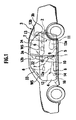
- Reference numerals 1 and 2 denote door larch means as door latch modules respectively provided in a center pillar 3a and a rear side panel 3b of a vehicle main body 3 so as to be freely engaged with and disengaged from strikers (not shown) placed in a front door 4 and a rear door 5.
- Reference numeral 6 denotes a latch disengaging means as a latch disengaging module which is coupled to the door latch means 1 and 2 via a wire harness 7 and can fully open by electrically disengaging the door latch means 1 and 2.
- a control module (not shown) which can control the latch disengaging means 6 and an operation switch (not shown) which can be operated from the inside of a passenger room (an occupant room) are interposed in the latch disengaging means 6.
- Reference numerals 8 and 9 denote door-open operating means as door-open operating modules which can respectively disengage the door latch means 1 and 2 mechanically by other transmitting means 10 and 11 constituted by a cable than the latch disengaging means 6.
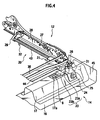
- the door-open operating means 8 and 9 are arranged within a box 15 arranged in a floor member 14 which exists in lower sides of seat cushions 12a and 13a of a front seat 12 and a rear seat 13 as respectively an occupant seat and opposing to the front seat 12 and the rear seat 13 (in this case, the rear box is not illustrated), and are formed in a lever shape as shown in Figs. 4 and 5 which an occupant (not shown) can operate.
- a description will be given in detail of the floor member 14 in which the box 15 is arranged.
- the floor member 14 is constituted by a floor panel 16 itself in which the door-open operating means 8 is arranged, and a cross member 17 which is supported to the floor panel 16 and in which the door-open operating means 8 is arranged. As shown in Figs. 4 and 5 , the door-open operating means 8 is arranged in a hole 17a provided in a top portion of the cross member 17.
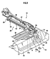
- the front seat 12 is constituted at least by a seat cushion 12a, a slide apparatus (a power slide apparatus) 20 which can move the seat cushion 12a forward and backward and can fix the seat cushion 12a at an appropriate position, a seat back 12b, and a covering means 23 which is suspended from the slide apparatus 20 of the seat cushion 12a.
- the covering means 23 includes a bracket portion 23a which is perpendicularly suspended, and a cover portion 23b as a cover which covers the door-open operating means 8.
- the slide apparatus 20 is provided with a drive means (driving means) 21 as a driving module which can move the seat cushion 12a forward and backward, a stopper means (not shown) as a stopper module which can fix the seat cushion 12a at appropriate front and rear positions, and a keyless entry system 22 as a vehicle state detecting section which detects an exit state of an occupant.
- driving means driving means
- stopper means not shown
- keyless entry system 22 as a vehicle state detecting section which detects an exit state of an occupant.
- the slide apparatus moves to a position covering the door-open operating means 8 by controlling the drive means 21 and can be stopped by the stopper means at the position.
- the drive means 21 is constituted by a front bracket 25 which is fixed to the cross member 17 by a bolt 24, a rear bracket 32 which is supported to the floor panel 16, a fixed rail 26 which is built between the front bracket 25 and the rear bracket 32, a movable rail 28 which is supported to a side frame 27 ( FIG. 3 ) of the seat cushion 12a and is supported to the fixed rail 26 so as to freely move forward and backward, a lead screw 43 which is supported to a transmission case 31 fixed to a bracket 29 ( FIG.
- a motor (not shown) which drives the lead screw 43, and a transmission shaft 44 forming a vehicle width direction extended from the motor, and is structured so as to transmit a rotation power to the lead screw 43 forming a longitudinal direction by the transmission case 31.
- a function of the stopper means is provided.
- the rear seat 13 is constituted at least by the seat cushion 13a and a seat back 13b.
- the door-open operating means 8 and 9 are arranged within the box 15 provided in the cross member 17 in the lower side of the seat cushion 12a of the front seat 12 and within the box (not shown) provided in the floor panel 16 positioned just below the seat cushion 13a of the rear seat 13.
- the distance from the waist line WS is further elongated by arranging the door-open operating means 8 and 9 close to a center of the passenger room, for example, in a floor tunnel 45 side as shown in Figs. 4 and 5 , a more excellent antitheft property is obtained.
- the door-open operating means 8 is moved to a covered position by controlling the drive means 21 and can be stopped by the stopper means at the position. Accordingly, it is possible to securely prevent the door-open operating means 8 from being operated.
- the structure is made such that the drive means 21 is activated when the keyless entry system 22 detects a fact that the door latch means 1 is operated from the unlocked state to the locked state from the outside of the passenger room, it is possible to securely detect the fact that the occupant gets out of the vehicle, there is no risk that a malfunction is generated, and a commodity property is improved.
- the door-open operating means 8 is covered with a covering means 23 provided in the seat cushion 12a of the front seat 12, the door-open operating means 8 is absolutely invisible from the outside of the passenger room, an opportunity for generating a wicked attempt is lost, and an antitheft property is significantly improved.
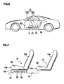
- Reference numeral 40 denotes a exit switch, which is provided in a lower side of the front seat 12 (for example, the seat back 12b).
- the front seat 12 is structured such that the seat cushion 12a can move to a frontmost position covering the door-open operating means 8 by a walk-in means (not shown) as a walk-in module which always urges die seat cushion 118 to a front side.
- the seat back 12b flops into a from side as shown by a two-dot chain line.
- a slide apparatus 41 in which the walk-in means is arranged is movable forward and backward and can be fixed at an appropriate position.
- the exit switch 40 is reset to an operable state by opening a door 42 so as to reset the front seat 12 to an original position, and the door-open operating means 8 becomes in an operable state.
- the door-open operating means 8 is securely covered with the seat cushion 12a, and it is possible to securely prevent the door-open operating means 8 from the outside of the passenger room on the basis of the simple structure without necessity of a complex system such as a power slide apparatus or the like.
- Reference numeral 50 denotes a pressure detection type sitting sensor as another "vehicle state detection section".
- the pressure detection type sitting sensor 50 is provided in the seat cushions 12a and 13a, and is set so as to determine that the occupant is absent from the passenger room at a time of detecting a state in which no load is applied to the seat cushions 12a and 13a, thereby activating the drive means 21.
- the structure is made so as to activate the drive means 21 at a time of detecting the state in which no load is applied to the seat cushions 12a and 13a when the occupant gets out of the vehicle that is the fact that the occupant is absent from the passenger room, it is possible to securely detect the fact that the occupant gets out of the vehicle, there is no risk that the malfunction is generated, and the commodity property is improved.
- both of the front door 4 and the rear door 5 can rotate around the well-known hinge (not shown) in the front side so as to open and close the door, however, the technical teaching also can be applied to a slide door.
- the means for detecting the exit state of the occupant by the vehicle state detection section it is possible to utilize a pyroelectric type infrared ray sensor detecting an infrared ray energy or an ultrasonic sensor can be utilized without being limited to the sitting sensor.
Landscapes
- Engineering & Computer Science (AREA)
- Aviation & Aerospace Engineering (AREA)
- Transportation (AREA)
- Mechanical Engineering (AREA)
- Lock And Its Accessories (AREA)
Description
- The present invention relates to a vehicle comprising a vehicular electrical disengaging door latch apparatus according to the preamble part of independent claim 1.
- As a vehicular electrical disengaging door latch apparatus for opening a door of a vehicle, there is a mechanical lock canceling mechanism which can mechanically disengage a latch of the electrical disengaging latch apparatus even if an electric actuator for opening fails to be operated due to a deterioration of a battery or the like with respect to the electric actuator for opening (for example ,
Japanese Utility Model Application Laid-Open No. 63-146066 - However, in the prior art mentioned above ,since a door-open operating means of the mechanical lock canceling mechanism is attached near a wait line of the door, there is a risk that the door-open operating means can be easily operated only by forming a small space capable of inserting a hand, a tool or the like into a passenger room from an exterior side of the passenger room by breaking a window or the like. Accordingly, an improvement is required. The present invention has been achieved with such points in mind.
-
EP 0710755 A1 discloses an electrically operated vehicle door lock which is readable on the preamble part of independent claim 1. Said door lock is fitted to a door post, and a striker is fitted to a door itself. An electric motor is controlled by a central electric unit which is operated In response to input signals received from switches on inside and outside door handles and front-door locks or a remote control unit. A manual emergency release lever is located inside the passenger compartment on the door post and is connected via the interposition of a tie to a first arm of the door lock. - The objective of the present invention is to provide a vehicle comprising a vehicular electrical disengaging door latch apparatus including antitheft means, which securely prevents the door-open operating module from being operated from the outside.
- According to the present invention, said objective is solved by a vehicle comprising a vehicular electrical disengaging door latch apparatus having the combination of features of independent claim 1.
- Accordingly, since the door-opening module is arranged in the lower side of the seat cushion of the occupant seat or in the floor member opposing to the occupant seat, a distance from the waist line of the door to the door-open operating module is equal to or more than a length of a hand of a normal human being while maintaining an easiness of a door open operation by the occupant on the vehice. Accordingly, it is impossible to operate the door-open operating module by forming a small space capable of inserting a hand, a tool or the like into the passenger room from the outside of the passenger room, and an excellent antitheft property is obtained.
- Since the vehicle state detecting section controls the driving module so as to move to the position covering the door-open operating module and be allowed to be stopped by the stopper module at the position, when the occupant gets out of the vehicle and the vehicle state detecting section detects the exit state of the occupant, it is possible to securely prevent the door-open operating module from being operated.
- Preferred embodiments of the present invention are laid down in the subclaims.
- Preferably, since the seat cushion is urged to the front side so as to move to the frontmost position of the slide apparatus by activating the occupant seat in a walk-in manner when the occupant gets out of the vehicle of the vehicle, the door-open operating module can be securely covered by the seat cushion, and it is possible to securely prevent the door-open operating module from being operated from the outside of the passenger room.
- Preferably, since the vehicle state detecting section is set so as to activate the driving module when the vehicle state detecting section detects the fact that the door latch module is operated from the unlocked state to the locked state from the outside of the passenger room, it is possible to securely detect the fact that the occupant gets out of the vehicle, there is no risk of a malfunction, and a commodity property is improved.
- Further preferably, since the vehicle state detecting section is set so as to activate the driving module when the vehicle state detecting section detects the fact that the occupant is away from the passenger room, it is possible to securely detect the fact that the passenger gets out of the vehicle, there is no risk of a malfunction, and a commodity property is improved.
- Still further preferably, since the vehicle state detecting section is set so as to activate the driving module when the vehicle state detecting section detects the fact that no load is applied to the pressure detection type sitting sensor provided in the seat cushion, it is possible to securely detect the fact that the passenger gets out of the vehicle, there is no risk of a malfunction, and a commodity property is improved.
- Preferably, since the door-open operating module is covered with the cover provided in the seat cushion, the door-open operating module is completely invisible from the outside of the passenger room, an opportunity for generating a wicked attempt is lost, and an antitheft property is significantly improved.
- In the following, the present invention is explained in greater detail by means of embodiments thereof in conjunction with the accompanying drawings, wherein:
-
Fig. 1 is a side elevational view showing a motor vehicle provided with a door latch means in accordance with a first embodiment; -
Fig. 2 is a side elevational view showing a box provided with a front seat and a door-open operating means inFig. 1 ; -
Fig. 3 is a front elevational view showing the box provided with the front seat and the door-open operating means inFig. 2 ; -
Fig. 4 is a perspective view showing the box provided with the front seat and the door-open operating means inFigs. 2 and 3 ; -
Fig. 5 is a perspective view showing a state in which the door-open operating means inFig. 4 is covered with a covering means; -
Fig. 6 is a side elevational view showing a motor vehicle provided with a door latch means in accordance with a second embodiment; and -
Fig. 7 is a side elevational view showing a seat provided with a vehicle state detecting portion in accordance with a third embodiment. - Below the preferred embodiments will be described in detail with reference to the accompanying drawings. Like members are designated by like reference characters.
- The object, of providing the vehicular electrical disengaging door latch apparatus which can not operate a door-open operating means of a mechanical lock canceling mechanism by forming a small space capable of inserting a hand or a tool or the like into a passenger room (an occupant room) from the outside of the passenger room, is achieved by a vehicular electrical disengaging door latch apparatus according to claim 1. Namely, the vehicular electrical disengaging door latch apparatus includes at least: a striker provided in the vehicle main body or the door, the door latch module provided in the door or the vehicle main body so as to freely engage with and disengage from the striker, the latch disengaging means capable of electrically disengaging the door latch means, the control means capable of controlling the latch disengaging module and a door-open operating module capable of mechanically disengaging the door latch module by other transmitting module than the latch disengaging module. Especially, the door-open operating means is arranged in the lower side of the seat cushion of the occupant scat or in the floor member opposing to the occupant seat
- A description will be given of a first embodiment with reference to
Figs. 1 to 5 . - Reference numerals 1 and 2 denote door larch means as door latch modules respectively provided in a
center pillar 3a and arear side panel 3b of a vehicle main body 3 so as to be freely engaged with and disengaged from strikers (not shown) placed in a front door 4 and arear door 5. - Reference numeral 6 denotes a latch disengaging means as a latch disengaging module which is coupled to the door latch means 1 and 2 via a
wire harness 7 and can fully open by electrically disengaging the door latch means 1 and 2. A control module (not shown) which can control the latch disengaging means 6 and an operation switch (not shown) which can be operated from the inside of a passenger room (an occupant room) are interposed in the latch disengaging means 6. -
Reference numerals 8 and 9 denote door-open operating means as door-open operating modules which can respectively disengage the door latch means 1 and 2 mechanically by other transmittingmeans 10 and 11 constituted by a cable than the latch disengaging means 6. The door-open operating means 8 and 9 are arranged within abox 15 arranged in afloor member 14 which exists in lower sides ofseat cushions front seat 12 and arear seat 13 as respectively an occupant seat and opposing to thefront seat 12 and the rear seat 13 (in this case, the rear box is not illustrated), and are formed in a lever shape as shown inFigs. 4 and5 which an occupant (not shown) can operate. A description will be given in detail of thefloor member 14 in which thebox 15 is arranged. Thefloor member 14 is constituted by afloor panel 16 itself in which the door-open operating means 8 is arranged, and across member 17 which is supported to thefloor panel 16 and in which the door-open operating means 8 is arranged. As shown inFigs. 4 and5 , the door-open operating means 8 is arranged in ahole 17a provided in a top portion of thecross member 17. - The
front seat 12 is constituted at least by aseat cushion 12a, a slide apparatus (a power slide apparatus) 20 which can move theseat cushion 12a forward and backward and can fix theseat cushion 12a at an appropriate position, aseat back 12b, and acovering means 23 which is suspended from theslide apparatus 20 of theseat cushion 12a. The covering means 23 includes abracket portion 23a which is perpendicularly suspended, and acover portion 23b as a cover which covers the door-open operating means 8. - The
slide apparatus 20 is provided with a drive means (driving means) 21 as a driving module which can move theseat cushion 12a forward and backward, a stopper means (not shown) as a stopper module which can fix theseat cushion 12a at appropriate front and rear positions, and akeyless entry system 22 as a vehicle state detecting section which detects an exit state of an occupant. When thekeyless entry system 22 detects the exit state of the occupant, in other words, when detecting a fact that the door latch means 1 and 2 are changed from an unlocked state to a locked state by operating from the outside of the passenger room by a portable device (not shown), the slide apparatus moves to a position covering the door-open operating means 8 by controlling the drive means 21 and can be stopped by the stopper means at the position. - The
drive means 21 is constituted by afront bracket 25 which is fixed to thecross member 17 by abolt 24, arear bracket 32 which is supported to thefloor panel 16, a fixedrail 26 which is built between thefront bracket 25 and therear bracket 32, amovable rail 28 which is supported to a side frame 27 (FIG. 3 ) of theseat cushion 12a and is supported to thefixed rail 26 so as to freely move forward and backward, alead screw 43 which is supported to atransmission case 31 fixed to a bracket 29 (FIG. 4 ) protruding from themovable rail 28 and amain frame 30 of theseat cushion 12a, a motor (not shown) which drives thelead screw 43, and atransmission shaft 44 forming a vehicle width direction extended from the motor, and is structured so as to transmit a rotation power to thelead screw 43 forming a longitudinal direction by thetransmission case 31. When stopping the motor, a function of the stopper means is provided. - The
rear seat 13 is constituted at least by theseat cushion 13a and a seat back 13b. - Since the structure is made as mentioned above, the door-open operating means 8 and 9 are arranged within the
box 15 provided in thecross member 17 in the lower side of theseat cushion 12a of thefront seat 12 and within the box (not shown) provided in thefloor panel 16 positioned just below theseat cushion 13a of therear seat 13. Accordingly, since distances from respective waist lines WS of the front door 4 and therear door 5, that is, lower edges ofwindows open operating means 8 and 9 by such a small space that a hand, a tool or the like can be inserted into the passenger room, that is, by a hole formed by breaking thewindows - Further, since the distance from the waist line WS is further elongated by arranging the door-open operating means 8 and 9 close to a center of the passenger room, for example, in a
floor tunnel 45 side as shown inFigs. 4 and5 , a more excellent antitheft property is obtained. - Further, when the occupant gets out of the vehicle of the vehicle and operates the
keyless entry system 22, whereby the exit state of the occupant is detected, the door-open operating means 8 is moved to a covered position by controlling the drive means 21 and can be stopped by the stopper means at the position. Accordingly, it is possible to securely prevent the door-open operating means 8 from being operated. - In other words, since the structure is made such that the drive means 21 is activated when the
keyless entry system 22 detects a fact that the door latch means 1 is operated from the unlocked state to the locked state from the outside of the passenger room, it is possible to securely detect the fact that the occupant gets out of the vehicle, there is no risk that a malfunction is generated, and a commodity property is improved. - Further, since the door-
open operating means 8 is covered with acovering means 23 provided in theseat cushion 12a of thefront seat 12, the door-open operating means 8 is absolutely invisible from the outside of the passenger room, an opportunity for generating a wicked attempt is lost, and an antitheft property is significantly improved. - A description will be given of a second embodiment with reference to
Fig. 6 . The same reference numerals and names are used in the same constituting members as those in the fust embodiment, and an overlapping description will be omitted. -
Reference numeral 40 denotes a exit switch, which is provided in a lower side of the front seat 12 (for example, theseat back 12b). When theexit switch 40 is operated, thefront seat 12 is structured such that theseat cushion 12a can move to a frontmost position covering the door-open operating means 8 by a walk-in means (not shown) as a walk-in module which always urges die seat cushion 118 to a front side. At this time, the seat back 12b flops into a from side as shown by a two-dot chain line. Aslide apparatus 41 in which the walk-in means is arranged is movable forward and backward and can be fixed at an appropriate position. When the occupant gets in (gets on) the vehicle again, theexit switch 40 is reset to an operable state by opening adoor 42 so as to reset thefront seat 12 to an original position, and the door-open operating means 8 becomes in an operable state. - In accordance with the structure mentioned above, since the
seat cushion 12a is urged to the front side so as to move to the frontmost position of theslide apparatus 41 by operating theexit switch 40 and activating thefront seat 12 in a walk-in manner when the occupant gets out of the vehicle, the door-open operating means 8 is securely covered with theseat cushion 12a, and it is possible to securely prevent the door-open operating means 8 from the outside of the passenger room on the basis of the simple structure without necessity of a complex system such as a power slide apparatus or the like. - A description will be given of a third embodiment with reference to
Fig. 7 . The same reference numerals and names are used in the same constituting members as those of the first embodiment, and an overlapping description will be omitted. -
Reference numeral 50 denotes a pressure detection type sitting sensor as another "vehicle state detection section". The pressure detectiontype sitting sensor 50 is provided in the seat cushions 12a and 13a, and is set so as to determine that the occupant is absent from the passenger room at a time of detecting a state in which no load is applied to the seat cushions 12a and 13a, thereby activating the drive means 21. - In accordance with the structure mentioned above, since the structure is made so as to activate the drive means 21 at a time of detecting the state in which no load is applied to the seat cushions 12a and 13a when the occupant gets out of the vehicle that is the fact that the occupant is absent from the passenger room, it is possible to securely detect the fact that the occupant gets out of the vehicle, there is no risk that the malfunction is generated, and the commodity property is improved.
- In the embodiments mentioned above, both of the front door 4 and the
rear door 5 can rotate around the well-known hinge (not shown) in the front side so as to open and close the door, however, the technical teaching also can be applied to a slide door. Further, as the means for detecting the exit state of the occupant by the vehicle state detection section, it is possible to utilize a pyroelectric type infrared ray sensor detecting an infrared ray energy or an ultrasonic sensor can be utilized without being limited to the sitting sensor.
Claims (6)
- Vehicle comprising a vehicular electrical disengaging door latch apparatus, the vehicular electrical disengaging door latch apparatus, comprising:a striker provided in one of a vehicle main body (3) and a door (4, 5) of the vehicle;a door latch module (1, 2) provided in one of the door (4, 5) and the vehicle main body (3) so as to freely engage with and disengage from the striker;a latch disengaging module (6) capable of electrically disengaging the door latch module (1, 2);a control module capable of controlling the latch disengaging module (6); anda door-open operating module (8, 9) capable of mechanically disengaging the door latch module (1, 2) by another transmitting module (10, 11) other than the latch disengaging module(6),characterized in thatthe door-open operating module (8, 9) is located at one of a lower side of a seat cushion (12a, 13a) of an occupant seat (12, 13) of the vehicle and a floor member (14) opposing to the occupant seat (12, 13),the occupant seat (12, 13) is provided with a slide apparatus (20) having a driving module (21) capable of moving the seat cushion (12a, 13a) forward and backward, a stopper module capable of fixing the seat cushion (12a, 13a) at front and rear appropriate positions, and a vehicle state detecting section detecting an exit state of an occupant, andthe vehicle state detecting section (22) configured to control the driving module (21) in a manner such that the occupant seat (12, 13) is moved to a position covering the door-open operating- module (8, 9) and be allowed to be stopped by the stopper module at the position, when the vehicle state detecting section detects the exit state of the occupant.
- Vehicle according to claim 1, characterized in that the vehicle state detecting section (22) is set so as to activate the driving module (21) at a time of detecting a state where the door latch module (1, 2) is operated from an unlocked state to a locked state from the outside of an occupant room.
- Vehicle according to claim 1 or 2, characterized in that the vehicle state detecting section (40) is set so as to activate the driving module (41) at a time of detecting a fact that the occupant is away from an occupant room.
- Vehicle according to at least one of claims 1 to 3, characterized in that the vehicle state detecting section (50) is set so as to activate the driving module (21) at a time of detecting a fact that no load is applied to the vehicle state detecting section which is located in the seat cushion (12a, 13a).
- Vehicle according to claim 4, characterized in that the vehicle state detecting section located in the seat cushion (12a, 13a) comprises a pressure detection type sitting sensor (50).
- Vehicle according to at least one of claims 1 to 5, characterized in that the seat cushion (12a, 13a) of the occupant seat (12, 13) is provided with a cover (23b) covering the door-open operating module (8, 9).
Applications Claiming Priority (1)
| Application Number | Priority Date | Filing Date | Title |
|---|---|---|---|
| JP2004227984A JP4542387B2 (en) | 2004-08-04 | 2004-08-04 | Electric release door latch device for vehicle |
Publications (3)
| Publication Number | Publication Date |
|---|---|
| EP1624142A2 EP1624142A2 (en) | 2006-02-08 |
| EP1624142A3 EP1624142A3 (en) | 2006-08-02 |
| EP1624142B1 true EP1624142B1 (en) | 2008-05-28 |
Family
ID=35311430
Family Applications (1)
| Application Number | Title | Priority Date | Filing Date |
|---|---|---|---|
| EP20050016814 Expired - Lifetime EP1624142B1 (en) | 2004-08-04 | 2005-08-02 | Vehicle comprising vehicular electrical disengaging door latch apparatus |
Country Status (4)
| Country | Link |
|---|---|
| US (1) | US7255383B2 (en) |
| EP (1) | EP1624142B1 (en) |
| JP (1) | JP4542387B2 (en) |
| DE (1) | DE602005007120D1 (en) |
Families Citing this family (4)
| Publication number | Priority date | Publication date | Assignee | Title |
|---|---|---|---|---|
| JP4542387B2 (en) * | 2004-08-04 | 2010-09-15 | 日産自動車株式会社 | Electric release door latch device for vehicle |
| JP2009228306A (en) | 2008-03-24 | 2009-10-08 | Aisin Kiko Co Ltd | Electric door latch device |
| US9914382B2 (en) * | 2016-02-16 | 2018-03-13 | Lear Corporation | Seat assembly having structural foam with intergrated frame support and method of making the same |
| CN108313009B (en) * | 2018-03-23 | 2020-08-07 | 重庆长安汽车股份有限公司 | Vehicle active anti-theft system and control method |
Family Cites Families (58)
| Publication number | Priority date | Publication date | Assignee | Title |
|---|---|---|---|---|
| JPS589226B2 (en) * | 1974-04-19 | 1983-02-19 | アイシンセイキ カブシキガイシヤ | door latch |
| JPS53154515U (en) * | 1977-05-12 | 1978-12-05 | ||
| JPS5568632U (en) * | 1978-11-06 | 1980-05-12 | ||
| US4492395A (en) * | 1981-08-07 | 1985-01-08 | Mitsui Kinzoku Kogyo K.K. | Automotive door latch system including a childproofing mechanism |
| JPS58156675A (en) * | 1982-03-12 | 1983-09-17 | 日産自動車株式会社 | Remote opening and closing apparatus of door for automobile |
| JPS58186821A (en) | 1982-04-26 | 1983-10-31 | Oi Seisakusho Co Ltd | Operating device |
| JPS61253234A (en) * | 1985-05-02 | 1986-11-11 | Nissan Motor Co Ltd | Vehicle seat slide device |
| JPH0320195Y2 (en) * | 1985-12-25 | 1991-04-30 | ||
| JPS6350740U (en) * | 1986-09-22 | 1988-04-06 | ||
| JPS63146066A (en) | 1986-12-10 | 1988-06-18 | Canon Inc | image forming device |
| JPS63151776A (en) * | 1986-12-12 | 1988-06-24 | アイシン精機株式会社 | Emergency release device for car locking mechanism |
| JPH07103734B2 (en) * | 1986-12-12 | 1995-11-08 | アイシン精機株式会社 | Locking device for on-vehicle opening coverings |
| CA1294297C (en) * | 1986-12-17 | 1992-01-14 | Wolfgang Thau | Striker, latch housing and locking mechanism for a vehicle door |
| US5209531A (en) * | 1986-12-17 | 1993-05-11 | Magna International Inc. | U-shaped striker having tapering sides |
| JPS63146066U (en) * | 1987-03-13 | 1988-09-27 | ||
| US4842313A (en) * | 1987-11-12 | 1989-06-27 | Masco Industries, Inc. | Automatic vehicle striker powered by a unidirectional motor |
| JPH01115758A (en) * | 1987-10-30 | 1989-05-09 | Mazda Motor Corp | Antitheft structure for automobile |
| EP0321958B1 (en) * | 1987-12-22 | 1993-11-18 | Ohi Seisakusho Co., Ltd. | Automatic door latching system |
| JPH01271590A (en) | 1988-04-25 | 1989-10-30 | Aisan Ind Co Ltd | Unlocking device for door locking mechanism for vehicle |
| JPH0257454A (en) * | 1988-08-23 | 1990-02-27 | Yuhshin Co Ltd | Burglar preventive device for automobile |
| JPH064988B2 (en) * | 1988-10-11 | 1994-01-19 | マツダ株式会社 | Vehicle door lock device |
| US5253906A (en) * | 1992-05-04 | 1993-10-19 | General Motors Corporation | Linkage for vehicle door latch |
| JP2832271B2 (en) * | 1993-06-25 | 1998-12-09 | 三井金属鉱業株式会社 | Actuator with super lock mechanism |
| JP2847461B2 (en) * | 1993-07-05 | 1999-01-20 | 三井金属鉱業株式会社 | Switch mechanism in door lock device |
| US5449214A (en) * | 1993-10-27 | 1995-09-12 | Totani; Hideo | Safety system for an occupant of an automotive vehicle |
| JP2855561B2 (en) * | 1993-12-24 | 1999-02-10 | 三井金属鉱業株式会社 | Super lock mechanism in vehicle door lock device |
| DE4425423C1 (en) | 1994-07-19 | 1995-08-24 | Ymos Ag Ind Produkte | Unlocking device for road vehicle door closure |
| IT1268616B1 (en) | 1994-10-04 | 1997-03-06 | Roltra Morse Spa | ELECTRICALLY OPERATED LOCK FOR A VEHICLE DOOR. |
| DE19546063C1 (en) * | 1995-12-09 | 1997-04-17 | Porsche Ag | Operating device for unlocking at least one pivotable cover of road vehicle |
| US5715713A (en) * | 1996-01-11 | 1998-02-10 | General Motors Corporation | Door latch locking actuator assembly |
| US5613716A (en) * | 1996-01-25 | 1997-03-25 | General Motors Corporation | Electronic vehicle door unlatch control |
| US5868451A (en) * | 1996-01-30 | 1999-02-09 | Honda Giken Kogyo Kabushiki Kaisha | Storage structure for motor vehicle seat |
| DE19649377A1 (en) | 1996-05-20 | 1997-11-27 | Bosch Gmbh Robert | Motor vehicle door lock with corresponding closure block |
| JP2001509222A (en) * | 1997-02-04 | 2001-07-10 | アトマ インターナショナル コーポレイション | Vehicle door locking system with individually powered door inner and outer locking mechanisms |
| JP3527398B2 (en) * | 1997-10-23 | 2004-05-17 | 株式会社大井製作所 | Opener device |
| US6000257A (en) * | 1998-03-13 | 1999-12-14 | Ford Global Technologies, Inc. | Electric latch mechanism with an integral auxiliary mechanical release |
| US6079757A (en) * | 1998-08-11 | 2000-06-27 | General Motors Corporation | Door latch with manually resettable deadbolt lock |
| US6045168A (en) * | 1998-10-13 | 2000-04-04 | General Motors Corporation | Door latch with improved double lock |
| US6253834B1 (en) | 1998-10-28 | 2001-07-03 | Hewlett-Packard Company | Apparatus to enhance cooling of electronic device |
| GB2335462B (en) * | 1999-03-29 | 2000-02-16 | Ohi Seisakusho Co Ltd | Automotive door lock device |
| US6382686B1 (en) * | 1999-07-07 | 2002-05-07 | Mitsui Kinzoku Kogyo Kabushiki Kaisha | Child-proof mechanism for vehicle door latch device |
| KR100316953B1 (en) * | 1999-09-20 | 2001-12-22 | 이계안 | Door latch cover for vehicle |
| GB9924935D0 (en) | 1999-10-22 | 1999-12-22 | Meritor Light Vehicle Sys Ltd | A vehicle door lock assembly |
| JP3310966B2 (en) * | 1999-12-28 | 2002-08-05 | 三井金属鉱業株式会社 | One-motion door opening mechanism for vehicle door latch device with anti-theft mechanism |
| US6880866B2 (en) * | 2000-02-25 | 2005-04-19 | Intier Automotive Closures Inc. | Vehicle door latch |
| JP2002096713A (en) * | 2000-09-21 | 2002-04-02 | Honda Motor Co Ltd | Occupant protection structure in vehicle folding seat |
| JP3583985B2 (en) * | 2000-11-13 | 2004-11-04 | 三井金属鉱業株式会社 | Vehicle door latch device |
| US6584643B1 (en) * | 2001-05-21 | 2003-07-01 | Theodore B. Tomaiuolo | Vehicle entry and exit assistance |
| JP3694493B2 (en) * | 2002-06-28 | 2005-09-14 | 三井金属鉱業株式会社 | Power device for vehicle sliding door |
| ITTO20020138U1 (en) | 2002-07-23 | 2004-01-23 | Repetti S R L | GROUP FOR THE EMERGENCY OPENING OF A VEHICLE DOOR. |
| JP3921439B2 (en) * | 2002-10-25 | 2007-05-30 | 三井金属鉱業株式会社 | Anti-panic mechanism for vehicle door latch device |
| JP3935064B2 (en) * | 2002-12-13 | 2007-06-20 | 三井金属鉱業株式会社 | Anti-panic mechanism for vehicle door latch device |
| JP4019010B2 (en) * | 2003-04-11 | 2007-12-05 | 三井金属鉱業株式会社 | Door equipment |
| JP4300858B2 (en) * | 2003-04-22 | 2009-07-22 | アイシン精機株式会社 | Vehicle door control device |
| US7243995B2 (en) * | 2003-06-20 | 2007-07-17 | Mazda Motor Corporation | Seat structure for vehicle |
| US7481486B2 (en) * | 2003-09-03 | 2009-01-27 | Specialty Vehicle Acquisition Corp. | Structural seat system for an automotive vehicle |
| JP4542387B2 (en) * | 2004-08-04 | 2010-09-15 | 日産自動車株式会社 | Electric release door latch device for vehicle |
| JP4426417B2 (en) * | 2004-10-08 | 2010-03-03 | 三井金属鉱業株式会社 | Door latch device |
-
2004
- 2004-08-04 JP JP2004227984A patent/JP4542387B2/en not_active Expired - Fee Related
-
2005
- 2005-08-01 US US11/194,362 patent/US7255383B2/en not_active Expired - Lifetime
- 2005-08-02 EP EP20050016814 patent/EP1624142B1/en not_active Expired - Lifetime
- 2005-08-02 DE DE200560007120 patent/DE602005007120D1/en not_active Expired - Lifetime
Also Published As
| Publication number | Publication date |
|---|---|
| JP4542387B2 (en) | 2010-09-15 |
| EP1624142A2 (en) | 2006-02-08 |
| US7255383B2 (en) | 2007-08-14 |
| US20060061194A1 (en) | 2006-03-23 |
| DE602005007120D1 (en) | 2008-07-10 |
| EP1624142A3 (en) | 2006-08-02 |
| JP2006045893A (en) | 2006-02-16 |
Similar Documents
| Publication | Publication Date | Title |
|---|---|---|
| JPH09105262A (en) | Central locking device with automobile door lock having samestructure | |
| US6321488B1 (en) | Power sliding vehicle door | |
| US6523376B2 (en) | Lock, in particular for motor vehicle doors | |
| US7780207B2 (en) | Automotive door latch system | |
| US11821254B2 (en) | Door presenting device for a motor vehicle door element | |
| ITMI970691A1 (en) | VEHICLE WITH ELECTRONIC CONTROL DEVICE FOR OPERATING THE VEHICLE DOOR WITH LOCKING THE VEHICLE DOOR | |
| ITMI961392A1 (en) | VEHICLE CLOSING DEVICE | |
| US20220205286A1 (en) | Door presenting device for a motor vehicle door element | |
| JP2000314258A (en) | Door lock operating device | |
| US20040074148A1 (en) | Opening and closing system for power sliding door | |
| EP1296009B1 (en) | Inside door release mechanism | |
| CN119604664A (en) | Door for automobile, especially for passenger car, and automobile | |
| US7255383B2 (en) | Vehicular electrical disengaging door latch apparatus | |
| US20260055647A1 (en) | Vehicle Door for a Motor Vehicle, in Particular for a Passenger Car, and Motor Vehicle | |
| CN119895105A (en) | Door for a motor vehicle and motor vehicle | |
| KR20030067779A (en) | Automobile Door Opening Angle Control System | |
| US20050236866A1 (en) | Sliding door and vehicle with a sliding door | |
| US20260139525A1 (en) | Vehicle Door for a Motor Vehicle, in Particular for a Passenger Car, and Motor Vehicle | |
| JP7549795B2 (en) | Vehicle side door opening and closing device | |
| CA2232882A1 (en) | Anti-theft system for automobiles | |
| JP5625789B2 (en) | Keyless entry system | |
| JP3835407B2 (en) | Automotive door | |
| JP4985596B2 (en) | Slide door cover structure | |
| KR200172640Y1 (en) | Door lock prevention device | |
| JP2008111285A (en) | Locking device for vehicle opening / closing body |
Legal Events
| Date | Code | Title | Description |
|---|---|---|---|
| PUAI | Public reference made under article 153(3) epc to a published international application that has entered the european phase |
Free format text: ORIGINAL CODE: 0009012 |
|
| 17P | Request for examination filed |
Effective date: 20050802 |
|
| AK | Designated contracting states |
Kind code of ref document: A2 Designated state(s): AT BE BG CH CY CZ DE DK EE ES FI FR GB GR HU IE IS IT LI LT LU LV MC NL PL PT RO SE SI SK TR |
|
| AX | Request for extension of the european patent |
Extension state: AL BA HR MK YU |
|
| PUAL | Search report despatched |
Free format text: ORIGINAL CODE: 0009013 |
|
| AK | Designated contracting states |
Kind code of ref document: A3 Designated state(s): AT BE BG CH CY CZ DE DK EE ES FI FR GB GR HU IE IS IT LI LT LU LV MC NL PL PT RO SE SI SK TR |
|
| AX | Request for extension of the european patent |
Extension state: AL BA HR MK YU |
|
| 17Q | First examination report despatched |
Effective date: 20061116 |
|
| AKX | Designation fees paid |
Designated state(s): DE FR GB |
|
| GRAP | Despatch of communication of intention to grant a patent |
Free format text: ORIGINAL CODE: EPIDOSNIGR1 |
|
| RTI1 | Title (correction) |
Free format text: VEHICLE COMPRISING VEHICULAR ELECTRICAL DISENGAGING DOOR LATCH APPARATUS |
|
| GRAS | Grant fee paid |
Free format text: ORIGINAL CODE: EPIDOSNIGR3 |
|
| GRAA | (expected) grant |
Free format text: ORIGINAL CODE: 0009210 |
|
| AK | Designated contracting states |
Kind code of ref document: B1 Designated state(s): DE FR GB |
|
| REG | Reference to a national code |
Ref country code: GB Ref legal event code: FG4D |
|
| REF | Corresponds to: |
Ref document number: 602005007120 Country of ref document: DE Date of ref document: 20080710 Kind code of ref document: P |
|
| PLBE | No opposition filed within time limit |
Free format text: ORIGINAL CODE: 0009261 |
|
| STAA | Information on the status of an ep patent application or granted ep patent |
Free format text: STATUS: NO OPPOSITION FILED WITHIN TIME LIMIT |
|
| 26N | No opposition filed |
Effective date: 20090303 |
|
| REG | Reference to a national code |
Ref country code: FR Ref legal event code: CA Ref country code: FR Ref legal event code: CD |
|
| REG | Reference to a national code |
Ref country code: DE Ref legal event code: R081 Ref document number: 602005007120 Country of ref document: DE Owner name: MITSUI KINZOKU ACT CORP., YOKOHAMA-SHI, JP Free format text: FORMER OWNER: NISSAN MOTOR CO., LTD., MITSUI MINING & SMELTING CO., L, OHI SEISAKUSHO CO., LTD., , JP Effective date: 20110510 Ref country code: DE Ref legal event code: R081 Ref document number: 602005007120 Country of ref document: DE Owner name: NISSAN MOTOR CO., LTD., YOKOHAMA-SHI, JP Free format text: FORMER OWNER: NISSAN MOTOR CO., LTD., MITSUI MINING & SMELTING CO., L, OHI SEISAKUSHO CO., LTD., , JP Effective date: 20110510 Ref country code: DE Ref legal event code: R081 Ref document number: 602005007120 Country of ref document: DE Owner name: NISSAN MOTOR CO., LTD., YOKOHAMA-SHI, JP Free format text: FORMER OWNERS: NISSAN MOTOR CO., LTD., YOKOHAMA-SHI, KANAGAWA-KEN, JP; MITSUI MINING & SMELTING CO., LTD., TOKIO/TOKYO, JP; OHI SEISAKUSHO CO., LTD., YOKOHAMA, KANAGAWA, JP Effective date: 20110510 Ref country code: DE Ref legal event code: R081 Ref document number: 602005007120 Country of ref document: DE Owner name: MITSUI KINZOKU ACT CORP., YOKOHAMA-SHI, JP Free format text: FORMER OWNERS: NISSAN MOTOR CO., LTD., YOKOHAMA-SHI, KANAGAWA-KEN, JP; MITSUI MINING & SMELTING CO., LTD., TOKIO/TOKYO, JP; OHI SEISAKUSHO CO., LTD., YOKOHAMA, KANAGAWA, JP Effective date: 20110510 Ref country code: DE Ref legal event code: R081 Ref document number: 602005007120 Country of ref document: DE Owner name: MITSUI KINZOKU ACT CORP., YOKOHAMA-SHI, JP Free format text: FORMER OWNERS: NISSAN MOTOR CO., LTD., YOKOHAMA-SHI, KANAGAWA-KEN, JP; MITSUI MINING & SMELTING CO., LTD., TOKYO, JP; OHI SEISAKUSHO CO., LTD., YOKOHAMA, KANAGAWA, JP Effective date: 20110510 Ref country code: DE Ref legal event code: R081 Ref document number: 602005007120 Country of ref document: DE Owner name: NISSAN MOTOR CO., LTD., YOKOHAMA-SHI, JP Free format text: FORMER OWNERS: NISSAN MOTOR CO., LTD., YOKOHAMA-SHI, KANAGAWA-KEN, JP; MITSUI MINING & SMELTING CO., LTD., TOKYO, JP; OHI SEISAKUSHO CO., LTD., YOKOHAMA, KANAGAWA, JP Effective date: 20110510 |
|
| REG | Reference to a national code |
Ref country code: FR Ref legal event code: TQ |
|
| REG | Reference to a national code |
Ref country code: GB Ref legal event code: 732E Free format text: REGISTERED BETWEEN 20110804 AND 20110810 |
|
| REG | Reference to a national code |
Ref country code: DE Ref legal event code: R082 Ref document number: 602005007120 Country of ref document: DE Representative=s name: HOFFMANN & EITLE, DE |
|
| REG | Reference to a national code |
Ref country code: DE Ref legal event code: R081 Ref document number: 602005007120 Country of ref document: DE Owner name: NISSAN MOTOR CO., LTD., JP Free format text: FORMER OWNER: MITSUI KINZOKU ACT CORP., MITSUI MINING & SMELTING CO., L, NISSAN MOTOR CO., LTD., , JP Effective date: 20110928 Ref country code: DE Ref legal event code: R081 Ref document number: 602005007120 Country of ref document: DE Owner name: MITSUI KINZOKU ACT CORP., JP Free format text: FORMER OWNER: MITSUI KINZOKU ACT CORP., MITSUI MINING & SMELTING CO., L, NISSAN MOTOR CO., LTD., , JP Effective date: 20110928 Ref country code: DE Ref legal event code: R081 Ref document number: 602005007120 Country of ref document: DE Owner name: NISSAN MOTOR CO., LTD., YOKOHAMA-SHI, JP Free format text: FORMER OWNER: MITSUI KINZOKU ACT CORP., MITSUI MINING & SMELTING CO., L, NISSAN MOTOR CO., LTD., , JP Effective date: 20110928 Ref country code: DE Ref legal event code: R081 Ref document number: 602005007120 Country of ref document: DE Owner name: MITSUI KINZOKU ACT CORP., YOKOHAMA-SHI, JP Free format text: FORMER OWNER: MITSUI KINZOKU ACT CORP., MITSUI MINING & SMELTING CO., L, NISSAN MOTOR CO., LTD., , JP Effective date: 20110928 Ref country code: DE Ref legal event code: R081 Ref document number: 602005007120 Country of ref document: DE Owner name: MITSUI KINZOKU ACT CORP., YOKOHAMA-SHI, JP Free format text: FORMER OWNERS: MITSUI KINZOKU ACT CORP., YOKOHAMA-SHI, KANAGAWA, JP; MITSUI MINING & SMELTING CO., LTD., TOKIO/TOKYO, JP; NISSAN MOTOR CO., LTD., YOKOHAMA-SHI, KANAGAWA-KEN, JP Effective date: 20110928 Ref country code: DE Ref legal event code: R081 Ref document number: 602005007120 Country of ref document: DE Owner name: NISSAN MOTOR CO., LTD., YOKOHAMA-SHI, JP Free format text: FORMER OWNERS: MITSUI KINZOKU ACT CORP., YOKOHAMA-SHI, KANAGAWA, JP; MITSUI MINING & SMELTING CO., LTD., TOKIO/TOKYO, JP; NISSAN MOTOR CO., LTD., YOKOHAMA-SHI, KANAGAWA-KEN, JP Effective date: 20110928 Ref country code: DE Ref legal event code: R082 Ref document number: 602005007120 Country of ref document: DE Representative=s name: GRUENECKER PATENT- UND RECHTSANWAELTE PARTG MB, DE Effective date: 20110928 Ref country code: DE Ref legal event code: R081 Ref document number: 602005007120 Country of ref document: DE Owner name: MITSUI KINZOKU ACT CORP., YOKOHAMA-SHI, JP Free format text: FORMER OWNERS: MITSUI KINZOKU ACT CORP., YOKOHAMA-SHI, KANAGAWA, JP; MITSUI MINING & SMELTING CO., LTD., TOKYO, JP; NISSAN MOTOR CO., LTD., YOKOHAMA-SHI, KANAGAWA-KEN, JP Effective date: 20110928 Ref country code: DE Ref legal event code: R081 Ref document number: 602005007120 Country of ref document: DE Owner name: NISSAN MOTOR CO., LTD., YOKOHAMA-SHI, JP Free format text: FORMER OWNERS: MITSUI KINZOKU ACT CORP., YOKOHAMA-SHI, KANAGAWA, JP; MITSUI MINING & SMELTING CO., LTD., TOKYO, JP; NISSAN MOTOR CO., LTD., YOKOHAMA-SHI, KANAGAWA-KEN, JP Effective date: 20110928 Ref country code: DE Ref legal event code: R082 Ref document number: 602005007120 Country of ref document: DE Representative=s name: GRUENECKER, KINKELDEY, STOCKMAIR & SCHWANHAEUS, DE Effective date: 20110928 |
|
| REG | Reference to a national code |
Ref country code: DE Ref legal event code: R082 Ref document number: 602005007120 Country of ref document: DE Representative=s name: GRUENECKER, KINKELDEY, STOCKMAIR & SCHWANHAEUS, DE Ref country code: DE Ref legal event code: R082 Ref document number: 602005007120 Country of ref document: DE Representative=s name: GRUENECKER PATENT- UND RECHTSANWAELTE PARTG MB, DE |
|
| REG | Reference to a national code |
Ref country code: FR Ref legal event code: PLFP Year of fee payment: 12 |
|
| REG | Reference to a national code |
Ref country code: FR Ref legal event code: PLFP Year of fee payment: 13 |
|
| REG | Reference to a national code |
Ref country code: FR Ref legal event code: PLFP Year of fee payment: 14 |
|
| PGFP | Annual fee paid to national office [announced via postgrant information from national office to epo] |
Ref country code: DE Payment date: 20190723 Year of fee payment: 15 Ref country code: FR Payment date: 20190711 Year of fee payment: 15 |
|
| PGFP | Annual fee paid to national office [announced via postgrant information from national office to epo] |
Ref country code: GB Payment date: 20190731 Year of fee payment: 15 |
|
| REG | Reference to a national code |
Ref country code: DE Ref legal event code: R119 Ref document number: 602005007120 Country of ref document: DE |
|
| GBPC | Gb: european patent ceased through non-payment of renewal fee |
Effective date: 20200802 |
|
| PG25 | Lapsed in a contracting state [announced via postgrant information from national office to epo] |
Ref country code: DE Free format text: LAPSE BECAUSE OF NON-PAYMENT OF DUE FEES Effective date: 20210302 Ref country code: FR Free format text: LAPSE BECAUSE OF NON-PAYMENT OF DUE FEES Effective date: 20200831 |
|
| PG25 | Lapsed in a contracting state [announced via postgrant information from national office to epo] |
Ref country code: GB Free format text: LAPSE BECAUSE OF NON-PAYMENT OF DUE FEES Effective date: 20200802 |