EP1624109B1 - Apparatus for recycling asphalt for production plants of bitumimous conglomerate - Google Patents
Apparatus for recycling asphalt for production plants of bitumimous conglomerate Download PDFInfo
- Publication number
- EP1624109B1 EP1624109B1 EP04425607A EP04425607A EP1624109B1 EP 1624109 B1 EP1624109 B1 EP 1624109B1 EP 04425607 A EP04425607 A EP 04425607A EP 04425607 A EP04425607 A EP 04425607A EP 1624109 B1 EP1624109 B1 EP 1624109B1
- Authority
- EP
- European Patent Office
- Prior art keywords
- combustion chamber
- orifice plate
- drying chamber
- structures
- plant
- Prior art date
- Legal status (The legal status is an assumption and is not a legal conclusion. Google has not performed a legal analysis and makes no representation as to the accuracy of the status listed.)
- Not-in-force
Links
Images


Classifications
-
- E—FIXED CONSTRUCTIONS
- E01—CONSTRUCTION OF ROADS, RAILWAYS, OR BRIDGES
- E01C—CONSTRUCTION OF, OR SURFACES FOR, ROADS, SPORTS GROUNDS, OR THE LIKE; MACHINES OR AUXILIARY TOOLS FOR CONSTRUCTION OR REPAIR
- E01C19/00—Machines, tools or auxiliary devices for preparing or distributing paving materials, for working the placed materials, or for forming, consolidating, or finishing the paving
- E01C19/02—Machines, tools or auxiliary devices for preparing or distributing paving materials, for working the placed materials, or for forming, consolidating, or finishing the paving for preparing the materials
- E01C19/10—Apparatus or plants for premixing or precoating aggregate or fillers with non-hydraulic binders, e.g. with bitumen, with resins, i.e. producing mixtures or coating aggregates otherwise than by penetrating or surface dressing; Apparatus for premixing non-hydraulic mixtures prior to placing or for reconditioning salvaged non-hydraulic compositions
- E01C19/1013—Plant characterised by the mode of operation or the construction of the mixing apparatus; Mixing apparatus
- E01C19/1027—Mixing in a rotary receptacle
- E01C19/1036—Mixing in a rotary receptacle for in-plant recycling or for reprocessing, e.g. adapted to receive and reprocess an addition of salvaged material, adapted to reheat and remix cooled-down batches
-
- E—FIXED CONSTRUCTIONS
- E01—CONSTRUCTION OF ROADS, RAILWAYS, OR BRIDGES
- E01C—CONSTRUCTION OF, OR SURFACES FOR, ROADS, SPORTS GROUNDS, OR THE LIKE; MACHINES OR AUXILIARY TOOLS FOR CONSTRUCTION OR REPAIR
- E01C19/00—Machines, tools or auxiliary devices for preparing or distributing paving materials, for working the placed materials, or for forming, consolidating, or finishing the paving
- E01C19/02—Machines, tools or auxiliary devices for preparing or distributing paving materials, for working the placed materials, or for forming, consolidating, or finishing the paving for preparing the materials
- E01C19/10—Apparatus or plants for premixing or precoating aggregate or fillers with non-hydraulic binders, e.g. with bitumen, with resins, i.e. producing mixtures or coating aggregates otherwise than by penetrating or surface dressing; Apparatus for premixing non-hydraulic mixtures prior to placing or for reconditioning salvaged non-hydraulic compositions
- E01C2019/1081—Details not otherwise provided for
- E01C2019/109—Mixing containers having a counter flow drum, i.e. the flow of material is opposite to the gas flow
Definitions
- the apparatuses for recycling asphalt are largely formed of coaxial cylinders that have in their inside two separated chambers: the drying chamber and, in the bigger cylinder, the combustion chamber.
- the axis of the coaxial cylinders such as the plant accessorial elements, are angled of some degrees in comparison with the horizontal line to permit to the material flow in working inside the cylinders to move itself in the slope direction.
- the drying chamber is in rotation to favour the heating and the mixing of the inert materials and of the recycling material introduced from the top in the plant.
- recycling material is meant the materials coming to the demolition of previous wearing courses, introduced inside the bigger cylinder to an upper opening.
- the combustion chamber has at its inside a burner placed downstairs of the plant that, in central area, generates a flame so to heat the introduced materials.
- the heating of the materials till the compound formation downstairs of the plant is necessary to have the fluid vein of the melted inert materials and melted recycled materials.
- the aggregate of bitumen with the recycled material determines, after to be positioned onto the street in construction and by use of other engines, the new wearing course.
- the invented apparatus consists of a apparatus for recycling asphalt with a particular orifice plate according to claim 1, separating the combustion chamber to the drying chamber and the other components, able to increase the plant productivity and also to permit the use of bigger quantity of recycled material with consequent decrease of the costs of the actuated new wearing course.
- the apparatus is so able to use bigger quantity of material to be worked and to have a large adaptability to the necessities of the different asphalting engines.
- Different plants are known, as for instance the plant described in the patent US-A-4 207 062 .
- Said plant has an orifice plate, to separate the combustion chamber to the drying chamber, with fixing openings to permit the hot gas crossing from the combustion chamber to the drying chamber.
- Said openings being fixed onto the orifice plate, do not permit to regulate the oxigen quantity into the combustion chamber and, consequently, to regulate the temperature into the said combustion chamber.
- the invented apparatus consists of an orifice place 1 according to claim 1 separating the combustion chamber 2 to the drying chamber 3 and placed between these two chambers of any kind of plant 4 to recycle the asphalt with production, at the end, of inert materials and recycled materials mixed for the bituminous conglomerate plants.
- Said orifice plate 1 equipped, onto the ledging part to the burner flame, of fixing elements 5 able to permit the assembling of one or more affixing structures 6, in truncated cone shape or in shape of nozzle, in shape continuity with the same orifice plate 1 and so to help the slippage of the air flow passing inside.
- ledges 6A with angle of about 45° in comparison with the longitudinal axis so to direct the flow of the recycled materials and to permit its falling, with the rotation given to other parts connected to the affixing structures 6 and to the orifice plate 1, in parts of the combustion chamber not under the orifice plate 1 and the structure 6.
- Said structures 6, to be added to the plant on the base of the production necessities, have an opening toward the burner flame that comes to tighten on the base of the number and/or dimension of the elements of the affixing structure 6.
- the truncate cone structures 6 added to the orifice plate 1 are so to realize a restriction of the air flow placed through the burner and the outlet given to the stack 7.
- the air flow passes from the drying chamber 3 to the combustion chamber 2 crossing the central opening 8 of the affixing structures 6 and coming to form, in relation to the actuated restriction, a Venturi effect before coming inside the combustion chamber 2.
- the affixing structures 6 permit to extend the conicity in the requested dimension for bigger quantity of working material also maintaining unchanged the other parts of the plants.
- the air flow inside the plant is accelerated. So coming air more quickly is increased also the oxygen quantity presents in the combustion chamber and the flame, generated to the burner, reaches higher temperatures. The higher temperature inside the combustion chamber permits an use of bigger quantity of recycled material so like an increasing of the plant productivity.
- the affixing structure 6, connected to the orifice plate 1 by the fixing elements 5, are so provided in numbers and dimensions in relation to the plant productive capacity wanted, considering the increasing of the air flow on the base of the product quantity wanted and the end of the same plant.
- the orifice plate 1 and the affixing structure or structures 6 are put in rotation such as they are connected with the drying chamber 3 puts in movement by outside motors.
- the orifice plate 1 has on its level border, placed previous the truncate cone ledging structure or ogival one, of openings 9 to permit the air passage at high temperatures from the combustion chamber 2 to the drying chamber 3.
- Said openings 9, realized boring the structure long the vertical wall 10, have an important rule such as, since in combustion chamber there is a considerable increasing of the temperature with relative increasing of the pressure, said openings 9 permit, through the air flow with opposite direction in comparison with the central one that goes to feed the burner flame, to bring air and smokes with high temperature to the drying chamber. Moreover, said air and said smokes, passing through the openings 9 placed onto the metallic structure of the truncate cone orifice plate 1, heat the same structure brings the same to a high temperature.
- the openings 9 so permit to have the orifice plate 1, the elements 10 and 12 and the affixing structures 6 with high temperature in the particular parts so avoiding the adhesion of the worked recycling material.
- the hopper 11 is placed in correspondence of the orifice plate 1 so that the ledging part of said orifice plate avoids the direct radiation of the flame onto in inlet material which will determine the material fusion in the inlet hole and so stoppage to the hopper and to the underlying parts.
- the hopper 11 in this position permits, moreover, to have more time for the drying of the inert materials coming to the chamber 3 and to mix in more homogeneous way the recycled materials with the inert materials.
- the hopper disposition in this position permits to better eliminate the humidity in these materials when these are melted to the high temperatures create and to the more time of remaining inside the combustion chamber.
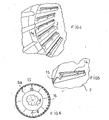
- suitable tongues 14 are present inside the drying chamber 3, i.e. inside the rotating drum put in movement to the motors 13, to present suitable tongues 14 to spread the inert materials which fall down to the cavities 15 placed inside the rotating drum.
- the drying chamber infact, rotates around the own axis longitudinally bringing to a fixed distributor the material that comes inside of longitudinal cavities 15 placed in parallel long the own inside surface.
- the contents of said cavities i.e. the inert materials, fall in the low part of the rotating drum.
- the poured material to the cavities 15 meets the tongue 14 that spreads the inert material forming a thin layer of material inside the cylinder forming the drying chamber 3.
- the material spread in the falling flow from the upper part of the rotating drum to the tongue 14 better holds the hot smokes inside the drying chamber and in the same time the material placed in rotation and poured is heating.
- the new emission material parts are often those with bigger humidity containment.
- the function of the tongues 16 is so that to increase the permanence time and, such as those tongues 16 are in projection from the inside surface of the rotating drum, they bring those parts of new emission material in surface in comparison to the flow material that flows inside of the inner concavities of the cylinders, whereas the material goes on toward the outlet at the end of the plant, from the part of the burner.
- the invented apparatus is illustrated in a merely indicative and not limiting way in the drawings of sheets 1, 2 and 3.
- sheet 1 figure 1 is longitudinal section view of a plant to dry inert materials, to recycle asphalt and to produce with other mixing machineries bituminous conglomerates.
- sheet 2 figure 2 is section view of the invented apparatus.
- Figure 3 is lateral view of the same apparatus.
- figure 4 is inside view of the tongues placed into the rotating drum to spread the inert material produced inside the plant.
- Figure 5 is perspective view of the tongue 14 with cavity 15 carrying the material.
- the figure 6 is section view showing the tongues 16 angulated in comparison to the material flow coming down to the plant.
Abstract
Description
- It is known that the apparatuses for recycling asphalt are largely formed of coaxial cylinders that have in their inside two separated chambers: the drying chamber and, in the bigger cylinder, the combustion chamber. The axis of the coaxial cylinders, such as the plant accessorial elements, are angled of some degrees in comparison with the horizontal line to permit to the material flow in working inside the cylinders to move itself in the slope direction. Moreover, the drying chamber is in rotation to favour the heating and the mixing of the inert materials and of the recycling material introduced from the top in the plant. With the words recycling material is meant the materials coming to the demolition of previous wearing courses, introduced inside the bigger cylinder to an upper opening. Moreover the combustion chamber has at its inside a burner placed downstairs of the plant that, in central area, generates a flame so to heat the introduced materials. The heating of the materials till the compound formation downstairs of the plant is necessary to have the fluid vein of the melted inert materials and melted recycled materials. The aggregate of bitumen with the recycled material determines, after to be positioned onto the street in construction and by use of other engines, the new wearing course. The invented apparatus consists of a apparatus for recycling asphalt with a particular orifice plate according to claim 1, separating the combustion chamber to the drying chamber and the other components, able to increase the plant productivity and also to permit the use of bigger quantity of recycled material with consequent decrease of the costs of the actuated new wearing course. The apparatus is so able to use bigger quantity of material to be worked and to have a large adaptability to the necessities of the different asphalting engines. Different plants are known, as for instance the plant described in the
patent US-A-4 207 062 . Said plant has an orifice plate, to separate the combustion chamber to the drying chamber, with fixing openings to permit the hot gas crossing from the combustion chamber to the drying chamber. Said openings, being fixed onto the orifice plate, do not permit to regulate the oxigen quantity into the combustion chamber and, consequently, to regulate the temperature into the said combustion chamber. The invented apparatus consists of an orifice place 1 according to claim 1 separating the combustion chamber 2 to thedrying chamber 3 and placed between these two chambers of any kind ofplant 4 to recycle the asphalt with production, at the end, of inert materials and recycled materials mixed for the bituminous conglomerate plants. Said orifice plate 1 equipped, onto the ledging part to the burner flame, offixing elements 5 able to permit the assembling of one or more affixingstructures 6, in truncated cone shape or in shape of nozzle, in shape continuity with the same orifice plate 1 and so to help the slippage of the air flow passing inside. Moreover onto the outside conical part of the orifice plate 1 and of thestructures 6 are present ledges 6A with angle of about 45° in comparison with the longitudinal axis so to direct the flow of the recycled materials and to permit its falling, with the rotation given to other parts connected to the affixingstructures 6 and to the orifice plate 1, in parts of the combustion chamber not under the orifice plate 1 and thestructure 6. Saidstructures 6, to be added to the plant on the base of the production necessities, have an opening toward the burner flame that comes to tighten on the base of the number and/or dimension of the elements of the affixingstructure 6. Thetruncate cone structures 6 added to the orifice plate 1 are so to realize a restriction of the air flow placed through the burner and the outlet given to thestack 7. The air flow passes from thedrying chamber 3 to the combustion chamber 2 crossing thecentral opening 8 of the affixingstructures 6 and coming to form, in relation to the actuated restriction, a Venturi effect before coming inside the combustion chamber 2. It is to consider that the affixingstructures 6 permit to extend the conicity in the requested dimension for bigger quantity of working material also maintaining unchanged the other parts of the plants. Infact, having actuated thecentral opening 8 more narrow, the air flow inside the plant is accelerated. So coming air more quickly is increased also the oxygen quantity presents in the combustion chamber and the flame, generated to the burner, reaches higher temperatures. The higher temperature inside the combustion chamber permits an use of bigger quantity of recycled material so like an increasing of the plant productivity. The affixingstructure 6, connected to the orifice plate 1 by thefixing elements 5, are so provided in numbers and dimensions in relation to the plant productive capacity wanted, considering the increasing of the air flow on the base of the product quantity wanted and the end of the same plant. The orifice plate 1 and the affixing structure orstructures 6 are put in rotation such as they are connected with thedrying chamber 3 puts in movement by outside motors. Moreover, the orifice plate 1 has on its level border, placed previous the truncate cone ledging structure or ogival one, ofopenings 9 to permit the air passage at high temperatures from the combustion chamber 2 to thedrying chamber 3. Saidopenings 9, realized boring the structure long thevertical wall 10, have an important rule such as, since in combustion chamber there is a considerable increasing of the temperature with relative increasing of the pressure, saidopenings 9 permit, through the air flow with opposite direction in comparison with the central one that goes to feed the burner flame, to bring air and smokes with high temperature to the drying chamber. Moreover, said air and said smokes, passing through theopenings 9 placed onto the metallic structure of the truncate cone orifice plate 1, heat the same structure brings the same to a high temperature. The recycling material, coming to the inlet hopper 11 placed over the combustion chamber, infact, tends to attach to theoutside surface 12 of the orifice plate 1 and to the outside surface of the affixingstructures 6 if these parts are not at high temperature. It is to consider that the material coming to the hopper 11 and that falling down for gravity inside the combustion chamber 2, if it comes to attach to the walls of theoutside surface 12, generates stoppage and it limits the inlet carrying of the material. Theopenings 9 so permit to have the orifice plate 1, theelements affixing structures 6 with high temperature in the particular parts so avoiding the adhesion of the worked recycling material. It is to be noted that the hopper 11 is placed in correspondence of the orifice plate 1 so that the ledging part of said orifice plate avoids the direct radiation of the flame onto in inlet material which will determine the material fusion in the inlet hole and so stoppage to the hopper and to the underlying parts. The hopper 11 in this position permits, moreover, to have more time for the drying of the inert materials coming to thechamber 3 and to mix in more homogeneous way the recycled materials with the inert materials. Infact, the hopper disposition in this position permits to better eliminate the humidity in these materials when these are melted to the high temperatures create and to the more time of remaining inside the combustion chamber. Then, complementary, inside thedrying chamber 3, i.e. inside the rotating drum put in movement to themotors 13, are presentsuitable tongues 14 to spread the inert materials which fall down to thecavities 15 placed inside the rotating drum. The drying chamber, infact, rotates around the own axis longitudinally bringing to a fixed distributor the material that comes inside oflongitudinal cavities 15 placed in parallel long the own inside surface. At a determined height the contents of said cavities, i.e. the inert materials, fall in the low part of the rotating drum. During the falling the poured material to thecavities 15 meets thetongue 14 that spreads the inert material forming a thin layer of material inside the cylinder forming thedrying chamber 3. The material spread in the falling flow from the upper part of the rotating drum to thetongue 14 better holds the hot smokes inside the drying chamber and in the same time the material placed in rotation and poured is heating. Moreover, to facilitate the drying and to eliminate the humidity dangerous to the formation of the bituminous conglomerate and to extend the permanence time inside the apparatus, in the inside part of the combustion chamber, also this in rotation in this part, are placed crowds oftongues 16, perpendicular to the inside surface of the rotating drum and placed with incidence angle long the material flow direction so to slow the flow same. The surface of these tongues that meet the flow is, infact, angulated in such a way to bring again at the beginning of the plant the elements forming the material of new emission and of bigger dimension. Said elements of bigger dimension heavier are pushed in contrary direction to the flow directs to the end of the plant by the surface of the tongues and increase their time of permanence inside the plant. Moreover, the new emission material parts are often those with bigger humidity containment. The function of thetongues 16 is so that to increase the permanence time and, such as thosetongues 16 are in projection from the inside surface of the rotating drum, they bring those parts of new emission material in surface in comparison to the flow material that flows inside of the inner concavities of the cylinders, whereas the material goes on toward the outlet at the end of the plant, from the part of the burner. The invented apparatus is illustrated in a merely indicative and not limiting way in the drawings ofsheets 1, 2 and 3. In sheet 1figure 1 is longitudinal section view of a plant to dry inert materials, to recycle asphalt and to produce with other mixing machineries bituminous conglomerates. In sheet 2figure 2 is section view of the invented apparatus.Figure 3 is lateral view of the same apparatus. Insheet 3figure 4 is inside view of the tongues placed into the rotating drum to spread the inert material produced inside the plant.Figure 5 is perspective view of thetongue 14 withcavity 15 carrying the material. Thefigure 6 is section view showing thetongues 16 angulated in comparison to the material flow coming down to the plant.
Claims (5)
- Apparatus for recycling asphalt for production of plants of bituminous conglomerate comprising a drying chamber (3), a combustion chamber (2) and an orifice plate (1) separating said drying chamber (3) and said combustion chamber (2) characterized in that one or more affixing structures (6) in truncated cone or nozzle shape are connected fixing elements (5) in shape continuity to said orifice plate (1), to realize a restriction of the air flow from the drying chamber (3) to the combustion chamber (2), so that they form, in relation to the actuated restriction of the air flow, a Venturi effect to the combustion chamber (2) and increase the oxygen quantity present in the combustion chamber (2) thereby increasing the temperature of the burner flame.
- Apparatus, according to previous claim, characterized in that the structures (6) are provided in number and dimension on the base of the plant productive capacity wanted.
- Apparatus, according to claims 1 or 2, where said orifice plate (1) has openings (9) along its vertical wall (10) to bring air and smoke with high temperature to the drying chamber (3) in order to heat both the structures (6) and the orifice plate (1) thereby avoiding the adhesion of the recycled material onto the surfaces and near the structures (6) and the orifice plate (1).
- Apparatus, according to the previous claims, characterized to have tongues (14) to pour inert materials that fall into cavities (15) placed inside the rotating drum forming the drying chamber (3).
- Apparatus, according to the previous claims, characterized to have crowds of tongues (16), perpendicular to the inside surface of the rotating drum and placed with incidence angle long the material flow direction, so to slow the flow of the materials going downward in the plant and to increase the permanence inside the combustion chamber (2).
Priority Applications (6)
| Application Number | Priority Date | Filing Date | Title |
|---|---|---|---|
| PL04425607T PL1624109T3 (en) | 2004-08-03 | 2004-08-03 | Apparatus for recycling asphalt for production plants of bitumimous conglomerate |
| AT04425607T ATE429543T1 (en) | 2004-08-03 | 2004-08-03 | DEVICE FOR REPROCESSING ASPHALT IN BITUMEN CONGLOMERATE PRODUCTION PLANT |
| ES04425607T ES2326478T3 (en) | 2004-08-03 | 2004-08-03 | APPARATUS FOR RECYCLING ASPHALT FOR BITUMINOUS CONGLOMERATE PRODUCTION FACILITIES. |
| DE602004020755T DE602004020755D1 (en) | 2004-08-03 | 2004-08-03 | Apparatus for recycling asphalt in bituminous conglomerate production plants |
| EP04425607A EP1624109B1 (en) | 2004-08-03 | 2004-08-03 | Apparatus for recycling asphalt for production plants of bitumimous conglomerate |
| SI200431184T SI1624109T1 (en) | 2004-08-03 | 2004-08-03 | Apparatus for recycling asphalt for production plants of bitumimous conglomerate |
Applications Claiming Priority (1)
| Application Number | Priority Date | Filing Date | Title |
|---|---|---|---|
| EP04425607A EP1624109B1 (en) | 2004-08-03 | 2004-08-03 | Apparatus for recycling asphalt for production plants of bitumimous conglomerate |
Publications (2)
| Publication Number | Publication Date |
|---|---|
| EP1624109A1 EP1624109A1 (en) | 2006-02-08 |
| EP1624109B1 true EP1624109B1 (en) | 2009-04-22 |
Family
ID=34932700
Family Applications (1)
| Application Number | Title | Priority Date | Filing Date |
|---|---|---|---|
| EP04425607A Not-in-force EP1624109B1 (en) | 2004-08-03 | 2004-08-03 | Apparatus for recycling asphalt for production plants of bitumimous conglomerate |
Country Status (6)
| Country | Link |
|---|---|
| EP (1) | EP1624109B1 (en) |
| AT (1) | ATE429543T1 (en) |
| DE (1) | DE602004020755D1 (en) |
| ES (1) | ES2326478T3 (en) |
| PL (1) | PL1624109T3 (en) |
| SI (1) | SI1624109T1 (en) |
Cited By (2)
| Publication number | Priority date | Publication date | Assignee | Title |
|---|---|---|---|---|
| WO2011004316A1 (en) * | 2009-07-09 | 2011-01-13 | S.I.M. - Societa' Italiana Macchine S.P.A. | Rotary drier for plants for the production of bituminous macadams with the use of recycled materials |
| US8993932B2 (en) | 2009-07-09 | 2015-03-31 | Ammann Italy S.P.A. | Rotary drier for plants for the production of bituminous macadams with the use of recycled materials |
Families Citing this family (5)
| Publication number | Priority date | Publication date | Assignee | Title |
|---|---|---|---|---|
| IT1399864B1 (en) * | 2010-05-07 | 2013-05-09 | Visani | DRYER CYLINDER FOR INCOMBUSIOUS SMOKE REDUCTION |
| ITBO20110307A1 (en) * | 2011-05-27 | 2012-11-28 | Ghirardelli Stefano | DRYER FOR A SYSTEM FOR THE CONSTRUCTION OF BITUMINOUS CONGLOMERATES. |
| ITMI20111353A1 (en) * | 2011-07-20 | 2013-01-21 | Bernardi Impianti Internat S P A | ROTARY CYLINDER DRYER FOR MIXTURES OF VIRGIN INERTES AND RECOVERY MATERIALS FOR THE PREPARATION OF BITUMINOUS CONGLOMERATES |
| ITMI20111352A1 (en) * | 2011-07-20 | 2013-01-21 | Bernardi Impianti Internationl S P A | ROTARY CYLINDER DRYER FOR MIXTURES OF VIRGIN INERTES AND RECOVERY MATERIALS FOR THE PREPARATION OF BITUMINOUS CONGLOMERATES |
| WO2013064851A1 (en) | 2011-11-03 | 2013-05-10 | Visani Roberto | Drying cylinder for blasting of the unburnt smokes |
Family Cites Families (3)
| Publication number | Priority date | Publication date | Assignee | Title |
|---|---|---|---|---|
| US4143972A (en) * | 1978-02-21 | 1979-03-13 | Boeing Construction Equipment Company | Combustion control system for bituminous drum mixers |
| US4207062A (en) * | 1978-05-26 | 1980-06-10 | Moench Frank F | Heating and mixing apparatus for asphaltic pavement |
| US4919538A (en) * | 1989-07-26 | 1990-04-24 | Swisher Jr George W | Drum mixer having a combined mixing and heating zone |
-
2004
- 2004-08-03 AT AT04425607T patent/ATE429543T1/en not_active IP Right Cessation
- 2004-08-03 DE DE602004020755T patent/DE602004020755D1/en active Active
- 2004-08-03 EP EP04425607A patent/EP1624109B1/en not_active Not-in-force
- 2004-08-03 SI SI200431184T patent/SI1624109T1/en unknown
- 2004-08-03 PL PL04425607T patent/PL1624109T3/en unknown
- 2004-08-03 ES ES04425607T patent/ES2326478T3/en active Active
Cited By (5)
| Publication number | Priority date | Publication date | Assignee | Title |
|---|---|---|---|---|
| WO2011004316A1 (en) * | 2009-07-09 | 2011-01-13 | S.I.M. - Societa' Italiana Macchine S.P.A. | Rotary drier for plants for the production of bituminous macadams with the use of recycled materials |
| EP2281944A1 (en) * | 2009-07-09 | 2011-02-09 | S.I.M. Societa Italiana Macchine | Rotary drier for plants for the production of bituminous macadams with the use of recycled materials |
| CN102472021A (en) * | 2009-07-09 | 2012-05-23 | 安曼意大利股份公司 | Rotary drier for plants for the production of bituminous macadams with the use of recycled materials |
| US8993931B2 (en) | 2009-07-09 | 2015-03-31 | Ammann Italy S.P.A. | Rotary drier for plants for the production of bituminous macadams with the use of recycled materials |
| US8993932B2 (en) | 2009-07-09 | 2015-03-31 | Ammann Italy S.P.A. | Rotary drier for plants for the production of bituminous macadams with the use of recycled materials |
Also Published As
| Publication number | Publication date |
|---|---|
| PL1624109T3 (en) | 2009-11-30 |
| EP1624109A1 (en) | 2006-02-08 |
| SI1624109T1 (en) | 2009-12-31 |
| DE602004020755D1 (en) | 2009-06-04 |
| ES2326478T3 (en) | 2009-10-13 |
| ATE429543T1 (en) | 2009-05-15 |
Similar Documents
| Publication | Publication Date | Title |
|---|---|---|
| CA2133949C (en) | Counterflow drum mixer for making asphaltic concrete and methods of operation | |
| CA2667921C (en) | Burner with means for changing the direction of fuel flow | |
| EP1624109B1 (en) | Apparatus for recycling asphalt for production plants of bitumimous conglomerate | |
| US20070070801A1 (en) | Pre-combustion mix drum | |
| US4143972A (en) | Combustion control system for bituminous drum mixers | |
| US5143534A (en) | Heat processing of particulate material with a quenching gas which swirls around the processing zone | |
| US3954390A (en) | Method for producing aggregate used in hardening compositions, predominantly concretes, a fluidized-bed kiln for calcining mineral stock by means of same method, and an aggregate produced by same method | |
| CS212708B2 (en) | Method of and apparatus for heat treatment of finely grained materials | |
| ITMI20082312A1 (en) | DRYER FOR INERT | |
| CS223966B2 (en) | Method of baking the lime and device for executing the said method | |
| US4177080A (en) | Method and apparatus for recycling asphalt-aggregate compositions | |
| US2451582A (en) | Apparatus for producing mineral wool | |
| USRE31905E (en) | Method and apparatus for recycling asphalt-aggregate compositions | |
| EP1477734A2 (en) | Heating device | |
| CN100478613C (en) | Device and method for combustion of fuel | |
| EP1477736A1 (en) | Heating Device | |
| DE2427958B2 (en) | Burners for fluidized bed furnaces | |
| KR102217892B1 (en) | Melting Device For Road Lane Paint | |
| DE4026876C2 (en) | Device on a shaft furnace to form a mixture of combustion air and industrial dust intended for blowing into the oxidation zone of the shaft furnace | |
| SE442241B (en) | PROCEDURE FOR HEATING AND MERGING NON-IRON MATERIALS AND BURNER FOR IMPLEMENTATION OF THE PROCEDURE | |
| RU2525960C2 (en) | Method of gas combustion in burners of ignition furnaces of sinter machines and device for its implementation | |
| JPH11263642A (en) | Double cylinder type firing furnace and firing method | |
| DE1508517A1 (en) | Method and device for calcining refractory materials | |
| JP4332621B2 (en) | Vertical firing furnace and firing method | |
| EP0548154B1 (en) | Method and furnace for preparing a melt for mineral fibre production |
Legal Events
| Date | Code | Title | Description |
|---|---|---|---|
| PUAI | Public reference made under article 153(3) epc to a published international application that has entered the european phase |
Free format text: ORIGINAL CODE: 0009012 |
|
| AK | Designated contracting states |
Kind code of ref document: A1 Designated state(s): AT BE BG CH CY CZ DE DK EE ES FI FR GB GR HU IE IT LI LU MC NL PL PT RO SE SI SK TR |
|
| AX | Request for extension of the european patent |
Extension state: AL HR LT LV MK |
|
| AKX | Designation fees paid | ||
| REG | Reference to a national code |
Ref country code: DE Ref legal event code: 8566 |
|
| 17P | Request for examination filed |
Effective date: 20061020 |
|
| RBV | Designated contracting states (corrected) |
Designated state(s): AT BE BG CH CY CZ DE DK EE ES FI FR GB GR HU IE IT LI LU MC NL PL PT RO SE SI SK TR |
|
| 17Q | First examination report despatched |
Effective date: 20070411 |
|
| GRAP | Despatch of communication of intention to grant a patent |
Free format text: ORIGINAL CODE: EPIDOSNIGR1 |
|
| GRAS | Grant fee paid |
Free format text: ORIGINAL CODE: EPIDOSNIGR3 |
|
| GRAA | (expected) grant |
Free format text: ORIGINAL CODE: 0009210 |
|
| AK | Designated contracting states |
Kind code of ref document: B1 Designated state(s): AT BE BG CH CY CZ DE DK EE ES FI FR GB GR HU IE IT LI LU MC NL PL PT RO SE SI SK TR |
|
| REG | Reference to a national code |
Ref country code: GB Ref legal event code: FG4D |
|
| REG | Reference to a national code |
Ref country code: CH Ref legal event code: EP |
|
| REG | Reference to a national code |
Ref country code: IE Ref legal event code: FG4D |
|
| REF | Corresponds to: |
Ref document number: 602004020755 Country of ref document: DE Date of ref document: 20090604 Kind code of ref document: P |
|
| REG | Reference to a national code |
Ref country code: CH Ref legal event code: NV Representative=s name: FIAMMENGHI-FIAMMENGHI |
|
| REG | Reference to a national code |
Ref country code: SE Ref legal event code: TRGR |
|
| NLV1 | Nl: lapsed or annulled due to failure to fulfill the requirements of art. 29p and 29m of the patents act | ||
| REG | Reference to a national code |
Ref country code: ES Ref legal event code: FG2A Ref document number: 2326478 Country of ref document: ES Kind code of ref document: T3 |
|
| PG25 | Lapsed in a contracting state [announced via postgrant information from national office to epo] |
Ref country code: AT Free format text: LAPSE BECAUSE OF FAILURE TO SUBMIT A TRANSLATION OF THE DESCRIPTION OR TO PAY THE FEE WITHIN THE PRESCRIBED TIME-LIMIT Effective date: 20090422 Ref country code: PT Free format text: LAPSE BECAUSE OF FAILURE TO SUBMIT A TRANSLATION OF THE DESCRIPTION OR TO PAY THE FEE WITHIN THE PRESCRIBED TIME-LIMIT Effective date: 20090822 |
|
| PG25 | Lapsed in a contracting state [announced via postgrant information from national office to epo] |
Ref country code: NL Free format text: LAPSE BECAUSE OF FAILURE TO SUBMIT A TRANSLATION OF THE DESCRIPTION OR TO PAY THE FEE WITHIN THE PRESCRIBED TIME-LIMIT Effective date: 20090422 |
|
| REG | Reference to a national code |
Ref country code: PL Ref legal event code: T3 |
|
| PG25 | Lapsed in a contracting state [announced via postgrant information from national office to epo] |
Ref country code: CZ Free format text: LAPSE BECAUSE OF FAILURE TO SUBMIT A TRANSLATION OF THE DESCRIPTION OR TO PAY THE FEE WITHIN THE PRESCRIBED TIME-LIMIT Effective date: 20090422 Ref country code: RO Free format text: LAPSE BECAUSE OF FAILURE TO SUBMIT A TRANSLATION OF THE DESCRIPTION OR TO PAY THE FEE WITHIN THE PRESCRIBED TIME-LIMIT Effective date: 20090422 Ref country code: EE Free format text: LAPSE BECAUSE OF FAILURE TO SUBMIT A TRANSLATION OF THE DESCRIPTION OR TO PAY THE FEE WITHIN THE PRESCRIBED TIME-LIMIT Effective date: 20090422 Ref country code: DK Free format text: LAPSE BECAUSE OF FAILURE TO SUBMIT A TRANSLATION OF THE DESCRIPTION OR TO PAY THE FEE WITHIN THE PRESCRIBED TIME-LIMIT Effective date: 20090422 |
|
| PG25 | Lapsed in a contracting state [announced via postgrant information from national office to epo] |
Ref country code: SK Free format text: LAPSE BECAUSE OF FAILURE TO SUBMIT A TRANSLATION OF THE DESCRIPTION OR TO PAY THE FEE WITHIN THE PRESCRIBED TIME-LIMIT Effective date: 20090422 Ref country code: BE Free format text: LAPSE BECAUSE OF FAILURE TO SUBMIT A TRANSLATION OF THE DESCRIPTION OR TO PAY THE FEE WITHIN THE PRESCRIBED TIME-LIMIT Effective date: 20090422 |
|
| PLBE | No opposition filed within time limit |
Free format text: ORIGINAL CODE: 0009261 |
|
| STAA | Information on the status of an ep patent application or granted ep patent |
Free format text: STATUS: NO OPPOSITION FILED WITHIN TIME LIMIT |
|
| 26N | No opposition filed |
Effective date: 20100125 |
|
| PG25 | Lapsed in a contracting state [announced via postgrant information from national office to epo] |
Ref country code: MC Free format text: LAPSE BECAUSE OF NON-PAYMENT OF DUE FEES Effective date: 20090831 Ref country code: BG Free format text: LAPSE BECAUSE OF FAILURE TO SUBMIT A TRANSLATION OF THE DESCRIPTION OR TO PAY THE FEE WITHIN THE PRESCRIBED TIME-LIMIT Effective date: 20090722 |
|
| PG25 | Lapsed in a contracting state [announced via postgrant information from national office to epo] |
Ref country code: GR Free format text: LAPSE BECAUSE OF FAILURE TO SUBMIT A TRANSLATION OF THE DESCRIPTION OR TO PAY THE FEE WITHIN THE PRESCRIBED TIME-LIMIT Effective date: 20090723 |
|
| PGFP | Annual fee paid to national office [announced via postgrant information from national office to epo] |
Ref country code: IE Payment date: 20100730 Year of fee payment: 7 |
|
| PGFP | Annual fee paid to national office [announced via postgrant information from national office to epo] |
Ref country code: SI Payment date: 20100730 Year of fee payment: 7 Ref country code: TR Payment date: 20100730 Year of fee payment: 7 |
|
| PGFP | Annual fee paid to national office [announced via postgrant information from national office to epo] |
Ref country code: PL Payment date: 20100730 Year of fee payment: 7 |
|
| PG25 | Lapsed in a contracting state [announced via postgrant information from national office to epo] |
Ref country code: LU Free format text: LAPSE BECAUSE OF NON-PAYMENT OF DUE FEES Effective date: 20090803 |
|
| PG25 | Lapsed in a contracting state [announced via postgrant information from national office to epo] |
Ref country code: HU Free format text: LAPSE BECAUSE OF FAILURE TO SUBMIT A TRANSLATION OF THE DESCRIPTION OR TO PAY THE FEE WITHIN THE PRESCRIBED TIME-LIMIT Effective date: 20091023 |
|
| PG25 | Lapsed in a contracting state [announced via postgrant information from national office to epo] |
Ref country code: CY Free format text: LAPSE BECAUSE OF FAILURE TO SUBMIT A TRANSLATION OF THE DESCRIPTION OR TO PAY THE FEE WITHIN THE PRESCRIBED TIME-LIMIT Effective date: 20090422 |
|
| REG | Reference to a national code |
Ref country code: SI Ref legal event code: KO00 Effective date: 20120307 |
|
| REG | Reference to a national code |
Ref country code: IE Ref legal event code: MM4A |
|
| PG25 | Lapsed in a contracting state [announced via postgrant information from national office to epo] |
Ref country code: SI Free format text: LAPSE BECAUSE OF NON-PAYMENT OF DUE FEES Effective date: 20110804 |
|
| PG25 | Lapsed in a contracting state [announced via postgrant information from national office to epo] |
Ref country code: IE Free format text: LAPSE BECAUSE OF NON-PAYMENT OF DUE FEES Effective date: 20110803 |
|
| PG25 | Lapsed in a contracting state [announced via postgrant information from national office to epo] |
Ref country code: PL Free format text: LAPSE BECAUSE OF NON-PAYMENT OF DUE FEES Effective date: 20110803 |
|
| REG | Reference to a national code |
Ref country code: PL Ref legal event code: LAPE |
|
| PG25 | Lapsed in a contracting state [announced via postgrant information from national office to epo] |
Ref country code: TR Free format text: LAPSE BECAUSE OF NON-PAYMENT OF DUE FEES Effective date: 20110803 |
|
| PGFP | Annual fee paid to national office [announced via postgrant information from national office to epo] |
Ref country code: SE Payment date: 20130902 Year of fee payment: 10 |
|
| PGFP | Annual fee paid to national office [announced via postgrant information from national office to epo] |
Ref country code: GB Payment date: 20130903 Year of fee payment: 10 Ref country code: FR Payment date: 20130830 Year of fee payment: 10 |
|
| PGFP | Annual fee paid to national office [announced via postgrant information from national office to epo] |
Ref country code: DE Payment date: 20131016 Year of fee payment: 10 |
|
| PGFP | Annual fee paid to national office [announced via postgrant information from national office to epo] |
Ref country code: ES Payment date: 20130930 Year of fee payment: 10 |
|
| REG | Reference to a national code |
Ref country code: CH Ref legal event code: AECN Free format text: DAS PATENT IST AUFGRUND DES WEITERBEHANDLUNGSANTRAGS VOM 14. MAERZ 2014 REAKTIVIERT WORDEN. Ref country code: CH Ref legal event code: PL |
|
| PGFP | Annual fee paid to national office [announced via postgrant information from national office to epo] |
Ref country code: FI Payment date: 20140224 Year of fee payment: 10 Ref country code: CH Payment date: 20140319 Year of fee payment: 10 |
|
| PGFP | Annual fee paid to national office [announced via postgrant information from national office to epo] |
Ref country code: IT Payment date: 20140213 Year of fee payment: 10 |
|
| REG | Reference to a national code |
Ref country code: DE Ref legal event code: R119 Ref document number: 602004020755 Country of ref document: DE |
|
| REG | Reference to a national code |
Ref country code: SE Ref legal event code: EUG Ref country code: CH Ref legal event code: PL |
|
| GBPC | Gb: european patent ceased through non-payment of renewal fee |
Effective date: 20140803 |
|
| PG25 | Lapsed in a contracting state [announced via postgrant information from national office to epo] |
Ref country code: FI Free format text: LAPSE BECAUSE OF NON-PAYMENT OF DUE FEES Effective date: 20140803 Ref country code: LI Free format text: LAPSE BECAUSE OF NON-PAYMENT OF DUE FEES Effective date: 20140831 Ref country code: CH Free format text: LAPSE BECAUSE OF NON-PAYMENT OF DUE FEES Effective date: 20140831 Ref country code: IT Free format text: LAPSE BECAUSE OF NON-PAYMENT OF DUE FEES Effective date: 20140803 |
|
| REG | Reference to a national code |
Ref country code: DE Ref legal event code: R119 Ref document number: 602004020755 Country of ref document: DE Effective date: 20150303 |
|
| PG25 | Lapsed in a contracting state [announced via postgrant information from national office to epo] |
Ref country code: SE Free format text: LAPSE BECAUSE OF NON-PAYMENT OF DUE FEES Effective date: 20140804 |
|
| REG | Reference to a national code |
Ref country code: FR Ref legal event code: ST Effective date: 20150430 |
|
| PG25 | Lapsed in a contracting state [announced via postgrant information from national office to epo] |
Ref country code: GB Free format text: LAPSE BECAUSE OF NON-PAYMENT OF DUE FEES Effective date: 20140803 Ref country code: DE Free format text: LAPSE BECAUSE OF NON-PAYMENT OF DUE FEES Effective date: 20150303 |
|
| PG25 | Lapsed in a contracting state [announced via postgrant information from national office to epo] |
Ref country code: FR Free format text: LAPSE BECAUSE OF NON-PAYMENT OF DUE FEES Effective date: 20140901 |
|
| REG | Reference to a national code |
Ref country code: ES Ref legal event code: FD2A Effective date: 20160105 |
|
| PG25 | Lapsed in a contracting state [announced via postgrant information from national office to epo] |
Ref country code: ES Free format text: LAPSE BECAUSE OF NON-PAYMENT OF DUE FEES Effective date: 20140804 |