EP1623768A1 - Liquid spraying device - Google Patents
Liquid spraying device Download PDFInfo
- Publication number
- EP1623768A1 EP1623768A1 EP05254812A EP05254812A EP1623768A1 EP 1623768 A1 EP1623768 A1 EP 1623768A1 EP 05254812 A EP05254812 A EP 05254812A EP 05254812 A EP05254812 A EP 05254812A EP 1623768 A1 EP1623768 A1 EP 1623768A1
- Authority
- EP
- European Patent Office
- Prior art keywords
- nozzle
- liquid
- spraying device
- high voltage
- liquid spraying
- Prior art date
- Legal status (The legal status is an assumption and is not a legal conclusion. Google has not performed a legal analysis and makes no representation as to the accuracy of the status listed.)
- Withdrawn
Links
- 239000007788 liquid Substances 0.000 title claims abstract description 103
- 238000005507 spraying Methods 0.000 title claims abstract description 42
- 239000000126 substance Substances 0.000 claims abstract description 17
- 238000007599 discharging Methods 0.000 claims abstract description 5
- 230000007246 mechanism Effects 0.000 claims description 8
- 239000007921 spray Substances 0.000 description 31
- 239000006200 vaporizer Substances 0.000 description 10
- 150000002500 ions Chemical class 0.000 description 7
- 238000004659 sterilization and disinfection Methods 0.000 description 5
- 230000000845 anti-microbial effect Effects 0.000 description 4
- 239000002245 particle Substances 0.000 description 4
- 239000011941 photocatalyst Substances 0.000 description 4
- 230000001954 sterilising effect Effects 0.000 description 4
- 238000004887 air purification Methods 0.000 description 3
- 238000004332 deodorization Methods 0.000 description 3
- 230000001877 deodorizing effect Effects 0.000 description 3
- 239000011521 glass Substances 0.000 description 3
- GWEVSGVZZGPLCZ-UHFFFAOYSA-N Titan oxide Chemical compound O=[Ti]=O GWEVSGVZZGPLCZ-UHFFFAOYSA-N 0.000 description 2
- 239000012530 fluid Substances 0.000 description 2
- 238000010438 heat treatment Methods 0.000 description 2
- XLYOFNOQVPJJNP-UHFFFAOYSA-N water Substances O XLYOFNOQVPJJNP-UHFFFAOYSA-N 0.000 description 2
- 230000003197 catalytic effect Effects 0.000 description 1
- 239000000470 constituent Substances 0.000 description 1
- 238000010586 diagram Methods 0.000 description 1
- 230000000694 effects Effects 0.000 description 1
- 230000033001 locomotion Effects 0.000 description 1
- 230000004048 modification Effects 0.000 description 1
- 238000012986 modification Methods 0.000 description 1
- 230000001105 regulatory effect Effects 0.000 description 1
- 239000004408 titanium dioxide Substances 0.000 description 1
Images


Classifications
-
- B—PERFORMING OPERATIONS; TRANSPORTING
- B05—SPRAYING OR ATOMISING IN GENERAL; APPLYING FLUENT MATERIALS TO SURFACES, IN GENERAL
- B05B—SPRAYING APPARATUS; ATOMISING APPARATUS; NOZZLES
- B05B7/00—Spraying apparatus for discharge of liquids or other fluent materials from two or more sources, e.g. of liquid and air, of powder and gas
- B05B7/02—Spray pistols; Apparatus for discharge
- B05B7/08—Spray pistols; Apparatus for discharge with separate outlet orifices, e.g. to form parallel jets, i.e. the axis of the jets being parallel, to form intersecting jets, i.e. the axis of the jets converging but not necessarily intersecting at a point
- B05B7/0869—Spray pistols; Apparatus for discharge with separate outlet orifices, e.g. to form parallel jets, i.e. the axis of the jets being parallel, to form intersecting jets, i.e. the axis of the jets converging but not necessarily intersecting at a point the liquid or other fluent material being sucked or aspirated from an outlet orifice by another fluid, e.g. a gas, coming from another outlet orifice
-
- B—PERFORMING OPERATIONS; TRANSPORTING
- B05—SPRAYING OR ATOMISING IN GENERAL; APPLYING FLUENT MATERIALS TO SURFACES, IN GENERAL
- B05B—SPRAYING APPARATUS; ATOMISING APPARATUS; NOZZLES
- B05B5/00—Electrostatic spraying apparatus; Spraying apparatus with means for charging the spray electrically; Apparatus for spraying liquids or other fluent materials by other electric means
- B05B5/001—Electrostatic spraying apparatus; Spraying apparatus with means for charging the spray electrically; Apparatus for spraying liquids or other fluent materials by other electric means incorporating means for heating or cooling, e.g. the material to be sprayed
-
- B—PERFORMING OPERATIONS; TRANSPORTING
- B05—SPRAYING OR ATOMISING IN GENERAL; APPLYING FLUENT MATERIALS TO SURFACES, IN GENERAL
- B05B—SPRAYING APPARATUS; ATOMISING APPARATUS; NOZZLES
- B05B5/00—Electrostatic spraying apparatus; Spraying apparatus with means for charging the spray electrically; Apparatus for spraying liquids or other fluent materials by other electric means
- B05B5/025—Discharge apparatus, e.g. electrostatic spray guns
- B05B5/03—Discharge apparatus, e.g. electrostatic spray guns characterised by the use of gas, e.g. electrostatically assisted pneumatic spraying
Definitions
- the present invention relates to a liquid spraying device which atomizes a liquid chemical for deodorization, sterilization, air purification, antimicrobial treatment, smear resistance or similar purposes and discharges it into the air.
- This liquid spraying device comprises a liquid tank accommodating a liquid to be vaporized such as water, a liquid pipe conduit of which one end is inserted into the liquid tank, a pump intervening on the liquid pipe conduit, a vaporizer whose inlet is connected to the other end of the liquid pipe conduit, a first nozzle connected to the outlet of the vaporizer, a spray liquid tank accommodating a spray liquid (deodorizing liquid), a spray liquid pipe conduit of which one end is inserted into the spray liquid tank, a second nozzle connected to the other end of the spray liquid pipe conduit, and an electrode arranged ahead of the second nozzle.
- the vaporizer is provided with an electric heater and a porous element. The liquid to be vaporized fed into the porous element is heated by the electric heater and thereby vaporized, and the resultant vapor is jetted out from the outlet of the vaporizer.
- This type of liquid spraying device is known as a two-fluid spraying device, which sprays a spray liquid (deodorizing liquid) in the following manner.
- a spray liquid deodorizing liquid
- the liquid to be vaporized in the liquid tank is pumped into the heated porous element in the vaporizer, the liquid is vaporized by heating, and the resultant vapor is jetted out from the tip of the first nozzle.
- the spray liquid in the spray liquid tank instantly as it is caused by this jet vapor to be sucked up by the tip of the second nozzle, collides with the jet vapor to be atomized and blown out forward.
- Liquid chemicals that can be sprayed by using such a liquid spraying device not only include chemicals intended for sterilization or deodorization but also are joined in recent years by ones effective for air purification, antimicrobial treatment, thorough or substantial disinfection, smear resistance, defogging or similar purposes.
- These chemicals include photocatalyst solutions containing titanium dioxide. Since such photocatalyst solutions exert their effect with the catalytic action of light, they are required to stick well to the wall or glass surface.
- Conventional liquid spraying devices electrically charge either positively or negatively the particulates discharged by applying a high voltage with an electrode to contact the particulates discharged into the air with odoriferous matter at high efficiency.
- the conventional liquid spraying devices do not provide sufficient sticking of the spray to the wall surface or the like, and accordingly are required to be improved in the sticking performance of the spray.
- An object of the present invention is to provide a liquid spraying device enabling particulates in a liquid chemical such as a photocatalyst solution sprayed into space to stick well to the wall surface or the like.
- a liquid spraying device comprises a first nozzle for jetting out air or vapor at high speed and a second nozzle for discharging a liquid chemical formed into particulates by a negative pressure created by the air or vapor jetted out of the first nozzle, the first nozzle and the second nozzle being formed of conducting members in at least the tips thereof, the liquid spraying device being further provided with an electrode for short-circuiting the conducting part of the first nozzle and the conducting part of the second nozzle and a DC high voltage generator for applying a DC high voltage to the electrode, wherein particulates discharged from the second nozzle are loaded with positive or negative electric charges by the application of the DC high voltage.
- particulates of liquid chemical can be efficiently loaded with positive or negative electric charges by the application of the DC high voltage generated by the DC high voltage generator to the electrode short-circuiting the conducting part of the first nozzle and the conducting part of the second nozzle. This serves to improve the contact of the particulates of the liquid chemical with odoriferous matter and their sticking to the wall surface, glass surface or the like.
- a liquid spraying device comprises a first nozzle for jetting out air or vapor at high speed and a second nozzle for discharging a liquid chemical, formed into particulates by a negative pressure created by the air or vapor jetted out of the first nozzle, the first nozzle and the second nozzle being formed of conducting members in at least the tips thereof, the liquid spraying device being further provided with a DC high voltage generator for applying a DC high voltage to either the first nozzle or the second nozzle, wherein particulates discharged from the second nozzle are loaded with positive or negative electric charges by the application of the DC high voltage.
- particulates of liquid chemical can be efficiently loaded with positive or negative electric charges by the application of the DC high voltage to either the first nozzle or the second nozzle. This serves to improve the contact of the particulates of the liquid chemical with odoriferous matter and their sticking to the wall surface, glass surface or the like.
- Fig. 1 shows an external perspective view of the liquid spraying device
- Fig. 2 a profile of the same.
- a liquid spraying device 1 is provided with a main unit 100 and a base 200 with a rotating mechanism for rotating the main unit 100 in the horizontal direction as shown in Fig. 1.
- the main unit 100 is provided with a case whose front face slightly bulges forward.
- a spray outlet 111 is formed near the upper central part of the front face of the case, and a control unit 112 including a power switch is arranged toward one side of the front face of the case.
- the base 200 is provided with a thin cylindrical case 210, of which the upper face is circular and the lower face is open, a bottom plate (not shown) and handles 211 fitted to the bottom plate and arranged on the right and left sides of the case 210.
- a rotation shaft (not shown) provided on the bottom plate is connected to the inside center of the case 210.
- a motor (not shown) for rotating the case 210 is connected to the bottom plate. By driving this motor, the main unit 100 is rotated in the horizontal direction integrally together with the case 210.
- the rotating may either be unidirectional or reciprocating (in so-called swinging motions) within a range of a prescribed angle (e.g. about 300 degrees).
- the main unit 100 is connected to the case 210 via a fitting member 300 with an elevation angle adjusting mechanism as shown in Fig. 2.
- the fitting member 300 is provided with a spindle 310 extending in the horizontal direction, a support 320 on which both ends of the spindle 310 pivot, and a supporting plate 330 whose end turnably pivots on the spindle 310 and which is fixed to the rear face of the main unit 100. This arrangement makes the elevation angle of the main unit 100 variable.
- Fig. 3 illustrates the configuration of the spraying mechanism of the liquid spraying device.
- the main unit 100 of the liquid spraying device 1, as shown in Fig. 3, is provided with a liquid tank 101 accommodating a liquid to be vaporized F1, such as water; a liquid pipe conduit 102 of which one end is inserted into the liquid tank 101; a pump 103 intervening on the liquid pipe conduit 102; a vaporizer 104 whose inlet is connected to the other end of the liquid pipe conduit 102; a first nozzle 105 connected to the outlet of the vaporizer 104; a spray liquid tank 106 accommodating a spray liquid (liquid chemical) F2; a spray liquid pipe conduit 107 of which one end is inserted into the spray liquid tank 106; a second nozzle 108 connected to the other end of the spray liquid pipe conduit 107; an electrode 109 arranged from the first nozzle 105 to the second nozzle 108; an electric wire 110 connected to a part of the electrode 109 near the second nozzle 108, and a minus ion generator 400 connected to the electric wire 110.
- the vaporizer 104 is provided with an electric heater 104a and a porous element (not shown).
- the liquid F1 fed into the porous element is heated by the electric heater 104a thereby vaporized, and the resultant vapor is jetted out from the outlet of the vaporizer 104.
- the spray liquid (liquid chemical) F2 can be selected from photocatalyst solutions effective for air purification, antimicrobial treatment, thorough or substantial disinfection, smear resistance or defogging in addition to ones intended for sterilization or deodorization.
- the main unit 100 of this liquid spraying device 1 is known as a two-fluid spraying device, which sprays the spray liquid (liquid chemical) F2 in the following manner.
- the liquid F1 in the liquid tank 101 is fed by the action of the pump 103 into the heated porous element in the vaporizer 104 in a heated state, the liquid F1 is vaporized by heating, and the resultant vapor is jetted out from the tip of the first nozzle 105.
- the spray liquid F2 in the spray liquid tank 106 instantly as it is sucked up by the tip of the second nozzle 108, collides with the jet vapor and is thereby atomized and blown out forward.
- At least the outer faces of the tips of the first nozzle 105 and the second nozzle 108 are conductive. Further, the first nozzle 105 and the second nozzle 108 are electrically short-circuited by the electrode 109. This configuration causes the particulates of the spray liquid F2 sprayed from the second nozzle are minus-ionized by a high DC voltage supplied from the minus ion generator 400.
- a DC high voltage generator is used as the minus ion generator 400.
- the minus ion generator 400 supplies the electrode 109 with a DC high voltage by converting a DC supplied from a power supply unit 401 into an AC with a switching circuit 410, an oscillator 420 and a switching transformer 430, and further rectifying it into a DC and raising its voltage with a Cockcroft-Walton voltage multiplier 440.
- the particulates of the spray liquid F2 sprayed from the second nozzle are thereby minus-ionized.
- the output voltage of the minus ion generator 400 it is preferable for the output voltage of the minus ion generator 400 to be 2000 V to 10000 V, and even more preferable to be 3000 V to 4000 V. In this embodiment of the invention, the output voltage is supposed to be 3600 V.
- the sprayed particulates are minus-ionized by the minus ion generator 400 in this liquid spraying device 1, their sticking to the wall surface or the like is strengthened, and their deodorizing, sterilizing, air purifying and antimicrobial effects can be thereby enhanced. Moreover, as the whole main unit 100 is rotated in the horizontal direction and its elevation angle is adjustable, the liquid can be uniformly sprayed throughout the interior space of the room.
- the electric wire 110 is connected to a part of the electrode 109 near the second nozzle 108 in this embodiment, it may as well be connected near the first nozzle 105 or near the middle part between the first nozzle 105 and the second nozzle 108.
- the minus-ionization of the vapor of the liquid F1 can minus-ionize the particles of the spray liquid F2 indirectly. Therefore, this alternative would be suitable where a spray liquid F2 to which a high DC voltage cannot be directly applied is to be used.
- the electric charge of the particles of the spray liquid F2 can be regulated by adjusting the connecting position.
- the electric wire 110 may as well be applied to either the first nozzle 105 or the second nozzle 108 without providing the electrode 109.
- the electric wire 110 is connected to the second nozzle 108, the sprayed particulates can be efficiently minus-ionized.
- the electric wire 110 is connected to the first nozzle 105, the minus-ionization of the vapor of the liquid F1 can minus-ionize the particles of the spray liquid F2 indirectly. Therefore, this alternative would be suitable where a spray liquid F2 to which a high DC voltage cannot be directly applied is to be used.
- one main unit 100 is provided for one base 200 with a rotating mechanism
- two main units 100 are to be disposed, for instance, they can be arranged back to back on the base 200 so that each main unit 100 sprays the liquid in the reverse direction to the other.
- the particles of the spray liquid F2 are minus-ionized in the foregoing embodiment, they may as well be plus-ionized.
Landscapes
- Disinfection, Sterilisation Or Deodorisation Of Air (AREA)
- Electrostatic Spraying Apparatus (AREA)
Abstract
A liquid spraying device provided with a first nozzle (105) for jetting out air or vapor at high speed and a second nozzle (108) for discharging a liquid chemical (F2), formed into particulates by a negative pressure created by the air or vapor jetted out of the first nozzle (105), further provided with an electrode (109) for short-circuiting the first nozzle (105) and the second nozzle (108) and a minus ion generator (400) for applying a DC high voltage to the electrode (109).
Description
- The present invention relates to a liquid spraying device which atomizes a liquid chemical for deodorization, sterilization, air purification, antimicrobial treatment, smear resistance or similar purposes and discharges it into the air.
- Known liquid spraying devices of this kind include what is disclosed in Japanese Patent Publication 2002-216933. This liquid spraying device comprises a liquid tank accommodating a liquid to be vaporized such as water, a liquid pipe conduit of which one end is inserted into the liquid tank, a pump intervening on the liquid pipe conduit, a vaporizer whose inlet is connected to the other end of the liquid pipe conduit, a first nozzle connected to the outlet of the vaporizer, a spray liquid tank accommodating a spray liquid (deodorizing liquid), a spray liquid pipe conduit of which one end is inserted into the spray liquid tank, a second nozzle connected to the other end of the spray liquid pipe conduit, and an electrode arranged ahead of the second nozzle. The vaporizer is provided with an electric heater and a porous element. The liquid to be vaporized fed into the porous element is heated by the electric heater and thereby vaporized, and the resultant vapor is jetted out from the outlet of the vaporizer.
- This type of liquid spraying device is known as a two-fluid spraying device, which sprays a spray liquid (deodorizing liquid) in the following manner. When the liquid to be vaporized in the liquid tank is pumped into the heated porous element in the vaporizer, the liquid is vaporized by heating, and the resultant vapor is jetted out from the tip of the first nozzle. The spray liquid in the spray liquid tank, instantly as it is caused by this jet vapor to be sucked up by the tip of the second nozzle, collides with the jet vapor to be atomized and blown out forward.
- Liquid chemicals that can be sprayed by using such a liquid spraying device not only include chemicals intended for sterilization or deodorization but also are joined in recent years by ones effective for air purification, antimicrobial treatment, thorough or substantial disinfection, smear resistance, defogging or similar purposes. These chemicals include photocatalyst solutions containing titanium dioxide. Since such photocatalyst solutions exert their effect with the catalytic action of light, they are required to stick well to the wall or glass surface.
- Conventional liquid spraying devices electrically charge either positively or negatively the particulates discharged by applying a high voltage with an electrode to contact the particulates discharged into the air with odoriferous matter at high efficiency. However, the conventional liquid spraying devices do not provide sufficient sticking of the spray to the wall surface or the like, and accordingly are required to be improved in the sticking performance of the spray.
- An object of the present invention is to provide a liquid spraying device enabling particulates in a liquid chemical such as a photocatalyst solution sprayed into space to stick well to the wall surface or the like.
- In order to achieve this object, a liquid spraying device according to the invention comprises a first nozzle for jetting out air or vapor at high speed and a second nozzle for discharging a liquid chemical formed into particulates by a negative pressure created by the air or vapor jetted out of the first nozzle, the first nozzle and the second nozzle being formed of conducting members in at least the tips thereof, the liquid spraying device being further provided with an electrode for short-circuiting the conducting part of the first nozzle and the conducting part of the second nozzle and a DC high voltage generator for applying a DC high voltage to the electrode, wherein particulates discharged from the second nozzle are loaded with positive or negative electric charges by the application of the DC high voltage.
- According to the invention, particulates of liquid chemical can be efficiently loaded with positive or negative electric charges by the application of the DC high voltage generated by the DC high voltage generator to the electrode short-circuiting the conducting part of the first nozzle and the conducting part of the second nozzle. This serves to improve the contact of the particulates of the liquid chemical with odoriferous matter and their sticking to the wall surface, glass surface or the like.
- Or a liquid spraying device according to the invention comprises a first nozzle for jetting out air or vapor at high speed and a second nozzle for discharging a liquid chemical, formed into particulates by a negative pressure created by the air or vapor jetted out of the first nozzle, the first nozzle and the second nozzle being formed of conducting members in at least the tips thereof, the liquid spraying device being further provided with a DC high voltage generator for applying a DC high voltage to either the first nozzle or the second nozzle, wherein particulates discharged from the second nozzle are loaded with positive or negative electric charges by the application of the DC high voltage.
- According to the invention, particulates of liquid chemical can be efficiently loaded with positive or negative electric charges by the application of the DC high voltage to either the first nozzle or the second nozzle. This serves to improve the contact of the particulates of the liquid chemical with odoriferous matter and their sticking to the wall surface, glass surface or the like.
- Other objects, configurative features and advantages of the invention will become more apparent from the following detailed description.
- Fig. 1 shows an external perspective view of a liquid spraying device;
- Fig. 2 shows a profile of the liquid spraying device;
- Fig. 3 shows the configuration of an essential part of the liquid spraying device; and
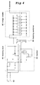
- Fig. 4 is a circuit diagram of a minus ion generator.
- A liquid spraying device, which is a preferred embodiment of the present invention, will be described below with reference to the accompanying drawings. Fig. 1 shows an external perspective view of the liquid spraying device, and Fig. 2, a profile of the same.
- A
liquid spraying device 1 is provided with amain unit 100 and abase 200 with a rotating mechanism for rotating themain unit 100 in the horizontal direction as shown in Fig. 1. Themain unit 100 is provided with a case whose front face slightly bulges forward. Aspray outlet 111 is formed near the upper central part of the front face of the case, and acontrol unit 112 including a power switch is arranged toward one side of the front face of the case. - The
base 200 is provided with a thincylindrical case 210, of which the upper face is circular and the lower face is open, a bottom plate (not shown) and handles 211 fitted to the bottom plate and arranged on the right and left sides of thecase 210. A rotation shaft (not shown) provided on the bottom plate is connected to the inside center of thecase 210. Further, a motor (not shown) for rotating thecase 210 is connected to the bottom plate. By driving this motor, themain unit 100 is rotated in the horizontal direction integrally together with thecase 210. The rotating may either be unidirectional or reciprocating (in so-called swinging motions) within a range of a prescribed angle (e.g. about 300 degrees). - The
main unit 100 is connected to thecase 210 via afitting member 300 with an elevation angle adjusting mechanism as shown in Fig. 2. Thefitting member 300 is provided with aspindle 310 extending in the horizontal direction, asupport 320 on which both ends of thespindle 310 pivot, and a supportingplate 330 whose end turnably pivots on thespindle 310 and which is fixed to the rear face of themain unit 100. This arrangement makes the elevation angle of themain unit 100 variable. - Next, the spraying mechanism of the
main unit 100 of theliquid spraying device 1 will be described with reference to Fig. 3. Fig. 3 illustrates the configuration of the spraying mechanism of the liquid spraying device. - The
main unit 100 of theliquid spraying device 1, as shown in Fig. 3, is provided with aliquid tank 101 accommodating a liquid to be vaporized F1, such as water; aliquid pipe conduit 102 of which one end is inserted into theliquid tank 101; apump 103 intervening on theliquid pipe conduit 102; avaporizer 104 whose inlet is connected to the other end of theliquid pipe conduit 102; afirst nozzle 105 connected to the outlet of thevaporizer 104; a sprayliquid tank 106 accommodating a spray liquid (liquid chemical) F2; a sprayliquid pipe conduit 107 of which one end is inserted into the sprayliquid tank 106; asecond nozzle 108 connected to the other end of the sprayliquid pipe conduit 107; anelectrode 109 arranged from thefirst nozzle 105 to thesecond nozzle 108; anelectric wire 110 connected to a part of theelectrode 109 near thesecond nozzle 108, and aminus ion generator 400 connected to theelectric wire 110. Thevaporizer 104 is provided with anelectric heater 104a and a porous element (not shown). The liquid F1 fed into the porous element is heated by theelectric heater 104a thereby vaporized, and the resultant vapor is jetted out from the outlet of thevaporizer 104. The spray liquid (liquid chemical) F2 can be selected from photocatalyst solutions effective for air purification, antimicrobial treatment, thorough or substantial disinfection, smear resistance or defogging in addition to ones intended for sterilization or deodorization. - The
main unit 100 of thisliquid spraying device 1 is known as a two-fluid spraying device, which sprays the spray liquid (liquid chemical) F2 in the following manner. When the liquid F1 in theliquid tank 101 is fed by the action of thepump 103 into the heated porous element in thevaporizer 104 in a heated state, the liquid F1 is vaporized by heating, and the resultant vapor is jetted out from the tip of thefirst nozzle 105. The spray liquid F2 in thespray liquid tank 106, instantly as it is sucked up by the tip of thesecond nozzle 108, collides with the jet vapor and is thereby atomized and blown out forward. - At least the outer faces of the tips of the
first nozzle 105 and thesecond nozzle 108 are conductive. Further, thefirst nozzle 105 and thesecond nozzle 108 are electrically short-circuited by theelectrode 109. This configuration causes the particulates of the spray liquid F2 sprayed from the second nozzle are minus-ionized by a high DC voltage supplied from theminus ion generator 400. - A DC high voltage generator is used as the
minus ion generator 400. As shown in Fig. 4, theminus ion generator 400 supplies theelectrode 109 with a DC high voltage by converting a DC supplied from a power supply unit 401 into an AC with aswitching circuit 410, anoscillator 420 and aswitching transformer 430, and further rectifying it into a DC and raising its voltage with a Cockcroft-Waltonvoltage multiplier 440. The particulates of the spray liquid F2 sprayed from the second nozzle are thereby minus-ionized. Incidentally, since these constituent circuits are known ones, their description will be dispensed with here. It is preferable for the output voltage of theminus ion generator 400 to be 2000 V to 10000 V, and even more preferable to be 3000 V to 4000 V. In this embodiment of the invention, the output voltage is supposed to be 3600 V. - Since the sprayed particulates are minus-ionized by the
minus ion generator 400 in thisliquid spraying device 1, their sticking to the wall surface or the like is strengthened, and their deodorizing, sterilizing, air purifying and antimicrobial effects can be thereby enhanced. Moreover, as the wholemain unit 100 is rotated in the horizontal direction and its elevation angle is adjustable, the liquid can be uniformly sprayed throughout the interior space of the room. - To add, the embodiment of the invention described above is only illustrative but not limitative. The scope of the invention is stated in the appended claims, and all modifications covered by the meaning of the claims are included in the invention.
- For instance, although the
electric wire 110 is connected to a part of theelectrode 109 near thesecond nozzle 108 in this embodiment, it may as well be connected near thefirst nozzle 105 or near the middle part between thefirst nozzle 105 and thesecond nozzle 108. When it is to be connected near the first nozzle, the minus-ionization of the vapor of the liquid F1 can minus-ionize the particles of the spray liquid F2 indirectly. Therefore, this alternative would be suitable where a spray liquid F2 to which a high DC voltage cannot be directly applied is to be used. Or when theelectric wire 110 is to be connected near the middle part of the electrode, the electric charge of the particles of the spray liquid F2 can be regulated by adjusting the connecting position. - Further, though a DC high voltage is applied to both the
first nozzle 105 and thesecond nozzle 108 in the foregoing embodiment by short-circuiting thefirst nozzle 105 and thesecond nozzle 108 with theelectrode 109, theelectric wire 110 may as well be applied to either thefirst nozzle 105 or thesecond nozzle 108 without providing theelectrode 109. In this case, if theelectric wire 110 is connected to thesecond nozzle 108, the sprayed particulates can be efficiently minus-ionized. On the other hand, if theelectric wire 110 is connected to thefirst nozzle 105, the minus-ionization of the vapor of the liquid F1 can minus-ionize the particles of the spray liquid F2 indirectly. Therefore, this alternative would be suitable where a spray liquid F2 to which a high DC voltage cannot be directly applied is to be used. - Furthermore, though one
main unit 100 is provided for onebase 200 with a rotating mechanism, it is also conceivable to provide a plurality ofmain units 100 for asingle base 200 with a rotating mechanism. Where twomain units 100 are to be disposed, for instance, they can be arranged back to back on the base 200 so that eachmain unit 100 sprays the liquid in the reverse direction to the other. - In addition, the particles of the spray liquid F2 are minus-ionized in the foregoing embodiment, they may as well be plus-ionized.
Claims (8)
- A liquid spraying device (1) comprising a first nozzle (105) for jetting out air or vapor at high speed and a second nozzle (108) for discharging a liquid chemical (F2), formed into particulates by a negative pressure created by the air or vapor jetted out of the first nozzle (105),
the first nozzle (105) and the second nozzle (108) being formed of conducting members in at least the tips thereof,
the liquid spraying device (1) being further provided with an electrode (109) for short-circuiting the conducting part of the first nozzle (105) and the conducting part of the second nozzle (108) and a DC high voltage generator (400) for applying a DC high voltage to the electrode (109), wherein:particulates discharged from the second nozzle (108) are loaded with positive or negative electric charges by the application of the DC high voltage. - The liquid spraying device (1), as set forth in Claim 1, wherein:the position of applying said DC high voltage is near the second nozzle (108).
- The liquid spraying device (1), as set forth in Claim 1, wherein:the position of applying said DC high voltage is near the first nozzle (105).
- The liquid spraying device (1), as set forth in Claim 1, wherein:the position of applying said DC high voltage is near the middle point between the first nozzle (105) and the second nozzle (108).
- A liquid spraying device (1) comprising a first nozzle (105) for jetting out air or vapor at high speed and a second nozzle (108) for discharging a liquid chemical (F2), formed into particulates by a negative pressure created by the air or vapor jetted out of the first nozzle (105),
the first nozzle (105) and the second nozzle (108) being formed of conducting members in at least the tips thereof,
the liquid spraying device (1) being further provided with a DC high voltage generator (400) for applying a DC high voltage to either the first nozzle (105) or the second nozzle (108), wherein:particulates discharged from the second nozzle (108) are loaded with positive or negative electric charges by the application of the DC high voltage. - The liquid spraying device (1), as set forth in any of Claims 1 through 5, further provided with:a rotating device (200) for rotating horizontally the direction of spraying the liquid.
- The liquid spraying device (1), as set forth in Claim 6, wherein:one rotating device (200) is provided with a plurality of spraying mechanisms (100).
- The liquid spraying device (1), as set forth in any of Claims 1 through 7, further provided with:an elevation angle adjusting mechanism (300) capable of vertically adjusting the direction of spraying the liquid.
Applications Claiming Priority (2)
| Application Number | Priority Date | Filing Date | Title |
|---|---|---|---|
| JP2004231263 | 2004-08-06 | ||
| JP2005197758A JP2006068726A (en) | 2004-08-06 | 2005-07-06 | Liquid spraying apparatus |
Publications (1)
| Publication Number | Publication Date |
|---|---|
| EP1623768A1 true EP1623768A1 (en) | 2006-02-08 |
Family
ID=35058519
Family Applications (1)
| Application Number | Title | Priority Date | Filing Date |
|---|---|---|---|
| EP05254812A Withdrawn EP1623768A1 (en) | 2004-08-06 | 2005-08-01 | Liquid spraying device |
Country Status (2)
| Country | Link |
|---|---|
| EP (1) | EP1623768A1 (en) |
| JP (1) | JP2006068726A (en) |
Families Citing this family (1)
| Publication number | Priority date | Publication date | Assignee | Title |
|---|---|---|---|---|
| DE102017119462A1 (en) * | 2017-08-25 | 2019-02-28 | Gelupas Gmbh | Dispensing device for spraying a sprayable fluid or powder |
Citations (4)
| Publication number | Priority date | Publication date | Assignee | Title |
|---|---|---|---|---|
| CH217890A (en) * | 1941-02-28 | 1941-11-15 | Hydro Nitro S A | Process for the unipolar ionization of air and the device for carrying out this process. |
| JPH09225353A (en) * | 1996-02-21 | 1997-09-02 | Yuukiyan Kk | Spraying equipment |
| JP2002216933A (en) | 2000-09-26 | 2002-08-02 | Sharp Corp | Ion generator and air conditioner using the same |
| FR2835750A1 (en) * | 2002-02-11 | 2003-08-15 | Herve Duplessy | PROCESS FOR REFRESHING THE AMBIENT AIR BY PERMANENT HORIZONTAL ATOMIZATION OF WATER, ASSISTED BY A CENTRIFUGAL PULSE AIR VENTILATION TO COVER A PROGRAMMABLE SECTOR ZONE ENSURED BY DRIVING A STEP MOTOR |
Family Cites Families (4)
| Publication number | Priority date | Publication date | Assignee | Title |
|---|---|---|---|---|
| FR907459A (en) * | 1941-02-28 | 1946-03-13 | Hydro Nitro S A | Process for the production of ions in air and device for implementing this process |
| JP2549701Y2 (en) * | 1992-04-17 | 1997-09-30 | サンデン株式会社 | Liquid spray device |
| JPH0760166A (en) * | 1993-08-24 | 1995-03-07 | Sanden Corp | Liquid atomizer |
| US5916640A (en) * | 1996-09-06 | 1999-06-29 | Msp Corporation | Method and apparatus for controlled particle deposition on surfaces |
-
2005
- 2005-07-06 JP JP2005197758A patent/JP2006068726A/en active Pending
- 2005-08-01 EP EP05254812A patent/EP1623768A1/en not_active Withdrawn
Patent Citations (4)
| Publication number | Priority date | Publication date | Assignee | Title |
|---|---|---|---|---|
| CH217890A (en) * | 1941-02-28 | 1941-11-15 | Hydro Nitro S A | Process for the unipolar ionization of air and the device for carrying out this process. |
| JPH09225353A (en) * | 1996-02-21 | 1997-09-02 | Yuukiyan Kk | Spraying equipment |
| JP2002216933A (en) | 2000-09-26 | 2002-08-02 | Sharp Corp | Ion generator and air conditioner using the same |
| FR2835750A1 (en) * | 2002-02-11 | 2003-08-15 | Herve Duplessy | PROCESS FOR REFRESHING THE AMBIENT AIR BY PERMANENT HORIZONTAL ATOMIZATION OF WATER, ASSISTED BY A CENTRIFUGAL PULSE AIR VENTILATION TO COVER A PROGRAMMABLE SECTOR ZONE ENSURED BY DRIVING A STEP MOTOR |
Non-Patent Citations (1)
| Title |
|---|
| PATENT ABSTRACTS OF JAPAN vol. 1998, no. 01 30 January 1998 (1998-01-30) * |
Also Published As
| Publication number | Publication date |
|---|---|
| JP2006068726A (en) | 2006-03-16 |
Similar Documents
| Publication | Publication Date | Title |
|---|---|---|
| TWI353889B (en) | Electrostatic atomizer and hot air blower having t | |
| JP6370185B2 (en) | Mist generator | |
| KR20130129060A (en) | A cleaner comprising transducer for mist spray | |
| JP5221942B2 (en) | Electrostatic atomizer and dryer | |
| CN104619356A (en) | Apparatus and method for generating oxidatively and thermally-enhanced treatment liquids | |
| CN102105081A (en) | Hair care device | |
| KR20110048504A (en) | Electrolysis Cells and DC-DC Converters for Portable Nebulizers | |
| JP2011005149A (en) | Ion generator and beauty treatment equipment with the same | |
| JP6465614B2 (en) | Mist generator | |
| JP5988796B2 (en) | Ion generation system | |
| WO2012026277A1 (en) | Scalp care device | |
| WO2010137503A1 (en) | Mist generating device | |
| JP2011004922A (en) | Scalp care device | |
| WO2010087486A1 (en) | Mist generation device | |
| WO2010061753A1 (en) | Hair dryer | |
| KR101459337B1 (en) | Skin beauty treatment device with steam spray having ionizer | |
| CN212378160U (en) | Air conditioner nanometer water ion generation system and air conditioner | |
| JP6552138B2 (en) | Mist generator | |
| JP2018183777A (en) | Mist generator | |
| JPH0760166A (en) | Liquid atomizer | |
| JP4492386B2 (en) | Ion generator | |
| JP2006068726A (en) | Liquid spraying apparatus | |
| JP2018141596A (en) | Air conditioner | |
| CN221951467U (en) | Trigger assembly and sprayer | |
| CN210582336U (en) | Human body dehumidifier with air negative ion |
Legal Events
| Date | Code | Title | Description |
|---|---|---|---|
| PUAI | Public reference made under article 153(3) epc to a published international application that has entered the european phase |
Free format text: ORIGINAL CODE: 0009012 |
|
| AK | Designated contracting states |
Kind code of ref document: A1 Designated state(s): AT BE BG CH CY CZ DE DK EE ES FI FR GB GR HU IE IS IT LI LT LU LV MC NL PL PT RO SE SI SK TR |
|
| AX | Request for extension of the european patent |
Extension state: AL BA HR MK YU |
|
| AKX | Designation fees paid | ||
| REG | Reference to a national code |
Ref country code: DE Ref legal event code: 8566 |
|
| STAA | Information on the status of an ep patent application or granted ep patent |
Free format text: STATUS: THE APPLICATION IS DEEMED TO BE WITHDRAWN |
|
| 18D | Application deemed to be withdrawn |
Effective date: 20060809 |