EP1623508B1 - Subtractive multipath detection method - Google Patents
Subtractive multipath detection method Download PDFInfo
- Publication number
- EP1623508B1 EP1623508B1 EP04729053.1A EP04729053A EP1623508B1 EP 1623508 B1 EP1623508 B1 EP 1623508B1 EP 04729053 A EP04729053 A EP 04729053A EP 1623508 B1 EP1623508 B1 EP 1623508B1
- Authority
- EP
- European Patent Office
- Prior art keywords
- power
- delay profile
- peak
- multipath signals
- delays
- Prior art date
- Legal status (The legal status is an assumption and is not a legal conclusion. Google has not performed a legal analysis and makes no representation as to the accuracy of the status listed.)
- Expired - Lifetime
Links
- 238000001514 detection method Methods 0.000 title description 22
- 230000001934 delay Effects 0.000 claims description 55
- 238000000034 method Methods 0.000 claims description 52
- 238000001914 filtration Methods 0.000 claims description 9
- 230000004044 response Effects 0.000 claims description 6
- 238000005562 fading Methods 0.000 description 9
- 230000008569 process Effects 0.000 description 8
- 238000013459 approach Methods 0.000 description 4
- 238000007796 conventional method Methods 0.000 description 4
- 238000012935 Averaging Methods 0.000 description 3
- 230000003111 delayed effect Effects 0.000 description 3
- 230000015556 catabolic process Effects 0.000 description 2
- 230000001427 coherent effect Effects 0.000 description 2
- 238000006731 degradation reaction Methods 0.000 description 2
- 238000012545 processing Methods 0.000 description 2
- 238000005070 sampling Methods 0.000 description 2
- 238000001228 spectrum Methods 0.000 description 2
- 230000007480 spreading Effects 0.000 description 2
- 230000004913 activation Effects 0.000 description 1
- 230000006399 behavior Effects 0.000 description 1
- 230000008859 change Effects 0.000 description 1
- 230000001955 cumulated effect Effects 0.000 description 1
- 230000007812 deficiency Effects 0.000 description 1
- 238000013461 design Methods 0.000 description 1
- 230000006866 deterioration Effects 0.000 description 1
- 239000000284 extract Substances 0.000 description 1
- 238000009499 grossing Methods 0.000 description 1
- 230000002452 interceptive effect Effects 0.000 description 1
- 238000004519 manufacturing process Methods 0.000 description 1
- 238000012544 monitoring process Methods 0.000 description 1
- 230000000737 periodic effect Effects 0.000 description 1
- 230000000135 prohibitive effect Effects 0.000 description 1
- 230000035945 sensitivity Effects 0.000 description 1
- 238000007493 shaping process Methods 0.000 description 1
- 230000001360 synchronised effect Effects 0.000 description 1
- 238000012360 testing method Methods 0.000 description 1
Images




Classifications
-
- H—ELECTRICITY
- H04—ELECTRIC COMMUNICATION TECHNIQUE
- H04B—TRANSMISSION
- H04B1/00—Details of transmission systems, not covered by a single one of groups H04B3/00 - H04B13/00; Details of transmission systems not characterised by the medium used for transmission
- H04B1/69—Spread spectrum techniques
- H04B1/707—Spread spectrum techniques using direct sequence modulation
- H04B1/7097—Interference-related aspects
- H04B1/7103—Interference-related aspects the interference being multiple access interference
- H04B1/7107—Subtractive interference cancellation
-
- H—ELECTRICITY
- H04—ELECTRIC COMMUNICATION TECHNIQUE
- H04B—TRANSMISSION
- H04B1/00—Details of transmission systems, not covered by a single one of groups H04B3/00 - H04B13/00; Details of transmission systems not characterised by the medium used for transmission
- H04B1/69—Spread spectrum techniques
- H04B1/707—Spread spectrum techniques using direct sequence modulation
- H04B1/7097—Interference-related aspects
- H04B1/711—Interference-related aspects the interference being multi-path interference
- H04B1/7113—Determination of path profile
-
- H—ELECTRICITY
- H04—ELECTRIC COMMUNICATION TECHNIQUE
- H04B—TRANSMISSION
- H04B1/00—Details of transmission systems, not covered by a single one of groups H04B3/00 - H04B13/00; Details of transmission systems not characterised by the medium used for transmission
- H04B1/69—Spread spectrum techniques
- H04B1/707—Spread spectrum techniques using direct sequence modulation
- H04B1/7097—Interference-related aspects
- H04B1/711—Interference-related aspects the interference being multi-path interference
- H04B1/7115—Constructive combining of multi-path signals, i.e. RAKE receivers
- H04B1/7117—Selection, re-selection, allocation or re-allocation of paths to fingers, e.g. timing offset control of allocated fingers
Definitions
- CDMA Code Division Multiple Access
- an information data stream to be transmitted is modulated by a data sequence with a much higher data rate, referred to as a "signature sequence.”
- the signature sequence usually comprises N bits, wherein each of the N bits is denoted as a "chip.”
- multipath fading A well-known source of degradation common to all known wireless multple access systems, particularly in terrestrial environments, is known as "multipath fading.”
- the transmitted signal follows several propagation paths from a transmitter to a receiver, typically as a result of the signal reflecting off one or more objects before arriving at the receiver. Since the various propagation paths of the transmitted signal are of unequal lengths, several copies of the transmitted signal, referred to as "rays,” will arrive at the receiver with varying time delays.
- phase interference between different rays may cause severe fading and result in signal dropout or cancellation.
- a mobile station in a CDMA system is typically equipped with a RAKE receiver for demodulating active channels (i.e., channels carrying control and/or user data) and for compensating for multipath delays.
- the RAKE receiver comprises a number of RAKE fingers and a combiner for combining the output of each of the RAKE fingers.
- each finger of the RAKE receiver must be synchronized with one of the diverse propagation paths of the channel.
- a RAKE receiver with L fingers is able to detect, at most, L copies of the transmitted signal, which are individually despread by the RAKE fingers according to the individual delays and are added coherently in the combiner.
- each despread output from a RAKE finger is multiplied with a complex weight.
- these weights can be set as the complex conjugate of the corresponding coefficient of the channel impulse response at the appropriate delays.
- the channel impulse response must be estimated at the delays, a process which, for example, can be made by a separate algorithm in the digital signal processor.
- the resulting signal will thus comprise a collection of all the time delayed copies of the transmitted signal.
- the relative time delays of the received rays must be determined in order to synchronize the various rays with the corresponding fingers of the RAKE receiver.
- the number and magnitude of the time delays may change, e.g., due to the movement of the mobile station, i.e., variable distance and velocity relative to the transmitting base station and reflecting objects for users in motion.
- movement of the mobile station may cause new channel paths to appear and old channel paths to disappear.
- the mobile station must continuously monitor the signals received along all propagation paths of an active channel in order to search for new, stronger channel paths.
- the multipath time delays must be measured or estimated repeatedly in a fast and accurate manner. Typically, this is performed by a delay estimator.
- the simplest approach to delay estimation is evaluating the impulse response of the channel over the whole range of the possible delays, or the delay spread, of the channel.
- the resulting complex delay profile (CDP) or power delay profile (PDP) may then be subjected to peak detection, and the peak locations are reported to the RAKE as the delay estimates.
- CDP complex delay profile
- PDP power delay profile
- typical implementations use shortened search windows, reduced searcher resolution, and additional short sub-searchers to produce higher-resolution estimates of certain areas of the power delay profile.
- a typical approach in the case where several distinct multipath channels with different path structure need to be characterized, includes applying a delay estimation and subsequent channel estimation algorithm to each of these channels.
- FIG. 1 illustrates one conventional approach to delay estimation. Pilot samples received over the air interface are provided to path searcher 101.
- Path searcher 101 computes instantaneous impulse estimates (complex or power) over a range of delays that constitute a significant fraction of the maximal delay spread allowed by the system.
- the complex value or power value for a given delay value is estimated, e.g., by correlating the received data for pilot symbols with an appropriately delayed copy of the spreading sequence.
- the path searcher is employed mainly for detecting the existence of paths and its output resolution may be lower than that required by the RAKE.
- the tuning fingers 103 receive the coarse power delay profile information provided by the path searcher 101 and produce a high-resolution instantaneous complex delay profile or power delay profile over one or several narrow delay windows.
- Path resolution, tracking and reporting block 105 extracts physical path location information from the path searcher 101 and the tuning fingers 103, and presents delay estimates consistently to subsequent RAKE receiver stages. Unchanging assignment of paths to RAKE fingers is necessary to support filtering of power and interference estimation for each finger.
- the degree of complexity of the block 105 can vary significantly depending on system parameters, ranging from simple peak detection to sophisticated deconvolution and filtering.
- Scheduling and window placement block 107 determines the timing of activation of the path searcher 101 and the tuning fingers 103, and their window positions for each cycle.
- the timing may be fixed (periodic) or depends on signals derived from the environment, while the positioning usually depends on the location of previously detected paths.
- channel estimation for the reported delays is performed by tuning despreaders to these delays and using the despread pilot symbols to deduce the complex path coefficient for a given delay.
- a variety of filtering or smoothing methods may be applied to these instantaneous estimates, in order to improve the quality of the channel estimates. These methods are well known in the art.
- the complexity of the delay estimation process is significantly higher than that of the channel estimation operation.
- the sensitivity of the delay estimation to low SIR conditions is significantly higher, causing rapid deterioration below a certain threshold, compared to the channel estimation process which degrades more gradually.
- the quality of performance of a RAKE receiver is related to how well the channel delay estimator performs. The more accurate the estimates of signal path delays, the better the RAKE receiver will perform.
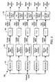
- An exemplary channel delay estimator 200 is illustrated in FIG. 2 .
- the channel delay estimator 200 tests different delay versions of the received signal for correlation with a given spreading sequence. For each hypothesized delay, the degree of correlation determines whether the hypothesized delay represents an actual delay experienced by the received signal. To carry out this process, the exemplary channel delay estimator 200 has five "probing fingers", each associated with one of the hypothesized delays: t 0 , t 1 , t 2 , t 3 , t 4 .
- ⁇ t By making ⁇ t small, it is possible to fine tune a delay estimate and track changes in the delay.
- the choice of five probing fingers in this example is merely for illustration: The number of probing fingers in any particular embodiment is a design choice that can be less than, equal to, or greater than five.
- the received signal is supplied to a delay unit 201 that aligns the signal to be processed in accordance with the hypothesized delay.
- the (delayed) received signal is then passed through a matched filter or correlator 203.
- the matched filter 203 generates an estimate of the impulse response of the channel. This estimate is generally a complex-valued signal.
- the estimates, made for each of the number N of time slots may be summed non-coherently. This means that the absolute value of the complex signal is determined (block 205), and then summed with the values obtained for the signal during other time slots (summing block 207). Alternatively, if the channel parameters are subject to slow changes, then the channel estimates may be summed coherently, so that the absolute value block 205 would not be present. In other alternative embodiments, a combination of coherent and non-coherent averaging is also possible.
- the result of summing blocks 207 for each position (0, ⁇ t, 2 ⁇ t, 3 ⁇ t, 4 ⁇ t) are compared and the position having the highest summed value is selected, as illustrated in FIG. 2 .
- the real-valued summed results for each signal position of the channel delay estimator are fed into a selector.
- the selector determines the position having the highest summed value.
- the parameters associated with this position such as the estimated delay or impulse response, may be used by the RAKE receiver.
- the position parameters may be used by a searcher to synchronize the RAKE receiver to different paths.
- EP 1 126 626 A2 discloses a pattern generation circuit, multi-path detection circuit employing the same and multi-path detection method.
- the multi-path can provides for path detection in the environment where the path is located close in the extent of one chip in the multi-path detection circuit of CDMA type receiver unit.
- a method and apparatus are provided for determining delays of multipath signals.
- a power delay profile comprising at least a first and second multipath signal is received.
- a first peak power value in the power delay profile is detected.
- Power values associated with the first detected peak power value are subtracted from the power delay profile to generate a modified power delay profile.
- a second peak power value in the modified power delay profile is detected.
- Power values associated with the second detected peak power value are subtracted from the modified power delay profile to generate another modified power delay profile.
- the delays associated with the first and second multipath signals are determined by locating a peak power associated with the first and second multipath signals in the another modified power delay profile.
- a first set of delays associated with the first and second multipath signals are determined.
- the first set of delays are determined without accounting for a phase difference between the first and second multipath signals.
- Channel estimation is performed using the determined first set of delays, the channel estimation producing a phase difference between the first and second multipath signals.
- a second set of delays associated with the first and second multipath signals are determined, the second set of delays being determined based on the phase difference produced by the channel estimation.
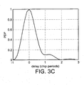
- FIGs. 3A and 3B illustrate two signals which can be received by a RAKE reciever. Assuming that the two signals illustrated in FIGs. 3A and 3B were received at the illustrated time delays, the RAKE reciever would see the signal illustrated in FIG. 3C .
- Conventional techniques for delay detections employ peak detection to estimate the various delay positions. Accordingly, conventional techniques would estimate that the first multipath signal has a delay of 0, while the second multipath signal has a delay of 1.25, i.e., the locations of the peak powers of the signal. However, referring to FIG. 3B it can be seen that the delay associated with the second multipath is 1 chip.
- the peak at 1.25 chips in the multipath signal of FIG. 3C is caused by the power of the sidelobe of the first multipath signal combining with the power of the peak of the second multipath signal. Accordingly, conventional peak detection techniques for delay estimation may produce inaccurate delay estimations when multipath signals are closely spaced.
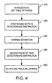
- FIG. 4 illustrates an exemplary method for overcoming the above-identified and other deficiencies of conventional delay estimation techniques in accordance with the present invention.
- the delay detections are improved by minimizing the influences of other mainlobes and sidelobes.
- An initialization phase is performed to generate a table of the ratios of the power of the main peak and the powers of sample positions within several sidelobes (step 410).
- the table can be generated by calculating the power profiles of the despread signals of an isolated path for various noise and fading levels.
- the profiles fluctuate over time, mainly due to the dynamic behavior of the radio channels.
- the shapes of the profiles resemble the convolution of the pulse shaping filters employed in transmitters and receivers, with the difference being that there is a noise floor.
- the ratios of the power of the main peak and the powers of the sample positions within several sidelobes are rather stable.
- the determined ratios are stored in a table in the receiver.
- the generation of the table can be performed when the receiver is first powered up. Alternatively, the table can be generated and installed in the receiver during manufacture.
- FIG. 5A illustrates an exemplary method for performing path detection and subtraction in accordance with the present invention.
- a long time non-coherently accumulated power delay profile is calculated (step 505), and the noise floor is estimated (step 510).
- the noise floor can be estimated by, for example, averaging the powers of a noise finger, or can be inferred from the shape of the main peak and the corresponding detected power values.
- the powers of the sample positions within the predetermined number of sidelobes are subtracted from the power delay profile to generate a new power delay profile (step 520).
- This new power delay profile will not contain the power due to the sidelobes of the Nth highest detected peak.
- the subtraction is performed by multiplying the ratios listed in the table by the difference between the peak power and the noise floor to generate a product, and subtracting the product from the power delay profile.
- N it is determined whether N is equal to a predetermined threshold value (step 525).
- the predetermined threshold value can be based on the number of multipath delay detections desired. Accordingly, the predetermined threshold value can be set equal to the number of fingers employed in the tracking stage of the RAKE receiver.
- N is not equal to the threshold ("No" path out of decision step 525)
- N is incremented by one (step 530)
- the next highest peak N will be detected. It will be recognized that the loop of steps 515-530 will continue to produce a power delay profile with less and less influence to the peak powers from sidelobes of other peak powers.
- the delays of the multipaths are determined as the positions corresponding to the highest powers separated by a minimal distance window.
- the ranges of subtractions should be carefully selected in accordance with the setting of the minimal distance windows. Since the main peak of the power delay profile has a width of approximately one chip, if the minimal distance window is set to a value greater than or equal to one chip, the subtraction of the sidelobes of the already found path will determine the peak position of the next path. If the minimal distance window is set to less than one chip, subtraction of parts of the mainlobe of the already found path becomes significant and should be included in the subtraction process.
- FIGs. 6A-6C illustrate this overestimation.
- the multipath signal illustrated in FIG. 6B is received, and that the signal contains two different paths, path A (with power P A ) and path B (with power P B ). See FIG. 6A .
- the signals will present a waveform at the receiver such as that illustrated in FIG. 6B .
- equation (2) a random phase approximation is applied to equation (2), which results in the total power being the direct summation of the powers of the two paths. Since, at this stage of the method, the power delay profile is accumulated non-coherently, the cosine term in equation (2) cancels.
- the receiver will employ the power value (P A in FIG. 6B ) for the largest peak for the subtraction, which comprises the sum of the power values of paths A and B.
- P A in FIG. 6B the power value for the largest peak for the subtraction
- the waveform illustrated in FIG. 6C results.
- the subtracted peak power of path B is lower than the original peak power due to over-subtraction.
- the method of FIG. 5A can be modified as illustrated in FIG. 5B .
- steps 532-560 are inserted between steps 525 and 565.
- N is set equal to 0 (step 532).
- N is then incremented such that in this first instance the highest peak is employed, and in subsequent iterations the next highest peak is employed (step 540).
- the power difference for the Nth peak between the power delay profile after the sidelobes of the Nth peak is subtracted and the original power profile is calculated (step 550).
- N is equal to the predetermined threshold (step 560). If N is equal to the predetermined threshold ("Yes" path out of decision step 560), then the delays are determined by the highest power separated by minimum distance (step 565) and channel estimation is performed (step 570). If, however, N is not equal to the predetermined threshold ("No" path out of decision step 560), then steps 540-560 are repeated.
- FIG. 5B illustrates only a single iteration of the loop of steps 532-560 for each of the N paths, multiple iterations of the loop for each of the N paths can be performed. In each of the subsequent iterations the estimate of the power values of the peaks will improve.
- phase difference ⁇ in equation (2) can be determined in accordance with techniques well known in the art.
- the path detection is now performed using the method of FIG. 5A , except now the phase difference ⁇ in equation (2) is employed in the delay determinations and subtractions (step 440). Specifcally, the phase difference ⁇ is employed in the subtraction of the Nth highest peak (step 520). By employing the phase difference ⁇ in the subtractions a more accurate estimate can be obtained.
- the recursive subtraction scheme discussed in connection with FIG. 5B can be employed to achieve even more accurate estimations of the peak powers of the multipath signals.
- additional memory space is required to store the power delay profiles during the time that the channel estimate is performed, and to store and process the recursive power subtraction. This may result in latency in the processing of the delay detections.
- steps 532-560 should provide an adequate estimate of the peak powers for the purposes of the RAKE receiver.
- filtering and tracking multipath signals is a conventional technique for RAKE receivers. Accordingly, filtering and tracking can be applied in numerous ways and on one or more sampling points for each path without interfering with the scope of the invention.
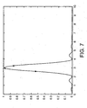
- FIG. 7 illustrates three sampling points subject to filtering and tracking in accordance with exemplary embodiments of the present invention.
- the present invention is equally applicable to any type of multiple access technique which has to contend with multipath signals. Moreover, the present invention is applicable to any type of system in which multipath signals are present and distinguished by the system.
Landscapes
- Engineering & Computer Science (AREA)
- Computer Networks & Wireless Communication (AREA)
- Signal Processing (AREA)
- Position Fixing By Use Of Radio Waves (AREA)
- Mobile Radio Communication Systems (AREA)
Description
- Due to the limited radio spectrum allocated by governmental bodies, various techniques have been employed to allow multiple users to access the allocated radio spectrum. One type of multiple access technique is known as Code Division Multiple Access (CDMA). In systems which operate using CDMA techniques, an information data stream to be transmitted is modulated by a data sequence with a much higher data rate, referred to as a "signature sequence." The signature sequence usually comprises N bits, wherein each of the N bits is denoted as a "chip."
- A well-known source of degradation common to all known wireless multple access systems, particularly in terrestrial environments, is known as "multipath fading." In a multipath environment, the transmitted signal follows several propagation paths from a transmitter to a receiver, typically as a result of the signal reflecting off one or more objects before arriving at the receiver. Since the various propagation paths of the transmitted signal are of unequal lengths, several copies of the transmitted signal, referred to as "rays," will arrive at the receiver with varying time delays. In a multipath fading channel, phase interference between different rays may cause severe fading and result in signal dropout or cancellation.
- A mobile station in a CDMA system is typically equipped with a RAKE receiver for demodulating active channels (i.e., channels carrying control and/or user data) and for compensating for multipath delays. The RAKE receiver comprises a number of RAKE fingers and a combiner for combining the output of each of the RAKE fingers. When demodulating a multipath fading channel, each finger of the RAKE receiver must be synchronized with one of the diverse propagation paths of the channel. A RAKE receiver with L fingers is able to detect, at most, L copies of the transmitted signal, which are individually despread by the RAKE fingers according to the individual delays and are added coherently in the combiner. At the addition performed by the combiner, each despread output from a RAKE finger is multiplied with a complex weight. Typically, these weights can be set as the complex conjugate of the corresponding coefficient of the channel impulse response at the appropriate delays. For this, the channel impulse response must be estimated at the delays, a process which, for example, can be made by a separate algorithm in the digital signal processor. The resulting signal will thus comprise a collection of all the time delayed copies of the transmitted signal.
- The relative time delays of the received rays must be determined in order to synchronize the various rays with the corresponding fingers of the RAKE receiver. Unfortunately, the number and magnitude of the time delays may change, e.g., due to the movement of the mobile station, i.e., variable distance and velocity relative to the transmitting base station and reflecting objects for users in motion. Also, movement of the mobile station may cause new channel paths to appear and old channel paths to disappear. Hence, the mobile station must continuously monitor the signals received along all propagation paths of an active channel in order to search for new, stronger channel paths. To perform this monitoring efficiently, the multipath time delays must be measured or estimated repeatedly in a fast and accurate manner. Typically, this is performed by a delay estimator.
- The simplest approach to delay estimation (DE) is evaluating the impulse response of the channel over the whole range of the possible delays, or the delay spread, of the channel. The resulting complex delay profile (CDP) or power delay profile (PDP) may then be subjected to peak detection, and the peak locations are reported to the RAKE as the delay estimates. However, the processing and power consumption expense of frequently executing this path searching routine is usually prohibitive. Therefore, typical implementations use shortened search windows, reduced searcher resolution, and additional short sub-searchers to produce higher-resolution estimates of certain areas of the power delay profile.
- A typical approach, in the case where several distinct multipath channels with different path structure need to be characterized, includes applying a delay estimation and subsequent channel estimation algorithm to each of these channels.
-
FIG. 1 illustrates one conventional approach to delay estimation. Pilot samples received over the air interface are provided topath searcher 101. Path searcher 101 computes instantaneous impulse estimates (complex or power) over a range of delays that constitute a significant fraction of the maximal delay spread allowed by the system. The complex value or power value for a given delay value is estimated, e.g., by correlating the received data for pilot symbols with an appropriately delayed copy of the spreading sequence. The path searcher is employed mainly for detecting the existence of paths and its output resolution may be lower than that required by the RAKE. - The
tuning fingers 103 receive the coarse power delay profile information provided by thepath searcher 101 and produce a high-resolution instantaneous complex delay profile or power delay profile over one or several narrow delay windows. Path resolution, tracking andreporting block 105 extracts physical path location information from thepath searcher 101 and thetuning fingers 103, and presents delay estimates consistently to subsequent RAKE receiver stages. Unchanging assignment of paths to RAKE fingers is necessary to support filtering of power and interference estimation for each finger. The degree of complexity of theblock 105 can vary significantly depending on system parameters, ranging from simple peak detection to sophisticated deconvolution and filtering. - Scheduling and
window placement block 107 determines the timing of activation of thepath searcher 101 and thetuning fingers 103, and their window positions for each cycle. The timing may be fixed (periodic) or depends on signals derived from the environment, while the positioning usually depends on the location of previously detected paths. - To increase robustness of the delay estimation under various difficult channel conditions (low signal-to-interference ratio (SIR), wide delay spread, closely-spaced paths, etc.), averaging of memory can be added to the algorithms so that the delay estimation process operates across many channel fading cycles and is not significantly affected by the instantaneous fading realization.
- Following delay estimation, channel estimation for the reported delays is performed by tuning despreaders to these delays and using the despread pilot symbols to deduce the complex path coefficient for a given delay. A variety of filtering or smoothing methods may be applied to these instantaneous estimates, in order to improve the quality of the channel estimates. These methods are well known in the art.
- Regardless of the specific implementation, the complexity of the delay estimation process is significantly higher than that of the channel estimation operation. Similarly, the sensitivity of the delay estimation to low SIR conditions is significantly higher, causing rapid deterioration below a certain threshold, compared to the channel estimation process which degrades more gradually.
- It can be appreciated that the quality of performance of a RAKE receiver is related to how well the channel delay estimator performs. The more accurate the estimates of signal path delays, the better the RAKE receiver will perform. An exemplary
channel delay estimator 200 is illustrated inFIG. 2 . Thechannel delay estimator 200 tests different delay versions of the received signal for correlation with a given spreading sequence. For each hypothesized delay, the degree of correlation determines whether the hypothesized delay represents an actual delay experienced by the received signal. To carry out this process, the exemplarychannel delay estimator 200 has five "probing fingers", each associated with one of the hypothesized delays: t0, t1, t2, t3, t4. These could, for example, be equally spaced with respect to one another, such as at 0, Δt, 2Δt, 3Δt, 4Δt, as illustrated inFIG. 2 . As can be appreciated, there will always be some minimal amount of delay, so having t0=0 absolutely may not be physically possible. However, the delay associated with to may be used as a base offset, with each of the hypothesized delays reduced by the base offset amount, making it possible for t0=0 relative to the base offset. By making Δt small, it is possible to fine tune a delay estimate and track changes in the delay. The choice of five probing fingers in this example is merely for illustration: The number of probing fingers in any particular embodiment is a design choice that can be less than, equal to, or greater than five. - The received signal is supplied to a
delay unit 201 that aligns the signal to be processed in accordance with the hypothesized delay. The (delayed) received signal is then passed through a matched filter orcorrelator 203. The matchedfilter 203 generates an estimate of the impulse response of the channel. This estimate is generally a complex-valued signal. - If the channel parameters are subject to fast changes, the estimates, made for each of the number N of time slots, may be summed non-coherently. This means that the absolute value of the complex signal is determined (block 205), and then summed with the values obtained for the signal during other time slots (summing block 207). Alternatively, if the channel parameters are subject to slow changes, then the channel estimates may be summed coherently, so that the
absolute value block 205 would not be present. In other alternative embodiments, a combination of coherent and non-coherent averaging is also possible. - In either case, the result of
summing blocks 207 for each position (0, Δt, 2Δt, 3Δt, 4Δt) are compared and the position having the highest summed value is selected, as illustrated inFIG. 2 . The real-valued summed results for each signal position of the channel delay estimator are fed into a selector. The selector determines the position having the highest summed value. The parameters associated with this position, such as the estimated delay or impulse response, may be used by the RAKE receiver. For example, the position parameters may be used by a searcher to synchronize the RAKE receiver to different paths. - The fact that the channel is fading will prevent every time slot from contributing to the estimate of the delays. However, the variations of the channel in general are such that the fading process is much faster than the changes of the delays. Thus, if we assume merely for the sake of example that, on average, there are two equally strong paths with gain h1 and h2, two peaks will be built up over time in the cumulated sum over different time slots, so long as the delays are sufficiently well separated in time.
-
EP 1 126 626 A2 - Conventional techniques for addressing multipath propagation may not correctly identify the delay of particular paths when the mutual difference in delay between multiple paths is small. These inaccurate delay estimations can cause serious degradation in the performance of the RAKE receiver.
- It should be emphasized that the terms "comprises" and "comprising", when used in this specification, are taken to specify the presence of stated features, integers, steps or components; but the use of these terms does not preclude the presence or addition of one or more other features, integers, steps, components or groups thereof.
- In accordance with exemplary embodiments of the present invention a method and apparatus are provided for determining delays of multipath signals. A power delay profile comprising at least a first and second multipath signal is received. A first peak power value in the power delay profile is detected. Power values associated with the first detected peak power value are subtracted from the power delay profile to generate a modified power delay profile. A second peak power value in the modified power delay profile is detected. Power values associated with the second detected peak power value are subtracted from the modified power delay profile to generate another modified power delay profile. The delays associated with the first and second multipath signals are determined by locating a peak power associated with the first and second multipath signals in the another modified power delay profile. A first set of delays associated with the first and second multipath signals are determined. The first set of delays are determined without accounting for a phase difference between the first and second multipath signals. Channel estimation is performed using the determined first set of delays, the channel estimation producing a phase difference between the first and second multipath signals. A second set of delays associated with the first and second multipath signals are determined, the second set of delays being determined based on the phase difference produced by the channel estimation.
- The objects and advantages of the invention will be understood by reading the following detailed description in conjunction with the drawings in which:
-
FIG. 1 illustrates components employed in a conventional delay estimator. -
FIG. 2 illustrates a conventional delay estimator. -
FIGs. 3A-3C illustrate two multipath signals and the combination of the signals as seen by a receiver. -
FIG. 4 illustrates an exemplary method for delay estimation in accordance with the present invention. -
FIGs. 5A and5B illustrate two exemplary methods for performing path detection and subtraction in accordance with the present invention. -
FIGs. 6A-6C illustrate the contribution from other multipath signals to a multipath signal. -
FIG. 7 illustrates an exemplary multipath signal for which multiple sample points are filtered and tracked in accordance with the present invention. - The various features of the invention will now be described with respect to the figures, in which like parts are identified with the same reference characters.
- Problems encountered using conventional delay estimation techniques will be described in connection with
FIGs. 3A-3C .FIGs. 3A and 3B illustrate two signals which can be received by a RAKE reciever. Assuming that the two signals illustrated inFIGs. 3A and 3B were received at the illustrated time delays, the RAKE reciever would see the signal illustrated inFIG. 3C . Conventional techniques for delay detections employ peak detection to estimate the various delay positions. Accordingly, conventional techniques would estimate that the first multipath signal has a delay of 0, while the second multipath signal has a delay of 1.25, i.e., the locations of the peak powers of the signal. However, referring toFIG. 3B it can be seen that the delay associated with the second multipath is 1 chip. The peak at 1.25 chips in the multipath signal ofFIG. 3C is caused by the power of the sidelobe of the first multipath signal combining with the power of the peak of the second multipath signal. Accordingly, conventional peak detection techniques for delay estimation may produce inaccurate delay estimations when multipath signals are closely spaced. -
FIG. 4 illustrates an exemplary method for overcoming the above-identified and other deficiencies of conventional delay estimation techniques in accordance with the present invention. Generally, the delay detections are improved by minimizing the influences of other mainlobes and sidelobes. An initialization phase is performed to generate a table of the ratios of the power of the main peak and the powers of sample positions within several sidelobes (step 410). The table can be generated by calculating the power profiles of the despread signals of an isolated path for various noise and fading levels. Typically, the profiles fluctuate over time, mainly due to the dynamic behavior of the radio channels. The shapes of the profiles resemble the convolution of the pulse shaping filters employed in transmitters and receivers, with the difference being that there is a noise floor. On average the ratios of the power of the main peak and the powers of the sample positions within several sidelobes are rather stable. The determined ratios are stored in a table in the receiver. The generation of the table can be performed when the receiver is first powered up. Alternatively, the table can be generated and installed in the receiver during manufacture. - After the table has been generated the receiver performs a first stage of path detection and subtraction (step 420).
FIG. 5A illustrates an exemplary method for performing path detection and subtraction in accordance with the present invention. Initially, a long time non-coherently accumulated power delay profile is calculated (step 505), and the noise floor is estimated (step 510). The noise floor can be estimated by, for example, averaging the powers of a noise finger, or can be inferred from the shape of the main peak and the corresponding detected power values. Next, the Nth highest peak in the multipath signal is detected (step 515). Since this is the first iteration of the method, N=1, i.e., the highest peak is detected. - The powers of the sample positions within the predetermined number of sidelobes are subtracted from the power delay profile to generate a new power delay profile (step 520). This new power delay profile will not contain the power due to the sidelobes of the Nth highest detected peak. The subtraction is performed by multiplying the ratios listed in the table by the difference between the peak power and the noise floor to generate a product, and subtracting the product from the power delay profile. After the subtraction, it is determined whether N is equal to a predetermined threshold value (step 525). The predetermined threshold value can be based on the number of multipath delay detections desired. Accordingly, the predetermined threshold value can be set equal to the number of fingers employed in the tracking stage of the RAKE receiver. If N is not equal to the threshold ("No" path out of decision step 525), then N is incremented by one (step 530), and the next highest peak N will be detected. It will be recognized that the loop of steps 515-530 will continue to produce a power delay profile with less and less influence to the peak powers from sidelobes of other peak powers.
- If N is equal to the predetermined threshold value ("Yes" path out of decision step 525), then the delays of the multipaths are determined as the positions corresponding to the highest powers separated by a minimal distance window. In order to properly detect the different multipath signals the ranges of subtractions should be carefully selected in accordance with the setting of the minimal distance windows. Since the main peak of the power delay profile has a width of approximately one chip, if the minimal distance window is set to a value greater than or equal to one chip, the subtraction of the sidelobes of the already found path will determine the peak position of the next path. If the minimal distance window is set to less than one chip, subtraction of parts of the mainlobe of the already found path becomes significant and should be included in the subtraction process.
- The approach mentioned above is good enough to detect peak positions in the cases with little interference between different multipaths. More advanced methods can be developed to deal with more complicated multipath profiles as will be demonstrated below. Since before the subtractions each large detected peak may contain contributions from other multipaths, the subtractions may be overestimated.
FIGs. 6A-6C illustrate this overestimation. Assume that the multipath signal illustrated inFIG. 6B is received, and that the signal contains two different paths, path A (with power PA) and path B (with power PB). SeeFIG. 6A . Since multipath and delay detection has not yet been performed, the signals will present a waveform at the receiver such as that illustrated inFIG. 6B . At each delay value, a received signal with two multipath componentsS 1 andS 2 can generally be expressed as:
- where Sk is the two-dimensional vector with the in-phase component Ik, quadrature component Qk and the power Pk, wherein k=1, 2. The quantity φ represents the phase difference between the two signals. From equation (1) the power of the total signal can be represented by:

- At this stage of the method a random phase approximation is applied to equation (2), which results in the total power being the direct summation of the powers of the two paths. Since, at this stage of the method, the power delay profile is accumulated non-coherently, the cosine term in equation (2) cancels.
- Accordingly, the receiver will employ the power value (PA in
FIG. 6B ) for the largest peak for the subtraction, which comprises the sum of the power values of paths A and B. When the sidelobes of path A are subtracted the waveform illustrated inFIG. 6C results. Clearly, the subtracted peak power of path B is lower than the original peak power due to over-subtraction. - To address this over-subtraction problem, the method of
FIG. 5A can be modified as illustrated inFIG. 5B . Specifically, in the method ofFIG. 5B steps 532-560 are inserted betweensteps - Although
FIG. 5B illustrates only a single iteration of the loop of steps 532-560 for each of the N paths, multiple iterations of the loop for each of the N paths can be performed. In each of the subsequent iterations the estimate of the power values of the peaks will improve. - Returning now to
FIG. 4 , after the first stage of path detection is performed (step 420), channel estimation is performed (step 430). Depending upon how often the channel estimation is performed, the power delay profiles for the same period can be calculated and saved. Using the channel estimate, the phase difference φ in equation (2) can be determined in accordance with techniques well known in the art. The path detection is now performed using the method ofFIG. 5A , except now the phase difference φ in equation (2) is employed in the delay determinations and subtractions (step 440). Specifcally, the phase difference φ is employed in the subtraction of the Nth highest peak (step 520). By employing the phase difference φ in the subtractions a more accurate estimate can be obtained. - In the second stage of path detection the recursive subtraction scheme discussed in connection with
FIG. 5B can be employed to achieve even more accurate estimations of the peak powers of the multipath signals. To perform the recursive subtractions discussed in connection withFIG. 5B additional memory space is required to store the power delay profiles during the time that the channel estimate is performed, and to store and process the recursive power subtraction. This may result in latency in the processing of the delay detections. However, since the sidelobes are much lower than the main peaks, a few iterations of steps 532-560 should provide an adequate estimate of the peak powers for the purposes of the RAKE receiver. Although there is a trade-off between the number of iterations of the recursive subtraction and the accuracy of the subtracted powers, to which the final detections of the multipaths are, in general, not very sensitive. - The results of the second stage of path detections and subtractions are employed in the filtering and tracking of the multipath signals (step 450). In general, filtering and tracking multipath signals is a conventional technique for RAKE receivers. Accordingly, filtering and tracking can be applied in numerous ways and on one or more sampling points for each path without interfering with the scope of the invention.
FIG. 7 illustrates three sampling points subject to filtering and tracking in accordance with exemplary embodiments of the present invention. - Although the exemplary embodiments have been described above in connection with CDMA, it will be recognized that the present invention is equally applicable to any type of multiple access technique which has to contend with multipath signals. Moreover, the present invention is applicable to any type of system in which multipath signals are present and distinguished by the system.
- Thus, the preferred embodiments are merely illustrative and should not be considered restrictive in any way. The scope of the invention is given by the appended claims, rather than the preceding description, and all variations and equivalents which fall within the range of the claims are intended to be embraced therein.
Claims (25)
- A method for determining delays of multipath signals in a RAKE receiver,
the method comprising:receiving a power delay profile comprising at least a first and second multipath signal;detecting (515) a first peak power value of a first peak in the power delay profile;subtracting power values (520) associated with the first detected peak power value from the power delay profile to generate a modified power delay profile;detecting (515, 530) a second peak power value of a second peak in the modified power delay profile;subtracting power values (520, 530) associated with the second detected peak power value from the modified power delay profile to generate another modified power delay profile; anddetermining (535, 565) the delays associated with the first and second multipath signals by locating first and second peak powers associated with the first and second multipath signals in the another modified power delay profile, wherein the determined delays associated with the first and second multipath signals comprise a first set of delays associated with the first and second multipath signals, characterized by:the first set of delays being determined without accounting for a phase difference between the first and second multipath signals, and the method comprising:performing a channel estimation (570) using the determined first set of delays, the channel estimation producing a phase difference between the first and second multipath signals; anddetermining a second set of delays associated with the first and second multipath signals, the second set of delays being determined based on the phase difference produced by the channel estimation. - The method of claim 1, further comprising:detecting (515, 530) a third peak power value in the another modified power delay profile;subtracting (520) power values associated with the third detected peak power value from the another modified power delay profile to generate a third modified power delay profile, wherein the phase difference between the first and second multipath signals is employed in the subtraction;detecting (515, 530) a fourth peak power value in the third modified power delay profile;subtracting (520) power values associated with the fourth detected peak power value from the third modified power delay profile to produce a fourth modified power delay profile, wherein the phase difference between the first and second multipath signals is employed in the subtraction; anddetermining (535, 565) the second set of delays associated with the first and second multipath signals by locating first and second peak powers associated with the first and second multipath signals in the fourth modified power delay profile.
- The method of claim 2, wherein the power values associated with the third and fourth detected peak power values are power values of sidelobes corresponding to the third and fourth detected peak power values.
- The method of claim 2, wherein the power values associated with the third and fourth detected peak power values are power values of sidelobes and part of a mainlobe corresponding to the third and fourth detected peak power values.
- The method of claim 2, wherein the first and third peak power values are peak power values of the first multipath signal, and the second and fourth peak power values are peak power values of the second multipath signal.
- The method of claim 1, wherein the subtracting steps each comprise:determining a difference between the peak power value and a noise floor;multiplying the difference by a ratio to produce a product; andsubtracting the product from the power delay profile at the delay values associated with the peak power value.
- The method of claim 1, further comprising:calculating a difference between a power value at a location of the first detected peak power value in the power delay profile and a power value at the delay values associated with the first detected peak power value in the another modified power delay profile;multiplying the difference by a ratio to generate a product; andadding the product to the modified power delay profile at the location of the first detected peak power value.
- The method of claim 1, further comprising:filtering and tracking peak power values associated with each determined delay.
- The method of claim 8, wherein the filtering and tracking is performed for the peak power values and additional sample points associated with the peak power values.
- The method of claim 1, wherein the power values associated with the first and second detected peak power values are power values of sidelobes corresponding to the first and second detected peak power values.
- The method of claim 1, wherein the power values associated with the first and second detected peak power values are power values of sidelobes and part of a mainlobe corresponding to the first and second detected peak power values.
- The method of claim 1, wherein the first and second detected peak power values are respectively the highest and second highest detected peak power values of the power delay profile.
- The method of claim 1, wherein the first and second set of delays are determined by subtracting sidelobe powers associated with the first and second multipath signals.
- The method of claim 1, wherein the first and second set of delays are determined by subtracting sidelobe and part of mainlobe powers associated with the first and second multipath signals.
- A RAKE receiver comprising:a path searcher configured to receive a power delay profile comprising at least a first and second multipath signal, and to detect (515) a first peak power value of a first peak in the power delay profile; anda channel estimator configured to estimate a response of a channel upon which the multipath signals are received, wherein:said path searcher is configured to:subtract (520) power values associated with the first detected peak power value from the power delay profile to generate a modified power delay profile,detect (515, 530) a second peak power value of a second peak in the modified power delay profile,subtract (520) power values associated with the second detected peak power value from the modified power delay profile to generate another modified power delay profile, anddetermine (535, 565) the delays associated with the first and second multipath signals by locating first and second peak powers associated with the first and second multipath signals in the another modified power delay profile, wherein the determined delays associated with the first and second multipath signals comprise a first set of delays associated with the first and second multipath signals, characterized in thatthe first set of delays are determined without accounting for a phase difference between the first and second multipath signals, in that said channel estimator:is configured to perform a channel estimation (570) using the determined first set of delays, the channel estimation producing a phase difference between the first and second multipath signals, and in thatsaid path searcher:is configured to determine a second set of delays associated with the first and second multipath signals, the second set of delays being determined based on the phase difference produced by the channel estimator.
- The RAKE receiver of claim 15, wherein the path searcher is configured to:detect a third peak power value in the another modified power delay profile,subtract power values associated with the third detected peak power value from the another modified power delay profile to generate a third modified power delay profile,detect a fourth peak power value in the third modified power delay profile, subtracts power values associated with the fourth detected peak power value to produce a fourth modified power delay profile, anddetermine the second set of delays associated with the first and second multipath signals by locating first and second peak powers associated with the first and second multipath signals in the fourth modified power delay profile, wherein the subtraction of power values associated with the third and fourth detected peak power values accounts for the phase difference.
- The RAKE receiver of claim 15, wherein the power values associated with the first and second detected peak power values are power values of sidelobes corresponding to the first and second detected peak power values.
- The RAKE receiver of claim 15, wherein the power values associated with the first and second detected peak power values are power values of sidelobes and part of a mainlobe corresponding to the first and second detected peak power values.
- The RAKE receiver of claim 15, wherein the first and second detected peak power values are respectively the highest and second highest detected peak power values of the power delay profile.
- The RAKE receiver of claim 15, wherein the first and second set of delays are determined by subtracting sidelobe powers associated with the first multipath signal prior to determining the delay associated with the second multipath signal.
- The method of claim 1, wherein the at least a first and second multipath signal includes a plurality of multipath signals, the method further comprising:detecting another peak power value in a most recently generated modified power delay profile;subtracting power values associated with the detected another peak power value and relating to sidelobes of the another peak from a most recently modified power delay profile to generate a new modified power delay profile;repeating the detecting and subtracting steps until a predetermined number of peaks have been detected, where the generated new modified power delay profile from one iteration is the most recently modified power delay profile of the next iteration; anddetermining delays associated with the plurality of multipath signals by locating peak powers associated with the plurality of multipath signals of the most recently generated modified power delay profile.
- The method of claim 21, wherein the peak powers are detected in order of descending powers.
- The method of claim 21, wherein the determined delays associated with the plurality of multipath signals constitute a first set of delays, and the method further comprises:performing a channel estimation using the determined first set of delays, the channel estimation producing phase differences between the plurality of multipath signals; andrepeating the detecting, subtracting and repeating steps, wherein the subtracting step employs the phase differences produced by the channel estimation;and determining a second set of delays associated with the plurality of multipath signals by locating the peak powers associated with the plurality of multipath signals in the most recently generated modified power delay profile.
- The method of claim 23 further comprising iteratively repeating the steps of:detecting another peak power value in a most recently generated modified power delay profile;subtracting power values associated with the detected another peak power value from a most recently modified power delay profile to generate a new modified power delay profile, wherein said power values associated with the detected another peak power value do not include the detected another peak power value and at least one additional power value related to the detected another peak power value;repeating the detecting and subtracting steps until a predetermined number of peaks have been detected, where the generated new modified power delay profile from one iteration is the most recently generated modified power delay profile of the next iteration; anddetermining delays associated with the plurality of multipath signals by locating peak powers associated with the plurality of multipath signals of the most recently generated modified power delay profile.
- The method of claim 23 further comprising iteratively repeating the steps of:repeating the detecting, subtracting and repeating steps, wherein the subtracting step employs the phase differences produced by the channel estimation; anddetermining a second set of delays associated with the plurality of multipath signals by locating the peak powers associated with the plurality of multipath signals in the most recently generated modified power delay profile.
Applications Claiming Priority (2)
| Application Number | Priority Date | Filing Date | Title |
|---|---|---|---|
| US10/437,285 US7116998B2 (en) | 2003-05-14 | 2003-05-14 | Subtractive multipath delay detection |
| PCT/EP2004/004294 WO2004102825A1 (en) | 2003-05-14 | 2004-04-23 | Subtractive multipath detection method |
Publications (2)
| Publication Number | Publication Date |
|---|---|
| EP1623508A1 EP1623508A1 (en) | 2006-02-08 |
| EP1623508B1 true EP1623508B1 (en) | 2015-07-22 |
Family
ID=33417344
Family Applications (1)
| Application Number | Title | Priority Date | Filing Date |
|---|---|---|---|
| EP04729053.1A Expired - Lifetime EP1623508B1 (en) | 2003-05-14 | 2004-04-23 | Subtractive multipath detection method |
Country Status (3)
| Country | Link |
|---|---|
| US (2) | US7116998B2 (en) |
| EP (1) | EP1623508B1 (en) |
| WO (1) | WO2004102825A1 (en) |
Families Citing this family (17)
| Publication number | Priority date | Publication date | Assignee | Title |
|---|---|---|---|---|
| US7356100B2 (en) * | 2003-03-03 | 2008-04-08 | Mitsubishi Electric Research Laboratories, Inc. | Estimating channel impulse response and equalizer coefficients in UWB communication systems |
| US7116998B2 (en) * | 2003-05-14 | 2006-10-03 | Telefonaktiebolaget L M Ericsson (Publ) | Subtractive multipath delay detection |
| US7756191B2 (en) * | 2003-12-22 | 2010-07-13 | Nokia Corporation | Deconvolution searcher for wireless communication system |
| EP1596506B1 (en) * | 2004-05-13 | 2011-11-23 | NTT DoCoMo, Inc. | Path searcher and path searching method in a CDMA receiver |
| JP2006180146A (en) * | 2004-12-22 | 2006-07-06 | Nec Corp | CDMA receiver and path search method used therefor |
| DE102005002801B4 (en) * | 2005-01-20 | 2007-06-14 | Infineon Technologies Ag | Rake finger placement method with reliable path detection |
| CN100531011C (en) * | 2005-07-04 | 2009-08-19 | 上海原动力通信科技有限公司 | Method for defining up-converter channel impact responding and multi-user united detection method |
| EP1894310A1 (en) * | 2005-06-24 | 2008-03-05 | Thomson Licensing | Multipath searcher results sorting method |
| JP2009500592A (en) * | 2005-07-07 | 2009-01-08 | 独立行政法人情報通信研究機構 | Delay calculation apparatus and method |
| US20070021086A1 (en) * | 2005-07-22 | 2007-01-25 | Industrial Technology Research Institute | Method for path selection and signal processing in wireless communications system |
| US7643539B2 (en) * | 2006-04-28 | 2010-01-05 | Alcatel-Lucent Usa Inc. | Multi-path equalizer configuration technique |
| EP1976136A1 (en) * | 2007-03-29 | 2008-10-01 | Telefonaktiebolaget LM Ericsson (publ) | A rake receiver and a method of allocating fingers in a rake receiver |
| CN101022287A (en) * | 2007-04-09 | 2007-08-22 | 互芯集成电路(北京)有限公司 | Multi-path detecting method and receiver in code division multiple access communication system |
| US8599905B2 (en) * | 2008-02-22 | 2013-12-03 | Freescale Semiconductor, Inc. | Processor for use as a path searcher of a spread spectrum receiver and a method of operation of the processor |
| DE102008050455B4 (en) * | 2008-10-08 | 2013-01-31 | Astrium Gmbh | Method for determining position |
| US9020074B2 (en) * | 2010-02-18 | 2015-04-28 | Intel Mobile Communications GmbH | Apparatus and method for antenna diversity reception |
| US10158436B2 (en) * | 2015-02-17 | 2018-12-18 | Mitsubishi Electric Corporation | Receiver apparatus and reception method |
Family Cites Families (37)
| Publication number | Priority date | Publication date | Assignee | Title |
|---|---|---|---|---|
| US106039A (en) * | 1870-08-02 | Improvement in wheel-cultivators | ||
| US28677A (en) * | 1860-06-12 | Improvement in fire-arms | ||
| US114125A (en) * | 1871-04-25 | Improvement in steam-engines | ||
| US159507A (en) * | 1875-02-09 | Improvement in cultivators | ||
| US61056A (en) * | 1867-01-08 | Improved cement composition for pavements, floors, walks | ||
| US131479A (en) * | 1872-09-17 | Improvement in cooking-vessels | ||
| US5305349A (en) * | 1993-04-29 | 1994-04-19 | Ericsson Ge Mobile Communications Inc. | Quantized coherent rake receiver |
| US5572552A (en) * | 1994-01-27 | 1996-11-05 | Ericsson Ge Mobile Communications Inc. | Method and system for demodulation of downlink CDMA signals |
| WO1995034140A1 (en) | 1994-06-03 | 1995-12-14 | Motorola, Inc. | Method and apparatus for cancelling interference in signals having undergone multipath |
| US5764690A (en) * | 1996-06-04 | 1998-06-09 | Motorola, Inc. | Apparatus for despreading and demodulating a burst CDMA signal |
| US6175587B1 (en) * | 1997-12-30 | 2001-01-16 | Motorola, Inc. | Communication device and method for interference suppression in a DS-CDMA system |
| US6363104B1 (en) * | 1998-10-02 | 2002-03-26 | Ericsson Inc. | Method and apparatus for interference cancellation in a rake receiver |
| EP0993127A1 (en) | 1998-10-06 | 2000-04-12 | Texas Instruments Incorporated | Method and apparatus using Walsh-Hadamard transformation for forward link multiuser detection in CDMA systems |
| EP0994570A1 (en) | 1998-10-12 | 2000-04-19 | Sony International (Europe) GmbH | Spread spectrum channel estimator with inter-path interference cancellation |
| JP2002528992A (en) | 1998-10-27 | 2002-09-03 | ローク マナー リサーチ リミテッド | Signal extraction method in CDMA system |
| US6314130B1 (en) * | 1999-04-28 | 2001-11-06 | Dspc Technologies, Ltd. | System and method for joint time tracking of multiple paths |
| US6801565B1 (en) | 1999-06-25 | 2004-10-05 | Ericsson Inc. | Multi-stage rake combining methods and apparatus |
| US6714585B1 (en) | 1999-06-25 | 2004-03-30 | Ericsson Inc. | Rake combining methods and apparatus using weighting factors derived from knowledge of spreading spectrum signal characteristics |
| US6922434B2 (en) * | 1999-10-19 | 2005-07-26 | Ericsson Inc. | Apparatus and methods for finger delay selection in RAKE receivers |
| JP3468189B2 (en) | 2000-02-02 | 2003-11-17 | 日本電気株式会社 | Pattern generation circuit, multipath detection circuit using the same, and multipath detection method thereof |
| US6728324B1 (en) | 2000-07-31 | 2004-04-27 | Rf Micro Devices, Inc. | Method and apparatus for multipath signal compensation in spread-spectrum communications systems |
| US6680727B2 (en) * | 2000-10-17 | 2004-01-20 | Qualcomm Incorporated | Method and apparatus for canceling pilot interference in a CDMA communication system |
| US6865218B1 (en) | 2000-11-27 | 2005-03-08 | Ericsson Inc. | Multipath interference reduction for a CDMA system |
| JP2002232397A (en) | 2001-01-31 | 2002-08-16 | Ntt Docomo Inc | Reception processing method and reception apparatus in mobile communication system |
| JP2002232327A (en) * | 2001-02-05 | 2002-08-16 | Nec Corp | Path selection method and circuit used for receiver |
| US7697594B2 (en) * | 2001-03-30 | 2010-04-13 | Texas Instruments Incorporated | Method and apparatus for regenerative based interference cancellation within a communication system |
| WO2002093764A1 (en) | 2001-05-16 | 2002-11-21 | Siemens Aktiengesellschaft | Device and method for processing cdma-data packets |
| US7170924B2 (en) | 2001-05-17 | 2007-01-30 | Qualcomm, Inc. | System and method for adjusting combiner weights using an adaptive algorithm in wireless communications system |
| JP3558053B2 (en) | 2001-06-06 | 2004-08-25 | 日本電気株式会社 | Adaptive antenna receiver |
| KR100453811B1 (en) * | 2001-11-30 | 2004-10-20 | 한국전자통신연구원 | Apparatus for searching multipath in spread spectrum cummunicatios and method thereof |
| US20030114125A1 (en) * | 2001-12-14 | 2003-06-19 | Essam Sourour | Interference suppression in a radio receiver |
| US7142586B2 (en) * | 2002-09-18 | 2006-11-28 | Telefonaktiebolaget Lm Ericsson (Publ) | Robust delay estimation architecture |
| US7197063B2 (en) * | 2002-09-18 | 2007-03-27 | Telefonaktiebolaget Lm Ericsson (Publ) | Advanced rake delay control |
| US7277474B2 (en) * | 2002-11-05 | 2007-10-02 | Analog Devices, Inc. | Finger allocation for a path searcher in a multipath receiver |
| US20060274819A1 (en) * | 2003-01-30 | 2006-12-07 | Magnus Bengtsson | Truncation and level adjustment of rake output symbols |
| US7356074B2 (en) * | 2003-05-08 | 2008-04-08 | Rf Micro Devices, Inc. | Estimation of multipath channel with sub-chip resolution |
| US7116998B2 (en) * | 2003-05-14 | 2006-10-03 | Telefonaktiebolaget L M Ericsson (Publ) | Subtractive multipath delay detection |
-
2003
- 2003-05-14 US US10/437,285 patent/US7116998B2/en not_active Expired - Fee Related
-
2004
- 2004-04-23 WO PCT/EP2004/004294 patent/WO2004102825A1/en not_active Ceased
- 2004-04-23 EP EP04729053.1A patent/EP1623508B1/en not_active Expired - Lifetime
-
2006
- 2006-09-15 US US11/532,311 patent/US7529554B2/en not_active Expired - Fee Related
Also Published As
| Publication number | Publication date |
|---|---|
| WO2004102825A1 (en) | 2004-11-25 |
| US7116998B2 (en) | 2006-10-03 |
| US7529554B2 (en) | 2009-05-05 |
| EP1623508A1 (en) | 2006-02-08 |
| US20040229637A1 (en) | 2004-11-18 |
| US20070110138A1 (en) | 2007-05-17 |
Similar Documents
| Publication | Publication Date | Title |
|---|---|---|
| US7529554B2 (en) | Subtractive multipath delay detection | |
| CN100464506C (en) | Threshold Setting of Adaptive Path Selection in DS-CDMA Receiver | |
| EP1048127B1 (en) | Method and apparatus for multipath delay estimation in direct sequence spread spectrum communication systems | |
| EP1135911B1 (en) | Method for determining optimum number of complex samples for coherent averaging in a communication system | |
| EP1540843B1 (en) | Robust delay estimation architecture | |
| EP1543634B1 (en) | Assessment of delay estimation quality using interference estimates | |
| US6256338B1 (en) | Method for determining fading correction factor in a communication system | |
| JP2005535176A (en) | Power measurement of received CDMA signal by soft threshold processing after correlation | |
| EP1454421B1 (en) | Interference suppression in a cdma radio receiver | |
| US20080144702A1 (en) | Method of and apparatus for computation of unbiased power delay profile | |
| EP1704652B1 (en) | Method of and apparatus for computation of unbiased power delay profile | |
| CN100518001C (en) | path searcher window positioning method and device | |
| WO2004112269A1 (en) | Positioning a multipath search window | |
| JP4838262B2 (en) | Method and system for estimating delay with minimal finger assignment | |
| EP1487127B1 (en) | Method and apparatus for positioning a multipath search window | |
| US6765951B2 (en) | Method for estimating the channel impulse response of a mobile radio channel | |
| HK1117288A (en) | Method of and system for delay estimation with minimized finger allocation | |
| KR20090045544A (en) | Apparatus and Method for Channel Estimation Using Doppler Estimation in Code Division Multiplexing Systems |
Legal Events
| Date | Code | Title | Description |
|---|---|---|---|
| PUAI | Public reference made under article 153(3) epc to a published international application that has entered the european phase |
Free format text: ORIGINAL CODE: 0009012 |
|
| 17P | Request for examination filed |
Effective date: 20051017 |
|
| AK | Designated contracting states |
Kind code of ref document: A1 Designated state(s): AT BE BG CH CY CZ DE DK EE ES FI FR GB GR HU IE IT LI LU MC NL PL PT RO SE SI SK TR |
|
| DAX | Request for extension of the european patent (deleted) | ||
| RIN1 | Information on inventor provided before grant (corrected) |
Inventor name: ERICSSON, ANDERS Inventor name: WANG, XIAOHUI |
|
| 17Q | First examination report despatched |
Effective date: 20110726 |
|
| RAP1 | Party data changed (applicant data changed or rights of an application transferred) |
Owner name: UNWIRED PLANET, LLC |
|
| RIC1 | Information provided on ipc code assigned before grant |
Ipc: H04B 1/7113 20110101ALI20140204BHEP Ipc: H04B 1/707 20110101AFI20140204BHEP Ipc: H04B 1/7107 20110101ALI20140204BHEP |
|
| RAP1 | Party data changed (applicant data changed or rights of an application transferred) |
Owner name: UNWIRED PLANET INTERNATIONAL LIMITED |
|
| GRAP | Despatch of communication of intention to grant a patent |
Free format text: ORIGINAL CODE: EPIDOSNIGR1 |
|
| INTG | Intention to grant announced |
Effective date: 20150219 |
|
| GRAS | Grant fee paid |
Free format text: ORIGINAL CODE: EPIDOSNIGR3 |
|
| GRAA | (expected) grant |
Free format text: ORIGINAL CODE: 0009210 |
|
| AK | Designated contracting states |
Kind code of ref document: B1 Designated state(s): AT BE BG CH CY CZ DE DK EE ES FI FR GB GR HU IE IT LI LU MC NL PL PT RO SE SI SK TR |
|
| REG | Reference to a national code |
Ref country code: GB Ref legal event code: FG4D |
|
| REG | Reference to a national code |
Ref country code: CH Ref legal event code: EP |
|
| REG | Reference to a national code |
Ref country code: IE Ref legal event code: FG4D |
|
| REG | Reference to a national code |
Ref country code: AT Ref legal event code: REF Ref document number: 738396 Country of ref document: AT Kind code of ref document: T Effective date: 20150815 |
|
| REG | Reference to a national code |
Ref country code: DE Ref legal event code: R096 Ref document number: 602004047533 Country of ref document: DE |
|
| REG | Reference to a national code |
Ref country code: AT Ref legal event code: MK05 Ref document number: 738396 Country of ref document: AT Kind code of ref document: T Effective date: 20150722 |
|
| REG | Reference to a national code |
Ref country code: NL Ref legal event code: MP Effective date: 20150722 |
|
| PG25 | Lapsed in a contracting state [announced via postgrant information from national office to epo] |
Ref country code: FI Free format text: LAPSE BECAUSE OF FAILURE TO SUBMIT A TRANSLATION OF THE DESCRIPTION OR TO PAY THE FEE WITHIN THE PRESCRIBED TIME-LIMIT Effective date: 20150722 Ref country code: GR Free format text: LAPSE BECAUSE OF FAILURE TO SUBMIT A TRANSLATION OF THE DESCRIPTION OR TO PAY THE FEE WITHIN THE PRESCRIBED TIME-LIMIT Effective date: 20151023 |
|
| PG25 | Lapsed in a contracting state [announced via postgrant information from national office to epo] |
Ref country code: ES Free format text: LAPSE BECAUSE OF FAILURE TO SUBMIT A TRANSLATION OF THE DESCRIPTION OR TO PAY THE FEE WITHIN THE PRESCRIBED TIME-LIMIT Effective date: 20150722 Ref country code: PT Free format text: LAPSE BECAUSE OF FAILURE TO SUBMIT A TRANSLATION OF THE DESCRIPTION OR TO PAY THE FEE WITHIN THE PRESCRIBED TIME-LIMIT Effective date: 20151123 Ref country code: SE Free format text: LAPSE BECAUSE OF FAILURE TO SUBMIT A TRANSLATION OF THE DESCRIPTION OR TO PAY THE FEE WITHIN THE PRESCRIBED TIME-LIMIT Effective date: 20150722 Ref country code: AT Free format text: LAPSE BECAUSE OF FAILURE TO SUBMIT A TRANSLATION OF THE DESCRIPTION OR TO PAY THE FEE WITHIN THE PRESCRIBED TIME-LIMIT Effective date: 20150722 Ref country code: PL Free format text: LAPSE BECAUSE OF FAILURE TO SUBMIT A TRANSLATION OF THE DESCRIPTION OR TO PAY THE FEE WITHIN THE PRESCRIBED TIME-LIMIT Effective date: 20150722 |
|
| REG | Reference to a national code |
Ref country code: DE Ref legal event code: R097 Ref document number: 602004047533 Country of ref document: DE |
|
| PG25 | Lapsed in a contracting state [announced via postgrant information from national office to epo] |
Ref country code: IT Free format text: LAPSE BECAUSE OF FAILURE TO SUBMIT A TRANSLATION OF THE DESCRIPTION OR TO PAY THE FEE WITHIN THE PRESCRIBED TIME-LIMIT Effective date: 20150722 Ref country code: EE Free format text: LAPSE BECAUSE OF FAILURE TO SUBMIT A TRANSLATION OF THE DESCRIPTION OR TO PAY THE FEE WITHIN THE PRESCRIBED TIME-LIMIT Effective date: 20150722 Ref country code: DK Free format text: LAPSE BECAUSE OF FAILURE TO SUBMIT A TRANSLATION OF THE DESCRIPTION OR TO PAY THE FEE WITHIN THE PRESCRIBED TIME-LIMIT Effective date: 20150722 Ref country code: CZ Free format text: LAPSE BECAUSE OF FAILURE TO SUBMIT A TRANSLATION OF THE DESCRIPTION OR TO PAY THE FEE WITHIN THE PRESCRIBED TIME-LIMIT Effective date: 20150722 Ref country code: SK Free format text: LAPSE BECAUSE OF FAILURE TO SUBMIT A TRANSLATION OF THE DESCRIPTION OR TO PAY THE FEE WITHIN THE PRESCRIBED TIME-LIMIT Effective date: 20150722 |
|
| PLBE | No opposition filed within time limit |
Free format text: ORIGINAL CODE: 0009261 |
|
| STAA | Information on the status of an ep patent application or granted ep patent |
Free format text: STATUS: NO OPPOSITION FILED WITHIN TIME LIMIT |
|
| PG25 | Lapsed in a contracting state [announced via postgrant information from national office to epo] |
Ref country code: RO Free format text: LAPSE BECAUSE OF FAILURE TO SUBMIT A TRANSLATION OF THE DESCRIPTION OR TO PAY THE FEE WITHIN THE PRESCRIBED TIME-LIMIT Effective date: 20150722 |
|
| 26N | No opposition filed |
Effective date: 20160425 |
|
| PG25 | Lapsed in a contracting state [announced via postgrant information from national office to epo] |
Ref country code: SI Free format text: LAPSE BECAUSE OF FAILURE TO SUBMIT A TRANSLATION OF THE DESCRIPTION OR TO PAY THE FEE WITHIN THE PRESCRIBED TIME-LIMIT Effective date: 20150722 Ref country code: BE Free format text: LAPSE BECAUSE OF NON-PAYMENT OF DUE FEES Effective date: 20160430 |
|
| REG | Reference to a national code |
Ref country code: DE Ref legal event code: R119 Ref document number: 602004047533 Country of ref document: DE |
|
| REG | Reference to a national code |
Ref country code: CH Ref legal event code: PL |
|
| GBPC | Gb: european patent ceased through non-payment of renewal fee |
Effective date: 20160423 |
|
| PG25 | Lapsed in a contracting state [announced via postgrant information from national office to epo] |
Ref country code: BE Free format text: LAPSE BECAUSE OF FAILURE TO SUBMIT A TRANSLATION OF THE DESCRIPTION OR TO PAY THE FEE WITHIN THE PRESCRIBED TIME-LIMIT Effective date: 20150722 Ref country code: LU Free format text: LAPSE BECAUSE OF FAILURE TO SUBMIT A TRANSLATION OF THE DESCRIPTION OR TO PAY THE FEE WITHIN THE PRESCRIBED TIME-LIMIT Effective date: 20160423 |
|
| REG | Reference to a national code |
Ref country code: IE Ref legal event code: MM4A |
|
| REG | Reference to a national code |
Ref country code: FR Ref legal event code: ST Effective date: 20161230 |
|
| PG25 | Lapsed in a contracting state [announced via postgrant information from national office to epo] |
Ref country code: LI Free format text: LAPSE BECAUSE OF NON-PAYMENT OF DUE FEES Effective date: 20160430 Ref country code: CH Free format text: LAPSE BECAUSE OF NON-PAYMENT OF DUE FEES Effective date: 20160430 Ref country code: FR Free format text: LAPSE BECAUSE OF NON-PAYMENT OF DUE FEES Effective date: 20160502 Ref country code: GB Free format text: LAPSE BECAUSE OF NON-PAYMENT OF DUE FEES Effective date: 20160423 Ref country code: DE Free format text: LAPSE BECAUSE OF NON-PAYMENT OF DUE FEES Effective date: 20161101 |
|
| PG25 | Lapsed in a contracting state [announced via postgrant information from national office to epo] |
Ref country code: IE Free format text: LAPSE BECAUSE OF NON-PAYMENT OF DUE FEES Effective date: 20160423 |
|
| PG25 | Lapsed in a contracting state [announced via postgrant information from national office to epo] |
Ref country code: NL Free format text: LAPSE BECAUSE OF FAILURE TO SUBMIT A TRANSLATION OF THE DESCRIPTION OR TO PAY THE FEE WITHIN THE PRESCRIBED TIME-LIMIT Effective date: 20150722 |
|
| PG25 | Lapsed in a contracting state [announced via postgrant information from national office to epo] |
Ref country code: HU Free format text: LAPSE BECAUSE OF FAILURE TO SUBMIT A TRANSLATION OF THE DESCRIPTION OR TO PAY THE FEE WITHIN THE PRESCRIBED TIME-LIMIT; INVALID AB INITIO Effective date: 20040423 Ref country code: CY Free format text: LAPSE BECAUSE OF FAILURE TO SUBMIT A TRANSLATION OF THE DESCRIPTION OR TO PAY THE FEE WITHIN THE PRESCRIBED TIME-LIMIT Effective date: 20150722 |
|
| REG | Reference to a national code |
Ref country code: GB Ref legal event code: 732E Free format text: REGISTERED BETWEEN 20180510 AND 20180516 |
|
| PG25 | Lapsed in a contracting state [announced via postgrant information from national office to epo] |
Ref country code: MC Free format text: LAPSE BECAUSE OF FAILURE TO SUBMIT A TRANSLATION OF THE DESCRIPTION OR TO PAY THE FEE WITHIN THE PRESCRIBED TIME-LIMIT Effective date: 20150722 Ref country code: TR Free format text: LAPSE BECAUSE OF FAILURE TO SUBMIT A TRANSLATION OF THE DESCRIPTION OR TO PAY THE FEE WITHIN THE PRESCRIBED TIME-LIMIT Effective date: 20150722 |
|
| PG25 | Lapsed in a contracting state [announced via postgrant information from national office to epo] |
Ref country code: BG Free format text: LAPSE BECAUSE OF FAILURE TO SUBMIT A TRANSLATION OF THE DESCRIPTION OR TO PAY THE FEE WITHIN THE PRESCRIBED TIME-LIMIT Effective date: 20150722 |