EP1622246A2 - Switched reluctance motor - Google Patents
Switched reluctance motor Download PDFInfo
- Publication number
- EP1622246A2 EP1622246A2 EP05102166A EP05102166A EP1622246A2 EP 1622246 A2 EP1622246 A2 EP 1622246A2 EP 05102166 A EP05102166 A EP 05102166A EP 05102166 A EP05102166 A EP 05102166A EP 1622246 A2 EP1622246 A2 EP 1622246A2
- Authority
- EP
- European Patent Office
- Prior art keywords
- motor
- rotor
- magnet
- cylindrical body
- sensor
- Prior art date
- Legal status (The legal status is an assumption and is not a legal conclusion. Google has not performed a legal analysis and makes no representation as to the accuracy of the status listed.)
- Withdrawn
Links
Images



Classifications
-
- H—ELECTRICITY
- H02—GENERATION; CONVERSION OR DISTRIBUTION OF ELECTRIC POWER
- H02K—DYNAMO-ELECTRIC MACHINES
- H02K5/00—Casings; Enclosures; Supports
- H02K5/04—Casings or enclosures characterised by the shape, form or construction thereof
- H02K5/16—Means for supporting bearings, e.g. insulating supports or means for fitting bearings in the bearing-shields
- H02K5/161—Means for supporting bearings, e.g. insulating supports or means for fitting bearings in the bearing-shields radially supporting the rotary shaft at both ends of the rotor
-
- H—ELECTRICITY
- H02—GENERATION; CONVERSION OR DISTRIBUTION OF ELECTRIC POWER
- H02K—DYNAMO-ELECTRIC MACHINES
- H02K1/00—Details of the magnetic circuit
- H02K1/06—Details of the magnetic circuit characterised by the shape, form or construction
- H02K1/12—Stationary parts of the magnetic circuit
- H02K1/14—Stator cores with salient poles
- H02K1/146—Stator cores with salient poles consisting of a generally annular yoke with salient poles
- H02K1/148—Sectional cores
-
- H—ELECTRICITY
- H02—GENERATION; CONVERSION OR DISTRIBUTION OF ELECTRIC POWER
- H02K—DYNAMO-ELECTRIC MACHINES
- H02K29/00—Motors or generators having non-mechanical commutating devices, e.g. discharge tubes or semiconductor devices
- H02K29/06—Motors or generators having non-mechanical commutating devices, e.g. discharge tubes or semiconductor devices with position sensing devices
- H02K29/08—Motors or generators having non-mechanical commutating devices, e.g. discharge tubes or semiconductor devices with position sensing devices using magnetic effect devices, e.g. Hall-plates, magneto-resistors
-
- H—ELECTRICITY
- H02—GENERATION; CONVERSION OR DISTRIBUTION OF ELECTRIC POWER
- H02K—DYNAMO-ELECTRIC MACHINES
- H02K19/00—Synchronous motors or generators
- H02K19/02—Synchronous motors
- H02K19/04—Synchronous motors for single-phase current
- H02K19/06—Motors having windings on the stator and a variable-reluctance soft-iron rotor without windings, e.g. inductor motors
-
- H—ELECTRICITY
- H02—GENERATION; CONVERSION OR DISTRIBUTION OF ELECTRIC POWER
- H02K—DYNAMO-ELECTRIC MACHINES
- H02K19/00—Synchronous motors or generators
- H02K19/02—Synchronous motors
- H02K19/10—Synchronous motors for multi-phase current
- H02K19/103—Motors having windings on the stator and a variable reluctance soft-iron rotor without windings
-
- H—ELECTRICITY
- H02—GENERATION; CONVERSION OR DISTRIBUTION OF ELECTRIC POWER
- H02K—DYNAMO-ELECTRIC MACHINES
- H02K5/00—Casings; Enclosures; Supports
- H02K5/04—Casings or enclosures characterised by the shape, form or construction thereof
- H02K5/08—Insulating casings
Definitions
- the present invention relates to a switched reluctance motor, and more particularly, to a switched reluctance motor capable of simplifying a structure, remarkably reducing the number of assembling processes and protecting a winding coil.
- a motor is a device for converting an electric energy to a kinetic energy, and such a motor is used as a power source of almost every machine.
- a reluctance motor is used as a power source of household appliances such as a cleaner or the like.
- the reluctance motor is classified into a synchronous reluctance motor and a switched reluctance motor.
- the synchronous reluctance motor is driven by sine waves, and the switched reluctance motor is driven by a pulse signal.
- Figure 1 is a perspective view showing one example of a conventional switched reluctance motor
- Figure 2 is a plan view of a stator of the switched reluctance motor.
- the switched reluctance motor includes: a stator 100 provided with a plurality of salient poles (P) on an inner circumferential surface of a cylindrical body 110, wherein a coil is wound on the salient pole (P); and a rotor 200 provided with protruding pole portions 220 on an outer circumferential surface of a cylindrical lamination body 210, wherein the number of protruding pole portions is the same as that of the salient poles (P).
- a rotary shaft 300 is pressingly fixed and coupled to the inside of the rotor 200.
- the salient pole (P) of the stator insulation materials 130 each having a predetermined area are respectively coupled to both sides of a tooth 120 having a predetermined shape, and a winding coil 140 wound around the tooth 120 is positioned between the insulation materials 130.
- the salient poles (P) are insertedly fixed to coupling grooves 111 formed at an inner circumferential surface of the cylindrical body 110 of the stator at regular intervals in a circumferential direction, respectively.
- a receiving space where the rotor 200 is rotatably inserted is formed.
- the rotor 200 is formed as a lamination body made in such a manner that a plurality of thin plates are stacked one on top of another, and protruding pole portions 220 are formed at an outer circumferential surface of the lamination body 210 in a longitudinal direction of the lamination body 210, having predetermined widths and heights.
- a disc-shaped phase indication magnet 230 with a certain thickness is fixedly coupled to the rotary shaft 300. Poles are magnetized at the phase indication magnet 230 in a circumferential direction, and the number of poles corresponds to the number of salient poles (P) of the rotor.
- a hall sensor 150 for sensing a phase of the phase indication magnet 230 is provided at the stator side 100.
- a parking magnet 160 is provided at the stator side 100, wherein the parking magnet 160 holds a position of the rotor 200 when the rotor 200 stops operating, so that the rotor 200 can be positioned at an effective torque generation area of the stator 100 when being initially activated.
- the hall sensor 150, a sensor substrate 170 of the hall sensor and the parking magnet 160 are mounted at a holder 400 injection molded into a predetermined shape.
- Non-explained reference number 180 is an insulation plate for insulating the substrate.
- the hall sensor senses a phase of the phase indication magnet 230 and controls a current supplied to the winding coil 140 based on the sensed phase, thereby varying a speed of the rotor 200.
- the rotor 200 is stopped at an effective torque generation area by the phase indication magnet 230 connected to the rotor 200 and the parking magnet 160.
- the rotor 200 is positioned at the effective torque generation area, a relative position with the stator 100.
- the parking magnet 160 for positioning the rotor 200 at an effective torque generation area as a pair with the phase indication magnet 230 coupled to the rotary shaft 300, the hall sensor 150 for sensing a phase of the phase indication magnet 230, and the sensor substrate 170 connected to the hall sensor 150 are mounted at the holder 400.
- the holder 400 is mounted at the stator 100. Therefore, the number of assembling processes for assembling each component becomes great, and the structure becomes complicated. Thus, assembling productivity is deteriorated, and it is not proper to be mass-produced. Particularly, when the holder 400 is coupled to the stator 100, such coupling should be made, precisely maintaining an assembly tolerance, which makes processing and assembling difficult.
- winding coils 140 are exposed to the outside, when it is applied to a cleaner or the like, fine particles which are not filtered by a filter of the cleaner collide with and are accumulated on the winding coil 140. By the collision and the oxidization of the fine particles, insulation coating of the winding coil 140 is damaged, thereby shortening a life span of a component.
- an object of the present invention is to provide a switched reluctance motor capable of remarkably reducing the number of assembling processes by simplifying a structure.
- Another object of the present invention is to provide a switched reluctance motor capable of safely protecting a winding coil.
- a switched reluctance motor comprising: a stator including a cylindrical body, a plurality of salient poles coupled to an inner circumferential surface of the cylindrical body and provided with a winding coil, and an exterior member formed as a cylindrical shape by encompassing an assembly formed by coupling of the cylindrical body, the salient poles and the like; a rotor rotatably inserted inside the exterior member of the stator; a rotary shaft coupled to the rotor; and a phase indication magnet coupled to the rotor or the rotary shaft.
- FIG. 3 is a perspective view showing one embodiment of a switched reluctance motor in accordance with the present invention.
- the same reference numbers are given to the same parts as those of the conventional art.
- the switched reluctance motor includes: a stator 500 including a cylindrical body 510, a plurality of salient poles (P) coupled to an inner circumferential surface of the cylindrical body 510 and provided with a winding coil 520, and an exterior member 530 having a cylindrical shape by encompassing an assembly made by the coupling of the cylindrical body 510, the salient poles (P) and the like; a rotor 200 rotatably inserted in the external member 530 of the stator 500; a rotary shaft 300 coupled to the rotor 200; and a phase indication magnet 230 coupled to the rotor 200 or the rotary shaft 300.
- a stator 500 including a cylindrical body 510, a plurality of salient poles (P) coupled to an inner circumferential surface of the cylindrical body 510 and provided with a winding coil 520, and an exterior member 530 having a cylindrical shape by encompassing an assembly made by the coupling of the cylindrical body 510, the salient poles (P) and the like
- the rotor 200 is made as a lamination body 210 formed in such a manner that a plurality of thin plates are laminated one on top of another, and a plurality of protruding pole portions 220, each having a certain width and height are formed at an outer circumferential surface of the lamination body 210 in a longitudinal direction.
- the protruding pole portions 220 are formed at regular intervals in a circumferential direction of the lamination body 210.
- the rotary shaft 300 is penetratingly coupled at the middle of the rotor 200, and the phase indication magnet 230 is fixedly coupled to the rotary shaft 300.
- the phase indication magnet 230 is formed as a disc shape having a certain thickness, and poles are magnetized at the disc in a circumferential direction, wherein the number of poles corresponds to the number of salient poles (P) of the rotor 200.
- the cylindrical body 510 of the stator 500 has predetermined width, outer diameter and length, and a plurality of coupling grooves 511 are formed at an inner circumferential surface of the cylindrical body 510 at regular intervals.
- the coupling grooves 511 are formed in a longitudinal direction.
- the cylindrical body 510 may be formed as a lamination body formed by lamination of a plurality of thin plates.
- insulation materials 550 each having a predetermined area are respectively formed at both sides of a tooth 540 having a predetermined shape, and a winding coil 520 wound around the tooth 540 is positioned between the insulation materials 550.
- the salient poles (P) are insertedly fixed to the coupling grooves 511 formed at an inner circumferential surface of the cylindrical body 510 of the stator 500 at regular intervals in a circumferential direction, respectively.
- Hall sensors 560 for sensing a phase of the phase indication magnet 230 are mounted at one or two (P) of the plurality of salient poles (P) coupled to the cylindrical body 510. And a parking magnet 570 is mounted at a salient pole (P) facing the salient pole (P) provided with the hall sensor 560, wherein the parking magnet 570 holds a position of the rotor 200 when the rotor 200 is stopped, so that the rotor 200 is positioned at an effective torque generation area of the stator 500 when being initially activated.
- the hall sensors 560 are connected to the sensor substrate 580 having a predetermined shape.
- the sensor substrate 580 is formed with both sides curved.
- Insertion grooves 551 having a predetermined shape are formed at an upper surface of the insulation material 550 constituting the salient pole (P), and the hall sensors 560 are inserted in the insertion grooves 551, respectively.
- the parking magnet 570 is formed as a hexahedron, and is mounted by being adhered to the salient pole (P) with a molding material.
- the parking magnet 570 may be adhered thereto by an adhesive besides the molding material.
- Figure 6 shows a modified example of mounting the parking magnet 570 to the salient pole (P).
- the parking magnet 570 is inserted in a predetermined-shaped retainer 590, and the retainer 590 is coupled to the salient pole (P).
- the retainer 590 includes a box portion 591 formed as a quadrangular box shape with its one side opened; and a coupling protruding portion 592 protrudingly formed at a lower surface of the box portion 591 as a predetermined shape.
- the coupling protruding portion 592 of the retainer 590 is inserted in an insertion groove 552 formed at the salient pole (P).
- the exterior member 530 is formed as a cylindrical shape, so as to encompass the cylindrical body 510, the salient poles (P) to be coupled to the cylindrical body 510, the hall sensor 560 mounted to the salient pole (P), the sensor substrate 580 and the parking magnet 570 shown in Figure 4.
- the exterior member 530 is made of a molding material, and the molding material is a thermosetting resin.
- the exterior member 530 is formed by positioning an assembly including the cylindrical body 510, the salient poles (P), the hall sensor 560, the sensor substrate 580 and the parking magnet 570 in a mold having a predetermined shape, then injecting a melted molding material into the mold and solidifying the molding material.
- the exterior member 530 includes a cylindrical body portion 531 formed by encompassing the cylindrical body 510 and the salient poles (P) so that the cylindrical body 510 and the salient poles (P) are positioned inside the exterior member 530; a sensor cover portion 532 protrudingly formed at one side of the cylindrical body portion 531 and covering the hall sensors 560 and the sensor substrate 580; and a stopping cover portion 533 protrudingly formed at one side of the cylindrical body portion 531 and covering the parking magnet 570.
- the sensor cover portion 532 and the stopping cover portion 533 are positioned to face each other.
- the hall sensor 560 and the sensor substrate 580 may be positioned at a variety of positions, and also the parking magnet 570 may be positioned at a variety of positions.
- two or more hall sensors 560 may be mounted.
- the shape of the exterior member 530 may be variously implemented.
- the hall sensor 560 senses a phase of the phase indication magnet 230, and controls a current supplied to the winding coil 520 based on the sensed phase, thereby varying a speed of the rotor 200.
- the switched reluctance motor is in a state that the exterior member 530 encompasses the cylindrical body 510, the salient poles (P) provided with the winding coil 520, the parking magnet 570, the hall sensors 560, the sensor substrate 580 and the like. Therefore, when the motor is applied to a household appliance such as a cleaner or the like, foreign substances introduced from the outside are prevented from coming in contact with or being accumulated on the winding coil 520, the hall sensor 560, the sensor substrate 580 or the like.
- the exterior member 530 is formed by molding after the cylindrical body 510, the salient poles (P), the parking magnet 570, the hall sensor 560, the sensor substrate 580 and the like are assembled. For this reason, an exterior structure is relatively simple, the number of components is decreased, and the number of assembling processes are decreased.
- the holder 400 is manufactured, the hall sensor 150, the sensor substrate 170, the parking magnet 160 and the like are mounted to the holder 400, and then the holder 400 is mounted to a cylindrical body 110.
- the number of components and the number of assembling processes are relatively great, and assembling operation is complicated because the holder 400 and the cylindrical body 110 should be coupled together, precisely maintaining an assembly tolerance.
- the exterior member is manufactured by molding after the cylindrical body 510, the salient poles (P), the parking magnet 570, the hall sensor 560 and the sensor substrate 580 are assembled, manufacturing is simple, and operation for maintaining an assembly tolerance of a relative component is excluded, thereby simplifying the assembling operation.
- the switched reluctance motor in accordance with the present invention has a simple exterior structure, and is manufactured with a small number of components through a remarkably decreased number of assembling processes, thereby being proper to be mass produced. Also, assembling productivity can be improved, and a manufacturing cost is reduced, thereby improving competitiveness of a product.
- the switched reluctance motor in accordance with the present invention when applied to household appliances such as a cleaner and the like, fine foreign substances are prevented from colliding with a winding coil and being oxidized, so that a life span of a component is extended thus to improve reliability.
Landscapes
- Engineering & Computer Science (AREA)
- Power Engineering (AREA)
- Synchronous Machinery (AREA)
Abstract
Description
- The present invention relates to a switched reluctance motor, and more particularly, to a switched reluctance motor capable of simplifying a structure, remarkably reducing the number of assembling processes and protecting a winding coil.
- A motor is a device for converting an electric energy to a kinetic energy, and such a motor is used as a power source of almost every machine.
- In these days, a reluctance motor is used as a power source of household appliances such as a cleaner or the like. The reluctance motor is classified into a synchronous reluctance motor and a switched reluctance motor. The synchronous reluctance motor is driven by sine waves, and the switched reluctance motor is driven by a pulse signal.
- Figure 1 is a perspective view showing one example of a conventional switched reluctance motor, and Figure 2 is a plan view of a stator of the switched reluctance motor.
- As shown, the switched reluctance motor includes: a
stator 100 provided with a plurality of salient poles (P) on an inner circumferential surface of acylindrical body 110, wherein a coil is wound on the salient pole (P); and arotor 200 provided with protrudingpole portions 220 on an outer circumferential surface of acylindrical lamination body 210, wherein the number of protruding pole portions is the same as that of the salient poles (P). Arotary shaft 300 is pressingly fixed and coupled to the inside of therotor 200. - As for the salient pole (P) of the stator,
insulation materials 130 each having a predetermined area are respectively coupled to both sides of atooth 120 having a predetermined shape, and awinding coil 140 wound around thetooth 120 is positioned between theinsulation materials 130. The salient poles (P) are insertedly fixed tocoupling grooves 111 formed at an inner circumferential surface of thecylindrical body 110 of the stator at regular intervals in a circumferential direction, respectively. By inner sides of the plurality of salient poles (P) mounted at the inner circumferential surface of thecylindrical body 110, a receiving space where therotor 200 is rotatably inserted is formed. - The
rotor 200 is formed as a lamination body made in such a manner that a plurality of thin plates are stacked one on top of another, and protrudingpole portions 220 are formed at an outer circumferential surface of thelamination body 210 in a longitudinal direction of thelamination body 210, having predetermined widths and heights. - And, a disc-shaped
phase indication magnet 230 with a certain thickness is fixedly coupled to therotary shaft 300. Poles are magnetized at thephase indication magnet 230 in a circumferential direction, and the number of poles corresponds to the number of salient poles (P) of the rotor. Ahall sensor 150 for sensing a phase of thephase indication magnet 230 is provided at thestator side 100. And aparking magnet 160 is provided at thestator side 100, wherein theparking magnet 160 holds a position of therotor 200 when therotor 200 stops operating, so that therotor 200 can be positioned at an effective torque generation area of thestator 100 when being initially activated. - The
hall sensor 150, asensor substrate 170 of the hall sensor and theparking magnet 160 are mounted at aholder 400 injection molded into a predetermined shape. - Non-explained
reference number 180 is an insulation plate for insulating the substrate. - The related art is disclosed in Korean Patent No. 2002-59927 applied by the present applicant.
- The operation of the switched reluctance motor having such a structure will now be described.
- First, when power is supplied to a motor, a current flows through the
winding coil 140 of the stator, and then reluctance torque is generated between thestator 100 and therotor 200, thereby rotating therotor 200. By the rotation of therotor 200, therotary shaft 300 coupled to therotor 200 and thephase indication magnet 230 coupled to therotary shaft 300 are rotated together. - And as the phase indication magnet 2300 is rotated, the hall sensor senses a phase of the
phase indication magnet 230 and controls a current supplied to thewinding coil 140 based on the sensed phase, thereby varying a speed of therotor 200. - And, in case of stopping the
rotor 200, therotor 200 is stopped at an effective torque generation area by thephase indication magnet 230 connected to therotor 200 and theparking magnet 160. For an initial activation or a reactivation, therotor 200 is positioned at the effective torque generation area, a relative position with thestator 100. - Meanwhile, to reduce a manufacturing cost and improve productivity when the switched reluctance motor is mounted to household appliances such as a cleaner or the like, simplification of motor structure and reduction of manufacturing cost are essential and important issues to be achieved. Especially, in case that the motor is applied to a cleaner, protecting a motor from fine dust sucked to the cleaner is an important issue to be achieved.
- However, the conventional switched reluctance motor has following problems.
- The
parking magnet 160 for positioning therotor 200 at an effective torque generation area as a pair with thephase indication magnet 230 coupled to therotary shaft 300, thehall sensor 150 for sensing a phase of thephase indication magnet 230, and thesensor substrate 170 connected to thehall sensor 150 are mounted at theholder 400. And theholder 400 is mounted at thestator 100. Therefore, the number of assembling processes for assembling each component becomes great, and the structure becomes complicated. Thus, assembling productivity is deteriorated, and it is not proper to be mass-produced. Particularly, when theholder 400 is coupled to thestator 100, such coupling should be made, precisely maintaining an assembly tolerance, which makes processing and assembling difficult. - In addition, because the
winding coils 140 are exposed to the outside, when it is applied to a cleaner or the like, fine particles which are not filtered by a filter of the cleaner collide with and are accumulated on thewinding coil 140. By the collision and the oxidization of the fine particles, insulation coating of thewinding coil 140 is damaged, thereby shortening a life span of a component. - Therefore, an object of the present invention is to provide a switched reluctance motor capable of remarkably reducing the number of assembling processes by simplifying a structure.
- Another object of the present invention is to provide a switched reluctance motor capable of safely protecting a winding coil.
- To achieve these and other advantages and in accordance with the purpose of the present invention, as embodied and broadly described herein, there is provided a switched reluctance motor comprising: a stator including a cylindrical body, a plurality of salient poles coupled to an inner circumferential surface of the cylindrical body and provided with a winding coil, and an exterior member formed as a cylindrical shape by encompassing an assembly formed by coupling of the cylindrical body, the salient poles and the like; a rotor rotatably inserted inside the exterior member of the stator; a rotary shaft coupled to the rotor; and a phase indication magnet coupled to the rotor or the rotary shaft.
- The foregoing and other objects, features, aspects and advantages of the present invention will become more apparent from the following detailed description of the present invention when taken in conjunction with the accompanying drawings.
- The accompanying drawings, which are included to provide a further understanding of the invention and are incorporated in and constitute a unit of this specification, illustrate embodiments of the invention and together with the description serve to explain the principles of the invention.
- In the drawings:
- Figure 1 is a perspective view showing a conventional switched reluctance motor;
- Figure 2 is a plan view of a stator constituting the switched reluctance motor;
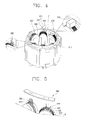
- Figure 3 is a perspective view showing a switched reluctance mtor in accordance with the present invention;
- Figure 4 is a perspective view showing an assembly constituting the switched reluctance motor in accordance with the present invention;
- Figure 5 is an exploded perspective view showing a sensor and a sensor substrate constituting the switched reluctance motor in accordance with the present invention;
- Figure 6 is an exploded perspective view showing a parking magnet and a retainer constituting the switched reluctance motor in accordance with the present invention; and
- Figure 7 is a perspective view showing a stator constituting the switched reluctance motor in accordance with the present invention.
- Reference will now be made in detail to the preferred embodiments of the present invention, examples of which are illustrated in the accompanying drawings.
- Figure 3 is a perspective view showing one embodiment of a switched reluctance motor in accordance with the present invention. The same reference numbers are given to the same parts as those of the conventional art.
- As shown, the switched reluctance motor includes: a
stator 500 including acylindrical body 510, a plurality of salient poles (P) coupled to an inner circumferential surface of thecylindrical body 510 and provided with awinding coil 520, and anexterior member 530 having a cylindrical shape by encompassing an assembly made by the coupling of thecylindrical body 510, the salient poles (P) and the like; arotor 200 rotatably inserted in theexternal member 530 of thestator 500; arotary shaft 300 coupled to therotor 200; and aphase indication magnet 230 coupled to therotor 200 or therotary shaft 300. - As the conventional art, the
rotor 200 is made as alamination body 210 formed in such a manner that a plurality of thin plates are laminated one on top of another, and a plurality of protrudingpole portions 220, each having a certain width and height are formed at an outer circumferential surface of thelamination body 210 in a longitudinal direction. The protrudingpole portions 220 are formed at regular intervals in a circumferential direction of thelamination body 210. - And the
rotary shaft 300 is penetratingly coupled at the middle of therotor 200, and thephase indication magnet 230 is fixedly coupled to therotary shaft 300. Thephase indication magnet 230 is formed as a disc shape having a certain thickness, and poles are magnetized at the disc in a circumferential direction, wherein the number of poles corresponds to the number of salient poles (P) of therotor 200. - As shown in Figure 4, the
cylindrical body 510 of thestator 500 has predetermined width, outer diameter and length, and a plurality ofcoupling grooves 511 are formed at an inner circumferential surface of thecylindrical body 510 at regular intervals. Thecoupling grooves 511 are formed in a longitudinal direction. Thecylindrical body 510 may be formed as a lamination body formed by lamination of a plurality of thin plates. - As for the salient pole (P),
insulation materials 550, each having a predetermined area are respectively formed at both sides of atooth 540 having a predetermined shape, and a windingcoil 520 wound around thetooth 540 is positioned between theinsulation materials 550. The salient poles (P) are insertedly fixed to thecoupling grooves 511 formed at an inner circumferential surface of thecylindrical body 510 of thestator 500 at regular intervals in a circumferential direction, respectively. -
Hall sensors 560 for sensing a phase of thephase indication magnet 230 are mounted at one or two (P) of the plurality of salient poles (P) coupled to thecylindrical body 510. And aparking magnet 570 is mounted at a salient pole (P) facing the salient pole (P) provided with thehall sensor 560, wherein theparking magnet 570 holds a position of therotor 200 when therotor 200 is stopped, so that therotor 200 is positioned at an effective torque generation area of thestator 500 when being initially activated. As shown in Figure 5, thehall sensors 560 are connected to thesensor substrate 580 having a predetermined shape. Preferably, thesensor substrate 580 is formed with both sides curved. -
Insertion grooves 551 having a predetermined shape are formed at an upper surface of theinsulation material 550 constituting the salient pole (P), and thehall sensors 560 are inserted in theinsertion grooves 551, respectively. - The
parking magnet 570 is formed as a hexahedron, and is mounted by being adhered to the salient pole (P) with a molding material. Theparking magnet 570 may be adhered thereto by an adhesive besides the molding material. - Figure 6 shows a modified example of mounting the
parking magnet 570 to the salient pole (P). As shown, theparking magnet 570 is inserted in a predetermined-shapedretainer 590, and theretainer 590 is coupled to the salient pole (P). Theretainer 590 includes abox portion 591 formed as a quadrangular box shape with its one side opened; and acoupling protruding portion 592 protrudingly formed at a lower surface of thebox portion 591 as a predetermined shape. Thecoupling protruding portion 592 of theretainer 590 is inserted in aninsertion groove 552 formed at the salient pole (P). - As shown in Figure 7, the
exterior member 530 is formed as a cylindrical shape, so as to encompass thecylindrical body 510, the salient poles (P) to be coupled to thecylindrical body 510, thehall sensor 560 mounted to the salient pole (P), thesensor substrate 580 and theparking magnet 570 shown in Figure 4. - Preferably, the
exterior member 530 is made of a molding material, and the molding material is a thermosetting resin. Theexterior member 530 is formed by positioning an assembly including thecylindrical body 510, the salient poles (P), thehall sensor 560, thesensor substrate 580 and theparking magnet 570 in a mold having a predetermined shape, then injecting a melted molding material into the mold and solidifying the molding material. - The
exterior member 530 includes acylindrical body portion 531 formed by encompassing thecylindrical body 510 and the salient poles (P) so that thecylindrical body 510 and the salient poles (P) are positioned inside theexterior member 530; asensor cover portion 532 protrudingly formed at one side of thecylindrical body portion 531 and covering thehall sensors 560 and thesensor substrate 580; and a stoppingcover portion 533 protrudingly formed at one side of thecylindrical body portion 531 and covering theparking magnet 570. - The
sensor cover portion 532 and the stoppingcover portion 533 are positioned to face each other. - The
hall sensor 560 and thesensor substrate 580 may be positioned at a variety of positions, and also theparking magnet 570 may be positioned at a variety of positions. - Also, two or
more hall sensors 560 may be mounted. - In addition, as another embodiment of the
exterior member 530, the shape of theexterior member 530 may be variously implemented. - The operation and effect of the above-described switched reluctance motor will now be described.
- First, when power is supplied to the motor and a current flows through the winding
coils 520, reluctance torque is generated between thestator 500 and therotor 200, thereby rotating therotor 200. As therotor 200 rotates, therotary shaft 300 coupled to therotor 200 and thephase indication magnet 230 coupled to therotary shaft 300 are rotated together. - And as the
phase indication magnet 230 is rotated, thehall sensor 560 senses a phase of thephase indication magnet 230, and controls a current supplied to the windingcoil 520 based on the sensed phase, thereby varying a speed of therotor 200. - In case of stopping the
rotor 200, by the interaction between thephase indication magnet 230 connected to therotor 200 and theparking magnet 570, therotor 200 is stopped at an effective torque generation area. - The switched reluctance motor is in a state that the
exterior member 530 encompasses thecylindrical body 510, the salient poles (P) provided with the windingcoil 520, theparking magnet 570, thehall sensors 560, thesensor substrate 580 and the like. Therefore, when the motor is applied to a household appliance such as a cleaner or the like, foreign substances introduced from the outside are prevented from coming in contact with or being accumulated on the windingcoil 520, thehall sensor 560, thesensor substrate 580 or the like. - Also, the
exterior member 530 is formed by molding after thecylindrical body 510, the salient poles (P), theparking magnet 570, thehall sensor 560, thesensor substrate 580 and the like are assembled. For this reason, an exterior structure is relatively simple, the number of components is decreased, and the number of assembling processes are decreased. - In the conventional structure, the
holder 400 is manufactured, thehall sensor 150, thesensor substrate 170, theparking magnet 160 and the like are mounted to theholder 400, and then theholder 400 is mounted to acylindrical body 110. For this reason, the number of components and the number of assembling processes are relatively great, and assembling operation is complicated because theholder 400 and thecylindrical body 110 should be coupled together, precisely maintaining an assembly tolerance. - In contrast, in the present invention, because the exterior member is manufactured by molding after the
cylindrical body 510, the salient poles (P), theparking magnet 570, thehall sensor 560 and thesensor substrate 580 are assembled, manufacturing is simple, and operation for maintaining an assembly tolerance of a relative component is excluded, thereby simplifying the assembling operation. - As so far described, the switched reluctance motor in accordance with the present invention has a simple exterior structure, and is manufactured with a small number of components through a remarkably decreased number of assembling processes, thereby being proper to be mass produced. Also, assembling productivity can be improved, and a manufacturing cost is reduced, thereby improving competitiveness of a product.
- In addition, when the switched reluctance motor in accordance with the present invention is applied to household appliances such as a cleaner and the like, fine foreign substances are prevented from colliding with a winding coil and being oxidized, so that a life span of a component is extended thus to improve reliability.
- As the present invention may be embodied in several forms without departing from the spirit or essential characteristics thereof, it should also be understood that the above-described embodiments are not limited by any of the details of the foregoing description, unless otherwise specified, but rather should be construed broadly within its spirit and scope as defined in the appended claims, and therefore all changes and modifications that fall within the metes and bounds of the claims, or equivalence of such metes and bounds are therefore intended to be embraced by the appended claims.
Claims (14)
- A switched reluctance motor comprising:a stator including a cylindrical body, a plurality of salient poles coupled to an inner circumferential surface of the cylindrical body and provided with a winding coil, and an exterior member formed as a cylindrical shape by encompassing an assembly formed by coupling of the cylindrical body, the salient poles and the like;a rotor rotatably inserted inside the exterior member of the stator;a rotary shaft coupled to the rotor; anda phase indication magnet coupled to the rotor or the rotary shaft.
- The motor of claim 1, wherein the exterior member is formed by molding a molding material.
- The motor of claim 1, wherein a sensor cover portion for covering a sensor for sensing a phase of the phase indication magnet and a sensor substrate is protrudingly formed at one side of the exterior member as a predetermined shape.
- The motor of claim 3, wherein the sensor cover portion is positioned to face the phase indication magnet.
- The motor of claim 3, wherein the sensor is mounted at the salient pole.
- The motor of claim 3, wherein the sensor is fixed by being inserted in an insertion groove formed at the salient pole.
- The motor of claim 3, wherein the sensor is a plurality of hall sensors.
- The motor of claim 1, wherein a stopping cover portion for covering a parking magnet stopping and positioning the rotor at an effective torque generation area together with the phase indication magnet is protrudingly formed at one side of the exterior member.
- The motor of claim 8, wherein the stopping cover portion is positioned to face the phase indication magnet.
- The motor of claim 8, wherein the parking magnet is mounted at the salient pole.
- The motor of claim 10, wherein the parking magnet is adhered to the salient pole by a molding material.
- The motor of claim 10, wherein the parking magnet is adhered to the salient pole by an adhesive.
- The motor of claim 10, wherein the parking magnet is inserted in a retainer having a predetermined shape, and the retainer is coupled to the salient pole.
- The motor of claim 13, wherein the retainer comprises:a box portion formed as a quadrangular box shape whose one side is opened; anda coupling protruding portion protrudingly formed at a lower surface of the box portion as a predetermined shape,wherein the coupling protruding portion is inserted in an insertion groove formed at the salient pole.
Applications Claiming Priority (1)
| Application Number | Priority Date | Filing Date | Title |
|---|---|---|---|
| KR1020040058736A KR100568788B1 (en) | 2004-07-27 | 2004-07-27 | Switched reluctance motor |
Publications (2)
| Publication Number | Publication Date |
|---|---|
| EP1622246A2 true EP1622246A2 (en) | 2006-02-01 |
| EP1622246A3 EP1622246A3 (en) | 2006-12-27 |
Family
ID=34939016
Family Applications (1)
| Application Number | Title | Priority Date | Filing Date |
|---|---|---|---|
| EP05102166A Withdrawn EP1622246A3 (en) | 2004-07-27 | 2005-03-18 | Switched reluctance motor |
Country Status (3)
| Country | Link |
|---|---|
| US (1) | US7459812B2 (en) |
| EP (1) | EP1622246A3 (en) |
| KR (1) | KR100568788B1 (en) |
Cited By (1)
| Publication number | Priority date | Publication date | Assignee | Title |
|---|---|---|---|---|
| WO2014044496A3 (en) * | 2012-09-19 | 2014-07-24 | Asml Netherlands B.V. | Method of calibrating a reluctance actuator assembly, reluctance actuator and lithographic apparatus comprising such reluctance actuator |
Families Citing this family (2)
| Publication number | Priority date | Publication date | Assignee | Title |
|---|---|---|---|---|
| JP6071275B2 (en) * | 2012-06-29 | 2017-02-01 | 株式会社東芝 | Permanent magnet motor and method of manufacturing permanent magnet motor |
| KR101363227B1 (en) * | 2012-09-17 | 2014-02-14 | 뉴모텍(주) | Motor with hall sensor cover and waterproof cover |
Family Cites Families (16)
| Publication number | Priority date | Publication date | Assignee | Title |
|---|---|---|---|---|
| GB1427417A (en) * | 1973-10-04 | 1976-03-10 | Westool Ltd | Electric motor |
| US4015154A (en) * | 1974-12-23 | 1977-03-29 | Sony Corporation | Motor and method for making same |
| US3984711A (en) * | 1975-04-07 | 1976-10-05 | Warner Electric Brake & Clutch Company | Variable reluctance step motor with permanent magnets |
| US4935080A (en) * | 1988-01-29 | 1990-06-19 | Kollmorgen Corporation | Protection and bonding of neodymium-boron-iron magnets used in the formation of magnet assemblies |
| JPH0389899A (en) * | 1989-09-01 | 1991-04-15 | Hitachi Ltd | Stepping motor and recording method of rotor-position signal in same stepping motor |
| US5148070A (en) * | 1991-08-30 | 1992-09-15 | Platt Saco Lowell Corporation | Apparatus for commutation of an electric motor |
| DE19527981A1 (en) * | 1995-07-31 | 1997-02-06 | Aeg Kleinmotoren Gmbh | Electronically commutated electric motor, such as switched reluctance (SR) drive motor for motor vehicles, washing machines, lawn mowers etc - has magnetic field sensitive element for each phase of motor arranged at small distance from pole wheels |
| DE19622186A1 (en) * | 1996-06-03 | 1997-12-04 | Hilti Ag | Electric motor |
| US20040091966A1 (en) * | 1999-08-30 | 2004-05-13 | Martin Zeidler | Polypeptide regulation by conditional inteins |
| KR100319139B1 (en) * | 2000-02-10 | 2002-01-04 | 구자홍 | Parking device for single phase Switched Reluctance Motor |
| JP2001238377A (en) * | 2000-02-24 | 2001-08-31 | Minebea Co Ltd | Rotating electric machine |
| DE10057255A1 (en) * | 2000-11-18 | 2002-05-23 | Bosch Gmbh Robert | Electrical machine with composite stator with windings has pole shoes with aligned arms in stator peripheral direction, each pointing towards adjacent pole, acting as magnetic flux guide body |
| US6462443B2 (en) * | 2001-01-18 | 2002-10-08 | Sunonwealth Electric Machine Industry Co., Ltd. | Brushless D.C. motors structure |
| US6552459B2 (en) * | 2001-03-20 | 2003-04-22 | Emerson Electric Co. | Permanent magnet rotor design |
| KR100437058B1 (en) * | 2002-10-01 | 2004-06-23 | 엘지전자 주식회사 | Single phase motor |
| US7451543B2 (en) * | 2004-10-04 | 2008-11-18 | Emerson Electric Co. | Methods of securing a bearing with an adaptor sleeve within an opening of a housing |
-
2004
- 2004-07-27 KR KR1020040058736A patent/KR100568788B1/en not_active Expired - Fee Related
-
2005
- 2005-03-18 EP EP05102166A patent/EP1622246A3/en not_active Withdrawn
- 2005-03-30 US US11/093,308 patent/US7459812B2/en not_active Expired - Fee Related
Cited By (2)
| Publication number | Priority date | Publication date | Assignee | Title |
|---|---|---|---|---|
| WO2014044496A3 (en) * | 2012-09-19 | 2014-07-24 | Asml Netherlands B.V. | Method of calibrating a reluctance actuator assembly, reluctance actuator and lithographic apparatus comprising such reluctance actuator |
| US10372045B2 (en) | 2012-09-19 | 2019-08-06 | Asml Netherlands B.V. | Method of calibrating a reluctance actuator assembly, reluctance actuator and lithographic apparatus comprising such reluctance actuator |
Also Published As
| Publication number | Publication date |
|---|---|
| US7459812B2 (en) | 2008-12-02 |
| KR100568788B1 (en) | 2006-04-07 |
| US20060022542A1 (en) | 2006-02-02 |
| EP1622246A3 (en) | 2006-12-27 |
| KR20060010140A (en) | 2006-02-02 |
Similar Documents
| Publication | Publication Date | Title |
|---|---|---|
| TWI236202B (en) | Rotor of motor | |
| CN110291700B (en) | Stator and motor comprising same | |
| US5465019A (en) | High-efficiency, low-noise electronically commutated motor having improved starting capability | |
| EP1870990A2 (en) | Axial air-gap type motor | |
| US7362024B2 (en) | Rotor of BLDC motor | |
| WO2004001930A1 (en) | Rotor for external rotor-type permanent magnet motor | |
| JP2010246171A (en) | Axial gap type rotating electrical machine | |
| CN103516063B (en) | Motor assembling structure | |
| WO2002087059A1 (en) | Stator for reciprocating motor | |
| KR20190057643A (en) | Motor | |
| JP2021535715A (en) | motor | |
| JP2018110487A (en) | Rotor and electric motor | |
| JP2001218409A (en) | Stator of motor | |
| US7459812B2 (en) | Switched reluctance motor | |
| JP2004222356A (en) | Rotating electric equipment | |
| JP2019187132A (en) | Motor and brushless wiper motor | |
| EP1835601B1 (en) | Hybrid induction motor | |
| KR20160010820A (en) | Direct current motor without contacting power supplier | |
| EP4033642B1 (en) | Rotor magnet retainer | |
| EP4358366A1 (en) | Stator unit, molded motor, and method of manufacturing stator unit | |
| KR20180089173A (en) | Motor | |
| KR101055129B1 (en) | Motor and clothing treatment device having same | |
| JP5034072B2 (en) | Radial gap type DC brushless motor and manufacturing method thereof | |
| CN115208150A (en) | Permanent magnet ferromagnetic field type brush DC motor and its manufacturing method | |
| KR20220059356A (en) | Stator structure for small size motor module |
Legal Events
| Date | Code | Title | Description |
|---|---|---|---|
| PUAI | Public reference made under article 153(3) epc to a published international application that has entered the european phase |
Free format text: ORIGINAL CODE: 0009012 |
|
| 17P | Request for examination filed |
Effective date: 20050318 |
|
| AK | Designated contracting states |
Kind code of ref document: A2 Designated state(s): AT BE BG CH CY CZ DE DK EE ES FI FR GB GR HU IE IS IT LI LT LU MC NL PL PT RO SE SI SK TR |
|
| AX | Request for extension of the european patent |
Extension state: AL BA HR LV MK YU |
|
| PUAL | Search report despatched |
Free format text: ORIGINAL CODE: 0009013 |
|
| AK | Designated contracting states |
Kind code of ref document: A3 Designated state(s): AT BE BG CH CY CZ DE DK EE ES FI FR GB GR HU IE IS IT LI LT LU MC NL PL PT RO SE SI SK TR |
|
| AX | Request for extension of the european patent |
Extension state: AL BA HR LV MK YU |
|
| RIC1 | Information provided on ipc code assigned before grant |
Ipc: H02K 37/04 20060101AFI20050525BHEP Ipc: H02K 29/08 20060101ALI20061117BHEP Ipc: H02K 1/14 20060101ALI20061117BHEP |
|
| 17Q | First examination report despatched |
Effective date: 20070313 |
|
| AKX | Designation fees paid |
Designated state(s): DE FR GB |
|
| GRAP | Despatch of communication of intention to grant a patent |
Free format text: ORIGINAL CODE: EPIDOSNIGR1 |
|
| INTG | Intention to grant announced |
Effective date: 20160331 |
|
| STAA | Information on the status of an ep patent application or granted ep patent |
Free format text: STATUS: THE APPLICATION IS DEEMED TO BE WITHDRAWN |
|
| 18D | Application deemed to be withdrawn |
Effective date: 20160811 |