EP1622172A1 - Wire harness manufacturing method and wire harness - Google Patents
Wire harness manufacturing method and wire harness Download PDFInfo
- Publication number
- EP1622172A1 EP1622172A1 EP04729741A EP04729741A EP1622172A1 EP 1622172 A1 EP1622172 A1 EP 1622172A1 EP 04729741 A EP04729741 A EP 04729741A EP 04729741 A EP04729741 A EP 04729741A EP 1622172 A1 EP1622172 A1 EP 1622172A1
- Authority
- EP
- European Patent Office
- Prior art keywords
- wires
- wire
- proximal end
- wire harness
- terminal
- Prior art date
- Legal status (The legal status is an assumption and is not a legal conclusion. Google has not performed a legal analysis and makes no representation as to the accuracy of the status listed.)
- Withdrawn
Links
Images



Classifications
-
- H—ELECTRICITY
- H01—ELECTRIC ELEMENTS
- H01B—CABLES; CONDUCTORS; INSULATORS; SELECTION OF MATERIALS FOR THEIR CONDUCTIVE, INSULATING OR DIELECTRIC PROPERTIES
- H01B13/00—Apparatus or processes specially adapted for manufacturing conductors or cables
- H01B13/012—Apparatus or processes specially adapted for manufacturing conductors or cables for manufacturing wire harnesses
- H01B13/01218—Apparatus or processes specially adapted for manufacturing conductors or cables for manufacturing wire harnesses the wires being disposed by hand
- H01B13/01227—Apparatus or processes specially adapted for manufacturing conductors or cables for manufacturing wire harnesses the wires being disposed by hand using a layout board
-
- H—ELECTRICITY
- H01—ELECTRIC ELEMENTS
- H01B—CABLES; CONDUCTORS; INSULATORS; SELECTION OF MATERIALS FOR THEIR CONDUCTIVE, INSULATING OR DIELECTRIC PROPERTIES
- H01B13/00—Apparatus or processes specially adapted for manufacturing conductors or cables
- H01B13/012—Apparatus or processes specially adapted for manufacturing conductors or cables for manufacturing wire harnesses
-
- H—ELECTRICITY
- H01—ELECTRIC ELEMENTS
- H01B—CABLES; CONDUCTORS; INSULATORS; SELECTION OF MATERIALS FOR THEIR CONDUCTIVE, INSULATING OR DIELECTRIC PROPERTIES
- H01B7/00—Insulated conductors or cables characterised by their form
- H01B7/36—Insulated conductors or cables characterised by their form with distinguishing or length marks
- H01B7/365—Insulated conductors or cables characterised by their form with distinguishing or length marks being indicia imposed on the insulation or conductor
-
- H—ELECTRICITY
- H01—ELECTRIC ELEMENTS
- H01B—CABLES; CONDUCTORS; INSULATORS; SELECTION OF MATERIALS FOR THEIR CONDUCTIVE, INSULATING OR DIELECTRIC PROPERTIES
- H01B7/00—Insulated conductors or cables characterised by their form
- H01B7/36—Insulated conductors or cables characterised by their form with distinguishing or length marks
- H01B7/361—Insulated conductors or cables characterised by their form with distinguishing or length marks being the colour of the insulation or conductor
Definitions
- This invention relates to a method of producing a wire harness and also to a wire harness.
- fork-like support members 102 for holding wires 101 in a predetermined shape are mounted on an installation board 100 as shown in Fig. 6. Therefore, the wires 11 are installed in such a manner that these wires are supported by the support members 102, thereby forming a wire harness 110 of a predetermined shape.
- the wire length becomes insufficient, or becomes too large and loose when the earth wire 101a is installed in a wrong direction, which invites a problem that the desired wire harness 110 can not be obtained.
- the classification of the earth wires 101a by color invites an increased cost.
- This invention has been made in view of the above problems, and an object of the invention is to provide a wire harness producing method as well as a wire harness, in which wires which have the same basic appearance, and are to be installed to extend in a plurality of directions from a common proximal end terminal can be installed in the proper directions, respectively.
- each wire is installed according to the installation marking provided on the proximal end terminal-adjacent portion thereof, and therefore can be prevented from being installed in a wrong direction.
- the wire harness of the above Paragraph (5) when the open distal end of any of the plurality of wires extending from each proximal end terminal is to be connected to any of the plurality of connection terminals, the wire is connected to the connection terminal according to the wire-indicating marking (provided on at least one of the installation board and the connection terminal) corresponding to the identification marking provided on that portion of the wire disposed adjacent to the open distal end thereof. Therefore, a connection error can be prevented.
- 10A to 10D denote wire harnesses
- 11 and 12 denote wires
- 13 denotes a installation board
- 14 denotes an open distal end
- 20 denotes a bonder (proximal end terminal)
- 21 denotes an installation marking
- 30 denotes a connector (connection terminal)
- 31 denotes a proximal end terminal-indicating marking.
- FIG. 1 is an explanatory view showing the first embodiment of the wire harness producing method of the present invention.
- a plurality of bonders 20a, 20b, serving as proximal end terminals, are mounted on an installation board 13.
- Installation markings 21 are provided respectively on those portions of a plurality of wires 11a, 11b, 11c, 11d, 11e (extending from the first bonder 20a) disposed adjacent to their proximal ends, the installation markings 21 indicating whether these wires are to be installed to the right or the left from the bonder 20a.
- Installation markings 21 are provided respectively on those portions of a plurality of wires 12a, 12b, 12c (extending from the second bonder 20b) disposed adjacent to their proximal ends, the installation markings 21 indicating whether these wires are to be installed to the right or the left from the bonder 20a.
- those wires to be installed to the left from the bonders 20a, 20b can bear a mark 21a of a circle as shown in Fig. 2(A), while those wires to be installed to the right from the bonders 20a, 20b can bear a mark 21b of X as shown in Fig. 2(B).
- the circle mark 21a is provided on that portion of each of the wires 11a, 11b (to be installed to the left) disposed adjacent to the proximal end terminal.
- the X mark 21b is provided on that portion of each of the wires 11c, 11d, 11e (to be installed to the right) disposed adjacent to the proximal end terminal.
- Connectors 30a, 30b serving as connection terminals, are provided respectively in predetermined positions on the installation board 13, and open distal ends 14 (see Fig. 2(A) and 2(B)) of the wires 11, each having a terminal connected thereto, are connected to the connectors 30a, 30b (These terminals are not shown).
- Proximal end terminal-indicating markings 31a, 31b are provided on the installation board 13, and are disposed near to the connectors 30a, 30b, respectively, each of the proximal end terminal-indicating markings 31a, 31b indicating which section of the connector 30a, 30b the open distal end 14 of each wire 11 should be connected to.
- Square sections corresponding respectively to terminals of the connector 30a, are provided at the proximal end terminal-indicating marking 31a provided near to the connector 30a in Fig. 1, and the square sections indicate those wires 11 (extending respectively from the bonders 20) which should be connected to this connector.
- the wire harness producing method of the present invention will be described.
- the first bonder 20a and the second bonder 20b are mounted on the installation board 13 in such a manner that the two bonders are spaced a predetermined distance from each other.
- the connectors 30a, 30b are mounted in the predetermined positions, respectively, and the proximal end terminal-indicating markings 31 are provided near to the connectors 30a, 30b, respectively.
- the wires 11a, 11b, each bearing the circle mark 21a at its proximal end terminal-adjacent portion are installed in the left direction.
- the wires 11c, 11d, 11e, each bearing the X mark 21b at its proximal end terminal-adjacent portion are installed in the right direction.
- fork-like support members are provided at suitable intervals, and therefore the wires 11 are supported by the support members.
- the wire 11e installed to extend to the right from the first bonder 20a, is connected to the connector 30a. At this time, the wire 11e is connected to the terminal of the connector 30a which corresponds to the section of the proximal end terminal-indicating marking 31 a bearing the mark (1) indicative of the first bonder 20a.
- the wires 12a and 12b are installed in the left direction, and the wire 12a is connected to the connector 30a.
- This wire is connected to the terminal which corresponds to the section of the proximal end terminal-indicating marking 31a bearing the mark (2) indicative of the second bonder 20b.
- each wire 11 when installing the plurality of wires 11 (which have the same basic appearance, and extend from the same bonder 20) in their respective predetermined directions, each wire 11 is installed in its predetermined direction according to the installation marking 20 (the circle mark 21a or the X mark 21b) provided on its proximal end terminal-adjacent portion, and therefore each wire can be prevented from being installed in a wrong direction.
- the installation marking 20 the circle mark 21a or the X mark 21b
- each of the open distal ends 14 of the plurality of wires 11, 12, extending from the bonders 20a, 20b, to either of the plurality of connectors 30a, 30b each of the open distal ends is connected to the corresponding terminal of the connector 30a, 30b in accordance with the proximal end terminal-indicating marking 31a, 31b provided on the installation board 13, and therefore a connection error can be prevented.
- FIG. 3 shows a wire harness producing method and a wire harness according to the second embodiment of the present invention.
- installation markings 21, for example as shown in Fig. 2, are provided respectively on those portions of a plurality of wires 11a, 11b, 11c, 11d (extending from a bonder 20 serving as a proximal end terminal) disposed adjacent to the proximal end terminal, the installation markings 21 indicating whether the wires are to be installed to the right or the left from the bonder 20.
- a circle mark 21a is provided on the proximal end terminal-adjacent portion of each of the wires 11a, 11b to be installed to the left from the bonder 20, while an X mark 21b is provided on the proximal end terminal-adjacent portion of each of the wires 11c, 11d to be installed to the right from the bonder 20.
- an identification marking 32 for identifying the wire 11 is provided on that portion of each wire 11 disposed adjacent to its open distal end 14.
- a pattern of horizontal-line hatching 32b indicative of the wire 11c is provided on the wire 11c.
- a pattern of oblique-line hatching 32a indicative of the wire 11d is provided on the wire 11d.
- the identification marking can be provided in a belt-like manner around the entire periphery as is the case with the identification marking 32a, or it can be provided in a predetermined shape as is the case with the identification marking 32b.
- the identification marking can be provided by printing or by winding a tape-like member on the wire.
- connectors 30a, 30b serving as connection terminals, are provided respectively in predetermined positions on an installation board 13, and the open distal ends 14 of the wires 11c, 11d are connected to the connectors 30a, 30b, respectively.
- the connectors 30a, 30b are provided on the installation board 13.
- Wire-indicating markings 33a, 33b are disposed near to the connectors 30a, 30b, respectively, each of the wire-indicating markings 33a, 33b indicating which terminal of the connector 30a, 30b the open distal end 14 of each wire 11d, 11c should be connected to.
- Square sections corresponding respectively to the terminals of the connector 30a, are provided at the wire-indicating marking 33a provided near to the connector 30a in Fig. 3, and this wire-indicating marking indicates a square section to which the wire 11d should be connected.
- a mark 34a having the same pattern as that of the identification marking 32a provided on the wire 11d, is provided on the square section corresponding to the terminal to which the wire 11d is to be connected.
- the mark 34a having the same horizontal-line hatching pattern as the oblique-line hatching pattern of the identification marking 32, is provided on the square section corresponding to the terminal of the connector 30a to which the wire 11d (having the identification marking 32 of the oblique line-hatching pattern) is to be connected.
- a mark 34b having a horizontal-line hatching pattern, is provided on the square section corresponding to the terminal of the connector 30b to which the wire 11c (having the identification marking 32b of the horizontal line-hatching pattern) is to be connected.
- the bonder 20 is provided on the installation board 13, and the connectors 30a, 30b are provided in the predetermined positions, respectively.
- the wire-indicating markings 33a, 33b are provided near to the connectors 30a, 30b, respectively.
- the wires 11a, 11b, each bearing the circle mark 21a at its proximal end terminal-adjacent portion are installed in the left direction.
- the wires 11c, 11d, each bearing the X mark 21b at its proximal end terminal-adjacent portion are installed in the right direction, and are supported by support members.
- Each of the wires 11c, 11d, installed to the right from the bonder 20, is connected to either of the connectors 30a, 30b.
- the wire 11c is connected to the terminal corresponding to the section of the wire-indicating marking 33b bearing the mark 34b of the horizontal-line hatching pattern since the identification marking 32b of the horizontal-line hatching pattern is provided on the wire 11c.
- the wire 11d having the identification marking 32 of the oblique-line hatching pattern, is connected to the terminal corresponding to the section of the wire-indicating marking 33a bearing the mark 34a of the oblique-line hatching pattern.
- each of the open distal ends 14 of the plurality of wires 11, extending from the bonder 20, to either of the plurality of connectors 30a, 30b each of the open distal ends is connected in accordance with the wire-indicating marking 33 (provided on the installation board 13) corresponding to the identification marking 32 provided on that portion of the wire 11 disposed adjacent to the open distal end 14 thereof. Therefore, a connection error can be prevented.
- FIG. 4 shows a wire harness producing method and a wire harness which are provided in accordance with the third embodiment of the present invention.
- a plurality of bonders 20a, 20b, serving as proximal end terminals are mounted on an installation board 13 in such a manner that these bonders are spaced a predetermined distance from each other.
- Installation markings 21 are provided respectively on those portions of a plurality of wires 11a, 11b, 11c, 11d, 11e (extending from the first bonder 20a) disposed adjacent to the proximal end terminal.
- installation markings 21 are provided respectively on those portions of a plurality of wires 12a, 12b, 12c (extending from the second bonder 20b) disposed adjacent to the proximal end terminal.
- Connectors 30a, 30b, 30c, serving as connection terminals, are provided respectively in predetermined positions on the installation board 13, and open distal ends 14 of the wires 11e, 11d, 11c, 12a are connected to the connectors 30a, 30b, 30c.
- Indication markings 35a, 35b, 35c are provided on the installation board 13, and are disposed near to the connectors 30a, 30b, 30c, respectively, each of these indication markings indicating which section of the connector 30 the open distal end 14 of each wire 11, 12 should be connected to.
- the indication markings 35a, 35b, 35c serve as the above-mentioned proximal end terminal-indicating markings 31 and also as the above-mentioned wire-indicating markings 33.
- each mark 36 bears a numeral which indicates the wire 11a, 11b, 11c, extending from the first bonder 20a, or the wire 12a extending from the second bonder 20b.
- the terminal position to which the wire is to be connected, the wire 11 to be connected, and the bonder 20 at the proximal end of this wire 11 can all be known from the indication marking 35.
- the first bonder 20a and the second bonder 20b are mounted on the installation board 13 in such a manner that the two bonders are spaced a predetermined distance from each other.
- the connectors 30a, 30b, 30c are provided in the predetermined positions, respectively, and the indication markings 35a, 35b, 35c are provided near to the connectors 30a, 30b, 30c, respectively.
- the wires 11a, 11b, each bearing a circle mark 21 a at its proximal end terminal-adjacent portion are installed in the left direction.
- the wires 11c, 11d, 11e, each bearing an X mark 21b at its proximal end terminal-adjacent portion are installed in the right direction, and are supported by support members.
- Each of the wires 11c, 11d, 11e, installed to the right from the first bonder 20a, is connected to any of the connectors 30a, 30b, 30c. At this time, each wire 11 is installed and connected in such a manner that the identification marking 32, provided on this wire 11, coincides with the pattern, numeral, etc., provided at the indication marking 35.
- the wires 12a, 12b, each bearing a circle mark 21a at its proximal end terminal-adjacent portion, are installed in the left direction, and the wire 12a is connected to the connector 30c.
- each wire 11 is installed in the predetermined direction according to the installation marking 21 provided at the proximal end terminal-adjacent portion of the wire 11, and therefore each wire can be prevented from being installed in a wrong direction.
- Figs. 5(a) and 5(b) show a wire harness producing method and a wire harness according to a fourth embodiment of the present invention.
- a connector 42 serving as a proximal end terminal, is provided at a car stereo sound system body 40, and four (front/rear and left/right) speakers 41a, 41b, 41c, 41d are provided as connection terminals.
- installation markings 21 are provided respectively on those portions of wires 11 disposed adjacent to the proximal end terminal, as shown in Fig. 5(B).
- a circle mark 21a serving as the installation marking 21, is provided on each of the wires 11a, 11b which are to be installed to the left from the car stereo sound system body 40, while for example, an X mark 21b, serving as the installation marking 21, is provided on each of the wires 11c, 11d which are to be installed to the right.
- An indication marking 37a of right-upper oblique-line hatching indicative of the front-side speaker is provided on that portion of each of the wires 11b, 11c disposed adjacent to an open distal end thereof.
- Wire-indicating markings 33a, 33b of similar right-upper oblique-line hatching are provided respectively on connectors 30a, 30b of the front-side speakers 41a, 41b.
- an indication marking 37b of left-upper oblique-line hatching indicative of the rear-side speaker is provided on that portion of each of the wires 11a, 11d disposed adjacent to an open distal end thereof.
- Wire-indicating markings 33c, 33d of similar left-upper oblique-line hatching are provided respectively on connectors 30c, 30d of the rear-side speakers 41c, 41d.
- the wires 11 extending from the connector 42 of the car stereo sound system body 40 are installed to the left, while the wires 11c, 11d, each bearing the X mark 21b, are installed to the right.
- Each of the wires 11 is connected to the speaker 30 having the same marking as the identification marking 37 provided at that portion of this wire 11 disposed adjacent to the open distal end thereof.
- the wires 11 are installed in their respective predetermined directions in accordance with the installation markings 21 provided respectively on the proximal end terminal-adjacent portions thereof, and therefore each wire can be prevented from being installed in a wrong direction.
- wire harness producing methods and wire harnesses of the present invention are not limited to the above embodiments, and suitable modifications, improvements and so on can be made.
- the proximal end terminal-indicating markings 31, the wire-indicating markings 33 and the indication markings 35 are provided on the installation board 13, these markings can be provided on the connectors 30. As another alternative, these markings can be provided on both of the installation board 13 and the connectors 30.
- the invention can be similarly applied to the case where the wires are directed in many directions, In this case, with respect to the installation markings 21, there are provided installation markings 21 of different kinds corresponding in number to the installation directions.
- the circle marks 21a and the X marks 21b used as the installation markings 21, the horizontal-line hatching 34b and the oblique-line hatching 34a used as the wire-indicating markings 33, etc., are shown merely as examples, and the markings are not limited to these.
- each wire is installed according to the installation marking provided on the proximal end terminal-adjacent portion thereof, and therefore can be prevented from being installed in a wrong direction.
- wire harness producing methods and the wire harnesses of the present invention are useful not only as wire harnesses used in a vehicle such as an automobile but also as wire harnesses used in various apparatuses.
Landscapes
- Engineering & Computer Science (AREA)
- Manufacturing & Machinery (AREA)
- Manufacturing Of Electrical Connectors (AREA)
- Insulated Conductors (AREA)
- Connections Arranged To Contact A Plurality Of Conductors (AREA)
Abstract
Description
- This invention relates to a method of producing a wire harness and also to a wire harness.
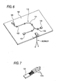
- In a conventional wire harness producing method, fork-
like support members 102 forholding wires 101 in a predetermined shape are mounted on aninstallation board 100 as shown in Fig. 6. Therefore, thewires 11 are installed in such a manner that these wires are supported by thesupport members 102, thereby forming awire harness 110 of a predetermined shape. - There is disclosed a technique in which at this time, those wires to be inserted later into the
same connector 103 are bundled together by a colored tape, a colored rubber band or the like so that the connectors to which the wires are to be inserted later can be distinguished from one another, thereby preventing a mistake (see, for example, JP-A-11-25781 (Page 3, Fig. 1)). - Incidentally, there are cases where there are provided a plurality of earth wires for connection to a car body of an automobile to obtain body earthing. In such a case, ordinary wires, having the same appearance, are used as the
earth wires 101a as shown in Fig. 7, and abonder 104, integrally joining proximal end portions of the earth wires together, is provided, and the earth wires are installed in various directions, and are incorporated in thewire harness 110. - Therefore, it is difficult to distinguish the
earth wires 101a from one another from their appearance, and in the case where the earth wires are different in length, depending on the installation direction, the wire length becomes insufficient, or becomes too large and loose when theearth wire 101a is installed in a wrong direction, which invites a problem that the desiredwire harness 110 can not be obtained. And besides, the classification of theearth wires 101a by color invites an increased cost. - This invention has been made in view of the above problems, and an object of the invention is to provide a wire harness producing method as well as a wire harness, in which wires which have the same basic appearance, and are to be installed to extend in a plurality of directions from a common proximal end terminal can be installed in the proper directions, respectively.
- (1) In order to achieve the above object, there is provided a wire harness producing method of the present invention wherein wires, having the same basic appearance, are installed over an installation board to extend in a plurality of directions from a common proximal end terminal, thereby producing a wire harness; and wherein installation markings, indicating the respective installation directions of the wires, are beforehand provided respectively on those portions of the wires disposed adjacent to the proximal end terminal; and each of the wires is installed in the desired direction from the proximal end terminal according to the installation marking.
With the above construction of the wire harness producing method as recited in the above Paragraph (1), when the plurality of the wires, which have the same basic appearance, and extend from the common proximal end terminal, are to be installed in their respective directions, each wire is installed according to the installation marking provided on the proximal end terminal-adjacent portion thereof, and therefore can be prevented from being installed in a wrong direction. - (2) Preferably, the wire harness producing method of the above Paragraph (1) further includes features that in the case where a plurality of the proximal end terminals are used, and the wires, extending from the proximal end terminals, are connected at their open distal ends to a connection terminal, a proximal end terminal-indicating marking, indicating which section of the connection terminal the wire from any of the proximal end terminals is to be connected to, is beforehand provided on at least one of the installation board and the connection terminal, and that the wire from the designated proximal end terminal is connected to the predetermined section of the connection terminal according to the proximal end terminal-indicating marking.
With the above construction of the wire harness producing method as recited in the above Paragraph (2), when the open distal end of any of the plurality of wires extending from each proximal end terminal is to be connected to any of the plurality of connection terminals, the open distal end is connected to the predetermined section of the connection terminal according to the proximal end terminal-indicating marking provided on at least one of the installation board and the connection terminal, and therefore a connection error can be prevented. - (3) Preferably, the wire harness producing method of the above Paragraph (1) or Paragraph (2) further includes features that in the case where the wires are connected at their open distal ends to a plurality of different connection terminals, respectively, individual identification markings are beforehand provided on the open distal ends, respectively, and wire-indicating markings, which correspond respectively to the identification markings, and each indicates which section of the corresponding connection terminal any of the wires is to be connected to, are beforehand provided on at least one of the installation board and the connection terminals, and that the open distal end of each of the wires is connected to the corresponding connection terminal according to the wire-indicating marking.
With the above construction of the wire harness producing method as recited in the above Paragraph (3), when the open distal end of any of the plurality of wires extending from each proximal end terminal is to be connected to any of the plurality of connection terminals, the wire is connected to the connection terminal according to the wire-indicating marking (provided on at least one of the installation board and the connection terminal) corresponding to the identification marking provided on that portion of the wire disposed adjacent to the open distal end thereof. Therefore, a connection error can be prevented. - (4) In the wire harness producing method of any one of the above Paragraphs (1) to (3), preferably, the proximal end terminal is a bonder joining earth wires together.
With the above construction of the wire harness producing method as recited in the above Paragraph (4), the proximal end portions of the plurality of wires are beforehand integrally joined together to form the bonder, and then the connecting operation is effected, and therefore a labor-saving design can be achieved. - (5) In order to achieve the above object, the present invention also provides a wire harness produced by a wire harness producing method as defined in any one of the above Paragraphs (1) to (4).
- In the wire harness of the above Paragraph (5), when the plurality of the wires, which have the same basic appearance, and extend from the common proximal end terminal, are to be installed in their respective directions, each wire is installed according to the installation marking provided on the proximal end terminal-adjacent portion thereof, and therefore can be prevented from being installed in a wrong direction.
- And besides, in the wire harness of the above Paragraph (5), when the open distal end of any of the plurality of wires extending from each proximal end terminal is to be connected to any of the plurality of connection terminals, the open distal end is connected to the predetermined section of the connection terminal according to the proximal end terminal-indicating marking provided on at least one of the installation board and the connection terminal, and therefore a connection error can be prevented.
- Furthermore, in the wire harness of the above Paragraph (5), when the open distal end of any of the plurality of wires extending from each proximal end terminal is to be connected to any of the plurality of connection terminals, the wire is connected to the connection terminal according to the wire-indicating marking (provided on at least one of the installation board and the connection terminal) corresponding to the identification marking provided on that portion of the wire disposed adjacent to the open distal end thereof. Therefore, a connection error can be prevented.
-
- Fig. 1 is a block diagram showing a wire harness producing method and a wire harness according to a first embodiment of the present invention,
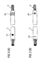
- Figs. 2(A) and 2(B) are enlarged views of a wire,
- Fig. 3 is a block diagram showing a wire harness producing method and a wire harness according to a second embodiment of the present invention,
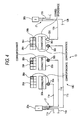
- Fig. 4 is a block diagram showing a wire harness producing method and a wire harness according to a third embodiment of the present invention,
- Figs. 5(A) and 5(B) are block diagrams showing a wire harness producing method and a wire harness according to a fourth embodiment of the present invention,
- Fig. 6 is a perspective view showing a conventional ordinary installation method, and
- Fig. 7 is an enlarged view of a proximal end terminal of wires.
- Referring to reference numerals in the drawings, 10A to 10D denote wire harnesses, 11 and 12 denote wires, 13 denotes a installation board, 14 denotes an open distal end, 20 denotes a bonder (proximal end terminal), 21 denotes an installation marking, 30 denotes a connector (connection terminal), and 31 denotes a proximal end terminal-indicating marking.
- A wire harness producing method and a wire harness according to a first embodiment of the present invention, will now be described in detail with reference to the drawings. Fig. 1 is an explanatory view showing the first embodiment of the wire harness producing method of the present invention.
- As shown in Fig. 1, a plurality of
bonders installation board 13.Installation markings 21 are provided respectively on those portions of a plurality ofwires first bonder 20a) disposed adjacent to their proximal ends, theinstallation markings 21 indicating whether these wires are to be installed to the right or the left from thebonder 20a. - Similarly,
Installation markings 21 are provided respectively on those portions of a plurality ofwires second bonder 20b) disposed adjacent to their proximal ends, theinstallation markings 21 indicating whether these wires are to be installed to the right or the left from thebonder 20a. - With respect to the
markings 21, for example, those wires to be installed to the left from thebonders mark 21a of a circle as shown in Fig. 2(A), while those wires to be installed to the right from thebonders mark 21b of X as shown in Fig. 2(B). - Therefore, among the
wires 11a to 11e extending from thefirst bonder 20a, thecircle mark 21a is provided on that portion of each of thewires - On the other hand, the
X mark 21b is provided on that portion of each of thewires -
Connectors installation board 13, and open distal ends 14 (see Fig. 2(A) and 2(B)) of thewires 11, each having a terminal connected thereto, are connected to theconnectors markings installation board 13, and are disposed near to theconnectors markings connector distal end 14 of eachwire 11 should be connected to. - Square sections, corresponding respectively to terminals of the
connector 30a, are provided at the proximal end terminal-indicating marking 31a provided near to theconnector 30a in Fig. 1, and the square sections indicate those wires 11 (extending respectively from the bonders 20) which should be connected to this connector. - Namely, there are indications that the
wire 11e, extending from thefirst bonder 20a, should be connected to the terminal corresponding to the square section (1) of the proximal end terminal-indicating marking 31a and that thewire 12a, extending from thesecond bonder 20b, should be connected to the terminal corresponding to the square section (2). - Next, the wire harness producing method of the present invention will be described. For forming the
wire harness 10A as shown in Fig. 1, thefirst bonder 20a and thesecond bonder 20b are mounted on theinstallation board 13 in such a manner that the two bonders are spaced a predetermined distance from each other. Also, theconnectors connectors - Among the plurality of
wires 11 extending from thefirst bonder 20a, thewires circle mark 21a at its proximal end terminal-adjacent portion, are installed in the left direction. Also, thewires X mark 21b at its proximal end terminal-adjacent portion, are installed in the right direction. - Although not shown, fork-like support members are provided at suitable intervals, and therefore the
wires 11 are supported by the support members. - The
wire 11e, installed to extend to the right from thefirst bonder 20a, is connected to theconnector 30a. At this time, thewire 11e is connected to the terminal of theconnector 30a which corresponds to the section of the proximal end terminal-indicating marking 31 a bearing the mark (1) indicative of thefirst bonder 20a. - Similarly, among the wires 12 extending from the
second bonder 20b, thewires circle mark 21a at its proximal end terminal-adjacent portion, are installed in the left direction, and thewire 12a is connected to theconnector 30a. - This wire is connected to the terminal which corresponds to the section of the proximal end terminal-indicating marking 31a bearing the mark (2) indicative of the
second bonder 20b. - In the manner described above, the
wire harness 10A is produced. - In the above wire harness producing method and the above wire harness, when installing the plurality of wires 11 (which have the same basic appearance, and extend from the same bonder 20) in their respective predetermined directions, each
wire 11 is installed in its predetermined direction according to the installation marking 20 (thecircle mark 21a or theX mark 21b) provided on its proximal end terminal-adjacent portion, and therefore each wire can be prevented from being installed in a wrong direction. - And besides, when connecting the
open distal ends 14 of the plurality ofwires 11, 12, extending from thebonders connectors connector installation board 13, and therefore a connection error can be prevented. - Next, the second embodiment will be described. Fig. 3 shows a wire harness producing method and a wire harness according to the second embodiment of the present invention.
- The same portions as those of the above-mentioned embodiment will be designated by identical reference numerals, respectively, and repeated explanation thereof will be omitted.
- As shown in Fig. 3,
installation markings 21, for example as shown in Fig. 2, are provided respectively on those portions of a plurality ofwires installation markings 21 indicating whether the wires are to be installed to the right or the left from the bonder 20. - Namely, a
circle mark 21a is provided on the proximal end terminal-adjacent portion of each of thewires X mark 21b is provided on the proximal end terminal-adjacent portion of each of thewires - Further, an identification marking 32 for identifying the
wire 11 is provided on that portion of eachwire 11 disposed adjacent to its opendistal end 14. With respect to the identification marking 32, for example as shown in Fig. 2(8), a pattern of horizontal-line hatching 32b indicative of thewire 11c is provided on thewire 11c. - Also, as shown in Fig. 2(A), a pattern of oblique-
line hatching 32a indicative of thewire 11d is provided on thewire 11d. With respect to the shape of the identification marking 32, the identification marking can be provided in a belt-like manner around the entire periphery as is the case with the identification marking 32a, or it can be provided in a predetermined shape as is the case with the identification marking 32b. The identification marking can be provided by printing or by winding a tape-like member on the wire. - Referring back to Fig. 3,
connectors installation board 13, and the open distal ends 14 of thewires connectors - The
connectors installation board 13. Wire-indicatingmarkings connectors markings connector distal end 14 of eachwire - Square sections, corresponding respectively to the terminals of the
connector 30a, are provided at the wire-indicatingmarking 33a provided near to theconnector 30a in Fig. 3, and this wire-indicating marking indicates a square section to which thewire 11d should be connected. Namely, amark 34a, having the same pattern as that of the identification marking 32a provided on thewire 11d, is provided on the square section corresponding to the terminal to which thewire 11d is to be connected. - For example, the
mark 34a, having the same horizontal-line hatching pattern as the oblique-line hatching pattern of the identification marking 32, is provided on the square section corresponding to the terminal of theconnector 30a to which thewire 11d (having the identification marking 32 of the oblique line-hatching pattern) is to be connected. Similarly, amark 34b, having a horizontal-line hatching pattern, is provided on the square section corresponding to the terminal of theconnector 30b to which thewire 11c (having the identification marking 32b of the horizontal line-hatching pattern) is to be connected. - Next, the wire harness producing method of the present invention will be described. For forming the
wire harness 10B as shown in Fig. 3, the bonder 20 is provided on theinstallation board 13, and theconnectors markings connectors - Among the plurality of
wires 11 extending from the bonder 20, thewires circle mark 21a at its proximal end terminal-adjacent portion, are installed in the left direction. Also, thewires X mark 21b at its proximal end terminal-adjacent portion, are installed in the right direction, and are supported by support members. - Each of the
wires connectors - At this time, the
wire 11c is connected to the terminal corresponding to the section of the wire-indicatingmarking 33b bearing themark 34b of the horizontal-line hatching pattern since the identification marking 32b of the horizontal-line hatching pattern is provided on thewire 11c. Similarly, thewire 11d, having the identification marking 32 of the oblique-line hatching pattern, is connected to the terminal corresponding to the section of the wire-indicatingmarking 33a bearing themark 34a of the oblique-line hatching pattern. - In the manner described above, the
wire harness 10B is produced. - In the above wire harness producing method and the above wire harness, when connecting the open distal ends 14 of the plurality of
wires 11, extending from the bonder 20, to either of the plurality ofconnectors wire 11 disposed adjacent to the opendistal end 14 thereof. Therefore, a connection error can be prevented. - Next, a third embodiment will be described. Fig. 4 shows a wire harness producing method and a wire harness which are provided in accordance with the third embodiment of the present invention.
- The same portions as those of the above-mentioned embodiments will be designated by identical reference numerals, respectively, and repeated explanation thereof will be omitted.
- As shown in Fig. 4, a plurality of
bonders installation board 13 in such a manner that these bonders are spaced a predetermined distance from each other.Installation markings 21 are provided respectively on those portions of a plurality ofwires first bonder 20a) disposed adjacent to the proximal end terminal. Similarly,installation markings 21 are provided respectively on those portions of a plurality ofwires second bonder 20b) disposed adjacent to the proximal end terminal. -
Connectors installation board 13, and open distal ends 14 of thewires connectors Indication markings installation board 13, and are disposed near to theconnectors distal end 14 of eachwire 11, 12 should be connected to. - Namely, the
indication markings - Therefore, square sections, corresponding respectively to terminals of each of the
connectors indication markings connectors identification markings wires wire first bonder 20a, or thewire 12a extending from thesecond bonder 20b. - Namely, the terminal position to which the wire is to be connected, the
wire 11 to be connected, and the bonder 20 at the proximal end of thiswire 11 can all be known from the indication marking 35. - Next, the third embodiment of the wire harness producing method of the present invention will be described.
- For forming the
wire harness 10C as shown in Fig. 4, thefirst bonder 20a and thesecond bonder 20b are mounted on theinstallation board 13 in such a manner that the two bonders are spaced a predetermined distance from each other. Theconnectors indication markings connectors - Among the plurality of
wires 11 extending from thefirst bonder 20a, thewires circle mark 21 a at its proximal end terminal-adjacent portion, are installed in the left direction. Also, thewires X mark 21b at its proximal end terminal-adjacent portion, are installed in the right direction, and are supported by support members. - Each of the
wires first bonder 20a, is connected to any of theconnectors wire 11 is installed and connected in such a manner that the identification marking 32, provided on thiswire 11, coincides with the pattern, numeral, etc., provided at the indication marking 35. - Similarly, among the plurality of wires 12 extending from the
second bonder 20b, thewires circle mark 21a at its proximal end terminal-adjacent portion, are installed in the left direction, and thewire 12a is connected to theconnector 30c. - In the manner described above, the
wire harness 10C is produced. - In the above wire harness producing method and the above wire harness, each
wire 11 is installed in the predetermined direction according to the installation marking 21 provided at the proximal end terminal-adjacent portion of thewire 11, and therefore each wire can be prevented from being installed in a wrong direction. - And besides, information as to the position of the terminal of the connector 30 to which the wire is to be connected, the bonder 20 to be connected to the connector, the
wire 11, 12 to be connected, etc., can be obtained from the indication marking 35 provided near to each connector 30 on theinstallation board 13, and therefore a connection error can be prevented. - Next, Figs. 5(a) and 5(b) show a wire harness producing method and a wire harness according to a fourth embodiment of the present invention.
- The same portions as those of the above-mentioned embodiments will be designated by identical reference numerals, respectively, and repeated explanation thereof will be omitted.
- As shown in Fig. 5(A), a
connector 42, serving as a proximal end terminal, is provided at a car stereosound system body 40, and four (front/rear and left/right)speakers - In a
wire harness 10D connecting theconnector 42 to the fourspeakers installation markings 21 are provided respectively on those portions ofwires 11 disposed adjacent to the proximal end terminal, as shown in Fig. 5(B). - Namely, for example, a
circle mark 21a, serving as the installation marking 21, is provided on each of thewires sound system body 40, while for example, anX mark 21b, serving as the installation marking 21, is provided on each of thewires - An indication marking 37a of right-upper oblique-line hatching indicative of the front-side speaker is provided on that portion of each of the
wires markings connectors side speakers - On the other hand, an indication marking 37b of left-upper oblique-line hatching indicative of the rear-side speaker is provided on that portion of each of the
wires markings connectors side speakers - Therefore, among the
wires 11 extending from theconnector 42 of the car stereosound system body 40, thewires circle mark 21a as the installation marking 21, are installed to the left, while thewires X mark 21b, are installed to the right. Each of thewires 11 is connected to the speaker 30 having the same marking as the identification marking 37 provided at that portion of thiswire 11 disposed adjacent to the open distal end thereof. - In the above wire harness producing method and the above wire harness, the
wires 11 are installed in their respective predetermined directions in accordance with theinstallation markings 21 provided respectively on the proximal end terminal-adjacent portions thereof, and therefore each wire can be prevented from being installed in a wrong direction. - And besides, thanks to the provision of the wire-indicating marking 33 at the connector 30 of each speaker 41, the
wire 11 to be connected thereto can be clearly identified, and therefore a connection error can be prevented. - The wire harness producing methods and wire harnesses of the present invention are not limited to the above embodiments, and suitable modifications, improvements and so on can be made.
- For example, although the above first to third embodiments have been described for the case where the proximal end terminal-indicating markings 31, the wire-indicating markings 33 and the indication markings 35 are provided on the
installation board 13, these markings can be provided on the connectors 30. As another alternative, these markings can be provided on both of theinstallation board 13 and the connectors 30. - Although the description has been made for the case where the
wires 11, extending from the bonder 20, are directed to the left and right, the invention can be similarly applied to the case where the wires are directed in many directions, In this case, with respect to theinstallation markings 21, there are providedinstallation markings 21 of different kinds corresponding in number to the installation directions. - The circle marks 21a and the X marks 21b used as the
installation markings 21, the horizontal-line hatching 34b and the oblique-line hatching 34a used as the wire-indicating markings 33, etc., are shown merely as examples, and the markings are not limited to these. - As described above, in the wire harness producing methods and the wire harnesses of the present invention, when the plurality of wires which have the same basic appearance, and extend from the common proximal end terminal are to be installed in their respective directions, each wire is installed according to the installation marking provided on the proximal end terminal-adjacent portion thereof, and therefore can be prevented from being installed in a wrong direction.
- Although the present invention has been described in detail by way of the specific embodiments, it will be clear to those versed in the art that various changes and modifications can be added without departing from the spirits and scope of the present invention.
- The present Application is based on a Japanese patent application (Japanese Patent Application No. 2003-123749), and contents of which are incorporated herein as a reference.
- The wire harness producing methods and the wire harnesses of the present invention are useful not only as wire harnesses used in a vehicle such as an automobile but also as wire harnesses used in various apparatuses.
Claims (5)
- A method of producing a wire harness, the wire harness being configured by wires having the same basic appearance, and the wires being installed over an installation board to extend in a plurality of directions from a common proximal end terminal, the method comprising:providing installation markings on those portions of the wires disposed adjacent to the proximal end terminal respectively beforehand, the installation markings indicating respective installation directions of the wires; andinstalling each of the wires in a desired direction from the proximal end terminal in accordance with each of the Installation markings.
- The method of producing the wire harness according to claim 1, in the case where a plurality of the proximal end terminals are used, and open distal ends of the wires extended from the proximal end terminals are connected to a connection terminal,
wherein a proximal end terminal-indicating marking is beforehand provided on at least one of the installation board and the connection terminal, the proximal end terminal-indicating marking indicating which section of the connection terminal the wire from any of the proximal end terminals is to be connected to; and
wherein the wire from the designated proximal end terminal is connected to the predetermined section of the connection terminal in accordance with the proximal end terminal-indicating marking. - The method of producing the wire harness according to claim 1 or 2, in the case where open distal ends of the wires are respectively connected to a plurality of different connection terminals,
wherein individual identification markings are beforehand provided on the open distal ends respectively;
wherein wire-indicating markings are beforehand provided on at least one of the installation board and the connection terminals, the wire-indicating markings being correspond respectively to the identification markings, and each indicating which section of the corresponding connection terminal any of the wires is to be connected to; and
wherein the open distal end of each of the wires is connected to the corresponding connection terminal In accordance with the wire-indicating marking. - The method of producing the wire harness according to any one of claims 1 to 3, wherein the proximal end terminal is a bonder joining earth wires together.
- A wire harness produced by the method of producing the wire harness as defined in any one of claims 1 to 4.
Applications Claiming Priority (2)
| Application Number | Priority Date | Filing Date | Title |
|---|---|---|---|
| JP2003123749A JP2004327372A (en) | 2003-04-28 | 2003-04-28 | Manufacturing method of wire harness and wire harness |
| PCT/JP2004/006068 WO2004097856A1 (en) | 2003-04-28 | 2004-04-27 | Wire harness manufacturing method and wire harness |
Publications (2)
| Publication Number | Publication Date |
|---|---|
| EP1622172A1 true EP1622172A1 (en) | 2006-02-01 |
| EP1622172A4 EP1622172A4 (en) | 2008-07-02 |
Family
ID=33410136
Family Applications (1)
| Application Number | Title | Priority Date | Filing Date |
|---|---|---|---|
| EP04729741A Withdrawn EP1622172A4 (en) | 2003-04-28 | 2004-04-27 | METHOD FOR MANUFACTURING WIRE BEAMS AND WIRE BEAMS |
Country Status (5)
| Country | Link |
|---|---|
| EP (1) | EP1622172A4 (en) |
| JP (1) | JP2004327372A (en) |
| CN (1) | CN100426422C (en) |
| MX (1) | MXPA05011602A (en) |
| WO (1) | WO2004097856A1 (en) |
Cited By (2)
| Publication number | Priority date | Publication date | Assignee | Title |
|---|---|---|---|---|
| US20150162728A1 (en) * | 2012-07-04 | 2015-06-11 | Siemens Aktiengesellschaft | Method for producing sub-assemblies |
| EP3208790A1 (en) | 2016-02-22 | 2017-08-23 | Robin Reimers | Conductor marking system and method |
Families Citing this family (5)
| Publication number | Priority date | Publication date | Assignee | Title |
|---|---|---|---|---|
| CN102371565A (en) * | 2010-08-24 | 2012-03-14 | 上海李尔实业交通汽车部件有限公司 | Device for mounting and detecting wire harness fastener |
| CN103522870B (en) * | 2013-11-06 | 2015-07-22 | 重庆龙润汽车转向器有限公司 | Front evaporator assembly of automobile air conditioner |
| CN103560378A (en) * | 2013-11-11 | 2014-02-05 | 安徽金光神特种电缆有限公司 | Wire harness graph representing method |
| JP6369762B2 (en) * | 2016-05-11 | 2018-08-08 | 日立金属株式会社 | Wire harness manufacturing equipment |
| JP7054328B2 (en) * | 2017-09-11 | 2022-04-13 | Koa株式会社 | Sensor unit and multiple sensors using it |
Family Cites Families (9)
| Publication number | Priority date | Publication date | Assignee | Title |
|---|---|---|---|---|
| WO1981001343A1 (en) * | 1979-11-02 | 1981-05-14 | Mitsubishi Electric Corp | Wiring harness |
| JPH1125781A (en) * | 1997-07-03 | 1999-01-29 | Sumitomo Wiring Syst Ltd | Temporary binding sub harness and manufacture of wire harness |
| DE19918212A1 (en) * | 1999-04-22 | 2000-11-09 | Cad Cabel Inh Peter Hanzel | Cables for wiring electrical devices of a complex, individual system and process for their manufacture |
| FR2808374A1 (en) * | 2000-04-27 | 2001-11-02 | Labinal | INSTALLATION FOR MANUFACTURING A WIRING HARNESS |
| JP2002109975A (en) * | 2000-09-28 | 2002-04-12 | Sumitomo Wiring Syst Ltd | Wiring jig for wiring harness |
| JP4644977B2 (en) * | 2001-06-12 | 2011-03-09 | 住友電装株式会社 | Electric wire for automobile |
| JP2003059353A (en) * | 2001-08-10 | 2003-02-28 | Sumitomo Wiring Syst Ltd | Connector connection method, connection structure of wire for automobile |
| JP2003061234A (en) * | 2001-08-10 | 2003-02-28 | Sumitomo Wiring Syst Ltd | Method of setting arrangement pattern of automotive wires in connector and structure for connecting wires to connector |
| WO2003031094A1 (en) * | 2001-10-11 | 2003-04-17 | Laser Projection Technologies, Inc. | Projection wire harness routing table system |
-
2003
- 2003-04-28 JP JP2003123749A patent/JP2004327372A/en active Pending
-
2004
- 2004-04-27 CN CNB2004800115832A patent/CN100426422C/en not_active Expired - Fee Related
- 2004-04-27 MX MXPA05011602A patent/MXPA05011602A/en active IP Right Grant
- 2004-04-27 EP EP04729741A patent/EP1622172A4/en not_active Withdrawn
- 2004-04-27 WO PCT/JP2004/006068 patent/WO2004097856A1/en not_active Ceased
Cited By (5)
| Publication number | Priority date | Publication date | Assignee | Title |
|---|---|---|---|---|
| US20150162728A1 (en) * | 2012-07-04 | 2015-06-11 | Siemens Aktiengesellschaft | Method for producing sub-assemblies |
| US9768595B2 (en) * | 2012-07-04 | 2017-09-19 | Siemens Aktiengeselschaft | Method for producing sub-assemblies |
| EP3208790A1 (en) | 2016-02-22 | 2017-08-23 | Robin Reimers | Conductor marking system and method |
| DE102016103062A1 (en) * | 2016-02-22 | 2017-08-24 | Robin Reimers | Line marking system and method |
| DE102016103062B4 (en) | 2016-02-22 | 2019-01-10 | Robin Reimers | Line marking system and method |
Also Published As
| Publication number | Publication date |
|---|---|
| CN1781163A (en) | 2006-05-31 |
| MXPA05011602A (en) | 2005-12-15 |
| WO2004097856A1 (en) | 2004-11-11 |
| CN100426422C (en) | 2008-10-15 |
| EP1622172A4 (en) | 2008-07-02 |
| JP2004327372A (en) | 2004-11-18 |
Similar Documents
| Publication | Publication Date | Title |
|---|---|---|
| EP1033786B1 (en) | Modular splicing connector | |
| US8513526B2 (en) | Wiring harness | |
| EP0734097A1 (en) | A circuit member and an electrical connection box | |
| US11146020B2 (en) | Wire harness including a connector holder | |
| US8895854B2 (en) | Wiring harness and manufacturing method thereof | |
| EP1267364A2 (en) | Color arrangement of electrical cables e.g. for automobiles | |
| EP1273481A2 (en) | Rotary connector equipped with versatile lead block | |
| EP1622171A1 (en) | Electric wire, electric wire connection method, and wire harness | |
| CN100426422C (en) | Method for producing a wire harness and wire harness | |
| CN114256791A (en) | Wire harness | |
| JP3694207B2 (en) | Method for manufacturing tape electric wire with terminal and method for manufacturing wire harness | |
| JP2003168329A (en) | Covered electric wire | |
| JP2009055726A (en) | Fixed structure for linear objects | |
| JP2009301944A (en) | Adhesive tape to be wound around electric wires, and wire harness wound with the adhesive tape | |
| US20060118323A1 (en) | Wire harness with concentric code identifier | |
| JPH0973820A (en) | Electric cable and wiring method therefor | |
| US12504439B2 (en) | Coil body, inductive rotational speed sensor, and method for producing the same | |
| US20250293474A1 (en) | Terminal assembly for a directionally dependent sensor, directionally dependent sensor, and method for manufacturing the terminal assembly | |
| CN212783907U (en) | Multi-coaxial contact guiding tool | |
| KR20240114915A (en) | Wire harness production method displaying assembly information and wire harness produced there of | |
| JP5993662B2 (en) | Vehicle panel | |
| JP2003109706A (en) | Terminal for multi-channel speaker and plug for speaker cable | |
| US6746271B2 (en) | Electrical plug connection having an adjustable coding | |
| JP3878511B2 (en) | Terminal insertion jig | |
| US20020167308A1 (en) | Miniaturized positional assembly and method of manufacturing |
Legal Events
| Date | Code | Title | Description |
|---|---|---|---|
| PUAI | Public reference made under article 153(3) epc to a published international application that has entered the european phase |
Free format text: ORIGINAL CODE: 0009012 |
|
| 17P | Request for examination filed |
Effective date: 20051027 |
|
| AK | Designated contracting states |
Kind code of ref document: A1 Designated state(s): PT SK |
|
| AX | Request for extension of the european patent |
Extension state: LT |
|
| RAX | Requested extension states of the european patent have changed |
Extension state: LT Payment date: 20051027 |
|
| RBV | Designated contracting states (corrected) |
Designated state(s): PT SK |
|
| A4 | Supplementary search report drawn up and despatched |
Effective date: 20080603 |
|
| STAA | Information on the status of an ep patent application or granted ep patent |
Free format text: STATUS: THE APPLICATION HAS BEEN WITHDRAWN |
|
| 18W | Application withdrawn |
Effective date: 20150818 |