EP1621936A1 - Corona charging device with an electrical connector assembly - Google Patents
Corona charging device with an electrical connector assembly Download PDFInfo
- Publication number
- EP1621936A1 EP1621936A1 EP05106843A EP05106843A EP1621936A1 EP 1621936 A1 EP1621936 A1 EP 1621936A1 EP 05106843 A EP05106843 A EP 05106843A EP 05106843 A EP05106843 A EP 05106843A EP 1621936 A1 EP1621936 A1 EP 1621936A1
- Authority
- EP
- European Patent Office
- Prior art keywords
- pin
- charging device
- corona
- corona member
- scorotron
- Prior art date
- Legal status (The legal status is an assumption and is not a legal conclusion. Google has not performed a legal analysis and makes no representation as to the accuracy of the status listed.)
- Granted
Links
- 108091008695 photoreceptors Proteins 0.000 description 13
- 238000003384 imaging method Methods 0.000 description 7
- 238000002955 isolation Methods 0.000 description 6
- 239000004020 conductor Substances 0.000 description 4
- 230000005684 electric field Effects 0.000 description 3
- 239000000463 material Substances 0.000 description 3
- 238000000034 method Methods 0.000 description 3
- 239000002245 particle Substances 0.000 description 3
- 239000002184 metal Substances 0.000 description 2
- 238000004140 cleaning Methods 0.000 description 1
- 150000002500 ions Chemical class 0.000 description 1
- 108020003175 receptors Proteins 0.000 description 1
Images



Classifications
-
- G—PHYSICS
- G03—PHOTOGRAPHY; CINEMATOGRAPHY; ANALOGOUS TECHNIQUES USING WAVES OTHER THAN OPTICAL WAVES; ELECTROGRAPHY; HOLOGRAPHY
- G03G—ELECTROGRAPHY; ELECTROPHOTOGRAPHY; MAGNETOGRAPHY
- G03G15/00—Apparatus for electrographic processes using a charge pattern
- G03G15/80—Details relating to power supplies, circuits boards, electrical connections
-
- G—PHYSICS
- G03—PHOTOGRAPHY; CINEMATOGRAPHY; ANALOGOUS TECHNIQUES USING WAVES OTHER THAN OPTICAL WAVES; ELECTROGRAPHY; HOLOGRAPHY
- G03G—ELECTROGRAPHY; ELECTROPHOTOGRAPHY; MAGNETOGRAPHY
- G03G15/00—Apparatus for electrographic processes using a charge pattern
- G03G15/02—Apparatus for electrographic processes using a charge pattern for laying down a uniform charge, e.g. for sensitising; Corona discharge devices
- G03G15/0283—Arrangements for supplying power to the sensitising device
-
- G—PHYSICS
- G03—PHOTOGRAPHY; CINEMATOGRAPHY; ANALOGOUS TECHNIQUES USING WAVES OTHER THAN OPTICAL WAVES; ELECTROGRAPHY; HOLOGRAPHY
- G03G—ELECTROGRAPHY; ELECTROPHOTOGRAPHY; MAGNETOGRAPHY
- G03G15/00—Apparatus for electrographic processes using a charge pattern
- G03G15/02—Apparatus for electrographic processes using a charge pattern for laying down a uniform charge, e.g. for sensitising; Corona discharge devices
- G03G15/0291—Apparatus for electrographic processes using a charge pattern for laying down a uniform charge, e.g. for sensitising; Corona discharge devices corona discharge devices, e.g. wires, pointed electrodes, means for cleaning the corona discharge device
-
- G—PHYSICS
- G03—PHOTOGRAPHY; CINEMATOGRAPHY; ANALOGOUS TECHNIQUES USING WAVES OTHER THAN OPTICAL WAVES; ELECTROGRAPHY; HOLOGRAPHY
- G03G—ELECTROGRAPHY; ELECTROPHOTOGRAPHY; MAGNETOGRAPHY
- G03G2215/00—Apparatus for electrophotographic processes
- G03G2215/02—Arrangements for laying down a uniform charge
- G03G2215/026—Arrangements for laying down a uniform charge by coronas
- G03G2215/028—Arrangements for laying down a uniform charge by coronas using pointed electrodes
Definitions
- the present disclosure relates to xerographic printing apparatus, and particularly to a connector by which a charging device, such as a corotron or a scorotron, is connected to a voltage source within a machine.
- a charging device such as a corotron or a scorotron
- an electrostatic latent image is formed on a charge-retentive imaging surface, typically a "photoreceptor,” and then developed with an application of toner particles.
- the toner particles adhere electrostatically to the suitably-charged portions of the photoreceptor.
- the toner particles are then transferred, by the application of electric charge, to a print sheet, forming the desired image on the print sheet.
- An electric charge can also be used to separate or "detack" the print sheet from the photoreceptor.
- the most typical device for applying a predetermined charge to the imaging surface is a "corotron,” of which there are any number of variants, such as the scorotron or dicorotron.
- corotron Common to most types of corotron is one or more bare conductors, in proximity to the imaging surface, which is electrically biased and thereby supplies ions for charging the imaging surface.
- the conductor typically comprises a wire (often called a "corona wire") or a metal bar or ribbon forming saw-teeth (a "pin array”).
- the conductor extends parallel to the imaging surface and along a direction perpendicular to a direction of motion of the imaging surface.
- corotron having a screen or grid disposed between the conductor and the photoreceptor is typically known as a "scorotron".
- the present disclosure relates to a connector by which a charging device, such as a corotron or a scorotron, is connected to a voltage source within a xerographic printing machine.
- a charging device such as a corotron or a scorotron
- a charging device useful in an electrostatographic printing apparatus, comprising a first corona member and a second corona member.
- An end block defines at least two channels therein, each channel substantially encasing a portion of a corona member.
- a conductive pin is anchored in the end block.
- Each of the first corona member and second corona member define an opening engaging a portion of the conductive pin.
- a cover block substantially covers the channels in the end block.
- the cover block defines a collar substantially surrounding a portion of the pin.
- at least one of the cover block and the end block include a detent for enabling the cover block and the end block to snap together.
- the present invention relates to an apparatus according to claim 10.
- the is a replaceable unit which fits into a larger machine.
- Figure 1 is a simplified, elevational, sectional view showing certain elements of an electrostatographic or xerographic printing apparatus.
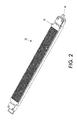
- Figure 2 shows a scorotron in isolation.
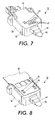
- Figures 3-4 and 7-8 are a series of perspective views showing one end of a scorotron, in various stages of assembly.
- Figure 5 shows an end of corona member in isolation.
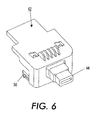
- Figure 6 shows an end block in isolation
- FIG. 1 is a simplified, elevational, sectional view showing certain elements of an electrostatographic or xerographic printing apparatus, generally indicated as 100.
- electrostatic latent images are created on a rotating charge receptor, such as shown as photoreceptor 102, which is here shown as a drum but in other designs could be in the form of a belt.
- photoreceptor 102 which is here shown as a drum but in other designs could be in the form of a belt.
- Various stations familiar in xerography, such as exposure, development, and cleaning stations, are arranged around the photoreceptor 102.
- the term "printing apparatus” can refer either to an entire printing machine or copier, or to a replaceable unit, such as including a photoreceptor as well, that fits into a larger machine.
- the scorotron 10 includes, in this embodiment, three “corona members" 20, 22, 24, each of which is a bare conductive member, such as a wire or a ribbon, which emits an electric field when it is electrically biased (by means not shown). Interposed between the corona members 20, 22, 24 and the adjacent surface of photoreceptor 102 is a screen 26, which may be externally biased as well to aid in directing electric fields from the corona members 20, 22, 24 to the photoreceptor 102.
- FIG. 2 shows a scorotron 10 in isolation.
- the corona members (not visible in this view) and the screen 26 (which can be considered part of the scorotron 10) extend the width of the photoreceptor 102 when the scorotron 10 is installed in printing apparatus 100.
- An electrical connection can be made from scorotron 10 to a voltage source within apparatus 100, such as through pin 40, which will be described in detail below.
- FIGS 3-4 and 7-8 are a series of perspective views showing one end of scorotron 10, in various stages of assembly.
- the end of the scorotron 10 shown in the Figures is the end at which the corona members 20, 22, 24 are electrically connected to a voltage source (not shown) inside printing apparatus 100.
- the main piece at the end of scorotron 10 can be called an end block 28.
- the end block 28 is made largely of an insulative material, such as plastic.
- the end block 28 defines, in this embodiment, three distinct channels therein, indicated as 30, 32, and 34.
- each of the corona members 20, 22, 24 is in the form of a conductive ribbon defining, along a main length thereof, a series of regularly-spaced sawtooth pins.
- the portion of each corona member 20, 22, 24 disposed within end block 28 does not define sawtooth pins, but extends through one of the respective channels 30, 32, 34.
- Each channel should substantially encase a portion of one corona member 20, 22, 24: the channel does not have to contact the corona member, but should be closely spaced therefrom.
- a conductive pin 40 in the form of a flat spade, which is shown partially withdrawn from end block 28 in Figure 3 and fully anchored in Figure 4.
- the "profile" of the pin 40 meaning its shape along a section thereof, is not round; i.e., pin 40 in this embodiment is not a cylinder or screw.
- a portion of pin 40 passes through an opening 21 defined at the end of corona member 20.
- the opening 21 is aligned with a similar opening 23 at the end of corona member 22 and an opening 25 at the end of corona member 24. Pin 40 thus passes through all openings 21, 23, and 25.
- FIG. 5 shows an end of corona member 20 in isolation, showing the shape of opening 21; similar openings are present in the other corona members.
- Opening 21 has a "dog-bone” shape, forming flaps 26.
- the flaps 26 are sized and shaped to bend when the pin 40 is inserted into opening 21, so that the flaps 26 are bent against the pin 40 when the assembly is complete; the resilience of the metal of the corona member such as 20 causes the bent flaps to urge against the pin 40.
- the openings 23, 25 in corona members 22 and 24 are also aligned to accept the pin 40 therethrough, and the equivalent flaps of each opening are thus urged against a portion of pin 40.
- Figure 6 shows a "cover block,” generally indicated as 42, in isolation.
- Cover block 42 which can be made from a single piece of insulative material such as plastic, defines a collar 44 and a set of lugs 46.
- Figure 7 shows a further step in the assembly process, following that shown in Figure 4.
- cover block 42 is placed over the end block 28, in effect covering the channels 30, 32, 34, while collar 44 surrounds a portion of pin 40.
- cover block 42 further includes at least one flexible detent 50, which corresponds to a notch 52 in end block 28; the combination of the detent 50 and notch 52 enable the end block 28 and cover block 42 to snap together securely, typically without a need for tools.
- FIG 8 shows a further step in the assembly process
- lugs 46 fit into openings 48 in the screen 26.
- the lugs 46 can be notched, as shown, so as to place a small tension on the screen 26 as it is mounted on the body of scorotron 10.
- Further structures, such as smaller lugs 47 between lugs 46 in Figure 6, can be provided to maintain a desirable spacing between screen 26 and the rest of the scorotron 10.
Landscapes
- Physics & Mathematics (AREA)
- Engineering & Computer Science (AREA)
- Plasma & Fusion (AREA)
- General Physics & Mathematics (AREA)
- Electrostatic Charge, Transfer And Separation In Electrography (AREA)
Abstract
Description
- The present disclosure relates to xerographic printing apparatus, and particularly to a connector by which a charging device, such as a corotron or a scorotron, is connected to a voltage source within a machine.
- In the well-known process of electrostatographic or xerographic printing, an electrostatic latent image is formed on a charge-retentive imaging surface, typically a "photoreceptor," and then developed with an application of toner particles. The toner particles adhere electrostatically to the suitably-charged portions of the photoreceptor. The toner particles are then transferred, by the application of electric charge, to a print sheet, forming the desired image on the print sheet. An electric charge can also be used to separate or "detack" the print sheet from the photoreceptor.
- For the initial charging, transfer, or detack of an imaging surface, the most typical device for applying a predetermined charge to the imaging surface is a "corotron," of which there are any number of variants, such as the scorotron or dicorotron. Common to most types of corotron is one or more bare conductors, in proximity to the imaging surface, which is electrically biased and thereby supplies ions for charging the imaging surface. The conductor typically comprises a wire (often called a "corona wire") or a metal bar or ribbon forming saw-teeth (a "pin array"). The conductor extends parallel to the imaging surface and along a direction perpendicular to a direction of motion of the imaging surface. Other structures, such as a screen, conductive shield and/or nonconductive housing, are typically present in a charging device, and some of these may be electrically biased as well. A corotron having a screen or grid disposed between the conductor and the photoreceptor is typically known as a "scorotron".
- The present disclosure relates to a connector by which a charging device, such as a corotron or a scorotron, is connected to a voltage source within a xerographic printing machine.
- According to one aspect, there is provided a charging device useful in an electrostatographic printing apparatus, comprising a first corona member and a second corona member. An end block defines at least two channels therein, each channel substantially encasing a portion of a corona member. A conductive pin is anchored in the end block. Each of the first corona member and second corona member define an opening engaging a portion of the conductive pin. A cover block substantially covers the channels in the end block.
In a further embodiment, the cover block defines a collar substantially surrounding a portion of the pin.
In a further embodiment at least one of the cover block and the end block include a detent for enabling the cover block and the end block to snap together.
According to a further aspect the present invention relates to an apparatus according toclaim 10.
In a further embodiment the is a replaceable unit which fits into a larger machine. - Figure 1 is a simplified, elevational, sectional view showing certain elements of an electrostatographic or xerographic printing apparatus.
- Figure 2 shows a scorotron in isolation.
- Figures 3-4 and 7-8 are a series of perspective views showing one end of a scorotron, in various stages of assembly.
- Figure 5 shows an end of corona member in isolation.
- Figure 6 shows an end block in isolation.
- Figure 1 is a simplified, elevational, sectional view showing certain elements of an electrostatographic or xerographic printing apparatus, generally indicated as 100. As is well known, electrostatic latent images are created on a rotating charge receptor, such as shown as
photoreceptor 102, which is here shown as a drum but in other designs could be in the form of a belt. Various stations (not shown) familiar in xerography, such as exposure, development, and cleaning stations, are arranged around thephotoreceptor 102. As used herein, the term "printing apparatus" can refer either to an entire printing machine or copier, or to a replaceable unit, such as including a photoreceptor as well, that fits into a larger machine. - At some locations around the
photoreceptor 102 it is desired to direct one or more electric fields toward the photoreceptor. Typically such stations are for initial charging or for transfer of marking material from the photoreceptor to a print sheet. In either case, a common device used for this purpose is called a "scorotron", an example of which is shown as 10. Thescorotron 10 includes, in this embodiment, three "corona members" 20, 22, 24, each of which is a bare conductive member, such as a wire or a ribbon, which emits an electric field when it is electrically biased (by means not shown). Interposed between thecorona members photoreceptor 102 is ascreen 26, which may be externally biased as well to aid in directing electric fields from thecorona members photoreceptor 102. - Figure 2 shows a
scorotron 10 in isolation. The corona members (not visible in this view) and the screen 26 (which can be considered part of the scorotron 10) extend the width of thephotoreceptor 102 when thescorotron 10 is installed inprinting apparatus 100. An electrical connection can be made fromscorotron 10 to a voltage source withinapparatus 100, such as throughpin 40, which will be described in detail below. - Figures 3-4 and 7-8 are a series of perspective views showing one end of
scorotron 10, in various stages of assembly. The end of thescorotron 10 shown in the Figures is the end at which thecorona members printing apparatus 100. - The main piece at the end of
scorotron 10 can be called anend block 28. Theend block 28 is made largely of an insulative material, such as plastic. Theend block 28 defines, in this embodiment, three distinct channels therein, indicated as 30, 32, and 34. Further in this embodiment, each of thecorona members corona member end block 28 does not define sawtooth pins, but extends through one of therespective channels corona member - Anchored within
end block 28 is aconductive pin 40, in the form of a flat spade, which is shown partially withdrawn fromend block 28 in Figure 3 and fully anchored in Figure 4. The "profile" of thepin 40, meaning its shape along a section thereof, is not round; i.e.,pin 40 in this embodiment is not a cylinder or screw. As can be seen in Figure 3, a portion ofpin 40 passes through anopening 21 defined at the end ofcorona member 20. Although it cannot be clearly shown, the opening 21 is aligned with a similar opening 23 at the end ofcorona member 22 and an opening 25 at the end ofcorona member 24.Pin 40 thus passes through allopenings 21, 23, and 25. - Figure 5 shows an end of
corona member 20 in isolation, showing the shape of opening 21; similar openings are present in the other corona members.Opening 21 has a "dog-bone" shape, formingflaps 26. Theflaps 26 are sized and shaped to bend when thepin 40 is inserted into opening 21, so that theflaps 26 are bent against thepin 40 when the assembly is complete; the resilience of the metal of the corona member such as 20 causes the bent flaps to urge against thepin 40. In the complete assembly, the openings 23, 25 incorona members pin 40 therethrough, and the equivalent flaps of each opening are thus urged against a portion ofpin 40. - Figure 6 shows a "cover block," generally indicated as 42, in isolation.
Cover block 42, which can be made from a single piece of insulative material such as plastic, defines acollar 44 and a set oflugs 46. Figure 7 shows a further step in the assembly process, following that shown in Figure 4. In Figure 7,cover block 42 is placed over theend block 28, in effect covering thechannels collar 44 surrounds a portion ofpin 40. As can be seen in Figures 6 and 7,cover block 42 further includes at least oneflexible detent 50, which corresponds to anotch 52 inend block 28; the combination of the detent 50 andnotch 52 enable theend block 28 andcover block 42 to snap together securely, typically without a need for tools. - Turning to Figure 8, which shows a further step in the assembly process, it can be seen that lugs 46 fit into
openings 48 in thescreen 26. Thelugs 46 can be notched, as shown, so as to place a small tension on thescreen 26 as it is mounted on the body ofscorotron 10. Further structures, such assmaller lugs 47 betweenlugs 46 in Figure 6, can be provided to maintain a desirable spacing betweenscreen 26 and the rest of thescorotron 10.
Claims (10)
- A charging device useful in a printing apparatus, comprising:a first corona member and a second corona member;an end block defining at least two channels therein, each channel substantially encasing a portion of a corona member;a conductive pin, a portion of the pin anchored in the end block;each of the first corona member and second corona member defining an opening engaging a portion of the conductive pin; anda cover block, substantially covering the channels in the end block.
- The charging device of claim 1, the pin having a non-round profile.
- The charging device of claim 1, the opening in the first corona member being aligned with the opening in the second corona member.
- The charging device of claim 1, the opening in the first corona member defining at least one flap which is bent against the pin.
- The charging device of claim 4, the opening in the second corona member defining at least one flap which is bent against the pin.
- The charging device of claim 1, the first corona member including a substantially flat ribbon.
- The charging device of claim 6, a pin array being defined in the ribbon.
- The charging device of claim 1, at least one of the cover block and the end block defining at least one lug; and further comprising
a screen, at least a portion of the screen being mounted on the lug. - The charging device of claim 8, the lug defining a notch, suitable for holding the screen at a predetermined tension.
- A printing apparatus, comprising:a charge receptor; and
a charging device according to any of claims 1 to 9.
Applications Claiming Priority (1)
| Application Number | Priority Date | Filing Date | Title |
|---|---|---|---|
| US10/899,346 US7136612B2 (en) | 2004-07-26 | 2004-07-26 | Connection assembly for a xerographic charging device |
Publications (2)
| Publication Number | Publication Date |
|---|---|
| EP1621936A1 true EP1621936A1 (en) | 2006-02-01 |
| EP1621936B1 EP1621936B1 (en) | 2009-03-04 |
Family
ID=35045158
Family Applications (1)
| Application Number | Title | Priority Date | Filing Date |
|---|---|---|---|
| EP05106843A Expired - Lifetime EP1621936B1 (en) | 2004-07-26 | 2005-07-26 | Corona charging device with an electrical connector assembly |
Country Status (7)
| Country | Link |
|---|---|
| US (1) | US7136612B2 (en) |
| EP (1) | EP1621936B1 (en) |
| JP (1) | JP2006039548A (en) |
| CN (1) | CN100429580C (en) |
| BR (1) | BRPI0502846A (en) |
| DE (1) | DE602005013030D1 (en) |
| MX (1) | MXPA05007780A (en) |
Families Citing this family (4)
| Publication number | Priority date | Publication date | Assignee | Title |
|---|---|---|---|---|
| US7149458B2 (en) * | 2005-02-28 | 2006-12-12 | Xerox Corporation | Xerographic charging device having three pin arrays |
| US20060280531A1 (en) * | 2005-06-10 | 2006-12-14 | Xerox Corporation | Transfer-detack assembly for a xerographic printer |
| US9968804B2 (en) * | 2016-01-14 | 2018-05-15 | Reliance Industries, Llc | Nozzle for retractable fall arrest |
| US11340535B1 (en) | 2021-03-15 | 2022-05-24 | Palo Alto Research Center Incorporated | Fountain jet image formation on charged image surface |
Citations (3)
| Publication number | Priority date | Publication date | Assignee | Title |
|---|---|---|---|---|
| US4110811A (en) * | 1977-05-31 | 1978-08-29 | Xerox Corporation | Support structure for a corona generating device |
| US5257073A (en) * | 1992-07-01 | 1993-10-26 | Xerox Corporation | Corona generating device |
| US5909608A (en) * | 1998-01-07 | 1999-06-01 | Xerox Corporation | Tension support mounting for a corona generating device |
Family Cites Families (7)
| Publication number | Priority date | Publication date | Assignee | Title |
|---|---|---|---|---|
| US4575221A (en) * | 1982-05-20 | 1986-03-11 | Canon Kabushiki Kaisha | Process kit and an image forming apparatus using the same |
| US5079668A (en) * | 1989-02-10 | 1992-01-07 | Mita Industrial Co., Ltd. | Corona discharging device |
| JPH05303261A (en) * | 1992-04-24 | 1993-11-16 | Ricoh Co Ltd | Grid tension structure of scorotron charger |
| US5539205A (en) * | 1995-01-30 | 1996-07-23 | Xerox Corporation | Corona generating device and method of fabricating |
| JP3521371B2 (en) * | 1996-01-10 | 2004-04-19 | コニカミノルタホールディングス株式会社 | Corona charging device for image forming equipment |
| JPH10186798A (en) * | 1996-12-24 | 1998-07-14 | Ricoh Co Ltd | Corona discharge device |
| US6937835B2 (en) * | 2002-08-28 | 2005-08-30 | Seiko Epson Corporation | Developer charging unit, developing device, image-forming apparatus, and computer system |
-
2004
- 2004-07-26 US US10/899,346 patent/US7136612B2/en not_active Expired - Lifetime
-
2005
- 2005-07-19 JP JP2005208055A patent/JP2006039548A/en not_active Withdrawn
- 2005-07-21 MX MXPA05007780A patent/MXPA05007780A/en active IP Right Grant
- 2005-07-25 BR BRPI0502846-9A patent/BRPI0502846A/en not_active IP Right Cessation
- 2005-07-26 DE DE602005013030T patent/DE602005013030D1/en not_active Expired - Lifetime
- 2005-07-26 CN CNB2005100845441A patent/CN100429580C/en not_active Expired - Fee Related
- 2005-07-26 EP EP05106843A patent/EP1621936B1/en not_active Expired - Lifetime
Patent Citations (3)
| Publication number | Priority date | Publication date | Assignee | Title |
|---|---|---|---|---|
| US4110811A (en) * | 1977-05-31 | 1978-08-29 | Xerox Corporation | Support structure for a corona generating device |
| US5257073A (en) * | 1992-07-01 | 1993-10-26 | Xerox Corporation | Corona generating device |
| US5909608A (en) * | 1998-01-07 | 1999-06-01 | Xerox Corporation | Tension support mounting for a corona generating device |
Also Published As
| Publication number | Publication date |
|---|---|
| CN100429580C (en) | 2008-10-29 |
| US20060018682A1 (en) | 2006-01-26 |
| US7136612B2 (en) | 2006-11-14 |
| DE602005013030D1 (en) | 2009-04-16 |
| BRPI0502846A (en) | 2006-03-07 |
| EP1621936B1 (en) | 2009-03-04 |
| CN1728007A (en) | 2006-02-01 |
| MXPA05007780A (en) | 2006-01-30 |
| JP2006039548A (en) | 2006-02-09 |
Similar Documents
| Publication | Publication Date | Title |
|---|---|---|
| US10698357B2 (en) | Image forming apparatus in which cost of component and assembling caused by sorting work is reduced by providing electrically conductive wire formed of material having elastic coefficient lower than first and second urging members | |
| EP1016939A3 (en) | Image developing apparatus, process cartridge, electrophotographic image forming apparatus, and development unit frame | |
| KR101586472B1 (en) | Image forming apparatus | |
| JP5162140B2 (en) | Developing device in image forming apparatus | |
| US7136612B2 (en) | Connection assembly for a xerographic charging device | |
| JPH0760282B2 (en) | Image forming device | |
| US5909608A (en) | Tension support mounting for a corona generating device | |
| US7149458B2 (en) | Xerographic charging device having three pin arrays | |
| US8126367B2 (en) | Scorotron apparatus for charging a photoconductor | |
| EP1617295B1 (en) | Charging device for xerographic printing having two pin arrays | |
| US7933537B2 (en) | Xerographic charging device having planar two pin arrays | |
| US5812359A (en) | Method and apparatus for lightweight corona device shield mounting | |
| JP7306182B2 (en) | Connection structure and image forming apparatus | |
| JP2890299B2 (en) | Image forming device | |
| CN110018622A (en) | Electric connection construction and image forming apparatus | |
| JP2005266545A (en) | Electrifying apparatus in image forming apparatus | |
| JP2021048080A (en) | Electrical connection structure and image formation device | |
| JP2005274669A (en) | Image forming apparatus | |
| JPH0546000A (en) | Electrophotographic device | |
| JPH0714459U (en) | Corona transfer device | |
| US20060269326A1 (en) | Dicorotron having a shield insert | |
| JPS6294864A (en) | High voltage power source connecting device for copying machine | |
| JPS59228283A (en) | Photosensitive body grounding device of electrophotographic copying machine | |
| JPH08262837A (en) | Corona discharger for image forming device | |
| JPS63108367A (en) | Electrostatic charger |
Legal Events
| Date | Code | Title | Description |
|---|---|---|---|
| PUAI | Public reference made under article 153(3) epc to a published international application that has entered the european phase |
Free format text: ORIGINAL CODE: 0009012 |
|
| AK | Designated contracting states |
Kind code of ref document: A1 Designated state(s): AT BE BG CH CY CZ DE DK EE ES FI FR GB GR HU IE IS IT LI LT LU LV MC NL PL PT RO SE SI SK TR |
|
| AX | Request for extension of the european patent |
Extension state: AL BA HR MK YU |
|
| 17P | Request for examination filed |
Effective date: 20060801 |
|
| 17Q | First examination report despatched |
Effective date: 20060830 |
|
| AKX | Designation fees paid |
Designated state(s): DE FR GB |
|
| 17Q | First examination report despatched |
Effective date: 20060830 |
|
| GRAP | Despatch of communication of intention to grant a patent |
Free format text: ORIGINAL CODE: EPIDOSNIGR1 |
|
| GRAS | Grant fee paid |
Free format text: ORIGINAL CODE: EPIDOSNIGR3 |
|
| GRAA | (expected) grant |
Free format text: ORIGINAL CODE: 0009210 |
|
| AK | Designated contracting states |
Kind code of ref document: B1 Designated state(s): DE FR GB |
|
| REG | Reference to a national code |
Ref country code: GB Ref legal event code: FG4D |
|
| REF | Corresponds to: |
Ref document number: 602005013030 Country of ref document: DE Date of ref document: 20090416 Kind code of ref document: P |
|
| PLBE | No opposition filed within time limit |
Free format text: ORIGINAL CODE: 0009261 |
|
| STAA | Information on the status of an ep patent application or granted ep patent |
Free format text: STATUS: NO OPPOSITION FILED WITHIN TIME LIMIT |
|
| 26N | No opposition filed |
Effective date: 20091207 |
|
| PGFP | Annual fee paid to national office [announced via postgrant information from national office to epo] |
Ref country code: GB Payment date: 20130626 Year of fee payment: 9 |
|
| PGFP | Annual fee paid to national office [announced via postgrant information from national office to epo] |
Ref country code: DE Payment date: 20130621 Year of fee payment: 9 |
|
| PGFP | Annual fee paid to national office [announced via postgrant information from national office to epo] |
Ref country code: FR Payment date: 20130722 Year of fee payment: 9 |
|
| REG | Reference to a national code |
Ref country code: DE Ref legal event code: R119 Ref document number: 602005013030 Country of ref document: DE |
|
| GBPC | Gb: european patent ceased through non-payment of renewal fee |
Effective date: 20140726 |
|
| REG | Reference to a national code |
Ref country code: FR Ref legal event code: ST Effective date: 20150331 |
|
| PG25 | Lapsed in a contracting state [announced via postgrant information from national office to epo] |
Ref country code: DE Free format text: LAPSE BECAUSE OF NON-PAYMENT OF DUE FEES Effective date: 20150203 |
|
| REG | Reference to a national code |
Ref country code: DE Ref legal event code: R119 Ref document number: 602005013030 Country of ref document: DE Effective date: 20150203 |
|
| PG25 | Lapsed in a contracting state [announced via postgrant information from national office to epo] |
Ref country code: FR Free format text: LAPSE BECAUSE OF NON-PAYMENT OF DUE FEES Effective date: 20140731 Ref country code: GB Free format text: LAPSE BECAUSE OF NON-PAYMENT OF DUE FEES Effective date: 20140726 |