EP1621917A1 - Light scanning device - Google Patents
Light scanning device Download PDFInfo
- Publication number
- EP1621917A1 EP1621917A1 EP05016420A EP05016420A EP1621917A1 EP 1621917 A1 EP1621917 A1 EP 1621917A1 EP 05016420 A EP05016420 A EP 05016420A EP 05016420 A EP05016420 A EP 05016420A EP 1621917 A1 EP1621917 A1 EP 1621917A1
- Authority
- EP
- European Patent Office
- Prior art keywords
- lens
- light
- cos
- light beam
- sin
- Prior art date
- Legal status (The legal status is an assumption and is not a legal conclusion. Google has not performed a legal analysis and makes no representation as to the accuracy of the status listed.)
- Granted
Links
- 230000008859 change Effects 0.000 claims abstract description 10
- 230000014509 gene expression Effects 0.000 claims description 23
- 230000003287 optical effect Effects 0.000 claims description 20
- 229920000535 Tan II Polymers 0.000 claims description 14
- 101100042630 Caenorhabditis elegans sin-3 gene Proteins 0.000 claims description 3
- 230000005540 biological transmission Effects 0.000 description 6
- 238000000034 method Methods 0.000 description 3
- 238000009795 derivation Methods 0.000 description 2
- 230000004048 modification Effects 0.000 description 2
- 238000012986 modification Methods 0.000 description 2
- 230000008569 process Effects 0.000 description 2
- 230000004075 alteration Effects 0.000 description 1
- 238000004519 manufacturing process Methods 0.000 description 1
- 108091008695 photoreceptors Proteins 0.000 description 1
- 238000007789 sealing Methods 0.000 description 1
Images




Classifications
-
- G—PHYSICS
- G02—OPTICS
- G02B—OPTICAL ELEMENTS, SYSTEMS OR APPARATUS
- G02B26/00—Optical devices or arrangements for the control of light using movable or deformable optical elements
- G02B26/08—Optical devices or arrangements for the control of light using movable or deformable optical elements for controlling the direction of light
- G02B26/10—Scanning systems
- G02B26/12—Scanning systems using multifaceted mirrors
- G02B26/123—Multibeam scanners, e.g. using multiple light sources or beam splitters
-
- G—PHYSICS
- G02—OPTICS
- G02B—OPTICAL ELEMENTS, SYSTEMS OR APPARATUS
- G02B26/00—Optical devices or arrangements for the control of light using movable or deformable optical elements
- G02B26/08—Optical devices or arrangements for the control of light using movable or deformable optical elements for controlling the direction of light
- G02B26/10—Scanning systems
- G02B26/12—Scanning systems using multifaceted mirrors
- G02B26/125—Details of the optical system between the polygonal mirror and the image plane
- G02B26/126—Details of the optical system between the polygonal mirror and the image plane including curved mirrors
Definitions
- the present invention relates to a light scanning device used in an image reader and an image recording apparatus.
- a photo-printer, a laser printer, and the like are provided with a light scanning device for converging a light beam emitted from a light source on a scanned surface as a light spot and scanning the light spot on the scanned surface.
- the light scanning device is provided with a polygon mirror for scanning the light beam, and scanning lenses for focusing the light beam.
- a printing trouble so-called "ghost" occurs on the scanned surface due to multiple reflections of a part of the light beam between the optical members.
- Japanese Patent Laid-Open Publications No. 9-33842 and No. 5-346553 propose to remove reflection components by rotating the scanning lens in the main scanning direction, so that the ghost caused by the multiple reflections is prevented.
- Japanese Patent Laid-Open Publication No. 9-274134 proposes to prevent the ghost caused by the reflection on the flat covering plate by tilting the flat covering plate, which constitutes a part of the housing for sealing the polygon mirror.
- Japanese Patent Laid-Open Publications No. 9-33842 and No. 5-346553 there is another problem that the scanning line is curved in a sub-scanning direction by tilting the scanning lens. This curvature of the scanning line, so-called "bowing" deteriorates the image quality.
- Japanese Patent Laid-Open Publication No. 9-274134 is provided with an extra flat plate for correcting the curvature of the scanning line caused by tilting the flat covering plate, the scanning device becomes complicated and the manufacturing cost is raised.
- a primary object of the present invention is to provide a light scanning device capable of preventing ghost with a simple structure.
- Another object of the present invention is to provide a light scanning device capable of keeping curvature of a scanning line generated in a sub-scanning direction to minimum.
- a light scanning device of the present invention includes a scanning lens group.
- the scanning lens group has (n) lens units (n is a natural number of ⁇ 2).
- the lens units are arranged so that optical axes thereof are inclined to a main scanning plane.
- the inclination angle of each lens unit should be determined to satisfy the following condition:
- ⁇ i is the inclination angle of an i-th lens unit (i is from 1 to n) from a deflector
- the light scanning device has at least one optical member for reflecting a light beam from the scanning lens group to the scanned surface.
- the inclination angle of each lens unit is determined such that the beam reflected plural times between the lens units does not enter the optical member.
- the inclination angle ⁇ 1 of a first lens unit which is the closest lens unit to the deflector, satisfies the following mathematical expression (5): ⁇
- Q ⁇ ⁇ 0 - ⁇ 1 cos ⁇ 1 + r 0 tan ⁇ 1 + 1 2
- the inclination angle ⁇ 1 satisfies the following mathematical expression (6): where ⁇ , ⁇ 0, ⁇ 0, ⁇ 1, and r0 are similar to those in the mathematical expression (5).
- t1 and t2 are respectively width in the sub-scanning correspondence direction of the reflective surface of the deflector and width in the sub-scanning correspondence direction of the light entering surface of the first lens unit.
- the lens unit has a first f ⁇ lens and a second f ⁇ lens disposed one by one from the deflector.
- both the ghost and the curvature of the scanning line in the sub-scanning direction can be kept to the minimum with a simple structure.
- a light scanning device 2 is constituted of light sources 3R, 3G, and 3B, a light source optical system 4, a polygon mirror 5, and a scanning optical system 6.
- Laser is used as the light sources 3R, 3G, and 3B.
- the light sources respectively emit red, green, and blue light beams modulated in accordance with image information.
- the light source optical system 4 irradiates each light beam from the light sources 3R, 3G, and 3B to the polygon mirror 5.
- the scanning optical system 6 converges each light beam modulated by the polygon mirror 5 on a photosensitive recording paper 7 set on a scanned surface as a light spot.
- One line of a color image is recorded on the recording paper 7 as a scanning line 8 by scanning the light spot in a main scanning direction M on the recording paper 7.
- a flat surface which is perpendicular to a rotation shaft 13 of the polygon mirror 5 and formed by deflection of the light beam is referred to as a main scanning plane.
- a direction where the light beam is deflected by the polygon mirror 5 is referred to as a main scanning correspondence direction CM corresponding to the main scanning direction M of the recording paper 7.
- a direction perpendicular to the main scanning correspondence direction CM is referred to as a sub-scanning correspondence direction CS corresponding to the sub-scanning direction S of the recording paper 7.
- the light source optical system 4 is a multibeam optical system and constituted of collimator lenses 11R, 11G, and 11B and cylindrical lenses 12R, 12G, and 12B.
- the collimator lenses 11R, 11G, and 11B convert each light beam from the light sources 3R, 3G, and 3B into parallel light.
- the cylindrical lenses 12R, 12G, and 12B have power only in the sub-scanning correspondence direction CS, and converge the parallel light exited from each of the collimator lenses 11R, 11G, and 11B in the sub-scanning correspondence direction CS.
- the polygon mirror 5 having a polygonal prism shape is a mirror each side surface of which is a reflective surface 5a, and rotates around the rotation shaft 13 at a constant speed.
- the light beam entered the reflective surface 5a is deflected by the polygon mirror 5, and then advances to the scanning optical system 6.
- the polygon mirror 5 is in an interlocked state when a cover (not shown) for the light scanning device 2 is opened, and then stops rotating. Meanwhile, although the polygon mirror 5 is in a standby state to rotate at low speed when the light beam is not emitted from the light source 3 with the cover closed, the polygon mirror 5 rotates at high speed when scanning the light beam from the light source 3.
- the scanning optical system 6 is constituted of a first f ⁇ lens 17, a second f ⁇ lens 18, a cylindrical lens 19, a cylindrical mirror 20, and a flat mirror 21.
- the first f ⁇ lens 17 and the second f ⁇ lens 18 are lens units, which mean a single lens or a lens group in which plural lenses are integrated.
- the first f ⁇ lens 17 is constituted of a first lens 22 and a second lens 23.
- the first lens 22 has a concave cylindrical surface 22a in the light entering side and a flat surface 22b in the light exiting side.
- the concave cylindrical surface 22a has power only in the main scanning correspondence direction CM.
- the flat surface 22b does not have power in any direction.
- the second lens 23 has a flat surface 23a in the light entering side and a convex cylindrical surface 23b in the light exiting side.
- the convex cylindrical surface 23b has power only in the main scanning correspondence direction CM.
- the first and second lenses 22 and 23 are integrated with each other by sticking the flat surfaces 22b and 23a together.
- the concave cylindrical surface 22a is a light entering surface 17a of the first f ⁇ lens 17.
- the second f ⁇ lens 18 has a flat surface 18a in the light entering side and a convex cylindrical surface 18b in the light exiting side.
- the convex cylindrical surface 18b has power only in the main scanning correspondence direction CM.
- the first f ⁇ lens 17 is arranged to have an inclination angle ⁇ 1 to the main scanning plane centering around a center axis line 24 extending in the main scanning correspondence direction CM.
- the second f ⁇ lens 18 is arranged to have an inclination angle ⁇ 2 to the main scanning plane centering around a center axis line 25 extending in the main scanning correspondence direction CM.
- the inclination angles ⁇ 1 and ⁇ 2 are determined by the after-mentioned conditions.
- Aberrations of the first and second f ⁇ lenses 17 and 18 are corrected such that the light beam deflected by the polygon mirror 5 is scanned on the recording paper 7 at a constant speed in the main scanning direction M.
- the cylindrical lens 19 has a concave cylindrical surface 19a in the light entering side and a flat surface 19b in the light exiting side.
- the concave cylindrical surface 19a has power only in the sub-scanning correspondence direction CS.
- the cylindrical mirror 20 has a reflective surface 20a which is a concave cylindrical surface having power only in the sub-scanning correspondence direction CS.
- the light beam exited from the second f ⁇ lens 18 is converged in the sub-scanning correspondence direction CS through the cylindrical lens 19 and the cylindrical mirror 20. If the verticality of the reflective surface 5a is varied, the deflection in the sub-scanning correspondence direction CS of the light beam can be corrected. Thereby, the plane tilt of the polygon mirror 5 is corrected so that the irregularity in a line space between the scanning lines 8 on the recording paper 7 can be prevented.
- the cylindrical mirror 20 is held by a mirror retainer 27 having an L-shaped cross-sectional surface.
- a bottom surface 20b and a rear surface 20c of the cylindrical mirror 20 are pressed to contact an inner surface 27a of the mirror retainer 27 by a leaf spring 28 provided in both ends in the main scanning correspondence direction CM of the mirror retainer 27.
- the cylindrical mirror 20 is surely fixed to the mirror retainer 27.
- the flat mirror 21 shown in FIG.1 reflects the light beam from the cylindrical mirror 20 on a reflective surface 21a to irradiate the light beam onto the recording paper 7.
- the recording paper 7 is advanced along the sub-scanning direction S by a feeding device (not shown).
- the image is recorded on the recording paper 7 by scanning and exposing the light beam in the main scanning direction M as the recording paper 7 is advanced.
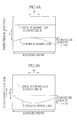
- a "curvature amount" of the scanning line represents projection length when the scanning line to be drawn is projected in the sub-scanning direction S as shown in FIG.4, and the curvature amount is defined as positive if the curvature of the scanning line is convex to the positive direction of the sub-scanning direction S (see FIG.4A), while it is defined as negative if the curvature is concave to the positive direction of the sub-scanning direction S (see FIG.4B).
- the scanning line is recorded on the well-known size of the recording paper (e.g. L-size, 2L-size, and KG-size).
- the maximum size of the recording paper capable of being recorded by the light scanning device 2 is used.
- Ki Ki is a constant.
- the rotating direction around the central axis extending in the main scanning correspondence direction CM of each f ⁇ lens and the ratio of absolute value of each inclination angle are determined so that absolute value of the summation of the curvature amount of all f ⁇ lenses "
- " may be determined so that absolute value of the summation of the curvature amount "
- K1 is calculated by measuring the curvature amount ⁇ 1 in the case where the first f ⁇ lens 17 is inclined at the predetermined inclination angle A1.
- the rotating directions of the f ⁇ lenses 17 and 18 are respectively reversed when the following condition is satisfied: K1 ⁇ K2 > 0, while the rotating directions are oriented in the same direction when the following condition is satisfied: K1 ⁇ K2 ⁇ 0 .
- K1 ⁇ K2 is calculated by measuring the curvature amount ⁇ 1 in the case where the first f ⁇ lens 17 is inclined at the predetermined inclination angle A1.
- the rotating directions of the f ⁇ lenses 17 and 18 are respectively reversed when the following condition is satisfied
- the ratio of the absolute value of the inclination angles ⁇ 1 and ⁇ 2 is an inverse ratio of the absolute value of the curvature amount ⁇ 1 and ⁇ 2, and represented by the following condition:
- " may be used. Thereby, each absolute value of ⁇ 1 and ⁇ 2 becomes similar.
- the positive and negative signs of the curvature amounts ⁇ 1, ⁇ 2 are respectively reversed by disposing each f ⁇ lens 17, 18 in accordance with the inclination angles ⁇ 1, ⁇ 2 determined based on the first condition, so that the amount of ⁇ 1, ⁇ 2 becomes about the same.
- ⁇ 1 and ⁇ 2 offset each other, so that it is considered that the sum of the curvature amount becomes approximately zero.
- each of the f ⁇ lenses 17, 18 is preferably arranged correctly; however, since arrangement error occurs when arranging these lenses in fact, an allowable error in the sum of the curvature amount is determined, so that each f ⁇ lens 17, 18 may be arranged by the inclination angle satisfying the condition:
- the width of the scanning line is about 0. 05 - 0.1 mm.
- the inclination angle preferably satisfies the condition:
- the scanning lens is constituted of two lens units: first and second f ⁇ lenses 17, 18; however, even if the scanning lens is constituted of three or more lens units, the rotating direction of each lens unit and the ratio of the absolute value of the inclination angle of each lens unit are calculated to satisfy the first condition.
- the scanning lens is constituted of three lens units. In this case, as a matter of convenience, specific numeric values are used.
- the scanning lens is constituted of a first f ⁇ lens, a second f ⁇ lens, and a third f ⁇ lens.
- the curvature amounts are measured by inclining each of these f ⁇ lenses, one at a time, at the predetermined angle.
- the rotating directions of the first and second f ⁇ lenses are reversed to the rotating direction of the third f ⁇ lens, and the ratio of the absolute value of the inclination angle of each f ⁇ lens is determined as follows:
- 1:1:1.
- the curvature amounts ⁇ 1, ⁇ 2, and ⁇ 3 are +1 ⁇ m, +2 ⁇ m, and -3 ⁇ m respectively, so that the summation of the curvature amount becomes zero.
- the rotating directions of the first and third f ⁇ lenses are reversed to the rotating direction of the second f ⁇ lens, and the ratio of the absolute value of the inclination angle of each f ⁇ lens is determined to satisfy the following equation:
- 1:2:1.
- ⁇ 1, ⁇ 2, and ⁇ 3 are +1 ⁇ m, -4 ⁇ m, and +3 ⁇ m, so that the summation of the curvature amount is zero. Since there are plural combinations in the rotating direction of each f ⁇ lens and the ratio of the absolute value of each inclination angle, the appropriate pattern can be selected.
- each f ⁇ lens may be arranged in accordance with the inclination angle satisfying the following condition:
- the second condition which the inclination angle ⁇ 1 should fulfill is expressed by the following mathematical expression (9) (see FIG.7).
- the inclination angle ⁇ 1 is determined within the mathematical expression (9): ⁇
- > ⁇ 0 1 + ( 4 ⁇ Q ⁇ ⁇ ⁇ 0 2 ) 2 However , - ( t 0 2 - ⁇ 0 ) ⁇ r 0 ⁇ t 0 2 - ⁇ 0 Q ⁇ ⁇ 0 - ⁇ 1 cos ⁇ 1 + r 0 tan ⁇ 1 + 1 2
- the light beam entered the polygon mirror 5 is reflected in parallel with the center axis of the first f ⁇ lens 17.
- out of the light beam which satisfies a condition that the incident angle to the polygon mirror 5 is closet to the average value of the incident angles of all light beams, is assumed to be reflected in parallel with the axis of the first f ⁇ lens 17.
- the middle light beam is assumed to be reflected in parallel with the axis of the first f ⁇ lens 17.
- the even numbers of the light beams are separated at a constant interval in angle to enter the polygon mirror 5
- a hypothetical light beam in the middle between two light beams, which is closet to the average value of the incident angles of all light beams, is assumed to be reflected in parallel with the axis of the first f ⁇ lens 17.
- the reference light beam is referred to as a reference-light beam.
- the light beam reflected in parallel with the axis of the first f ⁇ lens 17 is represented as L1.
- the reference-light beam corresponds to the light beam L1.
- FIG.7 shows the deflection of the light beamL1 on the reflective surface 5a and the state that the first entering light beam L1 is entered/reflected to the first f ⁇ lens 17.
- a zx flat surface is a scanned surface by the light beam L1.
- a z direction is the main scanning correspondence direction CM, and a y direction is the sub-scanning correspondence direction CS.
- the width in the sub-scanning correspondence direction CS of the reflective surface 5a is t0.
- a beam waist diameter of the light beam L1 (13.5% intensity diameter) near the reflection point R0 is ⁇ 0.
- the effective area of the Gaussian beam entering the polygon mirror 5 is assumed to be no more than twice as large as the diameter of the Gaussian beam (area of 13.5% intensity to the peak intensity).
- the condition of the position of the reflection point is determined so that the effective area does not deviate from a reflecting area of the reflective surface 5a.
- the condition of r0 satisfies the following condition (11): - ( t 0 2 - ⁇ 0 ) ⁇ r 0 ⁇ t 0 2 - ⁇ 0
- the light beam L1 reflected on the reflective surface 5a passes through the reflection point R0.
- the inclination angle of the first f ⁇ lens 17 is represented as ⁇ 1.
- the distance from the reflection point R0 to the flat surface perpendicular to the main scanning plane is represented as ⁇ 0.
- the flat surface includes the center axis 24 of the first f ⁇ lens 17.
- the distance from the center axis 24 to the entering surface 22a of the first f ⁇ lens 17 is represented as ⁇ 1.
- the wavelength of the light beam from the light source (the longest wavelength in a multi laser optical system) is represented as ⁇ .
- a point at the intersection of the straight lines L1 and L2, namely a point satisfying the equations (12) and (13) represents the reflection point R1 of the light beam L1 on the light entering surface 17a of the first f ⁇ lens 17.
- Q ⁇ satisfies the following equation (20):
- the condition that reflective surface 5a of the polygon mirror 5 is not included within the beam effective area at the point B of the light beam L3, namely the condition that the line segment AB is larger than twice the beam radius 6 at the point B is represented by the mathematical expression (9) based on the expressions (11), (16), (20), and (21).
- each light beam reflected on the light entering surface 17a of the first f ⁇ lens 17 advances to the ineffective area where each light beam does not reach the recording paper 7 without entering the reflective surface 5a of the polygon mirror 5 as shown in FIG.9.
- the inclination angle ⁇ 1 is determined so as to satisfy the mathematical expression (22) as follows: where ⁇ is the wave length of the longest light beam; ⁇ 0 is the beam waist diameter of the light beam L1 having wave length ⁇ near the reflective surface 5a of the polygon mirror 5; ⁇ 0 is distance from the reflection point R0 of the light beam L1 on the reflective surface 5a to the flat surface perpendicular to the main scanning plane, and the flat surface includes the center axis 24 of the first f ⁇ lens 17; ⁇ 1 is distance from the center axis 24 to the light entering surface 17a of the first f ⁇ lens 17; r0 is distance from the flat surface parallel to the main scanning plane to the reflection point R0, and the flat surface includes the center axis 24; t1 is width in the sub-scanning correspondence direction CS of the reflective surface 5a; and t2 is width of the light entering surface 17a in the sub
- the effective area of the Gaussian beam entering the polygon mirror 5 is assumed to be twice as large as the diameter of the Gaussian beam (area of 13.5% intensity to the peak intensity).
- the condition of the position of the reflection point is determined so that the effective area does not deviate from a reflecting area of the reflective surface 5a.
- the condition of r0 satisfies the following condition (25): - ( t 1 2 - ⁇ 0 ) ⁇ r 0 ⁇ t 1 2 - ⁇ 0
- the width in the sub-scanning correspondence direction CS of the reflective surface 5a of the polygon mirror 5 is represented as t1.
- the width in the sub-scanning correspondence direction CS of the light entering surface 17a of the first f ⁇ lens 17 is represented as t2. ⁇ 0, ⁇ 1, and ⁇ are similar to the case where the formula 9 is derived.
- the point at the intersection of the straight lines L1 and L2, namely a point satisfying the equations (24) and (26) represents the reflection point R1 on the light entering surface 17a of the first f ⁇ lens 17 (straight line L2).
- the coordinate U in FIG.10 is calculated.
- the coordinate U0 is assumed to rotate by - ⁇ 1 around the coordinate C.
- the length of the line segment ST corresponds to the distance between the point S and a straight line 5 which is perpendicular to the straight line L4 and passes through the point U.
- the straight line L4 is the re-reflecting light on the polygon mirror 5.
- the point U is an end surface of the light entering surface 17a of the first f ⁇ lens 17.
- the condition that light entering surface 17a of the first f ⁇ lens 17 is not included within the beam effective area at the point T of the light beam L4, namely the condition that the line segment TU is larger than twice the beam radius 6 at the point T is represented by the mathematical expression (22) based on the expressions (25), (33), (35), (37), and (39).
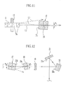
- each light beam reflected on the light entering surface 17a of the first f ⁇ lens 17 advances to the ineffective area without entering the light entering surface 17a again after re-reflecting on the reflective surface 5a of the polygon mirror 5 as shown in FIG.11.
- the inclination angle ⁇ 1 is determined within the range satisfying the second condition as above, so that it is possible to prevent the ghost caused by the multiple reflections occurring between the polygon mirror 5 and the first f ⁇ lens 17.
- the ranges of the inclination angles ⁇ 1 and ⁇ 2 are determined such that the effective area of the multi-reflecting light beam between the first f ⁇ lens 17 and the second f ⁇ lens 18 (twice the beam diameter area of 13.5% intensity) does not enter the reflective surface 20a of the cylindrical mirror 20 or the reflective surface 21a of the flat mirror 21.
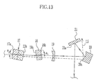
- the effective area of the multi-reflecting light beam between the first f ⁇ lens 17 and the second f ⁇ lens 18 advances to the ineffective area without entering the reflective surface 20a of the cylindrical mirror 20 as shown in FIG.12 or the reflective surface 21a of the flat mirror 21 as shown in FIG.13. Thereby, it is possible to prevent the ghost occurring due to the multi-reflecting light beam between the first f ⁇ lens 17 and the second f ⁇ lens 18.
- the inclination angles ⁇ 1 and ⁇ 2 are determined so as to satisfy the first, second, and third conditions, so that it is possible to prevent the ghost occurring due to the multi-reflecting light between the polygon mirror 5 and the first f ⁇ lens 17 and between the first f ⁇ lens 17 and the second f ⁇ lens 18.
- the curvature amount of the scanning line 8 can be kept to the minimum.
- new optical element is not required by determining the inclination angles ⁇ 1 and ⁇ 2.
- the inclination angles ⁇ 1 and ⁇ 2 are determined so as to satisfy the first, second, and third conditions.
- the inclination angles ⁇ 1 and ⁇ 2 may be determined so as to satisfy only the first and second conditions, or only the first and third conditions.
- the scanning line 8 is recorded on the recording paper 7 fed in the advancing direction
- the scanning line may be recorded on a photoreceptor rotating around a predetermined axis instead of the recording paper 7.
- the light scanning device 2 can be used in a laser printer and the like in addition to the photo-printer.
- reflecting light from a manuscript is read out by a line sensor or the like after putting the manuscript on a scanned surface, so that the present invention can be applied to an image reader.
Landscapes
- Physics & Mathematics (AREA)
- General Physics & Mathematics (AREA)
- Optics & Photonics (AREA)
- Mechanical Optical Scanning Systems (AREA)
- Laser Beam Printer (AREA)
- Facsimile Scanning Arrangements (AREA)
- Lenses (AREA)
Abstract
Description
- The present invention relates to a light scanning device used in an image reader and an image recording apparatus.
- A photo-printer, a laser printer, and the like are provided with a light scanning device for converging a light beam emitted from a light source on a scanned surface as a light spot and scanning the light spot on the scanned surface. The light scanning device is provided with a polygon mirror for scanning the light beam, and scanning lenses for focusing the light beam. However, there is a problem that a printing trouble so-called "ghost" occurs on the scanned surface due to multiple reflections of a part of the light beam between the optical members.
- Japanese Patent Laid-Open Publications No. 9-33842 and No. 5-346553 propose to remove reflection components by rotating the scanning lens in the main scanning direction, so that the ghost caused by the multiple reflections is prevented.
- In addition, Japanese Patent Laid-Open Publication No. 9-274134 proposes to prevent the ghost caused by the reflection on the flat covering plate by tilting the flat covering plate, which constitutes a part of the housing for sealing the polygon mirror.
- However, in Japanese Patent Laid-Open Publications No. 9-33842 and No. 5-346553, there is another problem that the scanning line is curved in a sub-scanning direction by tilting the scanning lens. This curvature of the scanning line, so-called "bowing" deteriorates the image quality. Although Japanese Patent Laid-Open Publication No. 9-274134 is provided with an extra flat plate for correcting the curvature of the scanning line caused by tilting the flat covering plate, the scanning device becomes complicated and the manufacturing cost is raised.
- A primary object of the present invention is to provide a light scanning device capable of preventing ghost with a simple structure.
- Another object of the present invention is to provide a light scanning device capable of keeping curvature of a scanning line generated in a sub-scanning direction to minimum.
- In order to achieve the above and other objects, a light scanning device of the present invention includes a scanning lens group. The scanning lens group has (n) lens units (n is a natural number of ≥ 2). The lens units are arranged so that optical axes thereof are inclined to a main scanning plane. The inclination angle of each lens unit should be determined to satisfy the following condition:

where αi is the inclination angle of an i-th lens unit (i is from 1 to n) from a deflector, and a change rate Ki when only the i-th lens unit is inclined at a minute angle Ai is defined as Ki=Δi/Ai where a curvature amount on a scanned surface is represented as Δi. - In a preferred embodiment of the present invention, the light scanning device has at least one optical member for reflecting a light beam from the scanning lens group to the scanned surface. The inclination angle of each lens unit is determined such that the beam reflected plural times between the lens units does not enter the optical member. The inclination angle α1 of a first lens unit, which is the closest lens unit to the deflector, satisfies the following mathematical expression (5):

where λ is a wave length of the longest light beam; ω0 is a beam waist diameter of the light beam having wave length λ near a reflective surface of the deflector; ξ0 is distance from a reflection point of the light beam on the reflective surface of the deflector to a flat surface perpendicular to amain scanning plane, and the flat surface includes a center axis of the first lens unit; ξ1 is distance from the center axis of the first lens unit to the light entering surface of the first lens unit; r0 is distance from a flat surface parallel to the main scanning plane to the reflection point of the light beam on the reflective surface of the deflector, and the flat surface includes the center axis of the first lens unit; and t0 is width in a sub-scanning correspondence direction of the reflective surface of the deflector. - The inclination angle α1 satisfies the following mathematical expression (6):

- In a preferred embodiment of the present invention, the lens unit has a first fθ lens and a second fθ lens disposed one by one from the deflector.
- According to the light scanning device of the present invention, both the ghost and the curvature of the scanning line in the sub-scanning direction can be kept to the minimum with a simple structure.
- The above and other subjects and advantages of the present invention will become apparent from the following detailed description of the preferred embodiments when read in association with the accompanying drawings, which are given by way of illustration only and thus are not limiting the present invention. In the drawings, like reference numerals designate like or corresponding parts throughout the several views, and wherein:
- FIG.1 is a schematic perspective view of a light scanning device of the present invention;
- FIG.2 is a side view of the light scanning device;
- FIG.3 is a side view of a cylindrical mirror;
- FIGS.4A and 4B are explanatory views of a curvature amount of a scanning line;
- FIGS.5A and 5B are graphs showing relation between an inclination angle and the curvature amount of the scanning line;
- FIG.6 is a plan view of a polygon mirror and a first fθ lens;
- FIG. 7 is a cross-sectional side view of the polygon mirror and the first fθ lens;
- FIG.8 is a graph showing intensity distribution of a light beam;
- FIG.9 is a view for explaining the state where multiple reflections between the polygon mirror and the first fθ lens are transmitted to an ineffective area;
- FIG. 10 is cross-sectional side view of the polygon mirror and the first fθ lens;
- FIG.11 is a view for explaining the state where multiple reflections between the polygon mirror and the first fθ lens are transmitted to the ineffective area;
- FIG.12 is a view for explaining the state where multiple reflections between the first fθ lens and a second fθ lens are transmitted to the ineffective area; and
- FIG.13 is a view for explaining the state where multiple reflections between the first fθ lens and the second fθ lens are transmitted to the ineffective area.
- As shown in FIG.1, a
light scanning device 2 is constituted oflight sources optical system 4, apolygon mirror 5, and a scanningoptical system 6. Laser is used as thelight sources optical system 4 irradiates each light beam from thelight sources polygon mirror 5. The scanningoptical system 6 converges each light beam modulated by thepolygon mirror 5 on aphotosensitive recording paper 7 set on a scanned surface as a light spot. One line of a color image is recorded on therecording paper 7 as a scanning line 8 by scanning the light spot in a main scanning direction M on therecording paper 7. - Hereinafter, a flat surface which is perpendicular to a
rotation shaft 13 of thepolygon mirror 5 and formed by deflection of the light beam is referred to as a main scanning plane. Meanwhile, a direction where the light beam is deflected by thepolygon mirror 5 is referred to as a main scanning correspondence direction CM corresponding to the main scanning direction M of therecording paper 7. Moreover, a direction perpendicular to the main scanning correspondence direction CM is referred to as a sub-scanning correspondence direction CS corresponding to the sub-scanning direction S of therecording paper 7. - The light source
optical system 4 is a multibeam optical system and constituted ofcollimator lenses cylindrical lenses collimator lenses light sources cylindrical lenses collimator lenses - The
polygon mirror 5 having a polygonal prism shape is a mirror each side surface of which is areflective surface 5a, and rotates around therotation shaft 13 at a constant speed. The light beam entered thereflective surface 5a is deflected by thepolygon mirror 5, and then advances to the scanningoptical system 6. Thepolygon mirror 5 is in an interlocked state when a cover (not shown) for thelight scanning device 2 is opened, and then stops rotating. Meanwhile, although thepolygon mirror 5 is in a standby state to rotate at low speed when the light beam is not emitted from the light source 3 with the cover closed, thepolygon mirror 5 rotates at high speed when scanning the light beam from the light source 3. - The scanning
optical system 6 is constituted of afirst fθ lens 17, asecond fθ lens 18, acylindrical lens 19, acylindrical mirror 20, and aflat mirror 21. Thefirst fθ lens 17 and thesecond fθ lens 18 are lens units, which mean a single lens or a lens group in which plural lenses are integrated. - The
first fθ lens 17 is constituted of afirst lens 22 and asecond lens 23. Thefirst lens 22 has a concavecylindrical surface 22a in the light entering side and aflat surface 22b in the light exiting side. The concavecylindrical surface 22a has power only in the main scanning correspondence direction CM. Theflat surface 22b does not have power in any direction. Thesecond lens 23 has aflat surface 23a in the light entering side and a convexcylindrical surface 23b in the light exiting side. The convexcylindrical surface 23b has power only in the main scanning correspondence direction CM. The first andsecond lenses flat surfaces cylindrical surface 22a is alight entering surface 17a of thefirst fθ lens 17. Thesecond fθ lens 18 has aflat surface 18a in the light entering side and a convexcylindrical surface 18b in the light exiting side. The convexcylindrical surface 18b has power only in the main scanning correspondence direction CM. - As shown in FIG.2, the
first fθ lens 17 is arranged to have an inclination angle α1 to the main scanning plane centering around acenter axis line 24 extending in the main scanning correspondence direction CM. Thesecond fθ lens 18 is arranged to have an inclination angle α2 to the main scanning plane centering around acenter axis line 25 extending in the main scanning correspondence direction CM. The inclination angles α1 and α2 are determined by the after-mentioned conditions. - Aberrations of the first and
second fθ lenses polygon mirror 5 is scanned on therecording paper 7 at a constant speed in the main scanning direction M. - The
cylindrical lens 19 has a concavecylindrical surface 19a in the light entering side and aflat surface 19b in the light exiting side. The concavecylindrical surface 19a has power only in the sub-scanning correspondence direction CS. Thecylindrical mirror 20 has areflective surface 20a which is a concave cylindrical surface having power only in the sub-scanning correspondence direction CS. The light beam exited from thesecond fθ lens 18 is converged in the sub-scanning correspondence direction CS through thecylindrical lens 19 and thecylindrical mirror 20. If the verticality of thereflective surface 5a is varied, the deflection in the sub-scanning correspondence direction CS of the light beam can be corrected. Thereby, the plane tilt of thepolygon mirror 5 is corrected so that the irregularity in a line space between the scanning lines 8 on therecording paper 7 can be prevented. - As shown in FIG.3, the
cylindrical mirror 20 is held by amirror retainer 27 having an L-shaped cross-sectional surface. Abottom surface 20b and arear surface 20c of thecylindrical mirror 20 are pressed to contact aninner surface 27a of themirror retainer 27 by aleaf spring 28 provided in both ends in the main scanning correspondence direction CM of themirror retainer 27. Thereby, thecylindrical mirror 20 is surely fixed to themirror retainer 27. - The
flat mirror 21 shown in FIG.1 reflects the light beam from thecylindrical mirror 20 on areflective surface 21a to irradiate the light beam onto therecording paper 7. Therecording paper 7 is advanced along the sub-scanning direction S by a feeding device (not shown). The image is recorded on therecording paper 7 by scanning and exposing the light beam in the main scanning direction M as therecording paper 7 is advanced. - The inclination angles α1 and α2 to the main scanning plane of the first and
second fθ lenses light scanning device 2 is used. - First, the generalized first condition is shown. The fθ lenses are numbered as i = 1, 2, ... from the fθ lens closest to the
polygon mirror 5, and the inclination angle of the i-th fθ lens is determined to αi. When only the i-th fθ lens is inclined at αi, the curvature amount in the sub-scanning direction S of the scanning line 8 to be drawn on therecording paper 7 is represented as δi. If αi is small, δi is changed approximately linearly to αi, and can be approximated as the following equation: δi = Ki αi. The change rate Ki is a constant. Ki can be calculated by measuring the curvature amount (Δi) in the case where the i-th fθ lens has the predetermined inclination angle (Ai). Ki satisfies the following equation: Ki = Δi / Ai. With respect to αi, a clockwise direction is assumed positive, while a counter clockwise direction is assumed negative in FIG 2. - In the first condition, the rotating direction around the central axis extending in the main scanning correspondence direction CM of each fθ lens and the ratio of absolute value of each inclination angle are determined so that absolute value of the summation of the curvature amount of all fθ lenses "|Σδi|" becomes the minimum.
- When the first condition is applied to the present embodiment, the rotating direction around the
central axes second fθ lenses - As shown in FIG.5A, K1 is calculated by measuring the curvature amount Δ1 in the case where the
first fθ lens 17 is inclined at the predetermined inclination angle A1. As shown in FIG.5B, a change rate K2 is calculated by measuring the curvature amount Δ2 in the case where thesecond fθ lens 18 is inclined at the predetermined inclination angle A2 (= A1). The rotating directions of thefθ lenses - The ratio of the absolute value of the inclination angles α1 and α2 is an inverse ratio of the absolute value of the curvature amount Δ1 and Δ2, and represented by the following condition: |α1|:|α2| = |1/Δ1| : |1/Δ2|. Instead of the inverse ratio of the absolute value of Δ1 and Δ2, an inverse ratio of the absolute value of the change rates K1 and K2 "|α1|:|α2| = |1/K1| : |1/K2|" may be used. Thereby, each absolute value of δ1 and δ2 becomes similar.
- As above-mentioned, the positive and negative signs of the curvature amounts δ1, δ2 are respectively reversed by disposing each
fθ lens fθ lenses fθ lens recording paper 7, the inclination angle preferably satisfies the condition: |K1 α1 + K2 α2| ≤ 0.1 mm, more preferably, |K1 α1 + K2 α2| ≤ 0.05mm. - In the above embodiment, the scanning lens is constituted of two lens units: first and
second fθ lenses - The scanning lens is constituted of a first fθ lens, a second fθ lens, and a third fθ lens. The curvature amounts are measured by inclining each of these fθ lenses, one at a time, at the predetermined angle. The curvature amounts are assumed to be measured as follows: when A1 = +1° , Δ1 = +1 µm; when A2 = +1°, Δ2 = +2 µm; and when A3 = +1° , Δ3 = +3 µm.
- In this case, the rotating directions of the first and second fθ lenses are reversed to the rotating direction of the third fθ lens, and the ratio of the absolute value of the inclination angle of each fθ lens is determined as follows: |α1|:|α2|:|α3|=1:1:1. Thereby, the curvature amounts δ1, δ2, and δ3 are +1 µm, +2 µm, and -3 µm respectively, so that the summation of the curvature amount becomes zero.
- Instead of the above combination, the rotating directions of the first and third fθ lenses are reversed to the rotating direction of the second fθ lens, and the ratio of the absolute value of the inclination angle of each fθ lens is determined to satisfy the following equation: |α1|:|α2|:|α3| = 1:2:1. Thereby, δ1, δ2, and δ3 are +1 µm, -4 µm, and +3 µm, so that the summation of the curvature amount is zero. Since there are plural combinations in the rotating direction of each fθ lens and the ratio of the absolute value of each inclination angle, the appropriate pattern can be selected. The allowable error in the sum of the curvature amount is determined, so that each fθ lens may be arranged in accordance with the inclination angle satisfying the following condition: |Σδi| ≤ 0.2 mm, particularly |Σδi| ≤ 0.1 mm, especially |Σδi| ≤ 0.05 mm.
- Next, the second condition is explained. The second condition which the inclination angle α1 should fulfill is expressed by the following mathematical expression (9) (see FIG.7). The inclination angle α1 is determined within the mathematical expression (9):

- Next, a derivation process of the mathematical expression (9) is shown. Here, the light beam entered the
polygon mirror 5 is reflected in parallel with the center axis of thefirst fθ lens 17. When the plural light beams enter thepolygon mirror 5 without combining, out of the light beam, which satisfies a condition that the incident angle to thepolygon mirror 5 is closet to the average value of the incident angles of all light beams, is assumed to be reflected in parallel with the axis of thefirst fθ lens 17. Especially, as shown in FIG.6, when the odd numbers of light beams are separated with one another at a constant interval in angle to enter thepolygon mirror 5, the middle light beam is assumed to be reflected in parallel with the axis of thefirst fθ lens 17. Meanwhile, the even numbers of the light beams are separated at a constant interval in angle to enter thepolygon mirror 5, a hypothetical light beam in the middle between two light beams, which is closet to the average value of the incident angles of all light beams, is assumed to be reflected in parallel with the axis of thefirst fθ lens 17. Hereinafter, when the light beams specified as above, namely plural light beams enter thepolygon mirror 5, the reference light beam is referred to as a reference-light beam. - The light beam reflected in parallel with the axis of the
first fθ lens 17 is represented as L1. When the plural light beams are entered thepolygon mirror 5 without combining, the reference-light beam corresponds to the light beam L1. FIG.7 shows the deflection of the light beamL1 on thereflective surface 5a and the state that the first entering light beam L1 is entered/reflected to thefirst fθ lens 17. A zx flat surface is a scanned surface by the light beam L1. A z direction is the main scanning correspondence direction CM, and a y direction is the sub-scanning correspondence direction CS. - The reflection point R0 of the light beam L1 on the
reflective surface 5a is represented by the following equation (10):
- The width in the sub-scanning correspondence direction CS of the
reflective surface 5a is t0. A beam waist diameter of the light beam L1 (13.5% intensity diameter) near the reflection point R0 is ω0. As shown in FIG.8, the effective area of the Gaussian beam entering thepolygon mirror 5 is assumed to be no more than twice as large as the diameter of the Gaussian beam (area of 13.5% intensity to the peak intensity). The condition of the position of the reflection point is determined so that the effective area does not deviate from a reflecting area of thereflective surface 5a. Thereby, the condition of r0 satisfies the following condition (11):
- The light beam L1 reflected on the
reflective surface 5a passes through the reflection point R0. The reflected light beam L1 is a straight line in parallel with x-axis to satisfy the following equation (12):
- The inclination angle of the
first fθ lens 17 is represented as α1. The distance from the reflection point R0 to the flat surface perpendicular to the main scanning plane is represented as ξ0. The flat surface includes thecenter axis 24 of thefirst fθ lens 17. The distance from thecenter axis 24 to the enteringsurface 22a of thefirst fθ lens 17 is represented as ξ1. The wavelength of the light beam from the light source (the longest wavelength in a multi laser optical system) is represented as λ. - A straight line L2 representing the
light entering surface 17a of thefirst fθ lens 17 satisfies the following equation (13):
- A point at the intersection of the straight lines L1 and L2, namely a point satisfying the equations (12) and (13) represents the reflection point R1 of the light beam L1 on the
light entering surface 17a of thefirst fθ lens 17. The reflection point R1 satisfies the following equation (14):
- A straight line L3 satisfies the following equation (15) :

- The distance between the straight line L3 and a point A, which is an end surface of the
reflection point 5a (the length of line segment AB) is obtained by the following equation (16):
- With respect to a beam profile at a point B, when a beam radius of 13.5% intensity is assumed to be 6, the effective area will be 26, so that it is necessary that the length of the line segment AB is larger than 26 in order to prevent the occurrence of the ghost light.
- Transmission distance of the main light beam from the point R0 to the point B is calculated to obtain the beam radius δ at the point B. The distance from the point R0 to the point R1 satisfies the following equation (17) based on the equation (14) :

- The line segment AB satisfies the following equation (18) :

- The distance from the point R1 to the point B satisfies the following equation (19):

- When the transmission distance of the main light beam from the point R0 to the point B is represented as Qα, Qα satisfies the following equation (20):
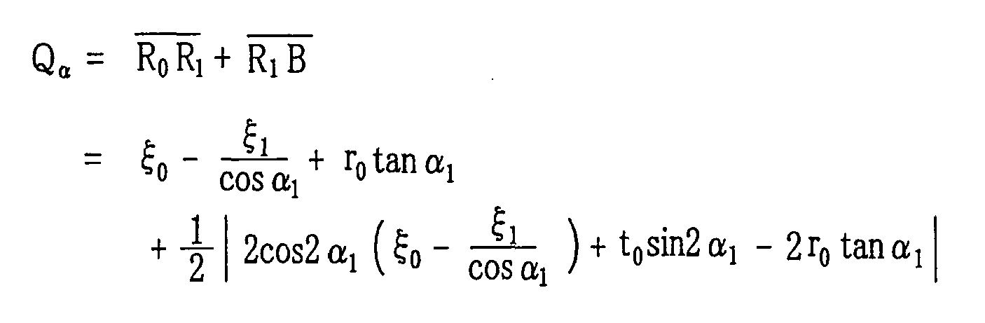
- When the formula showing the relation between the beam waist diameter of the Gaussian beam and the transmission is used, the beam radius δ (13.5% intensity) at the point B satisfies the following equation (21):

- The condition that
reflective surface 5a of thepolygon mirror 5 is not included within the beam effective area at the point B of the light beam L3, namely the condition that the line segment AB is larger than twice thebeam radius 6 at the point B is represented by the mathematical expression (9) based on the expressions (11), (16), (20), and (21). - If the inclination angle α1 is set within the range satisfying the mathematical expression (9), each light beam reflected on the
light entering surface 17a of thefirst fθ lens 17 advances to the ineffective area where each light beam does not reach therecording paper 7 without entering thereflective surface 5a of thepolygon mirror 5 as shown in FIG.9. - In the second condition, the following mathematical expression (22) (see FIG.10) may be used instead of the mathematical expression (9). In this case, the inclination angle α1 is determined so as to satisfy the mathematical expression (22) as follows:

reflective surface 5a of thepolygon mirror 5; ξ0 is distance from the reflection point R0 of the light beam L1 on thereflective surface 5a to the flat surface perpendicular to the main scanning plane, and the flat surface includes thecenter axis 24 of thefirst fθ lens 17; ξ1 is distance from thecenter axis 24 to thelight entering surface 17a of thefirst fθ lens 17; r0 is distance from the flat surface parallel to the main scanning plane to the reflection point R0, and the flat surface includes thecenter axis 24; t1 is width in the sub-scanning correspondence direction CS of thereflective surface 5a; and t2 is width of thelight entering surface 17a in the sub-scanning correspondence direction CS. - Hereinafter, a derivation process of the mathematical expression (22) is shown with reference to FIG.10. When the light beam reflected on the
polygon mirror 5 is L1, and the light beam which is a component reflected on thelight entering surface 17a (straight line L2) is L3, a light beam L4 which is a component reflected again at a point S of thereflective surface 5a is considered. A closest distance between the straight line L4 and thefirst fθ lens 17 corresponds to the length of line segment TU in FIG.10. When the line segment TU is larger than the effective area (assumed to be twice the beam diameter area of 13.5% intensity), the light beam L4 does not enter thefirst fθ lens 17 again. The mathematical expression (22) is obtained by a similar procedure to the mathematical expression (9). - The reflection point R0 on the
reflective surface 5a of thepolygon mirror 5 is represented by the following equation (23):
- The light beam L1 is a straight line parallel to the x-axis and satisfies the following equation (24):

- The effective area of the Gaussian beam entering the
polygon mirror 5 is assumed to be twice as large as the diameter of the Gaussian beam (area of 13.5% intensity to the peak intensity). The condition of the position of the reflection point is determined so that the effective area does not deviate from a reflecting area of thereflective surface 5a. Thereby, the condition of r0 satisfies the following condition (25):
- The width in the sub-scanning correspondence direction CS of the
reflective surface 5a of thepolygon mirror 5 is represented as t1. The width in the sub-scanning correspondence direction CS of thelight entering surface 17a of thefirst fθ lens 17 is represented as t2. ξ0, ξ1, and λ are similar to the case where the formula 9 is derived. - The straight line L2 satisfies the following equation (26):

- The point at the intersection of the straight lines L1 and L2, namely a point satisfying the equations (24) and (26) represents the reflection point R1 on the
light entering surface 17a of the first fθ lens 17 (straight line L2). The reflection point R1 satisfies the following equation (27):
- The straight line L3 satisfies the following equation (28) :

- The coordinate of a re-entering point S of the light beam L3 which is a re-entering light to the
polygon mirror 5 satisfies the following equation (29) based on the y-coordinate in the equation (28):
- Here, the coordinate U in FIG.10 is calculated. The coordinate U0 is assumed to rotate by - α1 around the coordinate C. When the origin of the coordinate is represented as O, the coordinate U satisfies the following equations (30) and (31):


- The
straight line 4 satisfies the following equation (32) :
- The distance between the straight line L3 and the point U is obtained by the equations (31) and (32) (length of the line segment TU), and then these equations are deformed as follows:

- The beam transmission distance from the point R0 to the point T satisfies the following equation (34):

- The first two terms in the equation (34) are shown by the following equation (35) based on the equation (27) and the right triangle R0 R1 S in FIG.10:

- The length of the line segment ST corresponds to the distance between the point S and a
straight line 5 which is perpendicular to the straight line L4 and passes through the point U. The straight line L4 is the re-reflecting light on thepolygon mirror 5. The point U is an end surface of thelight entering surface 17a of thefirst fθ lens 17. The straight line L5 satisfies the following equation (36):
- The length of the line segment ST satisfies the following equation (37):

- Beam transmission distance R0-T from the point R0 to the point T satisfies the following equation (38) based on the equations (34), (35), and (37):

- When the formula showing the relation between the beam waist diameter of the Gaussian beam and the transmission is used, the beam radius δ (13.5% intensity) at the point T satisfies the following mathematical expression (39):

- As above-mentioned, the condition that light entering
surface 17a of thefirst fθ lens 17 is not included within the beam effective area at the point T of the light beam L4, namely the condition that the line segment TU is larger than twice thebeam radius 6 at the point T is represented by the mathematical expression (22) based on the expressions (25), (33), (35), (37), and (39). - If the inclination angle α1 is set within the range satisfying the mathematical expression (22), each light beam reflected on the
light entering surface 17a of thefirst fθ lens 17 advances to the ineffective area without entering thelight entering surface 17a again after re-reflecting on thereflective surface 5a of thepolygon mirror 5 as shown in FIG.11. - The inclination angle α1 is determined within the range satisfying the second condition as above, so that it is possible to prevent the ghost caused by the multiple reflections occurring between the
polygon mirror 5 and thefirst fθ lens 17. - In the third condition, the ranges of the inclination angles α1 and α2 are determined such that the effective area of the multi-reflecting light beam between the
first fθ lens 17 and the second fθ lens 18 (twice the beam diameter area of 13.5% intensity) does not enter thereflective surface 20a of thecylindrical mirror 20 or thereflective surface 21a of theflat mirror 21. - When the inclination angles α1 and α2 satisfy the third condition, the effective area of the multi-reflecting light beam between the
first fθ lens 17 and thesecond fθ lens 18 advances to the ineffective area without entering thereflective surface 20a of thecylindrical mirror 20 as shown in FIG.12 or thereflective surface 21a of theflat mirror 21 as shown in FIG.13. Thereby, it is possible to prevent the ghost occurring due to the multi-reflecting light beam between thefirst fθ lens 17 and thesecond fθ lens 18. - The inclination angles α1 and α2 are determined so as to satisfy the first, second, and third conditions, so that it is possible to prevent the ghost occurring due to the multi-reflecting light between the
polygon mirror 5 and thefirst fθ lens 17 and between thefirst fθ lens 17 and thesecond fθ lens 18. In addition, the curvature amount of the scanning line 8 can be kept to the minimum. Moreover, new optical element is not required by determining the inclination angles α1 and α2. - In the above embodiment, the inclination angles α1 and α2 are determined so as to satisfy the first, second, and third conditions. However, the inclination angles α1 and α2 may be determined so as to satisfy only the first and second conditions, or only the first and third conditions.
- In the above embodiment, although the scanning line 8 is recorded on the
recording paper 7 fed in the advancing direction, the scanning line may be recorded on a photoreceptor rotating around a predetermined axis instead of therecording paper 7. Accordingly, thelight scanning device 2 can be used in a laser printer and the like in addition to the photo-printer. Moreover, reflecting light from a manuscript is read out by a line sensor or the like after putting the manuscript on a scanned surface, so that the present invention can be applied to an image reader. - Although the present invention has been fully described by the way of the preferred embodiments thereof with reference to the accompanying drawings, various changes and modifications will be apparent to those having skill in this field. Therefore, unless otherwise these changes and modifications depart from the scope of the present invention, they should be construed as included therein.
Claims (11)
- A light scanning device (2) for focusing a light beam onto a scanned surface through a scanning lens group (6) after deflecting said light beam emitted from a light source (3) by a rotating deflector (5), said light scanning device comprising:(n) lens units (n is a natural number of ≥ 2) (17, 18) included in said scanning lens group, said lens units being arranged such that their optical axes (24, 25) are inclined at inclination angles α to a main scanning plane,wherein said inclination angles α satisfy the following condition:
 where αi is an inclination angle of an i-th lens unit (i is from 1 to n) from said deflector, and a change rate Ki when only said i-th lens unit is inclined at a minute angle Ai is defined as Ki=Δi/Ai where a curvature amount on said scanned surface is represented as Δi.
 - A light scanning device as claimed in claim 1, further comprising: at least one optical member (21) for reflecting said beam from said scanning lens group toward said scanned surface;
wherein said inclination angle Ai is determined such that said beam reflected plural times between said lens units does not enter said optical member. - A light scanning device as claimed in claim 2, wherein said inclination angle α1 of a first lens unit (17) being as i=1, satisfies the following mathematical expression:

where λ is a wave length of the longest light beam; ω0 is a beam waist diameter of said light beam having wave length λ near a reflective surface (5a) of said deflector; ξ0 is distance from a reflection point of said light beam on said reflective surface of said deflector to a flat surface perpendicular to said main scanning plane, and said flat surface includes a center axis of said first lens unit; ξ1 is distance from said center axis of said first lens unit to a light entering surface (17a) of said first lens unit; r0 is distancefromaflatsurface parallel to said main scanning plane to said reflection point of said light beam on said reflective surface of said deflector, and said flat surface includes said center axis of said first lens unit; and t0 is width in a sub-scanning correspondence direction of said reflective surface of said deflector. - A light scanning device as claimed in claim 2, wherein said inclination angle α1 of a first lens unit (17) being as i=1, satisfies the following mathematical expression:
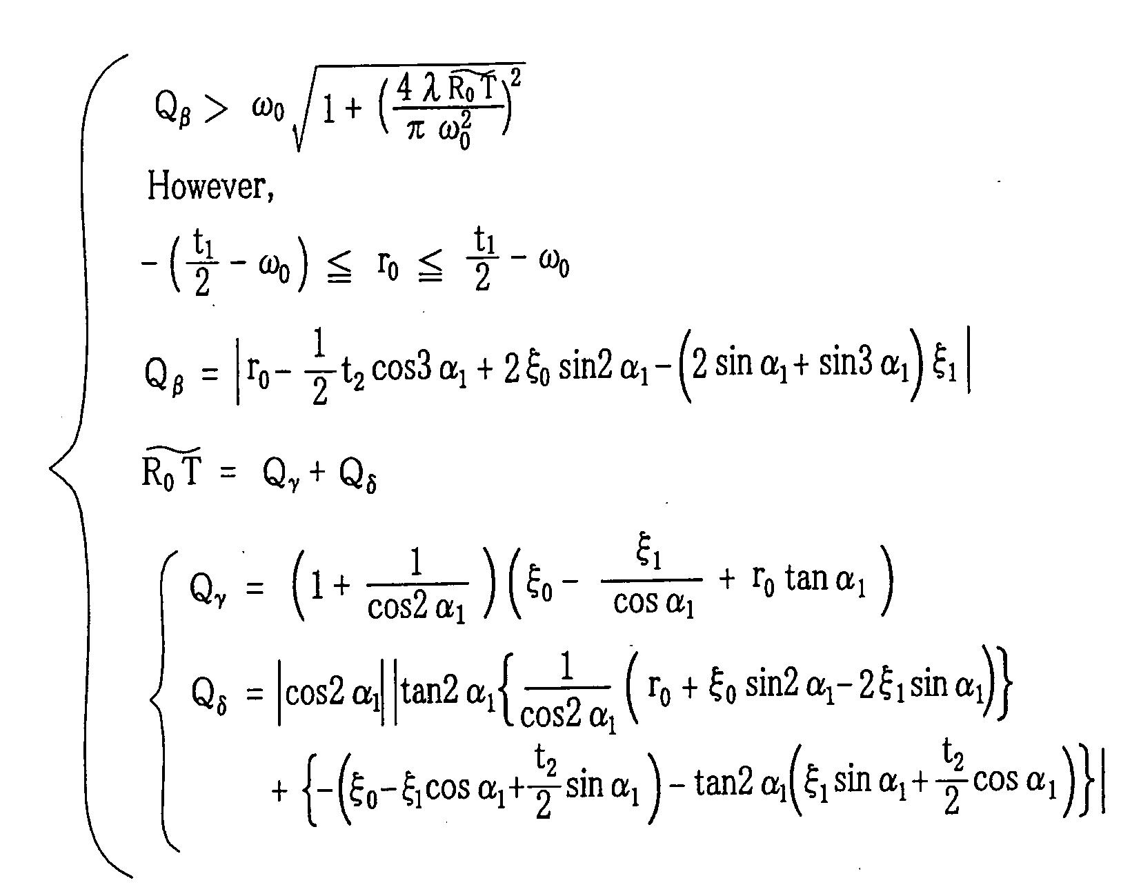
- A light scanning device as claimed in claim 4, wherein said first lens unit is an fθ lens for converging said light beam in said main scanning direction.
- A light scanning device (2) for focusing a light beam onto a scanned surface through a scanning lens group (6) after deflecting said light beam emitted from a light source (3) by a rotating deflector (5), said light scanning device comprising:first and second fθ lenses (17, 18), disposed one by one from said deflector, being included in said scanning lens group, said first and second fθ lenses being arranged such that their optical axes (24, 25) are respectively inclined at inclination angles α1 and α2 to a main scanning plane,wherein said inclination angles α1 and α2 satisfy the following condition:

- A light scanning device as claimed in claim 6, further comprising: at least one optical member (21) for reflecting said light beam from said scanning lens group toward said scanned surface;
wherein said inclination angles α1 and α2 are determined such that said light beam reflected plural times between said first and second fθ lenses does not enter said optical member. - A light scanning device as claimed in claim 7, wherein said inclination angle α1 of said first fθ lens satisfies the following mathematical expression:

where λ is a wave length of the longest light beam; ω0 is a beam waist diameter of said light beam having wave length λ near a reflective surface (5a) of said deflector; ξ0 is distance from a reflection point of said light beam on said reflective surface of said deflector to a flat surface perpendicular to said main scanning plane, and said flat surface includes a center axis (24) of said first fθ lens; ξ1 is distance from said center axis of said first fθ lens to a light entering surface (17a) of said first fθ lens; r0 is distance from a flat surface parallel to said main scanning plane to said reflection point of said light beam on said reflective surface of said deflector, and said flat surface includes said center axis of said first fθ lens; and t0 is width in a sub-scanning correspondence direction of said reflective surface of said deflector. - A light scanning device as claimed in claim 7, wherein said inclination angle α1 of said first fθ lens satisfies the following mathematical expression:

where λ is a wave length of the longest light beam; ω0 is a beam waist diameter of said light beam having wave length λ near a reflective surface (5a) of said deflector; ξ0 is distance from a reflection point of said light beam on said reflective surface of said deflector to a flat surface perpendicular to said main scanning plane, and said flat surface includes a center axis (24) of said first fθ lens; ξ1 is distance from said center axis of said first fθ lens to a light entering surface (17a) of said first fθ lens; r0 is distance from a flat surface parallel to said main scanning plane to said reflection point of said light beam on said reflective surface of said deflector, and said flat surface includes said center axis of said first fθ lens; t1 is width in a sub-scanning correspondence direction of said reflective surface of said deflector; and t2 is width in said sub-scanning correspondence direction of said light entering surface of said first fθ lens. - A light scanning device as claimed in claim 9, wherein said light source is constituted of plural light sources (4).
- A light scanning device as claimed in claim 10, wherein a scanning object is a photographic sensitive material.
Applications Claiming Priority (1)
| Application Number | Priority Date | Filing Date | Title |
|---|---|---|---|
| JP2004222081A JP2006039399A (en) | 2004-07-29 | 2004-07-29 | Optical scanner |
Publications (2)
| Publication Number | Publication Date |
|---|---|
| EP1621917A1 true EP1621917A1 (en) | 2006-02-01 |
| EP1621917B1 EP1621917B1 (en) | 2008-05-28 |
Family
ID=34937921
Family Applications (1)
| Application Number | Title | Priority Date | Filing Date |
|---|---|---|---|
| EP05016420A Expired - Lifetime EP1621917B1 (en) | 2004-07-29 | 2005-07-28 | Light scanning device |
Country Status (4)
| Country | Link |
|---|---|
| US (1) | US7038823B2 (en) |
| EP (1) | EP1621917B1 (en) |
| JP (1) | JP2006039399A (en) |
| DE (1) | DE602005007117D1 (en) |
Cited By (2)
| Publication number | Priority date | Publication date | Assignee | Title |
|---|---|---|---|---|
| EP1898248A1 (en) * | 2006-09-11 | 2008-03-12 | Samsung Electronics Co., Ltd. | Laser scanning unit and image forming apparatus having the same |
| EP2204687A1 (en) | 2008-12-31 | 2010-07-07 | Samsung Electronics Co., Ltd. | Light Scanning Unit |
Families Citing this family (9)
| Publication number | Priority date | Publication date | Assignee | Title |
|---|---|---|---|---|
| JP4786563B2 (en) | 2007-01-29 | 2011-10-05 | 京セラミタ株式会社 | Optical scanning device |
| KR101678976B1 (en) * | 2008-12-31 | 2017-01-02 | 삼성전자주식회사 | Light scanning unit |
| JP5303346B2 (en) * | 2009-04-24 | 2013-10-02 | 京セラドキュメントソリューションズ株式会社 | Optical scanning apparatus and image forming apparatus having the same |
| JP5219950B2 (en) * | 2009-07-14 | 2013-06-26 | キヤノン株式会社 | Optical scanning device |
| JP5802468B2 (en) * | 2011-07-29 | 2015-10-28 | 京セラドキュメントソリューションズ株式会社 | Optical scanning device and image forming apparatus using the same |
| JP5849504B2 (en) * | 2011-08-03 | 2016-01-27 | 株式会社リコー | Optical scanning apparatus and image forming apparatus |
| JP6478560B2 (en) * | 2014-10-29 | 2019-03-06 | キヤノン株式会社 | Optical scanning device and image forming apparatus using the same |
| US12566328B2 (en) * | 2022-09-29 | 2026-03-03 | Kyocera Document Solutions Inc. | Optical scanning device and image forming apparatus |
| US20250328005A1 (en) * | 2022-10-19 | 2025-10-23 | Cornell University | Optical scanner and scanning method |
Citations (2)
| Publication number | Priority date | Publication date | Assignee | Title |
|---|---|---|---|---|
| JPH0933842A (en) * | 1995-07-19 | 1997-02-07 | Ricoh Co Ltd | Optical scanning device |
| US5646767A (en) * | 1993-12-22 | 1997-07-08 | Asahi Kogaku Kogyo Kabushiki Kaisha | Scanning optical system |
Family Cites Families (3)
| Publication number | Priority date | Publication date | Assignee | Title |
|---|---|---|---|---|
| JPH05346553A (en) | 1992-06-15 | 1993-12-27 | Topcon Corp | Optical scanning device |
| JP3486293B2 (en) | 1996-04-08 | 2004-01-13 | ペンタックス株式会社 | Scanning optical system |
| JP3492971B2 (en) * | 2000-03-22 | 2004-02-03 | 株式会社リコー | Optical scanning device, scanning optical system, scanning image forming optical element, optical scanning method, ghost image prevention method, image forming apparatus |
-
2004
- 2004-07-29 JP JP2004222081A patent/JP2006039399A/en active Pending
-
2005
- 2005-07-28 DE DE602005007117T patent/DE602005007117D1/en not_active Expired - Lifetime
- 2005-07-28 US US11/190,921 patent/US7038823B2/en not_active Expired - Fee Related
- 2005-07-28 EP EP05016420A patent/EP1621917B1/en not_active Expired - Lifetime
Patent Citations (2)
| Publication number | Priority date | Publication date | Assignee | Title |
|---|---|---|---|---|
| US5646767A (en) * | 1993-12-22 | 1997-07-08 | Asahi Kogaku Kogyo Kabushiki Kaisha | Scanning optical system |
| JPH0933842A (en) * | 1995-07-19 | 1997-02-07 | Ricoh Co Ltd | Optical scanning device |
Cited By (3)
| Publication number | Priority date | Publication date | Assignee | Title |
|---|---|---|---|---|
| EP1898248A1 (en) * | 2006-09-11 | 2008-03-12 | Samsung Electronics Co., Ltd. | Laser scanning unit and image forming apparatus having the same |
| EP2204687A1 (en) | 2008-12-31 | 2010-07-07 | Samsung Electronics Co., Ltd. | Light Scanning Unit |
| US8305673B2 (en) | 2008-12-31 | 2012-11-06 | Samsung Electronics Co., Ltd. | Light scanning unit |
Also Published As
| Publication number | Publication date |
|---|---|
| US20060023283A1 (en) | 2006-02-02 |
| EP1621917B1 (en) | 2008-05-28 |
| JP2006039399A (en) | 2006-02-09 |
| US7038823B2 (en) | 2006-05-02 |
| DE602005007117D1 (en) | 2008-07-10 |
Similar Documents
| Publication | Publication Date | Title |
|---|---|---|
| US6064417A (en) | Laser printer using multiple sets of lasers with multiple wavelengths | |
| EP1970748B1 (en) | Optical scanning device and image forming apparatus using the same | |
| US8228583B2 (en) | Optical scanning device and image forming apparatus | |
| US20040233495A1 (en) | Light scanner, multibeam scanner, and image forming apparatus using the same | |
| EP1621917B1 (en) | Light scanning device | |
| EP1011003B1 (en) | Light-scanning optical system and image-forming apparatus comprising the same | |
| US10761450B2 (en) | Optical scanning apparatus and image forming apparatus | |
| EP1939666B1 (en) | Optical scanning device and image forming apparatus using the same | |
| US20040047018A1 (en) | Scanning optical system | |
| US11803050B2 (en) | Optical scanning device and electronic imaging apparatus | |
| US20100315477A1 (en) | Optical scanning device and image forming apparatus | |
| US20210325666A1 (en) | Optical scanning device and imaging apparatus | |
| EP2003483B1 (en) | Method of forming an optical scanner with aberration correction | |
| EP2602669A2 (en) | Laser scanning unit and colour image forming apparatus including the same | |
| EP1336889B1 (en) | Scanning optical apparatus and image forming apparatus using the same | |
| US11592663B2 (en) | Light detecting apparatus and light scanning apparatus | |
| US11381703B2 (en) | Light scanning apparatus and image forming apparatus | |
| US6650454B2 (en) | Multi-beam scanning optical system and image forming apparatus using the same | |
| JP3402010B2 (en) | Optical scanning device | |
| US20080062495A1 (en) | Laser scanning unit and image forming apparatus having the same | |
| EP0138400B1 (en) | Optical scanning apparatus including polygonal scanning mirror assembly | |
| US7119935B2 (en) | Light scanning unit for use in image forming apparatus | |
| US20040100672A1 (en) | Optical scanning device, image reading device provided with this, image forming device, and photographing device | |
| EP1701198A1 (en) | Optical scanning apparatus and image forming apparatus using the same | |
| US7034972B2 (en) | Optical scanning device and image forming apparatus using the optical scanning device |
Legal Events
| Date | Code | Title | Description |
|---|---|---|---|
| PUAI | Public reference made under article 153(3) epc to a published international application that has entered the european phase |
Free format text: ORIGINAL CODE: 0009012 |
|
| AK | Designated contracting states |
Kind code of ref document: A1 Designated state(s): AT BE BG CH CY CZ DE DK EE ES FI FR GB GR HU IE IS IT LI LT LU LV MC NL PL PT RO SE SI SK TR |
|
| AX | Request for extension of the european patent |
Extension state: AL BA HR MK YU |
|
| 17P | Request for examination filed |
Effective date: 20060622 |
|
| 17Q | First examination report despatched |
Effective date: 20060726 |
|
| AKX | Designation fees paid |
Designated state(s): DE FR GB |
|
| RAP1 | Party data changed (applicant data changed or rights of an application transferred) |
Owner name: FUJIFILM CORPORATION |
|
| GRAP | Despatch of communication of intention to grant a patent |
Free format text: ORIGINAL CODE: EPIDOSNIGR1 |
|
| GRAS | Grant fee paid |
Free format text: ORIGINAL CODE: EPIDOSNIGR3 |
|
| GRAA | (expected) grant |
Free format text: ORIGINAL CODE: 0009210 |
|
| AK | Designated contracting states |
Kind code of ref document: B1 Designated state(s): DE FR GB |
|
| REG | Reference to a national code |
Ref country code: GB Ref legal event code: FG4D |
|
| REF | Corresponds to: |
Ref document number: 602005007117 Country of ref document: DE Date of ref document: 20080710 Kind code of ref document: P |
|
| PLBE | No opposition filed within time limit |
Free format text: ORIGINAL CODE: 0009261 |
|
| STAA | Information on the status of an ep patent application or granted ep patent |
Free format text: STATUS: NO OPPOSITION FILED WITHIN TIME LIMIT |
|
| 26N | No opposition filed |
Effective date: 20090303 |
|
| REG | Reference to a national code |
Ref country code: FR Ref legal event code: PLFP Year of fee payment: 12 |
|
| PGFP | Annual fee paid to national office [announced via postgrant information from national office to epo] |
Ref country code: FR Payment date: 20160613 Year of fee payment: 12 |
|
| PGFP | Annual fee paid to national office [announced via postgrant information from national office to epo] |
Ref country code: DE Payment date: 20160720 Year of fee payment: 12 Ref country code: GB Payment date: 20160727 Year of fee payment: 12 |
|
| REG | Reference to a national code |
Ref country code: DE Ref legal event code: R082 Ref document number: 602005007117 Country of ref document: DE Representative=s name: KLUNKER IP PATENTANWAELTE PARTG MBB, DE |
|
| REG | Reference to a national code |
Ref country code: DE Ref legal event code: R119 Ref document number: 602005007117 Country of ref document: DE |
|
| GBPC | Gb: european patent ceased through non-payment of renewal fee |
Effective date: 20170728 |
|
| REG | Reference to a national code |
Ref country code: FR Ref legal event code: ST Effective date: 20180330 |
|
| PG25 | Lapsed in a contracting state [announced via postgrant information from national office to epo] |
Ref country code: GB Free format text: LAPSE BECAUSE OF NON-PAYMENT OF DUE FEES Effective date: 20170728 Ref country code: DE Free format text: LAPSE BECAUSE OF NON-PAYMENT OF DUE FEES Effective date: 20180201 |
|
| PG25 | Lapsed in a contracting state [announced via postgrant information from national office to epo] |
Ref country code: FR Free format text: LAPSE BECAUSE OF NON-PAYMENT OF DUE FEES Effective date: 20170731 |