EP1621812A1 - A combustion chamber device - Google Patents
A combustion chamber device Download PDFInfo
- Publication number
- EP1621812A1 EP1621812A1 EP04425495A EP04425495A EP1621812A1 EP 1621812 A1 EP1621812 A1 EP 1621812A1 EP 04425495 A EP04425495 A EP 04425495A EP 04425495 A EP04425495 A EP 04425495A EP 1621812 A1 EP1621812 A1 EP 1621812A1
- Authority
- EP
- European Patent Office
- Prior art keywords
- combustion chamber
- shell
- combustion
- chamber device
- internal surface
- Prior art date
- Legal status (The legal status is an assumption and is not a legal conclusion. Google has not performed a legal analysis and makes no representation as to the accuracy of the status listed.)
- Withdrawn
Links
Images


Classifications
-
- F—MECHANICAL ENGINEERING; LIGHTING; HEATING; WEAPONS; BLASTING
- F23—COMBUSTION APPARATUS; COMBUSTION PROCESSES
- F23C—METHODS OR APPARATUS FOR COMBUSTION USING FLUID FUEL OR SOLID FUEL SUSPENDED IN A CARRIER GAS OR AIR
- F23C15/00—Apparatus in which combustion takes place in pulses influenced by acoustic resonance in a gas mass
-
- F—MECHANICAL ENGINEERING; LIGHTING; HEATING; WEAPONS; BLASTING
- F23—COMBUSTION APPARATUS; COMBUSTION PROCESSES
- F23C—METHODS OR APPARATUS FOR COMBUSTION USING FLUID FUEL OR SOLID FUEL SUSPENDED IN A CARRIER GAS OR AIR
- F23C99/00—Subject-matter not provided for in other groups of this subclass
- F23C99/001—Applying electric means or magnetism to combustion
-
- F—MECHANICAL ENGINEERING; LIGHTING; HEATING; WEAPONS; BLASTING
- F23—COMBUSTION APPARATUS; COMBUSTION PROCESSES
- F23C—METHODS OR APPARATUS FOR COMBUSTION USING FLUID FUEL OR SOLID FUEL SUSPENDED IN A CARRIER GAS OR AIR
- F23C2900/00—Special features of, or arrangements for combustion apparatus using fluid fuels or solid fuels suspended in air; Combustion processes therefor
- F23C2900/03001—Miniaturized combustion devices using fluid fuels
Definitions
- the present invention relates to a combustion chamber device including at least one combustion chamber, in particular a microcombustion chamber, comprising a substantially tubular body which is closed at one end and in which a chamber for supplying and igniting a combustible mixture is defined and communicates with a duct which has a length which is far greater than the mean transverse dimension thereof and which can allow the generation and propagation of combustion, and of the resultant pressure wave, and the change-over from a slow deflagration condition to a rapid deflagration condition and/or from the deflagration condition to the detonation condition.
- a combustion chamber device including at least one combustion chamber, in particular a microcombustion chamber, comprising a substantially tubular body which is closed at one end and in which a chamber for supplying and igniting a combustible mixture is defined and communicates with a duct which has a length which is far greater than the mean transverse dimension thereof and which can allow the generation and propagation of combustion, and of the resultant
- Microcombustion chambers of this type have very small dimensions, with diameters, for example, in the order of 1 mm.
- An object of the present invention is to produce a combustion chamber device which prevents this disadvantage.
- a combustion chamber device of the type set out above, characterized primarily in that the body of the above-mentioned at least one combustion chamber is surrounded by and enclosed in a rigid external sealed shell which extends spaced apart from the wall of the body, forming, relative to the wall, a cavity or chamber which is insulated from the external environment and in which a vacuum is produced; the internal surface of the shell that faces the body being able to reflect, towards the body, a major portion of the energy which is radiated from the body during operation.
- a combustion chamber device according to the present invention is generally designated 1.
- This device comprises a (micro)combustion chamber 2 of the type known per se, including a body 3 of a substantially tubular shape which is produced, for example, from a metal material, in particular high-strength metal alloys.
- One end 3a of the tubular body 3 is closed and has a preferably flat internal profile, and the opposite end 3b is open and, preferably, the wall of the body 3 near this end has a progressively divergent shape in a nozzle-like manner, with a profile selected from those known in the art in order to facilitate the discharge of the gases and to maximize the reaction thrust.
- An igniting device 6 which is controlled during operation by way of a control line 7 is arranged in the chamber 4.
- the fuel and comburant can also be injected equally well at different points of the chamber, for example, by way of a small tube which extends through the body 3 and the shell 9, which will be described in greater detail below.
- the end chamber 4 communicates with a duct 8 having a length far greater than the mean transverse dimension thereof (for example, at least 20 times, and preferably more than 40 times the mean transverse dimension).
- the duct 8 is dimensioned and produced in such a manner as to allow, during operation, the generation and propagation of combustion and of the resultant pressure wave, as well as the change-over from the slow deflagration condition to the rapid deflagration condition and/or from the deflagration condition to the detonation condition.
- the transition from the slow deflagration condition to the rapid deflagration condition and then to the detonation condition is significant in order to be able to ensure greater efficiency of the combustion process.
- the body 3 of the microcombustion chamber 2 is surrounded by and enclosed in a rigid external sealed shell 9 which extends spaced apart from the wall of the body 3, forming relative thereto a cavity or chamber 10, which is insulated from the external environment.
- a vacuum is produced in the cavity or chamber 10.
- the internal surface 9a of the shell 9 that faces the body 3 of the microcombustion chamber 2 can reflect, towards the body, a major portion, and in particular the greatest possible quantity, of the energy which is radiated from the body during operation, as is indicated by the illustrative arrows shown in Figure 2.
- the shell 9 can be produced, for example, from a metal material, for example, gold, silver or aluminium, or it can be produced from a ceramic material having an internal surface with a reflective polished finish.
- the external surface 3c of the body 3 of the microcombustion chamber 2 advantageously has high absorbency and high emissivity with respect to the energy radiated from the body 3 during operation.
- This external surface 3c can preferably be constructed so as to have a grid for controlling the curve (lobe) of emission.
- the internal surface of the body 3 can instead be provided with projections which can facilitate the diffraction of the combustion front in order to ameliorate the turbulence and therefore the combustion itself.
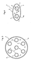
- Figure 3 shows a variant of a combustion chamber device 1 according to the present invention which comprises a plurality of microcombustion chambers 2 similar to that described above and arranged in a mutually parallel manner in a cylindrical circular external sealed shell 9, in which a vacuum is produced.
- the internal surface of the shell 9 is also able to reflect, towards the bodies 3 of the microcombustion chambers 2, a major portion of the energy which is radiated therefrom during operation.
- the external surfaces 3c of the bodies 3 of the microcombustion chambers 2 have high absorbency and high emissivity with respect to the energy radiated from the bodies of those microcombustion chambers during operation.
- Figure 4 illustrates another variant of embodiment.
- the same reference numerals used above have also been attributed once more to parts and elements which have already been described.
- the combustion chamber device 1 comprises a pair of microcombustion chambers 2 which are similar to that described above and which are arranged substantially parallel with one another inside a sealed shell 9 which has a reflective internal surface 9a which is cylindrical and has an elliptical cross-section.
- microcombustion chambers 2 are positioned with their axes substantially coincident with the focal lines F1 and F2 of the internal surface 9a of the shell 9. Owing to this feature, the energy radiated during operation from a microcombustion chamber 3 is reflected by the internal surface 9a of the shell 9 substantially and predominantly onto the other microcombustion chamber 3.
- Figure 5 shows another variant of a combustion chamber device according to the invention, comprising two pairs of microcombustion chambers 2 of the type described above, which are arranged substantially in parallel in a shell 9 which has a reflective cylindrical internal surface 9a, whose cross-section has a contour which corresponds substantially to the intersection of two ellipses having their larger axes orthogonal relative to each other.
- the microcombustion chambers 2 are arranged with their axes substantially coincident with the foci of these ellipses.
- Figure 6 schematically illustrates another variant of a combustion chamber device according to the invention.
- This variant is structurally similar to that described above with reference to Figure 1.
- the same reference numerals used above have also been attributed once more to parts and elements which have already been described.
- permanent magnets can also be associated similarly with the microcombustion chambers of the other combustion chamber devices 1 described above.
- the reflection, towards the microcombustion chamber(s), of the energy which is radiated thereby improves the efficiency during operation and effectively supports combustion, by limiting or eliminating the risk of quenching the flame.
- the cavity or chamber 10 under vacuum which is defined in the sealed shell 9 further allows the radial propagation of the noise generated during operation to be limited.
Landscapes
- Engineering & Computer Science (AREA)
- Chemical & Material Sciences (AREA)
- Combustion & Propulsion (AREA)
- Mechanical Engineering (AREA)
- General Engineering & Computer Science (AREA)
- Combustion Methods Of Internal-Combustion Engines (AREA)
Abstract
Description
- The present invention relates to a combustion chamber device including at least one combustion chamber, in particular a microcombustion chamber, comprising a substantially tubular body which is closed at one end and in which a chamber for supplying and igniting a combustible mixture is defined and communicates with a duct which has a length which is far greater than the mean transverse dimension thereof and which can allow the generation and propagation of combustion, and of the resultant pressure wave, and the change-over from a slow deflagration condition to a rapid deflagration condition and/or from the deflagration condition to the detonation condition.
- Microcombustion chambers of this type have very small dimensions, with diameters, for example, in the order of 1 mm.
- When the dimensions of such a microcombustion chamber are reduced, the surface/volume ratio increases and, together with an increase in the heat dissipation, heat is also transferred to the walls and the flame may be extinguished (so-called "wall quenching").
- An object of the present invention is to produce a combustion chamber device which prevents this disadvantage.
- This object and other objects are achieved according to the invention by means of a combustion chamber device of the type set out above, characterized primarily in that the body of the above-mentioned at least one combustion chamber is surrounded by and enclosed in a rigid external sealed shell which extends spaced apart from the wall of the body, forming, relative to the wall, a cavity or chamber which is insulated from the external environment and in which a vacuum is produced; the internal surface of the shell that faces the body being able to reflect, towards the body, a major portion of the energy which is radiated from the body during operation.
- Since the above-mentioned cavity or chamber is under vacuum, an energy exchange is effected therein during operation substantially only by radiant means. The energy which is radiated from the combustion chamber and reflected back onto the combustion chamber allows a good recovery of the thermal energy which would otherwise be dissipated, increasing the overall efficiency and thereby avoiding the risk of quenching of the combustion flame.
- Other characteristics and advantages of the invention will become clear from the following detailed description which is given purely by way of non-limiting example with reference to the appended drawings, in which:
- Figure 1 is a schematic axially sectioned illustration of a combustion chamber device according to the present invention comprising a single combustion chamber;
- Figure 2 is a cross-section along line II-II of Figure 1;
- Figure 3 is a cross-section of another combustion chamber device according to the invention, comprising a plurality of combustion chambers which are enclosed in a reflective shell of circular cylindrical shape;
- Figure 4 shows another combustion chamber device according to the present invention, comprising a pair of combustion chambers enclosed in a reflective shell having an elliptical cylindrical shape;
- Figure 5 is a cross-section of another combustion chamber device according to the present invention comprising four combustion chambers which are arranged inside a reflective shell, whose cross-section has a profile which corresponds substantially to the intersection of two ellipses; and
- Figure 6 is an axially sectioned view of another combustion chamber device according to the present invention, provided with permanent magnets for exploiting the hydromagnetic effect.
- In Figures 1 and 2, a combustion chamber device according to the present invention is generally designated 1. This device comprises a (micro)
combustion chamber 2 of the type known per se, including abody 3 of a substantially tubular shape which is produced, for example, from a metal material, in particular high-strength metal alloys. - One
end 3a of thetubular body 3 is closed and has a preferably flat internal profile, and theopposite end 3b is open and, preferably, the wall of thebody 3 near this end has a progressively divergent shape in a nozzle-like manner, with a profile selected from those known in the art in order to facilitate the discharge of the gases and to maximize the reaction thrust. - A
chamber 4 for supplying and igniting a combustible mixture, which is supplied to thechamber 4 by way of at least one inlet connection, indicated 5, is defined inside thebody 3 near the closedend 3a thereof. Anigniting device 6 which is controlled during operation by way of acontrol line 7 is arranged in thechamber 4. However, the fuel and comburant can also be injected equally well at different points of the chamber, for example, by way of a small tube which extends through thebody 3 and theshell 9, which will be described in greater detail below. - In the
body 3 of the microcombustion chamber, theend chamber 4 communicates with aduct 8 having a length far greater than the mean transverse dimension thereof (for example, at least 20 times, and preferably more than 40 times the mean transverse dimension). Theduct 8 is dimensioned and produced in such a manner as to allow, during operation, the generation and propagation of combustion and of the resultant pressure wave, as well as the change-over from the slow deflagration condition to the rapid deflagration condition and/or from the deflagration condition to the detonation condition. - The transition from the slow deflagration condition to the rapid deflagration condition and then to the detonation condition is significant in order to be able to ensure greater efficiency of the combustion process.
- The
body 3 of themicrocombustion chamber 2 is surrounded by and enclosed in a rigid external sealedshell 9 which extends spaced apart from the wall of thebody 3, forming relative thereto a cavity orchamber 10, which is insulated from the external environment. - A vacuum is produced in the cavity or
chamber 10. - The
internal surface 9a of theshell 9 that faces thebody 3 of themicrocombustion chamber 2 can reflect, towards the body, a major portion, and in particular the greatest possible quantity, of the energy which is radiated from the body during operation, as is indicated by the illustrative arrows shown in Figure 2. - The
shell 9 can be produced, for example, from a metal material, for example, gold, silver or aluminium, or it can be produced from a ceramic material having an internal surface with a reflective polished finish. - The
external surface 3c of thebody 3 of themicrocombustion chamber 2 advantageously has high absorbency and high emissivity with respect to the energy radiated from thebody 3 during operation. Thisexternal surface 3c can preferably be constructed so as to have a grid for controlling the curve (lobe) of emission. - The internal surface of the
body 3 can instead be provided with projections which can facilitate the diffraction of the combustion front in order to ameliorate the turbulence and therefore the combustion itself. - Figure 3 shows a variant of a combustion chamber device 1 according to the present invention which comprises a plurality of
microcombustion chambers 2 similar to that described above and arranged in a mutually parallel manner in a cylindrical circular external sealedshell 9, in which a vacuum is produced. - In this case, the internal surface of the
shell 9 is also able to reflect, towards thebodies 3 of themicrocombustion chambers 2, a major portion of the energy which is radiated therefrom during operation. Theexternal surfaces 3c of thebodies 3 of themicrocombustion chambers 2 have high absorbency and high emissivity with respect to the energy radiated from the bodies of those microcombustion chambers during operation. - Figure 4 illustrates another variant of embodiment. In this Figure, the same reference numerals used above have also been attributed once more to parts and elements which have already been described.
- In the configuration according to Figure 4, the combustion chamber device 1 comprises a pair of
microcombustion chambers 2 which are similar to that described above and which are arranged substantially parallel with one another inside a sealedshell 9 which has a reflectiveinternal surface 9a which is cylindrical and has an elliptical cross-section. - The
microcombustion chambers 2 are positioned with their axes substantially coincident with the focal lines F1 and F2 of theinternal surface 9a of theshell 9. Owing to this feature, the energy radiated during operation from amicrocombustion chamber 3 is reflected by theinternal surface 9a of theshell 9 substantially and predominantly onto theother microcombustion chamber 3. - Figure 5 shows another variant of a combustion chamber device according to the invention, comprising two pairs of
microcombustion chambers 2 of the type described above, which are arranged substantially in parallel in ashell 9 which has a reflective cylindricalinternal surface 9a, whose cross-section has a contour which corresponds substantially to the intersection of two ellipses having their larger axes orthogonal relative to each other. Themicrocombustion chambers 2 are arranged with their axes substantially coincident with the foci of these ellipses. - Finally, Figure 6 schematically illustrates another variant of a combustion chamber device according to the invention. This variant is structurally similar to that described above with reference to Figure 1. In Figure 6, the same reference numerals used above have also been attributed once more to parts and elements which have already been described.
- In the variant according to Figure 6, with a view to generating energy based on the hydromagnetic effect, a plurality of
permanent magnets 20, which extend in the cavity orchamber 10 defined between themicrocombustion chamber 2 and the reflectiveexternal shell 9, are arranged around thebody 3 of themicrocombustion chamber 2. - Naturally, permanent magnets can also be associated similarly with the microcombustion chambers of the other combustion chamber devices 1 described above.
- As set out above, the reflection, towards the microcombustion chamber(s), of the energy which is radiated thereby improves the efficiency during operation and effectively supports combustion, by limiting or eliminating the risk of quenching the flame.
- In the case of combustion chamber devices used as thrusters, or for other applications, the cavity or
chamber 10 under vacuum which is defined in the sealedshell 9 further allows the radial propagation of the noise generated during operation to be limited. - Naturally, the principle of the invention remaining the same, the forms of embodiment and the details of construction may be varied widely with respect to those described and illustrated, which have been given purely by way of non-limiting example, without thereby departing from the scope of the invention, as defined in the appended claims.
Claims (8)
- A combustion chamber device (1), comprising at least one combustion chamber (2), in particular a microcombustion chamber, including a substantially tubular body (3) which is closed at one end (3a) and in which a chamber (4) for supplying and igniting a combustible mixture is defined and communicates with a duct (8) which has a length far greater than the mean transverse dimension thereof and which can allow the generation and propagation of combustion, and of the resultant pressure wave, as well as the change-over from a slow deflagration condition to a rapid deflagration condition and/or from the deflagration condition to the detonation condition;
characterized in that the body (3) is surrounded by and enclosed in a rigid external sealed shell (9) which extends spaced apart from the wall (3c) of the body (3), forming, relative to the wall, a cavity or chamber (10) which is insulated from the external environment and in which a vacuum is produced; the internal surface (9a) of the shell (9) that faces the body (3) being able to reflect, towards the body (3), a major portion of the energy which is radiated from the body (3) during operation. - A combustion chamber device according to claim 1, wherein the wall of the tubular body (3) which is enclosed by the shell (9) has a surface (3c) which has high absorbency and high emissivity with respect to the energy radiated from the body (3) during operation.
- A combustion chamber device according to either of the preceding claims, comprising at least a pair of substantially parallel combustion chambers (2), and wherein the shell (9) has internally at least a pair of cylindrical surface portions having an elliptical cross-section, and the combustion chambers (2) are each arranged on the focal line of one of the surface portions.
- A combustion chamber device according to claim 3, comprising a single pair of combustion chambers (2) which are arranged substantially in parallel, and wherein the shell (9) has an internal surface which is cylindrical having an elliptical cross-section, the combustion chambers (2) being arranged on the focal lines (F1, F2) of the internal surface (9a).
- A combustion chamber device according to claim 3, comprising at least two pairs of combustion chambers (2) which are arranged substantially in parallel, and wherein the shell (9) has a reflective cylindrical internal surface, whose cross-section has a contour which corresponds substantially to the intersection of at least two ellipses; the combustion chambers each being arranged on a focal line of the reflective internal surface (9a).
- A combustion chamber device according to any one of the preceding claims, wherein permanent magnets (20) for generating energy based on the hydromagnetic effect are associated with the combustion chamber(s) (2), the permanent magnets (20) being arranged around the body (3) of the or each combustion chamber (2), in the cavity (10) which is defined relative to the reflective shell (9).
- A combustion chamber device according to any one of the preceding claims, characterized in that the shell (9) is of metal material, in particular gold, aluminium or silver.
- A combustion chamber device according to any one of claims 1 to 6, wherein the shell (9) is of ceramic material, and the internal surface (9a) thereof has a polished reflective finish.
Priority Applications (1)
| Application Number | Priority Date | Filing Date | Title |
|---|---|---|---|
| EP04425495A EP1621812A1 (en) | 2004-07-07 | 2004-07-07 | A combustion chamber device |
Applications Claiming Priority (1)
| Application Number | Priority Date | Filing Date | Title |
|---|---|---|---|
| EP04425495A EP1621812A1 (en) | 2004-07-07 | 2004-07-07 | A combustion chamber device |
Publications (1)
| Publication Number | Publication Date |
|---|---|
| EP1621812A1 true EP1621812A1 (en) | 2006-02-01 |
Family
ID=34932613
Family Applications (1)
| Application Number | Title | Priority Date | Filing Date |
|---|---|---|---|
| EP04425495A Withdrawn EP1621812A1 (en) | 2004-07-07 | 2004-07-07 | A combustion chamber device |
Country Status (1)
| Country | Link |
|---|---|
| EP (1) | EP1621812A1 (en) |
Cited By (1)
| Publication number | Priority date | Publication date | Assignee | Title |
|---|---|---|---|---|
| CN121229170A (en) * | 2025-11-21 | 2025-12-30 | 中国矿业大学 | A smart collaborative system and method for the graded utilization of multi-concentration methane in deep coal mines |
Citations (2)
| Publication number | Priority date | Publication date | Assignee | Title |
|---|---|---|---|---|
| DE10118005A1 (en) * | 2001-04-10 | 2002-10-24 | Norbert Schwesinger | Micro-rocket operating with periodic explosive combustion, includes distributor, combustion chamber, igniter and flame traps in supply lines |
| US20020187447A1 (en) * | 2001-06-06 | 2002-12-12 | Sirignano William A. | Miniature, liquid-fueled combustion chamber |
-
2004
- 2004-07-07 EP EP04425495A patent/EP1621812A1/en not_active Withdrawn
Patent Citations (2)
| Publication number | Priority date | Publication date | Assignee | Title |
|---|---|---|---|---|
| DE10118005A1 (en) * | 2001-04-10 | 2002-10-24 | Norbert Schwesinger | Micro-rocket operating with periodic explosive combustion, includes distributor, combustion chamber, igniter and flame traps in supply lines |
| US20020187447A1 (en) * | 2001-06-06 | 2002-12-12 | Sirignano William A. | Miniature, liquid-fueled combustion chamber |
Cited By (1)
| Publication number | Priority date | Publication date | Assignee | Title |
|---|---|---|---|---|
| CN121229170A (en) * | 2025-11-21 | 2025-12-30 | 中国矿业大学 | A smart collaborative system and method for the graded utilization of multi-concentration methane in deep coal mines |
Similar Documents
| Publication | Publication Date | Title |
|---|---|---|
| CA2422955C (en) | Shock wave reflector and detonation chamber | |
| US4741154A (en) | Rotary detonation engine | |
| JP5633909B2 (en) | Burner system and method for increasing the efficiency of a heat exchanger | |
| US6523475B2 (en) | Firearm cartridge and case-less chamber | |
| EP2011989A3 (en) | Pulse detonation engine operating with a mix of fuel and air | |
| EP2327867A2 (en) | Thrust modulation in a multiple combustor pulse detonation engine using cross-combustor detonation initiation | |
| CN107131803B (en) | Shock Focused Flame Focused Detonator | |
| KR20210045937A (en) | Multi-dimensional ceramic burner surface | |
| Callahan et al. | Progress in heavy ion target capsule and hohlraum design | |
| EP1546608B1 (en) | Multiple plate combustor | |
| CN108915893B (en) | A multi-tube helical pulse detonation engine | |
| RU2215890C2 (en) | Thrust forming method and device | |
| EP1543926A3 (en) | Combustion chamber arrangement in combustion type power tool | |
| CN102606343A (en) | Detonation chamber of pulse detonation engine | |
| CN110778419A (en) | Detonating device for detonation combustor | |
| US7794293B2 (en) | Marine propulsion system and marine vessel having same | |
| JPS58178852A (en) | Stirling engine | |
| RU2227249C2 (en) | Gas dynamic infra-red radiator | |
| CN113048515A (en) | Combustion chamber, engine and aircraft based on supersonic stamping oblique detonation | |
| Koenig et al. | Radiative shock experiment using high power laser | |
| CN215676696U (en) | A heater that is used for explosion formula propeller of forest fire extinguishing bomb | |
| CN118729327B (en) | Shock wave focusing detonation device and control method thereof | |
| US3157029A (en) | Jet engine | |
| CN121876473A (en) | Device and method for realizing efficient extraction of graded detonation energy | |
| RU2793353C1 (en) | Heat-insulating cap of the gasostatic furnace |
Legal Events
| Date | Code | Title | Description |
|---|---|---|---|
| PUAI | Public reference made under article 153(3) epc to a published international application that has entered the european phase |
Free format text: ORIGINAL CODE: 0009012 |
|
| AK | Designated contracting states |
Kind code of ref document: A1 Designated state(s): AT BE BG CH CY CZ DE DK EE ES FI FR GB GR HU IE IT LI LU MC NL PL PT RO SE SI SK TR |
|
| AX | Request for extension of the european patent |
Extension state: AL HR LT LV MK |
|
| 17P | Request for examination filed |
Effective date: 20060710 |
|
| AKX | Designation fees paid |
Designated state(s): AT BE BG CH CY CZ DE DK EE ES FI FR GB GR HU IE IT LI LU MC NL PL PT RO SE SI SK TR |
|
| STAA | Information on the status of an ep patent application or granted ep patent |
Free format text: STATUS: THE APPLICATION HAS BEEN WITHDRAWN |
|
| 18W | Application withdrawn |
Effective date: 20071010 |