EP1621395B1 - Child car seat adaptable to child growth - Google Patents
Child car seat adaptable to child growth Download PDFInfo
- Publication number
- EP1621395B1 EP1621395B1 EP05105512A EP05105512A EP1621395B1 EP 1621395 B1 EP1621395 B1 EP 1621395B1 EP 05105512 A EP05105512 A EP 05105512A EP 05105512 A EP05105512 A EP 05105512A EP 1621395 B1 EP1621395 B1 EP 1621395B1
- Authority
- EP
- European Patent Office
- Prior art keywords
- backrest
- headrest
- sidepieces
- control means
- child seat
- Prior art date
- Legal status (The legal status is an assumption and is not a legal conclusion. Google has not performed a legal analysis and makes no representation as to the accuracy of the status listed.)
- Expired - Lifetime
Links
Images


Classifications
-
- B—PERFORMING OPERATIONS; TRANSPORTING
- B60—VEHICLES IN GENERAL
- B60N—SEATS SPECIALLY ADAPTED FOR VEHICLES; VEHICLE PASSENGER ACCOMMODATION NOT OTHERWISE PROVIDED FOR
- B60N2/00—Seats specially adapted for vehicles; Arrangement or mounting of seats in vehicles
- B60N2/02—Seats specially adapted for vehicles; Arrangement or mounting of seats in vehicles the seat or part thereof being movable, e.g. adjustable
- B60N2/0296—Central command actuator to selectively switch on or engage one of several special purpose circuits or mechanisms
-
- B—PERFORMING OPERATIONS; TRANSPORTING
- B60—VEHICLES IN GENERAL
- B60N—SEATS SPECIALLY ADAPTED FOR VEHICLES; VEHICLE PASSENGER ACCOMMODATION NOT OTHERWISE PROVIDED FOR
- B60N2/00—Seats specially adapted for vehicles; Arrangement or mounting of seats in vehicles
- B60N2/24—Seats specially adapted for vehicles; Arrangement or mounting of seats in vehicles for particular purposes or particular vehicles
- B60N2/26—Seats specially adapted for vehicles; Arrangement or mounting of seats in vehicles for particular purposes or particular vehicles for children
- B60N2/28—Seats readily mountable on, and dismountable from, existing seats or other parts of the vehicle
- B60N2/2851—Seats readily mountable on, and dismountable from, existing seats or other parts of the vehicle provided with head-rests
-
- B—PERFORMING OPERATIONS; TRANSPORTING
- B60—VEHICLES IN GENERAL
- B60N—SEATS SPECIALLY ADAPTED FOR VEHICLES; VEHICLE PASSENGER ACCOMMODATION NOT OTHERWISE PROVIDED FOR
- B60N2/00—Seats specially adapted for vehicles; Arrangement or mounting of seats in vehicles
- B60N2/24—Seats specially adapted for vehicles; Arrangement or mounting of seats in vehicles for particular purposes or particular vehicles
- B60N2/26—Seats specially adapted for vehicles; Arrangement or mounting of seats in vehicles for particular purposes or particular vehicles for children
- B60N2/28—Seats readily mountable on, and dismountable from, existing seats or other parts of the vehicle
- B60N2/2866—Seats readily mountable on, and dismountable from, existing seats or other parts of the vehicle booster cushions, e.g. to lift a child to allow proper use of the conventional safety belts
-
- B—PERFORMING OPERATIONS; TRANSPORTING
- B60—VEHICLES IN GENERAL
- B60N—SEATS SPECIALLY ADAPTED FOR VEHICLES; VEHICLE PASSENGER ACCOMMODATION NOT OTHERWISE PROVIDED FOR
- B60N2/00—Seats specially adapted for vehicles; Arrangement or mounting of seats in vehicles
- B60N2/24—Seats specially adapted for vehicles; Arrangement or mounting of seats in vehicles for particular purposes or particular vehicles
- B60N2/26—Seats specially adapted for vehicles; Arrangement or mounting of seats in vehicles for particular purposes or particular vehicles for children
- B60N2/28—Seats readily mountable on, and dismountable from, existing seats or other parts of the vehicle
- B60N2/2872—Seats readily mountable on, and dismountable from, existing seats or other parts of the vehicle provided with side rests
-
- B—PERFORMING OPERATIONS; TRANSPORTING
- B60—VEHICLES IN GENERAL
- B60N—SEATS SPECIALLY ADAPTED FOR VEHICLES; VEHICLE PASSENGER ACCOMMODATION NOT OTHERWISE PROVIDED FOR
- B60N2/00—Seats specially adapted for vehicles; Arrangement or mounting of seats in vehicles
- B60N2/80—Head-rests
- B60N2/806—Head-rests movable or adjustable
- B60N2/809—Head-rests movable or adjustable vertically slidable
- B60N2/829—Head-rests movable or adjustable vertically slidable characterised by their adjusting mechanisms, e.g. electric motors
-
- B—PERFORMING OPERATIONS; TRANSPORTING
- B60—VEHICLES IN GENERAL
- B60N—SEATS SPECIALLY ADAPTED FOR VEHICLES; VEHICLE PASSENGER ACCOMMODATION NOT OTHERWISE PROVIDED FOR
- B60N2/00—Seats specially adapted for vehicles; Arrangement or mounting of seats in vehicles
- B60N2/02—Seats specially adapted for vehicles; Arrangement or mounting of seats in vehicles the seat or part thereof being movable, e.g. adjustable
- B60N2002/0288—Adjustable seat width
Definitions
- the said groove 53 houses a cable 56 having a first cable terminal 57 rigid with a slide block 58 movable between the support element 14 and the rear portion 13 of the backrest 3.
- a second cable terminal 60 is rigid with a pulley 61 rotatably inserted into a corresponding seat 62 rigid with the inner face 43 of the rear portion 13 of the backrest 3.
- the aforesaid adjustments are easily available to the user even when the child seat is mounted on the seat of a vehicle.
Landscapes
- Engineering & Computer Science (AREA)
- Aviation & Aerospace Engineering (AREA)
- Transportation (AREA)
- Mechanical Engineering (AREA)
- Health & Medical Sciences (AREA)
- Child & Adolescent Psychology (AREA)
- General Health & Medical Sciences (AREA)
- Seats For Vehicles (AREA)
- Carriages For Children, Sleds, And Other Hand-Operated Vehicles (AREA)
Abstract
Description
- The present invention relates to a child car seat in accordance with the introduction to the main claim.
- Various types of child seats, and in particular child car seats, are known having dimensions adjustable as the child grows. With particular reference to child seats presenting a backrest provided with movable sidepieces and a movable headrest, some known models enable the head rest and said sidepieces to be moved together, while others enable said sidepieces and headrest to be moved separately. The present invention relates to a child seat of this latter type.
- In state of the art child seats of the aforesaid type, the headrest and sidepieces are moved independently by generally acting directly on the headrest to move it longitudinally along the backrest, while operating independent control members to adjust the relative distance between said sidepieces. Although these solutions enable the backrest to be adjusted in line with the various growth stages of the child, they are not easy to use as the elements or members for controlling the separate movements of the various parts of the backrest are generally positioned at a different distance apart. As a result the user has to move along the backrest to obtain the desired adjustment, this being a movement not always easy to make especially if the child seat is already disposed in its position of use on the seat of a car. In this respect, as at least the members for controlling the movement of the sidepieces are positioned on the rear of the backrest, when the child seat is already disposed in the car these members are not reachable by the user. Consequently. in order to adjust the width of the backrest the user has to remove the child seat from its position of use.
-
DE 2011 8046 U1 shows a child car seat with the features of the preambule of claim 1. - An object of the present invention is to provide an improved child car seat presenting a backrest provided with laterally movable sidepieces to enable the width of the region accommodating the child to be widened, and a height-adjustable headrest enabling the height of the backrest to be adapted to the growth of the child, said sidepieces and said headrest being movable independently of each other.
- A particular object of the invention is to provide a child seat of the stated type in which said sidepieces and headrest can be easily and quickly moved even when the child seat is disposed on the seat of a car without the need to remove the child seat therefrom.
- A further object is to provide a child seat which enables the distance between said sidepieces to be adjusted independently of the position attained by the headrest.
- A further object is to provide a child seat in which the distance between said sidepieces can be adjusted continuously, hence allowing fine adjustment of the space on the backrest for accommodating the child.
- These and further objects which will be apparent to an expert of the art are attained by a child seat in accordance with the accompanying claims.
- The present invention will be more apparent from the accompanying drawings, which are provided by way of non-limiting example and in which
-
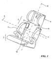
Figure 1 is a perspective view of a child seat according to the invention; -
Figure 2 is a front view of the backrest of the child seat ofFigure 1 showing the components used to move its parts; -
Figure 3 is a view similar toFigure 2 , but in which part of the child seat components are in a different position of use; -
Figure 4 is a section on the line 4-4 ofFigure 3 ; -
Figure 5 is an exploded front view of a part of the child seat backrest; and -
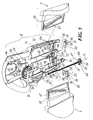
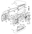
Figure 6 is an exploded rear perspective view, similar to that ofFigure 5 , but with the child seat backrest provided with a larger number of components. - With reference to said figures, a child car seat according to the invention is indicated overall by 1 and comprises a sitting
portion 2 and abackrest 3. This latter is provided with aheadrest 4 and, along itsside edges sidepieces 7. Theheadrest 4 can be moved along a longitudinal axis W of thebackrest 3 to adjust its distance from the sittingportion 2. Independently of theheadrest 4, thesidepieces 7 are also movable along a transverse axis K perpendicular to said axis W so that they can be moved away from or towards each other depending on the size of the child seated on the child seat 1. - In other words, the child seat of the invention is of the type which conforms to the growth of the child such as to adapt to the child by enabling its dimensions to be changed with child growth.
- As stated, the
headrest 4 and thesidepieces 7 can be moved independently of each other. This movement is obtained by respective first andsecond control members headrest 4 and advantageously and preferably disposed in correspondence with this latter. - More specifically, the
backrest 3 comprises a frontfirst portion 12 on which the child rests when seated on the child seat 1 and a rearsecond portion 13 acting as the rear "closure" for the backrest. Between theportions 12 and 13 abackrest support element 14 is provided coupled to the sittingportion 2 and presenting a pair of substantially rectangularparallel slots 15, each having along one of its parallel longer sides 16 a plurality of recesses 17 defining a sort of toothing along saidlonger side 16. This toothing cooperates withprojections 18 onslide blocks 19 arranged to cooperate with acontrol rod 20 operated by thefirst control member 10 rigid with therear portion 13 of thebackrest 3 and movable betweenguide elements 19A projecting from theportion 13 towards theelement 14. - More specifically, each
slide block 19 comprises abody 21 presenting aflat part 22 from which apin 23 rises to cooperate with acorresponding slit 24 provided in anend element 25 of thecontrol rod 20. These slits 24 (each arranged to cooperate with acorresponding slide block 19 which itself cooperates, as stated, with the recesses 17 of acorresponding slot 15 of the support element 14) are formed with their axes Z and T converging or inclined towards anend part 26 of saidend element 25. - The end element also comprises an
elongate hole 27 having its longitudinal axis lying along the longitudinal axis of the control rod 20 (corresponding to the axis W of the backrest), said elongate hole receiving apin 28 projecting from asupport 29 provided in therear portion 13 of thebackrest 3. Thispin 28 acts as a guide element for the movement of thecontrol rod 20 when operating the correspondingfirst control member 10 for moving theheadrest 4. - This latter is defined above the
front portion 12 andrear portion 13 of thebackrest 3 and by corresponding ends of these latter. Specifically, thefront portion 12 presents on thatflat face 4A facing therear portion 13 of thebackrest 3, aretention element 30 for securing thefirst control member 10 to thefront portion 12 of the backrest and hence to theheadrest 4. Thisretention element 30 is defined by a plurality ofprojections 31 jutting from theflat face 4A of theportion 12 to define seats 32 forpins 33 cooperating with holes orslits 34 provided in thefirst control member 10. Thesepins 33 secure the control member to thefront portion 12 of thebackrest 3 and hence to itsheadrest 4, and also guide saidfirst control member 10 in its axial movement along the longitudinal axis W of the backrest when this member is operated. - In detail, the
first control member 10 comprises a substantiallyrectangular body 37 presenting theslits 34 in predefined positions. Thebody 37 presents apin 39 arranged to snap-cooperate with ahole 40 provided at afree end 41 of thecontrol rod 20 to fix this rod to said control member. Thebody 37 is inserted between ribs orguides 42 projecting from thatface 43 of therear portion 13 of thebackrest 3 which faces thefront portion 12, saidribs 42 acting as guides for the movement of thebody 37 of thefirst control member 10 when operated by being gripped within arecess 45 provided in thebody 37 and reachable from the outside of therear portion 13 through anaperture 46 provided in this latter behind theheadrest 4 where thefirst control member 10 is positioned. The saidpins 33 for guiding the movement of thebody 37 between theguide ribs 42 also project from theinner face 43 of therear portion 13. - From the
face 43 of therear portion 13 there also projects anarched rib 50 at which there is positioned awheel 51 presenting agroove 53 in its edge. Thewheel 51 is supported by saidelement 30 retaining thefront portion 12 and is inserted into aseat 54 provided within thebody 37 of thecontrol member 10. Thewheel 51 defines thesecond control member 11 for moving thesidepieces 7 of the backrest. - The said
groove 53 houses acable 56 having afirst cable terminal 57 rigid with aslide block 58 movable between thesupport element 14 and therear portion 13 of thebackrest 3. Asecond cable terminal 60 is rigid with apulley 61 rotatably inserted into acorresponding seat 62 rigid with theinner face 43 of therear portion 13 of thebackrest 3. - The
slide block 58 presentsarms 64 having at a free end 65 a projectingpin 66 cooperating withinclined slots 67 provided inflat parts 68 rigid with thesidepieces 7 and inserted throughapertures 70 provided inlateral edges 71 of therear portion 13, between this latter and thesupport element 14. Theslide block 58 comprises a central portion 72 (with which thecable terminal 57 is rigid) slidable withinguides 73 defined by ribs projecting parallel from theinner face 43 of therear portion 13 of thebackrest 3. The movement of this slide block within said guides along therear portion 13 of the backrest results in sliding of thepins 66 within theinclined slots 67 of theflat parts 68 of themovable sidepieces 7. By virtue of this inclination, said sidepieces move transversely to the backrest, along the direction defined by the axis K inFigure 1 . - To achieve a complete excursion of the
sidepieces 7 within theapertures 70 of therear portion 13 of thebackrest 3, i.e. to enable the sidepieces to undergo total movement from a retracted position (Figure 2 ) to a completely external position (Figure 3 ), thewheel 51 must be rotated about is central axis through 180°. This rotation is achieved by acting on ahandgrip 75 provided on the central part of saidwheel 51. - It will now be assumed that the position of the
sidepieces 7 of thebackrest 3 is to be modified by moving them from the position shown inFigure 1 to the completely widened position ofFigure 3 . To achieve this, thehandgrip 75 of thewheel 51 is operated to rotate this latter within thebody 37 of thefirst control member 10 in correspondence with thearched rib 50 of therear portion 13 of thebackrest 3. This rotation results in a corresponding rotation of thepulley 61 about its axis and a movement of theslide block 58 between theguides 73 of saidrear portion 13. This movement brings the slide block from the position shown by dashed lines inFigure 2 to the raised position ofFigure 3 . During this movement, theslide block pins 66 slide relatively within theinclined slots 67 of theflat parts 68 of thesidepieces 7, which move within theapertures 70 and emerge from them. Consequently, when the slide block reaches the maximum position of its raising travel, said sidepieces are totally distant from thecorresponding edges 71 of therear portion 13 of thebackrest 3 and are wide apart. - If the position or height of the
headrest 4 is to be modified, thecontrol member 10 is operated by acting on thecable 45 of thebody 37 through theaperture 46 of the rear portion 13 (this aperture also providing access to thehandgrip 75 of thewheel 51, i.e. thesecond control member 11 for moving the sidepieces 7). Thebody 37 is then raised (in the manner of a slider along the ribs or guides 42) towards the upper end of the backrest to longitudinally move thecontrol rod 20 and cause thepin 28 to slide relatively within theelongate hole 27 present in theend element 25 of the sidepiece. This raising of thecontrol rod 20 results in a movement of thepins 23 of theslide blocks 19 within theslits 24 so that these slide blocks are made to approach each other within theguide elements 19A with movement in a direction perpendicular to the longitudinal axis W of thebackrest 3. It should be noted that this movement is opposed by an elastic element orspring 80 having afirst end 81 rigid with therear portion 13 of thebackrest 3 and asecond end 82 rigid with acoupling tooth 85 present at one end of thecorresponding slide block 19. - The slide blocks 19 hence move one towards the other to thus separate their
projections 18 from the corresponding recesses 17 in which they lie. Theseprojections 18 thus move into theparallel slots 15 of thesupport element 14 to enable the slide blocks 19, therod 20 and thebody 37 to be moved towards the upper end of thebackrest 3. This movement raises theportions portion 12 and within which thesupport element 14 lies, with consequent raising of theheadrest 4, as thebody 37 of thefirst control member 10 is rigid with theportion 13 when thepins 33 thereof reach their end of travel within the holes orslots 34 of said body; as theportion 13 is rigid with the portion 12 (by the engagement of the pins of the one in the seats of the other), the movement of thebody 37 results in movement of said portions and hence of the headrest on the backrest. - When the required position has been reached, the
body 37 is released and thesprings 80 return the slide blocks 19 to the interior of the recesses 17 in front of which theprojections 18 of these slide blocks lie. - It should be noted that in whatever position the
headrest 4 lies, as thefirst control member 10 for moving the headrest contains the sidepiecesecond control member 11, this latter is available to the user. In other words, in whatever position theheadrest 4 lies, the user is always able to independently adjust the distance between thesidepieces 7. - As the first and
second control members headrest 4 and accessible from its rear, the aforesaid adjustments are easily available to the user even when the child seat is mounted on the seat of a vehicle. - One embodiment of the invention has been described; however other embodiments are available to the expert of the art on reading the preceding description, such as that in which the first control means 10 are adjacent to the second control means 11 and do not contain them as in the figures, or that in which the first and second control means 10 and 11 are associated with the
backrest 3 in a part close to theheadrest 4 but not rigid with this latter, even though being functionally associated with it. These other embodiments therefore also fall within the scope of the following claims.
Claims (17)
- A child car seat (1) comprising a sitting portion (2) and a backrest (3), this latter being provided with a headrest (4) and sidepieces (7) projecting above the sitting portion (2), said sidepieces (7) being movable laterally and able to be spaced apart to increase the useful space for retaining the child on the backrest (3), said headrest (4) being movable relative to the sitting portion (2) with a movement independent of that of said sidepieces (7), said movements enabling the size of the backrest (3) to be adapted to the growth of the child, first and second, control means (10, 11) being provided for moving said sidepieces (7) and said headrest (4), said first and second control means (10, 11) are functionally associated with the headrest (4), the second control means (11) for moving said sidepieces (7) being hence joint with the first control means (10) for raising the headrest, said arrangement enabling the headrest (4) and said sidepieces (7) to be moved separately, and allowing these latter to be moved in whatever position the headrest (4) lies, characterised in that
the first control means (10) for moving the headrest (4) and those (11) for moving the sidepieces (7) are both disposed on the headrest (4). - A child seat as claimed in claim 1, characterised in that the first control means (10) for moving the headrest (4) are adjacent to the second control means (11) for moving the sidepieces (7).
- A child seat as claimed in claim 1, characterised in that the first control means (10) for moving the headrest (4) contain the second control means (11) for moving the sidepieces (7).
- A child seat as claimed in claim 1, characterised in that the headrest (4) is defined at one end of at least one portion (12, 13) of the backrest (3) and is movable relative to a support element (14) for this latter fixed to the sitting portion (2).
- A child seat as claimed in claim 4, characterised in that the headrest is defined by connected ends of a first portion (12) and of a second portion (13) of the headrest which define a front part and a rear part of this latter, between said first and second portion (12, 13) there being disposed the support element (14) for the backrest, these portions being rigid with each other and being guidedly movable along said support element (14).
- A child seat as claimed in claim 5, characterised in that an inner face (43) of one of said first and second portions (12, 13) which faces said support element (14) presents guides (100) for the relative movement of said portions (12, 13) along said support element (14), this latter being contained within said guides (100).
- A child seat as claimed in claim 4, characterised in that the support element (14) presents stop means (17) for blocking the movement of the first and second portion (12, 13) of the backrest (3) therealong, said portions presenting movable counter-means (18) arranged to cooperate with said means in order to block said movement, but to be separated from them to allow this movement, said counter-means being operated by the first control means (10) for moving the headrest (4).
- A child seat as claimed in claim 7, characterised in that the stop means are a plurality of recesses (17) provided along a longer side of at least one elongate slot (15) formed within the support element (14), the counter-means being defined by a corresponding projection (18) on a slide block (19) movable between guide elements (19A) projecting from an inner face (43) of the second portion (13) of the backrest towards the support element (14), said slide block being movable between said guides in a direction transverse to a longitudinal axis (W) of the backrest (3), said movement being generated and controlled by the control means (10) via a control rod (20) to which said slide block is secured, the movement being opposed by an elastic return member (80).
- A child seat as claimed in claim 8, characterised in that the slide block presents a pin (23) coupled to a slit (24) provided at a first end (25) of the control rod (20), this latter lying spatially with its axis parallel to the longitudinal axis (W) of the backrest (3), said slit being inclined to the axis of said rod.
- A child seat as claimed in claim 9, characterised in that the control rod (20) presents a second end (41) cooperating with the first control means (10) for moving the headrest (4).
- A child seat as claimed in claim 1, characterised in that the control means (10) for moving the headrest (4) are a body (37) movable between guides (42) projecting from the inner face (43) of the second portion (13) of the backrest (3), said body (37) presenting a gripping portion (45) and being in the interior of the backrest (3).
- A child seat as claimed in claim 11, characterised in that said gripping portion (45) can be reached through an aperture (46) provided in the backrest (3).
- A child seat as claimed in claim 12, characterised in that said aperture (46) is provided in the second portion (13) of the backrest (3) and is closed frontally by the first portion (12) of the backrest, said body (37) of the first control means (10) for moving the headrest (4) being enclosed between said first and second portion (12, 13) and being rigid therewith by cooperation with a retention element carried by at least one of said portions.
- A child seat as claimed in claims 3 and 11, characterised in that the body (37) presents a seat (54) for the control means (11) for moving the sidepieces (7).
- A child seat as claimed in claim 1 or 14, characterised in that the control means (11) for moving the sidepieces (7) are a rotary member (51) cooperating with a transmission member (56) connected to a movable slide block (58) inserted into the backrest and cooperating with the movable sidepieces (7), said slide block and said sidepieces (7) being formed such that a translation of one produces a movement of the other perpendicular to the direction of translation.
- A child seat as claimed in claim 15, characterised in that the rotary member (51) is a perimetrally grooved wheel, in the groove there being present a cable (46) acting as the transmission element (56) and cooperating with the movable slide block, said cable also cooperating with a return pulley (61) distant from said grooved wheel (51).
- A child seat as claimed in claim 15, characterised in that the slide block moves between guides (73), projecting from an inner face (43) of the second portion (13) of the backrest, with rectilinear movement along the longitudinal axis (W) of said backrest (3), the slide block carrying projections (66) inserted into slots (67) provided in flat parts (68) rigid with the sidepieces (7) and inserted into the backrest (3) through apertures (70) provided laterally in this latter, the slots lying spatially with their axis inclined to the longitudinal axis (W) of the backrest (3).
Applications Claiming Priority (1)
| Application Number | Priority Date | Filing Date | Title |
|---|---|---|---|
| IT001554A ITMI20041554A1 (en) | 2004-07-29 | 2004-07-29 | CHILD CAR SEAT ADAPTABLE TO THE GROWTH OF THE LAST |
Publications (3)
| Publication Number | Publication Date |
|---|---|
| EP1621395A2 EP1621395A2 (en) | 2006-02-01 |
| EP1621395A3 EP1621395A3 (en) | 2009-04-22 |
| EP1621395B1 true EP1621395B1 (en) | 2010-09-29 |
Family
ID=35529897
Family Applications (1)
| Application Number | Title | Priority Date | Filing Date |
|---|---|---|---|
| EP05105512A Expired - Lifetime EP1621395B1 (en) | 2004-07-29 | 2005-06-21 | Child car seat adaptable to child growth |
Country Status (5)
| Country | Link |
|---|---|
| EP (1) | EP1621395B1 (en) |
| AT (1) | ATE482845T1 (en) |
| DE (1) | DE602005023815D1 (en) |
| ES (1) | ES2350937T3 (en) |
| IT (1) | ITMI20041554A1 (en) |
Cited By (2)
| Publication number | Priority date | Publication date | Assignee | Title |
|---|---|---|---|---|
| US10039389B2 (en) | 2017-01-06 | 2018-08-07 | Xiamen Baby Pretty Products Co., Ltd. | Crib |
| US12030411B2 (en) | 2022-01-28 | 2024-07-09 | Britax Child Safety, Inc. | Child restraint system with posture fit mechanism |
Families Citing this family (16)
| Publication number | Priority date | Publication date | Assignee | Title |
|---|---|---|---|---|
| GB2482807B8 (en) * | 2006-12-12 | 2012-04-04 | Wonderland Nursery Goods | Head rest and harness adjustment for child car seat |
| EP2144535B1 (en) * | 2007-01-17 | 2012-06-20 | SKJP Holdings, LLC | Adjustable child restraint device |
| US8141951B2 (en) | 2008-09-10 | 2012-03-27 | Excellerate Enterprise Co., Ltd. | Child safety seat |
| EP2708407B1 (en) * | 2012-09-17 | 2014-07-30 | HAUCK GmbH & Co. KG | Child seat, in particular for vehicles |
| CN105492247B (en) * | 2013-08-23 | 2019-01-18 | 康贝株式会社 | child seat |
| CN104760522B (en) * | 2014-01-06 | 2017-03-29 | 宝钜儿童用品香港股份有限公司 | Child safety seat |
| CN105150887B (en) * | 2015-09-18 | 2017-08-25 | 万钱斌 | A kind of portable and collapsible child safety seat for automobile |
| CN107791905B (en) * | 2016-09-06 | 2020-04-14 | 明门香港股份有限公司 | Safety seat and its wing width adjustment mechanism |
| CN107161048B (en) * | 2017-05-04 | 2019-03-05 | 大连理工大学 | child safety seat |
| DE102017126431A1 (en) * | 2017-11-10 | 2019-05-16 | Recaro Child Safety Gmbh & Co. Kg | Child seat device |
| CN109747492A (en) * | 2019-02-22 | 2019-05-14 | 麦克英孚(宁波)婴童用品有限公司 | A kind of child safety seat flank closing device |
| DE102019106459A1 (en) * | 2019-03-13 | 2020-09-17 | Avova Gmbh | Höhenverstelleinrichung a headrest of a child seat |
| CN118753132A (en) * | 2020-12-25 | 2024-10-11 | 宝钜瑞士股份有限公司 | Child safety seats |
| CN115107600A (en) * | 2021-03-23 | 2022-09-27 | 宝钜(中国)儿童用品有限公司 | Side wing adjusting mechanism and adjustable riding device |
| WO2026022289A2 (en) * | 2024-07-26 | 2026-01-29 | Cybex Gmbh | Child's seat for mounting on a motor-vehicle seat |
| WO2026022290A1 (en) * | 2024-07-26 | 2026-01-29 | Cybex Gmbh | Child seat for installation on a motor vehicle seat |
Family Cites Families (1)
| Publication number | Priority date | Publication date | Assignee | Title |
|---|---|---|---|---|
| ES1047551Y (en) * | 2000-11-10 | 2001-09-01 | Jane Sa | CHILD SEAT FOR CARS. |
-
2004
- 2004-07-29 IT IT001554A patent/ITMI20041554A1/en unknown
-
2005
- 2005-06-21 AT AT05105512T patent/ATE482845T1/en not_active IP Right Cessation
- 2005-06-21 DE DE602005023815T patent/DE602005023815D1/en not_active Expired - Lifetime
- 2005-06-21 ES ES05105512T patent/ES2350937T3/en not_active Expired - Lifetime
- 2005-06-21 EP EP05105512A patent/EP1621395B1/en not_active Expired - Lifetime
Cited By (3)
| Publication number | Priority date | Publication date | Assignee | Title |
|---|---|---|---|---|
| US10039389B2 (en) | 2017-01-06 | 2018-08-07 | Xiamen Baby Pretty Products Co., Ltd. | Crib |
| US12030411B2 (en) | 2022-01-28 | 2024-07-09 | Britax Child Safety, Inc. | Child restraint system with posture fit mechanism |
| US12409761B2 (en) | 2022-01-28 | 2025-09-09 | Britax Child Safety, Inc. | Child restraint system with posture fit mechanism |
Also Published As
| Publication number | Publication date |
|---|---|
| ITMI20041554A1 (en) | 2004-10-29 |
| EP1621395A2 (en) | 2006-02-01 |
| ES2350937T3 (en) | 2011-01-28 |
| EP1621395A3 (en) | 2009-04-22 |
| ATE482845T1 (en) | 2010-10-15 |
| DE602005023815D1 (en) | 2010-11-11 |
Similar Documents
| Publication | Publication Date | Title |
|---|---|---|
| EP1621395A2 (en) | Child car seat adaptable to child growth | |
| CN108725280B (en) | Armrest module for a motor vehicle seat | |
| US4779929A (en) | Variable-height and variable-slant head rest with a center window for motor vehicles | |
| JP5530661B2 (en) | child seat | |
| US5507095A (en) | Electric shaving apparatus | |
| KR101685927B1 (en) | Manual type seat cushion extension device and vehicle seat comprising the same | |
| US20060186720A1 (en) | Translation movement guidance mechanism with positional locking, for adjustable elements of an automobile vehicle seat | |
| PL190700B1 (en) | Attachable safety baby's seat for cars | |
| CN105034894B (en) | Power headrest electric connector | |
| US10791832B2 (en) | Coupling mechanism and slide rail assembly with cushioning function | |
| KR20130139873A (en) | Baby carrier in the form of a bucket seat | |
| US7641284B2 (en) | Slideable armrest | |
| US6347833B1 (en) | High chair having a seat-tilting mechanism | |
| US20180255926A1 (en) | Coupling mechanism and slide rail assembly for furniture part | |
| WO2024163786A1 (en) | Adjustable hair clipper blade assembly | |
| CN111565969B (en) | child seat unit | |
| KR101623817B1 (en) | Multi functional assembly and chair with the same | |
| EP2983561A1 (en) | Mechanical subassembly for a chair and chair having such a mechanical subassembly | |
| KR102084357B1 (en) | Lumbar support for chair | |
| JP2014525373A (en) | Height adjustable headrest for vehicle seat and vehicle seat with height adjustable headrest | |
| KR101071615B1 (en) | Headrest Moving Device | |
| KR101971148B1 (en) | Controlling apparatus of headrest | |
| EP4238819B1 (en) | Improved armrest arrangement for a work vehicle | |
| KR20200132139A (en) | Translational displacement device of headrest | |
| EP4722036A1 (en) | Backrest angle adjusting mechanism and method and child restraint device |
Legal Events
| Date | Code | Title | Description |
|---|---|---|---|
| PUAI | Public reference made under article 153(3) epc to a published international application that has entered the european phase |
Free format text: ORIGINAL CODE: 0009012 |
|
| AK | Designated contracting states |
Kind code of ref document: A2 Designated state(s): AT BE BG CH CY CZ DE DK EE ES FI FR GB GR HU IE IS IT LI LT LU MC NL PL PT RO SE SI SK TR |
|
| AX | Request for extension of the european patent |
Extension state: AL BA HR LV MK YU |
|
| PUAL | Search report despatched |
Free format text: ORIGINAL CODE: 0009013 |
|
| AK | Designated contracting states |
Kind code of ref document: A3 Designated state(s): AT BE BG CH CY CZ DE DK EE ES FI FR GB GR HU IE IS IT LI LT LU MC NL PL PT RO SE SI SK TR |
|
| AX | Request for extension of the european patent |
Extension state: AL BA HR LV MK YU |
|
| 17P | Request for examination filed |
Effective date: 20091009 |
|
| AKX | Designation fees paid |
Designated state(s): AT BE BG CH CY CZ DE DK EE ES FI FR GB GR HU IE IS IT LI LT LU MC NL PL PT RO SE SI SK TR |
|
| GRAP | Despatch of communication of intention to grant a patent |
Free format text: ORIGINAL CODE: EPIDOSNIGR1 |
|
| GRAS | Grant fee paid |
Free format text: ORIGINAL CODE: EPIDOSNIGR3 |
|
| GRAA | (expected) grant |
Free format text: ORIGINAL CODE: 0009210 |
|
| AK | Designated contracting states |
Kind code of ref document: B1 Designated state(s): AT BE BG CH CY CZ DE DK EE ES FI FR GB GR HU IE IS IT LI LT LU MC NL PL PT RO SE SI SK TR |
|
| REG | Reference to a national code |
Ref country code: GB Ref legal event code: FG4D |
|
| REG | Reference to a national code |
Ref country code: CH Ref legal event code: EP |
|
| REG | Reference to a national code |
Ref country code: IE Ref legal event code: FG4D |
|
| REF | Corresponds to: |
Ref document number: 602005023815 Country of ref document: DE Date of ref document: 20101111 Kind code of ref document: P |
|
| REG | Reference to a national code |
Ref country code: NL Ref legal event code: T3 |
|
| REG | Reference to a national code |
Ref country code: ES Ref legal event code: FG2A Effective date: 20110118 |
|
| PG25 | Lapsed in a contracting state [announced via postgrant information from national office to epo] |
Ref country code: LT Free format text: LAPSE BECAUSE OF FAILURE TO SUBMIT A TRANSLATION OF THE DESCRIPTION OR TO PAY THE FEE WITHIN THE PRESCRIBED TIME-LIMIT Effective date: 20100929 Ref country code: AT Free format text: LAPSE BECAUSE OF FAILURE TO SUBMIT A TRANSLATION OF THE DESCRIPTION OR TO PAY THE FEE WITHIN THE PRESCRIBED TIME-LIMIT Effective date: 20100929 Ref country code: FI Free format text: LAPSE BECAUSE OF FAILURE TO SUBMIT A TRANSLATION OF THE DESCRIPTION OR TO PAY THE FEE WITHIN THE PRESCRIBED TIME-LIMIT Effective date: 20100929 |
|
| LTIE | Lt: invalidation of european patent or patent extension |
Effective date: 20100929 |
|
| PG25 | Lapsed in a contracting state [announced via postgrant information from national office to epo] |
Ref country code: SI Free format text: LAPSE BECAUSE OF FAILURE TO SUBMIT A TRANSLATION OF THE DESCRIPTION OR TO PAY THE FEE WITHIN THE PRESCRIBED TIME-LIMIT Effective date: 20100929 |
|
| PG25 | Lapsed in a contracting state [announced via postgrant information from national office to epo] |
Ref country code: SE Free format text: LAPSE BECAUSE OF FAILURE TO SUBMIT A TRANSLATION OF THE DESCRIPTION OR TO PAY THE FEE WITHIN THE PRESCRIBED TIME-LIMIT Effective date: 20100929 Ref country code: GR Free format text: LAPSE BECAUSE OF FAILURE TO SUBMIT A TRANSLATION OF THE DESCRIPTION OR TO PAY THE FEE WITHIN THE PRESCRIBED TIME-LIMIT Effective date: 20101230 |
|
| PG25 | Lapsed in a contracting state [announced via postgrant information from national office to epo] |
Ref country code: SK Free format text: LAPSE BECAUSE OF FAILURE TO SUBMIT A TRANSLATION OF THE DESCRIPTION OR TO PAY THE FEE WITHIN THE PRESCRIBED TIME-LIMIT Effective date: 20100929 Ref country code: EE Free format text: LAPSE BECAUSE OF FAILURE TO SUBMIT A TRANSLATION OF THE DESCRIPTION OR TO PAY THE FEE WITHIN THE PRESCRIBED TIME-LIMIT Effective date: 20100929 Ref country code: RO Free format text: LAPSE BECAUSE OF FAILURE TO SUBMIT A TRANSLATION OF THE DESCRIPTION OR TO PAY THE FEE WITHIN THE PRESCRIBED TIME-LIMIT Effective date: 20100929 Ref country code: CZ Free format text: LAPSE BECAUSE OF FAILURE TO SUBMIT A TRANSLATION OF THE DESCRIPTION OR TO PAY THE FEE WITHIN THE PRESCRIBED TIME-LIMIT Effective date: 20100929 Ref country code: PT Free format text: LAPSE BECAUSE OF FAILURE TO SUBMIT A TRANSLATION OF THE DESCRIPTION OR TO PAY THE FEE WITHIN THE PRESCRIBED TIME-LIMIT Effective date: 20110131 Ref country code: IS Free format text: LAPSE BECAUSE OF FAILURE TO SUBMIT A TRANSLATION OF THE DESCRIPTION OR TO PAY THE FEE WITHIN THE PRESCRIBED TIME-LIMIT Effective date: 20110129 |
|
| PLBE | No opposition filed within time limit |
Free format text: ORIGINAL CODE: 0009261 |
|
| STAA | Information on the status of an ep patent application or granted ep patent |
Free format text: STATUS: NO OPPOSITION FILED WITHIN TIME LIMIT |
|
| PG25 | Lapsed in a contracting state [announced via postgrant information from national office to epo] |
Ref country code: PL Free format text: LAPSE BECAUSE OF FAILURE TO SUBMIT A TRANSLATION OF THE DESCRIPTION OR TO PAY THE FEE WITHIN THE PRESCRIBED TIME-LIMIT Effective date: 20100929 Ref country code: DK Free format text: LAPSE BECAUSE OF FAILURE TO SUBMIT A TRANSLATION OF THE DESCRIPTION OR TO PAY THE FEE WITHIN THE PRESCRIBED TIME-LIMIT Effective date: 20100929 |
|
| REG | Reference to a national code |
Ref country code: DE Ref legal event code: R097 Ref document number: 602005023815 Country of ref document: DE Effective date: 20110630 |
|
| REG | Reference to a national code |
Ref country code: CH Ref legal event code: PL |
|
| REG | Reference to a national code |
Ref country code: IE Ref legal event code: MM4A |
|
| PG25 | Lapsed in a contracting state [announced via postgrant information from national office to epo] |
Ref country code: CH Free format text: LAPSE BECAUSE OF NON-PAYMENT OF DUE FEES Effective date: 20110630 Ref country code: LI Free format text: LAPSE BECAUSE OF NON-PAYMENT OF DUE FEES Effective date: 20110630 Ref country code: IE Free format text: LAPSE BECAUSE OF NON-PAYMENT OF DUE FEES Effective date: 20110621 |
|
| PG25 | Lapsed in a contracting state [announced via postgrant information from national office to epo] |
Ref country code: MC Free format text: LAPSE BECAUSE OF NON-PAYMENT OF DUE FEES Effective date: 20110630 |
|
| PG25 | Lapsed in a contracting state [announced via postgrant information from national office to epo] |
Ref country code: LU Free format text: LAPSE BECAUSE OF NON-PAYMENT OF DUE FEES Effective date: 20110621 Ref country code: CY Free format text: LAPSE BECAUSE OF FAILURE TO SUBMIT A TRANSLATION OF THE DESCRIPTION OR TO PAY THE FEE WITHIN THE PRESCRIBED TIME-LIMIT Effective date: 20100929 |
|
| PG25 | Lapsed in a contracting state [announced via postgrant information from national office to epo] |
Ref country code: TR Free format text: LAPSE BECAUSE OF FAILURE TO SUBMIT A TRANSLATION OF THE DESCRIPTION OR TO PAY THE FEE WITHIN THE PRESCRIBED TIME-LIMIT Effective date: 20100929 Ref country code: BG Free format text: LAPSE BECAUSE OF FAILURE TO SUBMIT A TRANSLATION OF THE DESCRIPTION OR TO PAY THE FEE WITHIN THE PRESCRIBED TIME-LIMIT Effective date: 20101229 |
|
| PG25 | Lapsed in a contracting state [announced via postgrant information from national office to epo] |
Ref country code: HU Free format text: LAPSE BECAUSE OF FAILURE TO SUBMIT A TRANSLATION OF THE DESCRIPTION OR TO PAY THE FEE WITHIN THE PRESCRIBED TIME-LIMIT Effective date: 20100929 |
|
| REG | Reference to a national code |
Ref country code: FR Ref legal event code: PLFP Year of fee payment: 12 |
|
| REG | Reference to a national code |
Ref country code: FR Ref legal event code: PLFP Year of fee payment: 13 |
|
| REG | Reference to a national code |
Ref country code: FR Ref legal event code: PLFP Year of fee payment: 14 |
|
| PGFP | Annual fee paid to national office [announced via postgrant information from national office to epo] |
Ref country code: NL Payment date: 20200625 Year of fee payment: 16 |
|
| REG | Reference to a national code |
Ref country code: NL Ref legal event code: MM Effective date: 20210701 |
|
| PG25 | Lapsed in a contracting state [announced via postgrant information from national office to epo] |
Ref country code: NL Free format text: LAPSE BECAUSE OF NON-PAYMENT OF DUE FEES Effective date: 20210701 |
|
| P01 | Opt-out of the competence of the unified patent court (upc) registered |
Effective date: 20230602 |
|
| PGFP | Annual fee paid to national office [announced via postgrant information from national office to epo] |
Ref country code: FR Payment date: 20230622 Year of fee payment: 19 Ref country code: DE Payment date: 20230620 Year of fee payment: 19 |
|
| P02 | Opt-out of the competence of the unified patent court (upc) changed |
Effective date: 20230726 |
|
| P02 | Opt-out of the competence of the unified patent court (upc) changed |
Effective date: 20230816 |
|
| PGFP | Annual fee paid to national office [announced via postgrant information from national office to epo] |
Ref country code: BE Payment date: 20230620 Year of fee payment: 19 |
|
| PGFP | Annual fee paid to national office [announced via postgrant information from national office to epo] |
Ref country code: IT Payment date: 20230627 Year of fee payment: 19 Ref country code: GB Payment date: 20230620 Year of fee payment: 19 Ref country code: ES Payment date: 20230828 Year of fee payment: 19 |
|
| REG | Reference to a national code |
Ref country code: DE Ref legal event code: R119 Ref document number: 602005023815 Country of ref document: DE |
|
| GBPC | Gb: european patent ceased through non-payment of renewal fee |
Effective date: 20240621 |
|
| PG25 | Lapsed in a contracting state [announced via postgrant information from national office to epo] |
Ref country code: DE Free format text: LAPSE BECAUSE OF NON-PAYMENT OF DUE FEES Effective date: 20250101 |
|
| PG25 | Lapsed in a contracting state [announced via postgrant information from national office to epo] |
Ref country code: BE Free format text: LAPSE BECAUSE OF NON-PAYMENT OF DUE FEES Effective date: 20240630 |
|
| PG25 | Lapsed in a contracting state [announced via postgrant information from national office to epo] |
Ref country code: FR Free format text: LAPSE BECAUSE OF NON-PAYMENT OF DUE FEES Effective date: 20240630 |
|
| PG25 | Lapsed in a contracting state [announced via postgrant information from national office to epo] |
Ref country code: GB Free format text: LAPSE BECAUSE OF NON-PAYMENT OF DUE FEES Effective date: 20240621 Ref country code: IT Free format text: LAPSE BECAUSE OF NON-PAYMENT OF DUE FEES Effective date: 20240621 |
|
| REG | Reference to a national code |
Ref country code: BE Ref legal event code: MM Effective date: 20240630 |
|
| REG | Reference to a national code |
Ref country code: ES Ref legal event code: FD2A Effective date: 20250801 |
|
| PG25 | Lapsed in a contracting state [announced via postgrant information from national office to epo] |
Ref country code: ES Free format text: LAPSE BECAUSE OF NON-PAYMENT OF DUE FEES Effective date: 20240622 |