EP1621132A1 - Device and method for sampling and analysing body fluids - Google Patents
Device and method for sampling and analysing body fluids Download PDFInfo
- Publication number
- EP1621132A1 EP1621132A1 EP04002436A EP04002436A EP1621132A1 EP 1621132 A1 EP1621132 A1 EP 1621132A1 EP 04002436 A EP04002436 A EP 04002436A EP 04002436 A EP04002436 A EP 04002436A EP 1621132 A1 EP1621132 A1 EP 1621132A1
- Authority
- EP
- European Patent Office
- Prior art keywords
- sensor unit
- sensor system
- sensor
- handpiece
- unit
- Prior art date
- Legal status (The legal status is an assumption and is not a legal conclusion. Google has not performed a legal analysis and makes no representation as to the accuracy of the status listed.)
- Granted
Links
Images


Classifications
-
- A—HUMAN NECESSITIES
- A61—MEDICAL OR VETERINARY SCIENCE; HYGIENE
- A61B—DIAGNOSIS; SURGERY; IDENTIFICATION
- A61B5/00—Measuring for diagnostic purposes; Identification of persons
- A61B5/15—Devices for taking samples of blood
- A61B5/151—Devices specially adapted for taking samples of capillary blood, e.g. by lancets, needles or blades
- A61B5/15186—Devices loaded with a single lancet, i.e. a single lancet with or without a casing is loaded into a reusable drive device and then discarded after use; drive devices reloadable for multiple use
-
- A—HUMAN NECESSITIES
- A61—MEDICAL OR VETERINARY SCIENCE; HYGIENE
- A61B—DIAGNOSIS; SURGERY; IDENTIFICATION
- A61B5/00—Measuring for diagnostic purposes; Identification of persons
- A61B5/15—Devices for taking samples of blood
- A61B5/150007—Details
- A61B5/150015—Source of blood
- A61B5/150022—Source of blood for capillary blood or interstitial fluid
-
- A—HUMAN NECESSITIES
- A61—MEDICAL OR VETERINARY SCIENCE; HYGIENE
- A61B—DIAGNOSIS; SURGERY; IDENTIFICATION
- A61B5/00—Measuring for diagnostic purposes; Identification of persons
- A61B5/15—Devices for taking samples of blood
- A61B5/150007—Details
- A61B5/150053—Details for enhanced collection of blood or interstitial fluid at the sample site, e.g. by applying compression, heat, vibration, ultrasound, suction or vacuum to tissue; for reduction of pain or discomfort; Skin piercing elements, e.g. blades, needles, lancets or canulas, with adjustable piercing speed
- A61B5/150061—Means for enhancing collection
- A61B5/150099—Means for enhancing collection by negative pressure, other than vacuum extraction into a syringe by pulling on the piston rod or into pre-evacuated tubes
-
- A—HUMAN NECESSITIES
- A61—MEDICAL OR VETERINARY SCIENCE; HYGIENE
- A61B—DIAGNOSIS; SURGERY; IDENTIFICATION
- A61B5/00—Measuring for diagnostic purposes; Identification of persons
- A61B5/15—Devices for taking samples of blood
- A61B5/150007—Details
- A61B5/150053—Details for enhanced collection of blood or interstitial fluid at the sample site, e.g. by applying compression, heat, vibration, ultrasound, suction or vacuum to tissue; for reduction of pain or discomfort; Skin piercing elements, e.g. blades, needles, lancets or canulas, with adjustable piercing speed
- A61B5/150167—Adjustable piercing speed of skin piercing element, e.g. blade, needle, lancet or canula, for example with varying spring force or pneumatic drive
-
- A—HUMAN NECESSITIES
- A61—MEDICAL OR VETERINARY SCIENCE; HYGIENE
- A61B—DIAGNOSIS; SURGERY; IDENTIFICATION
- A61B5/00—Measuring for diagnostic purposes; Identification of persons
- A61B5/15—Devices for taking samples of blood
- A61B5/150007—Details
- A61B5/150175—Adjustment of penetration depth
-
- A—HUMAN NECESSITIES
- A61—MEDICAL OR VETERINARY SCIENCE; HYGIENE
- A61B—DIAGNOSIS; SURGERY; IDENTIFICATION
- A61B5/00—Measuring for diagnostic purposes; Identification of persons
- A61B5/15—Devices for taking samples of blood
- A61B5/150007—Details
- A61B5/150206—Construction or design features not otherwise provided for; manufacturing or production; packages; sterilisation of piercing element, piercing device or sampling device
- A61B5/150213—Venting means
-
- A—HUMAN NECESSITIES
- A61—MEDICAL OR VETERINARY SCIENCE; HYGIENE
- A61B—DIAGNOSIS; SURGERY; IDENTIFICATION
- A61B5/00—Measuring for diagnostic purposes; Identification of persons
- A61B5/15—Devices for taking samples of blood
- A61B5/150007—Details
- A61B5/150206—Construction or design features not otherwise provided for; manufacturing or production; packages; sterilisation of piercing element, piercing device or sampling device
- A61B5/150236—Pistons, i.e. cylindrical bodies that sit inside the syringe barrel, typically with an air tight seal, and slide in the barrel to create a vacuum or to expel blood
-
- A—HUMAN NECESSITIES
- A61—MEDICAL OR VETERINARY SCIENCE; HYGIENE
- A61B—DIAGNOSIS; SURGERY; IDENTIFICATION
- A61B5/00—Measuring for diagnostic purposes; Identification of persons
- A61B5/15—Devices for taking samples of blood
- A61B5/150007—Details
- A61B5/150206—Construction or design features not otherwise provided for; manufacturing or production; packages; sterilisation of piercing element, piercing device or sampling device
- A61B5/150244—Rods for actuating or driving the piston, i.e. the cylindrical body that sits inside the syringe barrel, typically with an air tight seal, and slides in the barrel to create a vacuum or to expel blood
-
- A—HUMAN NECESSITIES
- A61—MEDICAL OR VETERINARY SCIENCE; HYGIENE
- A61B—DIAGNOSIS; SURGERY; IDENTIFICATION
- A61B5/00—Measuring for diagnostic purposes; Identification of persons
- A61B5/15—Devices for taking samples of blood
- A61B5/150007—Details
- A61B5/150206—Construction or design features not otherwise provided for; manufacturing or production; packages; sterilisation of piercing element, piercing device or sampling device
- A61B5/150259—Improved gripping, e.g. with high friction pattern or projections on the housing surface or an ergonometric shape
-
- A—HUMAN NECESSITIES
- A61—MEDICAL OR VETERINARY SCIENCE; HYGIENE
- A61B—DIAGNOSIS; SURGERY; IDENTIFICATION
- A61B5/00—Measuring for diagnostic purposes; Identification of persons
- A61B5/15—Devices for taking samples of blood
- A61B5/150007—Details
- A61B5/150374—Details of piercing elements or protective means for preventing accidental injuries by such piercing elements
- A61B5/150381—Design of piercing elements
- A61B5/150412—Pointed piercing elements, e.g. needles, lancets for piercing the skin
- A61B5/150435—Specific design of proximal end
-
- A—HUMAN NECESSITIES
- A61—MEDICAL OR VETERINARY SCIENCE; HYGIENE
- A61B—DIAGNOSIS; SURGERY; IDENTIFICATION
- A61B5/00—Measuring for diagnostic purposes; Identification of persons
- A61B5/15—Devices for taking samples of blood
- A61B5/151—Devices specially adapted for taking samples of capillary blood, e.g. by lancets, needles or blades
- A61B5/15101—Details
- A61B5/15103—Piercing procedure
- A61B5/15107—Piercing being assisted by a triggering mechanism
- A61B5/15113—Manually triggered, i.e. the triggering requires a deliberate action by the user such as pressing a drive button
-
- A—HUMAN NECESSITIES
- A61—MEDICAL OR VETERINARY SCIENCE; HYGIENE
- A61B—DIAGNOSIS; SURGERY; IDENTIFICATION
- A61B5/00—Measuring for diagnostic purposes; Identification of persons
- A61B5/15—Devices for taking samples of blood
- A61B5/151—Devices specially adapted for taking samples of capillary blood, e.g. by lancets, needles or blades
- A61B5/15101—Details
- A61B5/15115—Driving means for propelling the piercing element to pierce the skin, e.g. comprising mechanisms based on shape memory alloys, magnetism, solenoids, piezoelectric effect, biased elements, resilient elements, vacuum or compressed fluids
- A61B5/15125—Driving means for propelling the piercing element to pierce the skin, e.g. comprising mechanisms based on shape memory alloys, magnetism, solenoids, piezoelectric effect, biased elements, resilient elements, vacuum or compressed fluids comprising a vacuum or compressed fluids
-
- A—HUMAN NECESSITIES
- A61—MEDICAL OR VETERINARY SCIENCE; HYGIENE
- A61B—DIAGNOSIS; SURGERY; IDENTIFICATION
- A61B5/00—Measuring for diagnostic purposes; Identification of persons
- A61B5/15—Devices for taking samples of blood
- A61B5/151—Devices specially adapted for taking samples of capillary blood, e.g. by lancets, needles or blades
- A61B5/15186—Devices loaded with a single lancet, i.e. a single lancet with or without a casing is loaded into a reusable drive device and then discarded after use; drive devices reloadable for multiple use
- A61B5/15188—Constructional features of reusable driving devices
- A61B5/1519—Constructional features of reusable driving devices comprising driving means, e.g. a spring, for propelling the piercing unit
-
- A—HUMAN NECESSITIES
- A61—MEDICAL OR VETERINARY SCIENCE; HYGIENE
- A61B—DIAGNOSIS; SURGERY; IDENTIFICATION
- A61B5/00—Measuring for diagnostic purposes; Identification of persons
- A61B5/15—Devices for taking samples of blood
- A61B5/151—Devices specially adapted for taking samples of capillary blood, e.g. by lancets, needles or blades
- A61B5/15186—Devices loaded with a single lancet, i.e. a single lancet with or without a casing is loaded into a reusable drive device and then discarded after use; drive devices reloadable for multiple use
- A61B5/15188—Constructional features of reusable driving devices
- A61B5/15192—Constructional features of reusable driving devices comprising driving means, e.g. a spring, for retracting the lancet unit into the driving device housing
- A61B5/15194—Constructional features of reusable driving devices comprising driving means, e.g. a spring, for retracting the lancet unit into the driving device housing fully automatically retracted, i.e. the retraction does not require a deliberate action by the user, e.g. by terminating the contact with the patient's skin
-
- A—HUMAN NECESSITIES
- A61—MEDICAL OR VETERINARY SCIENCE; HYGIENE
- A61B—DIAGNOSIS; SURGERY; IDENTIFICATION
- A61B5/00—Measuring for diagnostic purposes; Identification of persons
- A61B5/15—Devices for taking samples of blood
- A61B5/157—Devices characterised by integrated means for measuring characteristics of blood
Definitions
- the invention relates to a device and a corresponding method, with which the sampling of a body fluid, such as blood, and the quantitative analysis contained therein components can be performed.
- a thin piercing needle causes only a small injury to the skin, so that little or no blood escapes. Additional remedial measures, such as compression or periodic stimulation of the skin at the injection site, ie vibrations, as well as the suction effect of a generated negative pressure, increase the amount of blood leaving the plant.
- US 5 505 212 describes a device with which the blood sample is taken up in a chamber.
- the chamber has a flexible and spherical Upper wall, in which a piercing needle is inserted.
- the piercing needle is pushed down the wall through the wall.
- the spherical wall is also pressed down.
- the device returns to the initial state, creating a negative pressure in the chamber that promotes blood uptake into the chamber.
- the suction effect of a negative pressure for the suction of the blood has been known for years, see for example US Pat. No. 4,653,513.
- 5,505,212 is that the chamber and the spherical upper wall must be dimensioned to be relatively large in order to produce a significant suction effect. As a result, a relatively large amount of blood is drawn in, at least several microliters, since the chamber is completely filled with blood at the end of the sampling, and a smaller amount of blood is not adjustable here. There is no reference to a drive mechanism and a potentially usable measuring device.
- WO 02/100253 describes a device and a method by means of which blood samples are taken up in an airtight space.
- the blood intake is favored by negative pressure.
- the device is designed for relatively large sample volumes, ie 1 to 5 microliters.
- Another option mentioned is the integration of a sensor layer.
- DE 3708031 A1 describes a sensor layer integrated in a cannula.
- the cannula with the sensor layer is installed in a suction cup, where the negative pressure is caused by the heating and subsequent cooling of a reservoir.
- the optical measurement is elaborately solved by means of optical fibers, the meter is not integrated into the device.
- US 2003/0055326 describes a microneedle for the uptake of body fluids and the measurement of analytes.
- a microneedle that is a microcannula having a diameter of less than 350 microns
- an electrochemical sensor unit is inserted concentrically.
- the fluid intake is promoted by capillary forces.
- Such a concept is error-prone.
- under the sensor unit in the microneedle is a closed space that can not be filled or only partially by capillary forces, as always an air bubble is trapped.
- a compact device is described in U.S. 4,637,403.
- the sensor unit sits on the end of a piercing needle or capillary.
- the evaluation is done with optical methods.
- To promote blood, a vacuum is created.
- a microcomputer takes over the control and logistics of the measurement procedure and displays the measured value.
- the disadvantage of the concept is the relatively long way of the blood to the sensor.
- Compact devices with integrated measuring unit are the subject of US Pat. No. 6,352,514, EP 1 362 551, EP 1 360 934, EP 1 360 933, WO 03/088834 and WO 02/101359. These devices use the capillary force to pump blood to the sensor. With the exception of the US 6,352,514 drive and control done electronically. Although the handling by the electronics is simple, the electromechanical actuators are more susceptible to interference than purely mechanically operating drive devices.
- the US 6 506 168 and US 6 306 104 describe compact measuring devices with integrated lancing device, sensor unit and measuring system.
- the devices are fully electronic and use a vacuum pump for pumping the blood.
- the disadvantage in both cases is that the test strip and the lancet are separated in the device and must be replaced individually. This cumbersome procedure worsens comfort and increases the sources of error and the risk of contamination.
- the use of pumps for the generation of a vacuum increases the production costs and requires a complex energy supply.
- the object of the present invention is to improve a device and a corresponding method with which the sampling of a body fluid, for example blood, as well as the quantitative analysis contained therein components can be performed so that the convenience for a user at low cost possible is great.
- the object is achieved by a device according to claim 1 and a corresponding method.
- the device according to the invention for sampling and analyzing body fluids which is intended in particular for blood, comprises a handpiece which receives a pneumatic drive device and a sensor unit which contains a microneedle fixedly connected to an elastic membrane and at least one sensor system.
- the handpiece and the sensor unit are detachably connected to each other, and the drive means interacts with the sensor unit in such a way that the pneumatic drive means exerts a certain pressure on the elastic membrane for piercing the microneedle on a skin surface for the removal of body fluid via a compressed air space exercises. Subsequently, the pressure on the elastic membrane is reduced.
- a negative pressure is generated in the interior of the sensor unit and transported body fluid from the puncture site to at least one sensor system.
- a physical or chemical property change of the sensor system is caused by the constituents of the body fluid to be determined.
- the device according to the invention has the advantage that it is relatively inexpensive to manufacture.
- the pneumatic drive device for piercing the microneedle and subsequent aspiration of body fluid is based on a simple mechanical principle, is easy to handle and less susceptible to interference. With a corresponding dimensioning of the interior of the sensor unit, the required sample amount of body fluid can be optimally reduced.
- the use of a microneedle with the help of a suction effect to promote blood leakage keep the pain low. Particularly favorable is the detachable connection of the handpiece and sensor unit, because this makes it possible to carry out a corresponding sensor unit as a sterile disposable article, which is inexpensive to manufacture, for example, as an injection molded part.
- a preferred embodiment of the device consists in that the handpiece contains a measuring unit for determining the physical or chemical property changes caused in the sensor system by the action of the constituents of the body fluid to be determined.
- the measuring unit determines the concentration value of a constituent to be determined from these property changes.
- a display is made on a display integrated into the device. In this way, it is possible to perform a sampling in a single process, to determine the desired analysis value and to display it directly to the user. Likewise, the storage of measured values is possible.
- the result can also be forwarded to a second device with a transponder or a similar aid.
- This second device may be, for example, an automatic syringe or a pump for administration of appropriate therapeutics such as insulin. It can also be a display device such as a mobile phone, a wristwatch, a PC or a PDA.
- the FRET method is called the detection method (F luorescence R esonance E nergy T ransfer) was used.
- the quantitative evaluation of on-the sensor system biochemical reaction can by optical methods such as UV / Vis absorption measurement, SPR (S urface P lasmon R esonance), IR spectroscopy, ellipsometry, colorimetry, fluorescence spectrometry or by electrochemical or other determination methods take place.
- Electrochemical measurement methods include amperometry and coulometry. Other methods work by using SAW (S urface A Custic W aves), quartz oscillators, impedance measurements and cantilevers.
- a further advantageous embodiment of the device according to the invention enables the simultaneous quantitative determination of several constituents of the body fluid with the same or with different measuring methods.
- several sensor systems are accommodated in the sensor unit. Even if this requires a somewhat larger amount of blood, the spatially close connection between sampling point and sensor systems means that blood consumption is considerably lower than with conventional methods in which a significantly larger amount of blood has to be taken and taken to spatially separate measuring devices.
- the fluorescence measurement in particular with the FRET method, it is even possible to measure a plurality of analytes on the same surface of a sensor system, since the different detection systems can be mixed on a sensor system by measurements at different excitation wavelengths.
- the detachable connection between the handpiece and the sensor unit is designed in an advantageous manner as a quick-locking connection. That can for example, be a plug, clamp, snap, screw or adhesive connection. It is important in any case that the loosening and establishing the connection is quick and easy and connecting the handset and sensor unit leads to a stable device.
- the sensor unit has a control device in order to detect the correct, in particular sufficient, filling with body fluid. So it is necessary for a reliable analysis that in any case a sufficient amount of body fluid is available.
- the corresponding control device for this purpose may comprise an electrical resistance measuring unit with piezoelectric or electromagnetic elements for the power supply. As sufficient filling for a reliable analysis, for example 0.5 ⁇ l or less are to be regarded. This amount can be specified to the control device as a setpoint.
- the handpiece has a first adjusting member for a variable specification of the penetration depth of the microneedle. This is particularly advantageous if the penetration depth is to be individually adapted to the puncture site on the skin. So it depends heavily on the location of the puncture, whether the skin surface is thicker or thinner there and whether the blood vessels are deeper or less deep.
- a second adjusting member is attached to the handle for a variable specification of the piercing speed. In this way, an individual adjustment is possible to keep the pain as low as possible.
- a filter arrangement For a measurement of the body fluid by the sensor system, it may be advantageous to precede a filter arrangement. It may also be necessary to prepare the body fluid in advance. This can be done by reagents and / or rinsing solutions from storage containers, which also can be switched before the sensor system and prepare a body fluid for sampling accordingly.
- the procedure for sampling and analyzing body fluids consists of several steps.
- a pneumatic drive device received by a handpiece exerts pressure on an elastic membrane in a sensor unit for piercing a microneedle fastened to the elastic membrane onto a skin surface via a compressed air space, and the microneedle penetrates into the skin surface.
- the pressure on the elastic membrane is reduced.
- a negative pressure is generated in the interior of the sensor unit and body fluid from the puncture site is thereby transported to at least one sensor system.
- a physical or chemical property change of the sensor system is caused by the constituents of the body fluid to be determined.
- the measuring unit determines a concentration value of the component to be determined from these changes in properties and optionally displays it on a display.
- a device according to the invention is advantageously used.
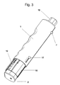
- Fig. 1 shows a device according to the invention in longitudinal section.
- the device consists of a reusable handle 1 and a sensor unit 2, which is designed as a disposable item.
- a drive device is housed, which consists of a piston 8, which is driven by the force of a spring 6 in the housing of the handle 1 down.
- a lower pressure compensation opening 9 and an upper pressure equalization opening 11 ensure unhindered fast-forwarding of the drive device.
- the drive device is actuated by a trigger 7, which can be pressed from the outside on the handset 1 by the user.
- a measuring unit 10 and a display 12 are arranged.
- the sensor unit 2 comprises a microneedle 3, which is attached to an elastic membrane 4, so that when pressure is applied to the membrane 4, the microneedle 3 can be driven into the surface of a skin.
- the sensor unit 2 and the handpiece 1 are brought together via a snap closure 13 with each other. After a proper use of the device, the sensor unit 2 is thrown away, and the handle 1 is used again. For this reason, sensor unit 2 and handle 1 must be separated from each other, which is done with the help of a specially designed discharge edge 14.
- the pneumatic drive device and the sensor unit 2 are now interacting with one another in such a way that, by shutting down the piston 8 via a compressed air space, the elastic membrane 4 and the microneedle 3 attached thereto are pressed downwards into the skin surface.
- the pressure can then escape.
- the pressure on the elastic membrane 4 after, it returns to its original shape, and the microneedle 3 moves upward again, wherein in the sensor unit 2 negative pressure.
- This will Body fluid is sucked from the puncture site, and the body fluid is supplied to the sensor system 5.
- a physical or chemical property change of the sensor system 5 is effected by the constituents of the body fluid to be determined.
- the measuring unit 10 determines a concentration value of the constituents to be determined from these property changes, and they are displayed on the display 12.
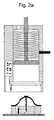
- FIGS. 2a to 2h illustrate different phases of the sampling and analysis in chronological succession.
- FIGS. 2a to 2h are identical representations of the apparatus of FIG. 1. Reference numerals are therefore omitted.
- Fig. 2a shows the initial state of the device with the reusable handle 1 and the sensor unit 2 designed as a disposable article, which is preferably stored in a sterile package before use.
- FIG. 2b shows the sensor unit 2 which is connected to the handpiece 1 by means of the snapped-in snap closure 13.
- Fig. 2c it can be seen that the spring 6 is tensioned in the handle 1, that is, the piston 8 is in its upper position.
- the trigger 7 located at the periphery of the handle 1 keeps the spring 6 from relaxing and advancing the piston 8 downwardly.
- FIG. 2 d shows how the sensor unit 2 used in the handpiece 1 is placed on a skin surface.
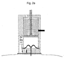
- Fig. 2e represents a so-called. Stechphase.
- the spring 6 By operating the trigger 7, the spring 6 is released, and the piston 8 moves downward. Between the piston 8 and the elastic membrane 4, a compressed air space is built up by the rapid movement of the piston 8. In the handpiece 1, air can penetrate through the upper pressure equalization opening 11.
- the elastic Membrane 4 deforms and microneedle 3 pierces the surface of the skin.
- the air inside the sensor unit 2 is directed out through lateral slots. These slots can be designed as openings of any cross-section and contain closing elements which have a valve function and, for example, open only after exceeding a predetermined pressure difference.
- Fig. 2f the so-called. Suction phase is shown. Through the lower pressure equalization opening 9 escapes compressed air. After reaching the maximum penetration depth, the elastic membrane 4 relaxes again and moves back to the initial state. In this case, a negative pressure is built up within the sensor unit 2 and body fluid is conducted to the sensor system 5. A chemical, biochemical or physical reaction takes place at the sensor system 5. The consequence of this is a physical or chemical property change in the sensor system 5.
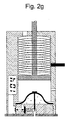
- Fig. 2g shows the actual measurement phase.
- the physical or chemical property changes caused in the sensor system 5 are determined by the measuring unit 10 and then the evaluated measured values are displayed on the display 12.
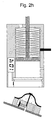
- the sensor unit 2 is removed, which is shown in Fig. 2h.
- An aid in the separation of the sensor unit 2 from the handset 1 represents the discharge edge 14.
- the handpiece 1 is then ready by attaching a further sensor unit 2 for a new use.
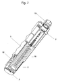
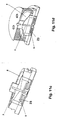
- Fig. 3 shows a perspective view of a device according to the invention for sampling and analysis of body fluids.
- the handle 1 includes a mechanism for pneumatic drive with threaded spindle 18 and spring, which are not visible here.
- a first adjusting member 15 which is here a knob
- the pneumatic drive device is tensioned.
- the trigger 7 can then subsequently the pneumatic drive device are triggered, and there is a compressed gas space inside the handpiece 1.
- This force is exerted on the sensor unit 2.
- the spring on the threaded spindle 18 in the pneumatic drive device spans different degrees.
- the penetration depth can be made variable.
- a second adjusting member 17 the piercing speed can be adjusted.
- a measuring unit 10 which is not visible here, is integrated into the handpiece, which can determine physical or chemical property changes in the sensor system 5. The determined values are then displayed by the display 12.
- electrical energy can be obtained by a corresponding piezoelectric element.
- the generation of electric current can also be done electromagnetically by a small magnet, which has the advantage that then the phase of relaxation of the spring on the threaded spindle 18 can be exploited.
- the electrical energy is recovered in the second way. The recovered electrical energy can then be used, for example, for a control device for the detection of the correct filling with body fluid or for the power supply of self-sufficient sensors.
- FIG. 3 also shows a sleeve 16 for ejecting the sensor unit 2 after use.
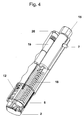
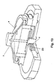
- Fig. 4 gives a view into the interior of the device for sampling and analysis of body fluids.
- the measuring unit 10 is integrated in the handpiece 1, and the sensor unit 2 is mounted.
- the threaded spindle 18 located inside the handpiece 1 with the spring drives the piston 8 downwards after actuation of the trigger 7, compresses the air column located above the elastic membrane 4 in the sensor unit 2 and thus drives the microneedle 3 integrated in the sensor unit 2 downward.
- the power supply is ensured here via batteries 19 in a specially mounted battery compartment 20.
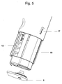
- Fig. 5 illustrates the lower portion of the handle 1 with removed sensor unit 2. It was attached via a snap closure 13, not shown here on the handset 1 and was then by means of 13 fixed to the handle 1 and was then separated by pressure through the sleeve 16 on the discharge edge 14 of the handle 1.
- the sensor unit 2 is usually intended for single use.
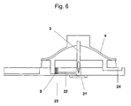
- FIG. 6 shows a schematic representation of the sensor unit 2 in longitudinal section.
- the microneedle 3 fastened in the elastic membrane 4 moves downward under the action of external pressure on the elastic membrane 4 and penetrates into the skin surface, provided that the handpiece 1 with the sensor unit 2 has previously been placed on the skin surface.
- This air escapes for example, a vent channel 24 may be designed as a valve that allows air to penetrate only in one direction, namely from the inside out.
- the microneedle 3 retracts upon release of the external pressure on the elastic membrane 4 back, at the same time in the sensor unit 2, a negative pressure is created, which draws body fluid into the sensor unit 2.
- a capillary 22 this passes directly to a filter assembly 23, is filtered and then comes with the sensor system 5 in touch.
- a sealing ring 21 serves to seal the sensor system 5 against the skin surface.
- the sealing ring 21 may be provided with an adhesive layer to ensure better contact with the skin.
- the underside of the sensor unit 2 can be kept sterile by a removable protective film, which has already been removed here, until use.
- the protective film can remain on the underside of the sensor unit 2 during piercing, but must then be prestressed, so that a sufficiently large opening is formed when piercing.
- Fig. 7 shows another device with cut handpiece 1 and a detailed representation of the trigger mechanism.
- the threaded spindle 18 is released with spring and drives the piston 8 down.
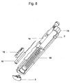
- FIG. 8 shows a device for sampling and analyzing body fluids, which uses optical measuring methods. Especially Here, methods of fluorescence spectrometry are used.
- the measuring unit 10 includes a light source 27 and a photodiode 26 and the required electronics. The power is supplied by means of a battery 19.
- a display 12 On the outside of the handle 1 is a display 12 for displaying the measured values obtained.
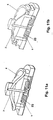
- FIG. 9 is an enlarged view of the sensor unit 2 of the apparatus of FIG. 8.
- An optical fiber block 25 is located on the underside of the handle 1 and is fixedly connected thereto. It directs the excitation light, which originates from the light source 27, directly onto the sensor system 5, intercepts the emitted light again and conducts it to the photodiode 26 located in the measuring unit 10, which is not shown here.
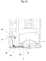
- FIG. 10 shows a further detail view of the sensor unit 2 when using an optical measuring method.
- the excitation light emerges from the light source 27 and is guided via total reflection on a surface 28 via a lens 29 to the sensor system 5.
- the light emitted by the sensor system 5 is conducted via the lens 29 and the totally reflecting surface 28 to the photodiode 26.
- the entire optical arrangement is preferably designed as an integrated optical component.
- FIGS. 11a to 11e show schematic representations of a sensor unit 2 in longitudinal section with different embodiments of the elastic membrane 4.
- the microneedle 3 fixed to the elastic membrane 4 penetrates into the skin surface when external pressure acts on the elastic membrane 4.
- Fig. 11b shows an embodiment of a sensor unit 2, wherein the elastic membrane 4 is engaged in an injection molded part. Upon exertion of external pressure on the elastic membrane 4, the air escapes from the sensor unit 2 laterally by the latching. When relaxation of the elastic membrane 4, a negative pressure is built up in the sensor unit 2, which sucks the body fluid from the skin.
- Fig. 11b shows an embodiment of a sensor unit 2, wherein the elastic membrane 4 is engaged in an injection molded part. Upon exertion of external pressure on the elastic membrane 4, the air escapes from the sensor unit 2 laterally by the latching. When relaxation of the elastic membrane 4, a negative pressure is built up in the sensor unit 2, which sucks the body fluid from the skin.
- Fig. 11b shows an embodiment of a
- the elastic membrane 4 may be held in shape by a spring or a yoke, as shown in Figs. 11d and 11e.
- FIG. 12 shows a plan view of a sensor unit 2 with different sensor systems 5. In this way, detection systems for different analytes are given, wherein either the analytes are detected simultaneously or in a chronologically predetermined order.
- FIG. 13 shows a schematic illustration of a sensor unit 2 for repeated use in section.
- a rotatably latching supply channel for the body fluid, in particular the blood the flow is directed to a sensor system 5 only.
- the supply channel rotates by one grid position and opens the blood channel to the next sensor system 5.
- a sensor unit 2 can also be used for multiple determinations of the same analyte.
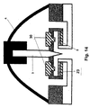
- FIG. 14 is a longitudinal sectional view of a schematic representation of a sensor unit 2 in which the quantitative determination of analytes in the body fluid after the aspiration of the body fluid takes place only after a corresponding processing of the sample.
- substances for sample preparation may be included in the filter assembly 23 .
- reservoirs 30 may be provided which contain substances for preparing the body fluid sample and / or for rinsing, these substances being released by, for example, pressure from valves and diaphragms. In both cases the correct wetting of the sensor matrix can be ensured by a resistance measurement.
- the required amounts of body fluid are low, a largely painless piercing is ensured by the use of microneedles.
- the manufacturing costs are low by manufacturing the sensor unit by injection molding.
- the use is convenient due to the integration of lancing unit and sensor system in a unit for single use and the integration of the measuring unit in the device.
- the principle of integration also ensures maximum hygiene.
- the device has an ergonomic shape and low weight through minimized energy consumption.
Abstract
Description
Gegenstand der Erfindung ist eine Vorrichtung sowie ein entsprechendes Verfahren, mit denen die Probenahme einer Körperflüssigkeit, beispielsweise Blut, sowie die quantitative Analyse darin enthaltener Bestandteile durchgeführt werden kann.The invention relates to a device and a corresponding method, with which the sampling of a body fluid, such as blood, and the quantitative analysis contained therein components can be performed.
In der klinischen Diagnostik ist die Untersuchung von Körperflüssigkeiten, insbesondere von Blut, eine wichtige Methode, um den Gesundheitszustand eines Patienten zu überprüfen. Die häufigsten Untersuchungen werden dabei im Bereich Homecare mit Kapillarblut vom Patienten selbst durchgeführt. Für solche Anwendungen, vor allem für die Bestimmung des Glucosespiegels im Blut, verwenden die Patienten Einstechhilfen, um die Haut leicht zu verletzen und einen kleinen Blutstropfen zu erhalten. Diese Blutprobe wird dann in der Regel auf einen Teststreifen aufgetragen, der mit Hilfe eines Messgeräts ausgewertet wird. Um diese umständliche Prozedur zu vereinfachen und den Schmerz des Patienten zu minimieren, sind bereits zahlreiche Methoden und Technologien entwickelt worden. Dabei wurde versucht, mehrere Arbeitsschritte mit einem einzigen Gerät durchzuführen und außerdem die zur Untersuchung erforderliche Blutmenge zu reduzieren. Letzteres erreicht man zum Beispiel, indem man den Durchmesser der Stechnadel verkleinert und die Einstichtiefe präzise einstellbar macht. Eine dünne Stechnadel bewirkt andererseits nur eine kleine Verletzung der Haut, so dass nur wenig oder gar kein Blut austritt. Durch zusätzliche Hilfsmaßnahmen, wie zum Beispiel Zusammendrücken oder periodische Anregung der Haut an der Einstichstelle, also Vibrationen, sowie durch die Sogwirkung eines erzeugten Unterdrucks lässt sich die Menge des austretenden Blutes vergrößern.In clinical diagnostics, the examination of bodily fluids, especially blood, is an important method for checking the health of a patient. The most frequent examinations are carried out in the field of homecare with capillary blood by the patient himself. For such applications, especially for the determination of blood glucose levels, patients use piercing aids to easily injure the skin and to obtain a small drop of blood. This blood sample is then usually applied to a test strip, which is evaluated by means of a measuring device. To simplify this cumbersome procedure and minimize patient pain, numerous methods and technologies have already been developed. It was attempted to perform several operations with a single device and also reduce the amount of blood required for the investigation. The latter can be achieved, for example, by reducing the diameter of the piercing needle and making the piercing depth precisely adjustable. On the other hand, a thin piercing needle causes only a small injury to the skin, so that little or no blood escapes. Additional remedial measures, such as compression or periodic stimulation of the skin at the injection site, ie vibrations, as well as the suction effect of a generated negative pressure, increase the amount of blood leaving the plant.
Die US 5 505 212 beschreibt eine Vorrichtung, mit der die Blutprobe in eine Kammer aufgenommen wird. Die Kammer besitzt eine flexible und kugelförmige obere Wand, in die eine Stechnadel eingelegt ist. Bei der Anwendung wird die Stechnadel durch die Wand nach unten in die Haut verschoben. Gleichzeitig wird die kugelförmige Wand ebenfalls nach unten gedrückt. Wenn der Druck von oben gelöst wird, kehrt die Vorrichtung zum Ausgangszustand zurück, wobei ein Unterdruck in der Kammer erzeugt wird, der die Blutaufnahme in die Kammer fördert. Die Sogwirkung eines Unterdrucks für das Ansaugen des Blutes ist schon seit Jahren bekannt, siehe hierzu beispielsweise die US 4 653 513. Der Nachteil der in der US 5 505 212 beschriebenen Vorrichtung ist, dass die Kammer und die kugelförmige obere Wand relativ groß bemessen sein müssen, um eine nennenswerte Sogwirkung erzeugen zu können. Infolgedessen wird relativ viel Blut angesaugt, mindestens mehrere Mikroliter, da die Kammer am Ende der Probenahme komplett mit Blut gefüllt ist, und eine geringere Füllmenge an Blut hier nicht einstellbar ist. Zu einer Antriebsmechanik und einer möglicherweise einsetzbaren Messeinrichtung wird kein Hinweis gegeben.US 5 505 212 describes a device with which the blood sample is taken up in a chamber. The chamber has a flexible and spherical Upper wall, in which a piercing needle is inserted. During use, the piercing needle is pushed down the wall through the wall. At the same time, the spherical wall is also pressed down. When the pressure is released from above, the device returns to the initial state, creating a negative pressure in the chamber that promotes blood uptake into the chamber. The suction effect of a negative pressure for the suction of the blood has been known for years, see for example US Pat. No. 4,653,513. The disadvantage of the device described in US Pat. No. 5,505,212 is that the chamber and the spherical upper wall must be dimensioned to be relatively large in order to produce a significant suction effect. As a result, a relatively large amount of blood is drawn in, at least several microliters, since the chamber is completely filled with blood at the end of the sampling, and a smaller amount of blood is not adjustable here. There is no reference to a drive mechanism and a potentially usable measuring device.
In der WO 02/100253 werden eine Vorrichtung und eine Methode beschrieben, mit deren Hilfe Blutproben in einen luftdichten Raum aufgenommen werden. Die Blutaufnahme wird durch Unterdruck begünstigt. Vom Funktionsprinzip her ist das Gerät für relativ große Probenmengen, das heißt 1 bis 5 Mikroliter, ausgelegt. Als weitere Möglichkeit wird die Integration einer Sensorschicht erwähnt.WO 02/100253 describes a device and a method by means of which blood samples are taken up in an airtight space. The blood intake is favored by negative pressure. Functionally, the device is designed for relatively large sample volumes, ie 1 to 5 microliters. Another option mentioned is the integration of a sensor layer.
In der DE 3708031 A1 wird eine in eine Kanüle integrierte Sensorschicht beschrieben. Die Kanüle mit der Sensorschicht wird in eine Saugglocke eingebaut, wo der Unterdruck durch die Heizung und anschließende Kühlung eines Reservoirs hervorgerufen wird. Die optische Messung wird aufwändig mit Hilfe von Lichtleiterfasern gelöst, wobei das Messgerät nicht in die Vorrichtung integriert ist.DE 3708031 A1 describes a sensor layer integrated in a cannula. The cannula with the sensor layer is installed in a suction cup, where the negative pressure is caused by the heating and subsequent cooling of a reservoir. The optical measurement is elaborately solved by means of optical fibers, the meter is not integrated into the device.
Die US 2003/0055326 beschreibt eine Mikronadel für die Aufnahme von Körperflüssigkeiten und die Messung von Analyten. In die Mikronadel, das heißt eine Mikrokanüle mit einem Durchmesser von weniger als 350 Mikrometern, wird eine elektrochemische Sensoreinheit konzentrisch eingesetzt. Die Flüssigkeitsaufnahme wird durch Kapillarkräfte gefördert. Ein derartiges Konzept ist fehleranfällig. Beispielsweise liegt unter der Sensoreinheit in der Mikronadel ein geschlossener Raum, der nicht oder nur zum Teil durch Kapillarkräfte aufgefüllt werden kann, da stets eine Luftblase eingeschlossen bleibt.US 2003/0055326 describes a microneedle for the uptake of body fluids and the measurement of analytes. Into the microneedle, that is a microcannula having a diameter of less than 350 microns, an electrochemical sensor unit is inserted concentrically. The fluid intake is promoted by capillary forces. Such a concept is error-prone. For example, under the sensor unit in the microneedle is a closed space that can not be filled or only partially by capillary forces, as always an air bubble is trapped.
Ein kompaktes Gerät wird in der US 4 637 403 beschrieben. Die Sensoreinheit sitzt auf dem Ende einer Stechnadel oder einer Kapillare auf. Die Auswertung erfolgt mit optischen Methoden. Zur Blutförderung wird ein Vakuum erzeugt. Ein Mikrocomputer übernimmt die Kontrolle und Logistik der Messprozedur und zeigt den Messwert an. Der Nachteil des Konzeptes ist der relativ lange Weg des Blutes bis zum Sensor.A compact device is described in U.S. 4,637,403. The sensor unit sits on the end of a piercing needle or capillary. The evaluation is done with optical methods. To promote blood, a vacuum is created. A microcomputer takes over the control and logistics of the measurement procedure and displays the measured value. The disadvantage of the concept is the relatively long way of the blood to the sensor.
Aus der US 2002/0198444 ist ebenfalls ein kompaktes Messgerät bekannt. Eine elektrische oder optische Sensoreinheit sowie ein Mikrocomputer für die Kontrolle und Logistik sind im Gerät integriert. Die Stechnadel und der bewegliche Teststreifen sind zwei getrennte Einheiten, die in die Lanzettenhalterung eingebaut sind. Das Blut wird hier nicht in das Gerät eingesaugt, sondern der Teststreifen wird zum Blutstropfen geführt. Wegen des komplexen Aufbaus der Lanzettenhalterung und Führung der beweglichen Teile ist die Herstellung dieses Einwegteils aufwändig. Da die Lanzettenhalterung nicht als Reservoir für das Blut vorgesehen ist, können außerdem leicht Funktionsfehler auftreten, zum Beispiel beim Verrutschen des Gerätes auf der Haut.From US 2002/0198444 a compact measuring device is also known. An electrical or optical sensor unit and a microcomputer for the control and logistics are integrated in the device. The piercing needle and the movable test strip are two separate units built into the lancet holder. The blood is not sucked into the device, but the test strip is led to the blood drop. Because of the complex structure of the lancet holder and guidance of the moving parts, the production of this disposable part is expensive. In addition, since the lancet holder is not intended as a reservoir for the blood, it can easily malfunction occur, for example, when slipping the device on the skin.
Seit langer Zeit sind Stechhilfen mit Vakuumunterstützung in verschiedensten Ausführungen bekannt, als Beispiele seien die US 4 653 513, EP 0 622 046, EP 0 838 195, US 6 332 871, US 6 086 545 und die EP 1 060 707 genannt. Die allgemeine Eigenschaft dieser Stechhilfen: Sie funktionieren mit Standardlanzetten oder dazu sehr ähnlichen Lanzetten, und die Integration eines Sensors oder eines Teststreifens ist nicht vorgesehen. In der US 6 332 871 ist lediglich die Möglichkeit erwähnt, dass ein Teststreifen seitlich zur Stechnadel ins Gerät eingeschoben werden kann. Ebenso ist bei diesen Stechhilfen der Raum zum Ansaugen relativ groß, und es muss eine vergleichsweise lange Kolbenbewegung realisiert werden, um ein effizientes Vakuum zu bilden.For a long time lancing devices with vacuum support in various designs have been known, examples being US Pat. Nos. 4,653,513, EP 0 622 046, EP 0 838 195, US Pat. No. 6,332,871, US Pat. No. 6,086,545 and
In der WO 03/094752 und der WO 02/100254 werden die Einstechparameter der Stechnadel elektronisch eingestellt und die Lanzette mit elektromechanischen Bauteilen angesteuert. Es wird die Möglichkeit der Integration von Sensoren und Detektoren erwähnt, jedoch werden diese Lösungen nicht ausführlich dargestellt. Durch die Anwendung von elektronischen Hilfsmitteln könnte der Komfort erhöht werden. Damit verbunden sind jedoch hohe Herstellungskosten, eine aufwändige Energieversorgung und damit ein relativ großes und unhandliches Gerät.In WO 03/094752 and WO 02/100254, the piercing parameters of the piercing needle are adjusted electronically and the lancet is actuated by electromechanical components. The possibility of integration of sensors and detectors is mentioned, but these solutions are not detailed. The use of electronic aids could increase comfort. However, this involves high manufacturing costs, a complex energy supply and thus a relatively large and unwieldy device.
Aus der letzten Zeit sind zahlreiche Erfindungen bekannt, bei denen Stechnadel und Sensor in eine Einheit integriert werden. Eine solche Einheit mit einem nicht näher spezifizierten Testelement ist aus der EP 1 287 785 bekannt, eine Einheit mit einem elektrischen Sensor beschreibt die US 6 607 658, und aus der EP 1 342 448 ist eine Einheit mit optischer Messung bekannt.From the recent time numerous inventions are known in which piercing needle and sensor are integrated into one unit. Such a unit with an unspecified test element is known from
Kompaktgeräte mit integrierter Messeinheit sind Gegenstand der US 6 352 514, EP 1 362 551, EP 1 360 934, EP 1 360 933, WO 03/088834 und WO 02/101359. Diese Geräte nutzen die Kapillarkraft für die Förderung des Blutes zum Sensor. Mit Ausnahme der US 6 352 514 erfolgen Antrieb und Steuerung elektronisch. Obwohl die Handhabung durch die Elektronik einfach ist, sind die elektromechanischen Aktoren störanfälliger als rein mechanisch arbeitende Antriebseinrichtungen.Compact devices with integrated measuring unit are the subject of US Pat. No. 6,352,514,
Die US 6 506 168 und US 6 306 104 beschreiben kompakte Messgeräte mit integrierter Stechhilfe, Sensoreinheit und Messsystem. Die Geräte sind vollelektronisch und verwenden eine Vakuumpumpe für die Förderung des Blutes. Der Nachteil in beiden Fällen ist, dass der Teststreifen und die Lanzette im Gerät getrennt vorliegen und einzeln ausgetauscht werden müssen. Diese umständliche Prozedur verschlechtert den Komfort und erhöht die Fehlerquellen und die Kontaminationsgefahr. Weiterhin verteuert der Einsatz von Pumpen für die Erzeugung eines Vakuums die Herstellungskosten und benötigt eine aufwändige Energieversorgung.The
Die erwähnten Nachteile der Stechhilfen, Sensorsysteme und integrierten Geräte lassen sich wie folgt zusammenfassen: relativ große Mengen an benötigter Körperflüssigkeit, in der Regel ist das Blut, kein schmerzfreies Stechen, hohe Herstellungskosten, mangelnde Integration der einzelnen Komponenten und Verfahrensschritte, mangelhafte Hygiene und wenig Komfort, große und schwere Ausführungsformen durch hohen Energiebedarf.The mentioned disadvantages of the lancing devices, sensor systems and integrated devices can be summarized as follows: relatively large amounts of required body fluid, usually the blood, no pain-free stinging, high manufacturing costs, lack of integration of the individual components and process steps, poor hygiene and little comfort , large and heavy designs due to high energy requirements.
Die Aufgabe der vorliegenden Erfindung besteht darin, eine Vorrichtung sowie ein entsprechendes Verfahren, mit denen die Probenahme einer Körperflüssigkeit, beispielsweise Blut, sowie die quantitative Analyse darin enthaltener Bestandteile durchgeführt werden kann, so zu verbessern, dass der Komfort für einen Benutzer bei geringen Kosten möglichst groß ist.The object of the present invention is to improve a device and a corresponding method with which the sampling of a body fluid, for example blood, as well as the quantitative analysis contained therein components can be performed so that the convenience for a user at low cost possible is great.
Die Aufgabe wird erfindungsgemäß gelöst durch eine Vorrichtung nach dem Anspruch 1 und ein entsprechendes Verfahren.The object is achieved by a device according to
Die erfindungsgemäße Vorrichtung zur Probenahme und Analyse von Körperflüssigkeiten, dabei ist insbesondere an Blut gedacht, umfasst ein Handteil, das eine pneumatische Antriebseinrichtung aufnimmt, und eine Sensoreinheit, die eine Mikronadel, die fest mit einer elastischen Membran verbunden ist, und mindestens ein Sensorsystem enthält. Das Handteil und die Sensoreinheit sind lösbar miteinander verbunden, und die Antriebseinrichtung steht in Wechselwirkung mit der Sensoreinheit auf die Weise, dass die pneumatische Antriebseinrichtung über einen komprimierten Luftraum einen gewissen Druck auf die elastische Membran zum Einstechen der Mikronadel auf eine Hautoberfläche für die Entnahme von Körperflüssigkeit ausübt. Anschließend wird der Druck auf die elastische Membran verringert. Durch das Zurückweichen der Membran in ihre ursprüngliche Form wird im Inneren der Sensoreinheit ein Unterdruck erzeugt und Körperflüssigkeit aus der Einstichstelle zu mindestens einem Sensorsystem transportiert. Im Sensorsystem wird durch die zu bestimmenden Bestandteile der Körperflüssigkeit eine physikalische oder chemische Eigenschaftsänderung des Sensorsystems bewirkt.The device according to the invention for sampling and analyzing body fluids, which is intended in particular for blood, comprises a handpiece which receives a pneumatic drive device and a sensor unit which contains a microneedle fixedly connected to an elastic membrane and at least one sensor system. The handpiece and the sensor unit are detachably connected to each other, and the drive means interacts with the sensor unit in such a way that the pneumatic drive means exerts a certain pressure on the elastic membrane for piercing the microneedle on a skin surface for the removal of body fluid via a compressed air space exercises. Subsequently, the pressure on the elastic membrane is reduced. By the return of the membrane to its original shape, a negative pressure is generated in the interior of the sensor unit and transported body fluid from the puncture site to at least one sensor system. In the sensor system, a physical or chemical property change of the sensor system is caused by the constituents of the body fluid to be determined.
Die erfindungsgemäße Vorrichtung hat zum Vorteil, dass sie vergleichsweise günstig in der Herstellung ist. Die pneumatische Antriebseinrichtung zum Einstechen der Mikronadel und anschließenden Ansaugen von Körperflüssigkeit beruht auf einem einfachen mechanischen Prinzip, ist leicht zu handhaben und wenig störanfällig. Mit einer entsprechenden Bemessung des Innenraums der Sensoreinheit kann die erforderliche Probemenge an Körperflüssigkeit optimal reduziert werden. Die Verwendung einer Mikronadel mit Unterstützung einer Sogwirkung zur Förderung des Blutaustritts halten die Schmerzen dabei gering. Besonders günstig ist die lösbare Verbindung von Handteil und Sensoreinheit, denn dadurch ist es möglich, eine entsprechende Sensoreinheit als sterilen Wegwerfartikel auszuführen, der beispielsweise als Spritzgussteil kostengünstig zu fertigen ist.The device according to the invention has the advantage that it is relatively inexpensive to manufacture. The pneumatic drive device for piercing the microneedle and subsequent aspiration of body fluid is based on a simple mechanical principle, is easy to handle and less susceptible to interference. With a corresponding dimensioning of the interior of the sensor unit, the required sample amount of body fluid can be optimally reduced. The use of a microneedle with the help of a suction effect to promote blood leakage keep the pain low. Particularly favorable is the detachable connection of the handpiece and sensor unit, because this makes it possible to carry out a corresponding sensor unit as a sterile disposable article, which is inexpensive to manufacture, for example, as an injection molded part.
Vorteilhafte Ausführungsformen der Vorrichtung sind Gegenstand der Unteransprüche.Advantageous embodiments of the device are the subject of the dependent claims.
Eine bevorzugte Ausgestaltung der Vorrichtung besteht darin, dass das Handteil eine Messeinheit zur Bestimmung der im Sensorsystem durch Einwirken der zu bestimmenden Bestandteile der Körperflüssigkeit hervorgerufenen physikalischen oder chemischen Eigenschaftsänderungen enthält. Die Messeinheit ermittelt aus diesen Eigenschaftsänderungen den Konzentrationswert eines zu bestimmenden Bestandteils. Vorteilhafterweise erfolgt eine Anzeige auf einem in die Vorrichtung integrierten Display. Auf diese Weise ist es möglich, in einem einzigen Prozess eine Probennahme durchzuführen, den gewünschten Analysewert zu bestimmen und für den Benutzer unmittelbar anzuzeigen. Ebenso ist die Speicherung von Messwerten möglich. In einer speziellen Ausführungsform kann das Ergebnis auch mit einem Transponder oder einem ähnlichen Hilfsmittel an ein zweites Gerät weitergegeben werden. Dieses zweite Gerät kann beispielsweise eine automatische Spritze oder eine Pumpe zur Verabreichung entsprechender Therapeutika wie Insulin sein. Es kann sich hierbei auch um ein Anzeigegerät wie ein Mobiltelefon, eine Armbanduhr, einen PC oder einen PDA handeln.A preferred embodiment of the device consists in that the handpiece contains a measuring unit for determining the physical or chemical property changes caused in the sensor system by the action of the constituents of the body fluid to be determined. The measuring unit determines the concentration value of a constituent to be determined from these property changes. Advantageously, a display is made on a display integrated into the device. In this way, it is possible to perform a sampling in a single process, to determine the desired analysis value and to display it directly to the user. Likewise, the storage of measured values is possible. In a specific embodiment, the result can also be forwarded to a second device with a transponder or a similar aid. This second device may be, for example, an automatic syringe or a pump for administration of appropriate therapeutics such as insulin. It can also be a display device such as a mobile phone, a wristwatch, a PC or a PDA.
Da eine Analyse von Körperflüssigkeiten kostengünstig, zuverlässig und schnell erfolgen soll, sind optische Messverfahren für das Sensorsystem, insbesondere fluoreszenzspektroskopische Messverfahren, von besonderem Vorteil. Bei der Fluoreszenzmessung kann eine minimale Fläche an Sensorsystem verwendet werden, wodurch die Produktion der Sensoreinheiten kostengünstig wird. In einer bevorzugten Ausführung wird als Nachweismethode die FRET-Methode (Fluorescence Resonance Energy Transfer) verwendet.Since an analysis of body fluids should be cost-effective, reliable and fast, optical measurement methods for the sensor system, in particular fluorescence spectroscopic measurement methods, are of particular advantage. In the fluorescence measurement, a minimal amount of sensor system can be used, making the production of the sensor units inexpensive. In a preferred embodiment, the FRET method is called the detection method (F luorescence R esonance E nergy T ransfer) was used.
Die quantitative Auswertung der im Sensorsystem erfolgenden biochemischen Reaktion kann mit optischen Methoden wie UV/Vis-Absorptionsmessung, SPR (Surface Plasmon Resonance), IR-Spektroskopie, Ellipsometrie, Colorimetrie, Fluoreszenzspektrometrie oder auch durch elektrochemische oder sonstige Bestimmungsmethoden erfolgen. Als elektrochemische Messmethoden kommen die Amperometrie und die Coulometrie in Betracht. Andere Methoden arbeiten mit Hilfe von SAW (Surface Acustic Waves), Schwingquarzen, Impedanzmessungen und Cantilevern.The quantitative evaluation of on-the sensor system biochemical reaction can by optical methods such as UV / Vis absorption measurement, SPR (S urface P lasmon R esonance), IR spectroscopy, ellipsometry, colorimetry, fluorescence spectrometry or by electrochemical or other determination methods take place. Electrochemical measurement methods include amperometry and coulometry. Other methods work by using SAW (S urface A Custic W aves), quartz oscillators, impedance measurements and cantilevers.
Eine weitere vorteilhafte Ausführungsform der erfindungsgemäßen Vorrichtung ermöglicht die simultane quantitative Bestimmung mehrerer Bestandteile der Körperflüssigkeit mit demselben oder mit unterschiedlichen Messverfahren. Dazu werden in der Sensoreinheit mehrere Sensorsysteme untergebracht. Auch wenn hierbei eine etwas höhere Blutmenge benötigt wird, ist durch die räumlich enge Verbindung von Entnahmestelle und Sensorsystemen der Blutverbrauch wesentlich kleiner als bei herkömmlichen Methoden, bei denen eine wesentlich größere Blutmenge entnommen und zu räumlich getrennten Messgeräten gebracht werden muss. Bei der Fluoreszenzmessung, insbesondere mit der FRET-Methode, ist es sogar möglich, mehrere Analyten auf derselben Fläche eines Sensorsystems zu messen, da hier durch Messungen bei unterschiedlichen Anregungswellenlängen die verschiedenen Nachweissysteme gemischt auf einem Sensorsystem untergebracht werden können.A further advantageous embodiment of the device according to the invention enables the simultaneous quantitative determination of several constituents of the body fluid with the same or with different measuring methods. For this purpose, several sensor systems are accommodated in the sensor unit. Even if this requires a somewhat larger amount of blood, the spatially close connection between sampling point and sensor systems means that blood consumption is considerably lower than with conventional methods in which a significantly larger amount of blood has to be taken and taken to spatially separate measuring devices. In the fluorescence measurement, in particular with the FRET method, it is even possible to measure a plurality of analytes on the same surface of a sensor system, since the different detection systems can be mixed on a sensor system by measurements at different excitation wavelengths.
Die lösbare Verbindung zwischen dem Handteil und der Sensoreinheit ist in vorteilhafter Weise als schnell einrastende Verbindung ausgestaltet. Das kann beispielsweise eine Steck-, Klemm-, Schnapp-, Schraub- oder Klebeverbindung sein. Wichtig ist dabei in jedem Fall, dass das Lösen und Herstellen der Verbindung schnell und einfach erfolgt und ein Verbinden von Handteil und Sensoreinheit zu einem stabilen Gerät führt.The detachable connection between the handpiece and the sensor unit is designed in an advantageous manner as a quick-locking connection. That can for example, be a plug, clamp, snap, screw or adhesive connection. It is important in any case that the loosening and establishing the connection is quick and easy and connecting the handset and sensor unit leads to a stable device.
In einer weiteren Ausführungsform weist die Sensoreinheit eine Kontrolleinrichtung auf, um die korrekte, insbesondere ausreichende Befüllung, mit Körperflüssigkeit nachzuweisen. So ist es für eine zuverlässige Analyse erforderlich, dass auf jeden Fall eine genügende Menge an Körperflüssigkeit zur Verfügung steht. Die entsprechende Kontrolleinrichtung hierfür kann eine elektrische Widerstandsmesseinheit mit piezoelektrischen oder elektromagnetischen Elementen zur Stromversorgung umfassen. Als ausreichende Befüllung für eine zuverlässige Analyse sind beispielsweise 0.5 µl oder weniger anzusehen. Diese Menge kann der Kontrolleinrichtung als Sollwert vorgegeben sein.In a further embodiment, the sensor unit has a control device in order to detect the correct, in particular sufficient, filling with body fluid. So it is necessary for a reliable analysis that in any case a sufficient amount of body fluid is available. The corresponding control device for this purpose may comprise an electrical resistance measuring unit with piezoelectric or electromagnetic elements for the power supply. As sufficient filling for a reliable analysis, for example 0.5 μl or less are to be regarded. This amount can be specified to the control device as a setpoint.
In einer weiteren Ausführungsform ist vorgesehen, dass das Handteil ein erstes Einstellglied für eine variable Vorgabe der Einstichtiefe der Mikronadel aufweist. Das macht sich besonders dann vorteilhaft bemerkbar, wenn die Einstichtiefe individuell an die Einstichstelle auf der Haut angepasst werden soll. So hängt es stark vom Ort des Einstichs ab, ob die Hautoberfläche dort dicker oder dünner ist und ob die Blutgefäße tiefer oder weniger tief liegen.In a further embodiment it is provided that the handpiece has a first adjusting member for a variable specification of the penetration depth of the microneedle. This is particularly advantageous if the penetration depth is to be individually adapted to the puncture site on the skin. So it depends heavily on the location of the puncture, whether the skin surface is thicker or thinner there and whether the blood vessels are deeper or less deep.
Darüber hinaus ist es möglich, dass ein zweites Einstellglied am Handteil für eine variable Vorgabe der Einstechgeschwindigkeit angebracht ist. Auf diese Weise ist eine individuelle Anpassung möglich, um den Schmerz möglichst gering zu halten. Eine entsprechende Möglichkeit besteht für die variable Vorgabe der Ansauggeschwindigkeit von Körperflüssigkeit durch die Mikronadel mittels eines dritten Einstellglieds.In addition, it is possible that a second adjusting member is attached to the handle for a variable specification of the piercing speed. In this way, an individual adjustment is possible to keep the pain as low as possible. A corresponding possibility exists for the variable specification of the rate of aspiration of body fluid through the microneedle by means of a third setting member.
Für eine Messung der Körperflüssigkeit durch das Sensorsystem kann es vorteilhaft sein, eine Filteranordnung vorzuschalten. Eventuell ist es auch erforderlich, die Körperflüssigkeit vorher besonders aufzubereiten. Das kann geschehen durch Reagenzien und/oder Spüllösungen aus Vorratsbehältern, die ebenfalls vor das Sensorsystem geschaltet werden können und eine Körperflüssigkeit für die Probenahme entsprechend aufbereiten.For a measurement of the body fluid by the sensor system, it may be advantageous to precede a filter arrangement. It may also be necessary to prepare the body fluid in advance. This can be done by reagents and / or rinsing solutions from storage containers, which also can be switched before the sensor system and prepare a body fluid for sampling accordingly.
Das Verfahren zur Probenahme und Analyse von Körperflüssigkeiten besteht aus mehreren Schritten. In einem ersten Schritt übt eine von einem Handteil aufgenommene pneumatische Antriebseinrichtung über einen komprimierten Luftraum Druck auf eine elastische Membran in einer Sensoreinheit zum Einstechen einer an der elastischen Membran befestigten Mikronadel auf eine Hautoberfläche aus, und die Mikronadel dringt in die Hautoberfläche ein. Anschließend wird der Druck auf die elastische Membran verringert. Durch das Zurückweichen der Membran in die ursprüngliche Form wird im Inneren der Sensoreinheit ein Unterdruck erzeugt und Körperflüssigkeit aus der Einstichstelle dadurch zu mindestens einem Sensorsystem transportiert. Im Sensorsystem wird durch die zu bestimmenden Bestandteile der Körperflüssigkeit eine physikalische oder chemische Eigenschaftsänderung des Sensorsystems bewirkt.The procedure for sampling and analyzing body fluids consists of several steps. In a first step, a pneumatic drive device received by a handpiece exerts pressure on an elastic membrane in a sensor unit for piercing a microneedle fastened to the elastic membrane onto a skin surface via a compressed air space, and the microneedle penetrates into the skin surface. Subsequently, the pressure on the elastic membrane is reduced. As a result of the retraction of the membrane into the original shape, a negative pressure is generated in the interior of the sensor unit and body fluid from the puncture site is thereby transported to at least one sensor system. In the sensor system, a physical or chemical property change of the sensor system is caused by the constituents of the body fluid to be determined.
In einem nächsten Schritt bestimmt die Messeinheit aus diesen Eigenschaftsänderungen einen Konzentrationswert des zu bestimmenden Bestandteils und zeigt ihn ggf. auf einem Display an.In a next step, the measuring unit determines a concentration value of the component to be determined from these changes in properties and optionally displays it on a display.
Für ein solches Verfahren wird mit Vorteil eine erfindungsgemäße Vorrichtung verwendet.For such a method, a device according to the invention is advantageously used.
Die Erfindung wird anhand der folgenden Zeichnungen im Einzelnen erläutert.The invention will be explained in more detail with reference to the following drawings.
Es zeigen:
- Fig. 1
- eine schematische Darstellung einer erfindungsgemäßen Vorrichtung in einem Längsschnitt,
- Fig. 2a bis 2h
- eine Probenahme und Analyse von Körperflüssigkeiten mit der Vorrichtung aus Fig. 1 in acht zeitlich aufeinander folgenden Phasen,
- Fig. 3
- eine perspektivische Ansicht auf eine erfindungsgemäße Vorrichtung zur Probenahme und Analyse von Körperflüssigkeiten,
- Fig. 4
- eine Darstellung der Vorrichtung zur Probenahme und Analyse von Körperflüssigkeiten mit aufgeschnittenem Handteil,
- Fig. 5
- den unteren Bereich des Handteils mit abgenommener Sensoreinheit,
- Fig. 6
- eine schematische Darstellung einer Sensoreinheit im Längsschnitt,
- Fig. 7
- eine weitere Darstellung der Vorrichtung mit aufgeschnittenem Handteil und eine detaillierte Wiedergabe des Auslösemechanismus,
- Fig. 8
- eine Vorrichtung zur Probenahme und Analyse von Körperflüssigkeiten, die mit optischen Messverfahren arbeitet,
- Fig. 9
- eine vergrößerte Ansicht der Sensoreinheit der Vorrichtung aus Fig. 8,
- Fig. 10
- eine weitere Detailansicht der Sensoreinheit bei Anwendung eines optischen Messverfahrens,
- Fig. 11a bis 11e
- mehrere schematische Darstellungen von Sensoreinheiten im Längsschnitt mit verschiedenen Ausgestaltungen der elastischen Membran,
- Fig. 12
- eine Draufsicht auf eine Sensoreinheit mit verschiedenen Sensorsystemen,
- Fig. 13
- eine schematische Darstellung einer Sensoreinheit für den mehrmaligen Gebrauch im Schnitt,
- Fig. 14
- eine schematische Darstellung einer Sensoreinheit im Längsschnitt mit einer zusätzlichen Filteranordnung und Vorratsbehältern.
- Fig. 1
- a schematic representation of a device according to the invention in a longitudinal section,
- Fig. 2a to 2h
- a sampling and analysis of body fluids with the device of FIG. 1 in eight temporally successive phases,
- Fig. 3
- a perspective view of an inventive device for sampling and analysis of body fluids,
- Fig. 4
- a representation of the device for sampling and analysis of body fluids with cut handpiece,
- Fig. 5
- the lower part of the handpiece with removed sensor unit,
- Fig. 6
- a schematic representation of a sensor unit in longitudinal section,
- Fig. 7
- a further illustration of the device with a cut open handpiece and a detailed representation of the triggering mechanism,
- Fig. 8
- a body fluid sampling and analysis device using optical measuring techniques,
- Fig. 9
- an enlarged view of the sensor unit of the device of Fig. 8,
- Fig. 10
- a further detail view of the sensor unit using an optical measuring method,
- Fig. 11a to 11e
- several schematic representations of sensor units in longitudinal section with different embodiments of the elastic membrane,
- Fig. 12
- a top view of a sensor unit with different sensor systems,
- Fig. 13
- a schematic representation of a sensor unit for repeated use in section,
- Fig. 14
- a schematic representation of a sensor unit in longitudinal section with an additional filter assembly and storage containers.
Fig. 1 stellt eine erfindungsgemäße Vorrichtung im Längsschnitt dar. Die Vorrichtung besteht aus einem wieder verwendbaren Handteil 1 und einer Sensoreinheit 2, die als Wegwerfartikel ausgebildet ist. In dem Handteil 1 ist eine Antriebseinrichtung untergebracht, die aus einem Kolben 8 besteht, der durch die Kraft einer Feder 6 in dem Gehäuse des Handteils 1 nach unten getrieben wird. Eine untere Druckausgleichsöffnung 9 und eine obere Druckausgleichsöffnung 11 sorgen für ein ungehindertes Vorschnellen der Antriebseinrichtung. Die Antriebseinrichtung wird betätigt durch einen Auslöser 7, der von außen am Handteil 1 vom Benutzer eingedrückt werden kann. Des Weiteren sind in dem Handteil 1 eine Messeinheit 10 sowie ein Display 12 angeordnet. Die Sensoreinheit 2 umfasst eine Mikronadel 3, welche an einer elastischen Membran 4 befestigt ist, so dass bei Druck auf die Membran 4 die Mikronadel 3 in die Oberfläche einer Haut getrieben werden kann. Die Sensoreinheit 2 und das Handteil 1 werden über einen Schnappverschluss 13 miteinander in Verbindung gebracht. Nach einer bestimmungsgemäßen Benutzung der Vorrichtung wird die Sensoreinheit 2 weggeworfen, und das Handteil 1 wird wieder verwendet. Aus diesem Grund müssen Sensoreinheit 2 und Handteil 1 voneinander getrennt werden, was mit Hilfe einer eigens dafür vorgesehenen Abwurfkante 14 erfolgt. Die pneumatische Antriebseinrichtung und die Sensoreinheit 2 stehen nun in der Weise miteinander in Wechselwirkung, dass durch Herunterfahren des Kolbens 8 über einen komprimierten Luftraum die elastische Membran 4 sowie die daran befestigte Mikronadel 3 nach unten in die Hautoberfläche gedrückt werden. Durch die untere Druckausgleichsöffnung 9 kann anschließend der Überdruck entweichen. Dadurch lässt der Druck auf die elastische Membran 4 nach, sie kehrt in ihre Ausgangsform zurück, und die Mikronadel 3 bewegt sich wieder nach oben, wobei in der Sensoreinheit 2 Unterdruck entsteht. Dadurch wird Körperflüssigkeit aus der Einstichstelle angesaugt, und die Körperflüssigkeit wird dem Sensorsystem 5 zugeführt. Im Sensorsystem 5 wird durch die zu bestimmenden Bestandteile der Körperflüssigkeit eine physikalische oder chemische Eigenschaftsänderung des Sensorsystems 5 bewirkt. Die Messeinheit 10 bestimmt aus diesen Eigenschaftsänderungen einen Konzentrationswert der zu bestimmenden Bestandteile, und sie werden auf dem Display 12 angezeigt.Fig. 1 shows a device according to the invention in longitudinal section. The device consists of a
Eine Probenahme und anschließende Analyse von Körperflüssigkeit mit der Vorrichtung aus Fig. 1 wird anhand der acht Fig. 2a bis 2h veranschaulicht. Die Fig. 2a bis 2h stellen zeitlich aufeinander folgend verschiedene Phasen der Probenahme und Analyse dar. Die Fig. 2a bis 2h sind identische Wiedergaben der Vorrichtung aus Fig. 1. Auf Bezugszeichen wird deshalb verzichtet.Sampling and subsequent analysis of body fluid with the apparatus of Fig. 1 will be illustrated with reference to Figs. 2a-2h. FIGS. 2a to 2h illustrate different phases of the sampling and analysis in chronological succession. FIGS. 2a to 2h are identical representations of the apparatus of FIG. 1. Reference numerals are therefore omitted.
Die Fig. 2a zeigt den Ausgangszustand der Vorrichtung mit dem wieder verwendbaren Handteil 1 und der als Wegwerfartikel ausgebildeten Sensoreinheit 2, die vor Gebrauch vorzugsweise in einer sterilen Verpackung aufbewahrt wird.Fig. 2a shows the initial state of the device with the
Die Fig. 2b zeigt die Sensoreinheit 2, die mittels des eingeschnappten Schnappverschlusses 13 mit dem Handteil 1 verbunden ist.FIG. 2b shows the
In der Fig. 2c ist erkennbar, dass die Feder 6 im Handteil 1 gespannt wird, d.h., der Kolben 8 befindet sich in seiner oberen Position. Der am Umfang des Handteils 1 befindliche Auslöser 7 hält die Feder 6 davon ab, sich zu entspannen und den Kolben 8 nach unten voranzutreiben.In Fig. 2c it can be seen that the
Die Fig. 2d stellt dar, wie die im Handteil 1 eingesetzte Sensoreinheit 2 auf eine Hautoberfläche aufgesetzt wird.FIG. 2 d shows how the
Die Fig. 2e stellt eine sog. Stechphase dar. Durch Betätigung des Auslösers 7 wird die Feder 6 entspannt, und der Kolben 8 bewegt sich nach unten. Zwischen dem Kolben 8 und der elastischen Membran 4 wird durch die schnelle Bewegung des Kolbens 8 ein komprimierter Luftraum aufgebaut. Im Handteil 1 kann Luft durch die obere Druckausgleichsöffnung 11 eindringen. Die elastische Membran 4 verformt sich, und die Mikronadel 3 sticht durch die Hautoberfläche. Die Luft innerhalb der Sensoreinheit 2 wird durch seitliche Schlitze nach außen geleitet. Diese Schlitze können als Öffnungen mit beliebigem Querschnitt ausgeführt sein und Schließelemente enthalten, die eine Ventilfunktion aufweisen und sich beispielsweise erst nach Überschreiten einer vorgegebenen Druckdifferenz öffnen.Fig. 2e represents a so-called. Stechphase. By operating the
In der Fig. 2f ist die sog. Saugphase dargestellt. Durch die untere Druckausgleichsöffnung 9 entweicht komprimierte Luft. Nach Erreichen der maximalen Einstichtiefe entspannt sich die elastische Membran 4 wieder und bewegt sich in den Ausgangszustand zurück. Dabei wird ein Unterdruck innerhalb der Sensoreinheit 2 aufgebaut und Körperflüssigkeit zu dem Sensorsystem 5 geleitet. Eine chemische, biochemische oder physikalische Reaktion findet an dem Sensorsystem 5 statt. Die Folge davon ist eine physikalische oder chemische Eigenschaftsänderung im Sensorsystem 5.In Fig. 2f the so-called. Suction phase is shown. Through the lower
Die Fig. 2g zeigt die eigentliche Messphase. Die im Sensorsystem 5 hervorgerufenen physikalischen oder chemischen Eigenschaftsänderungen werden durch die Messeinheit 10 bestimmt und anschließend die ausgewerteten Messwerte im Display 12 angezeigt.Fig. 2g shows the actual measurement phase. The physical or chemical property changes caused in the
Nach Beendigung der Probenahme und Analyse wird die Sensoreinheit 2 entfernt, was in der Fig. 2h dargestellt ist. Eine Hilfe beim Abtrennen der Sensoreinheit 2 vom Handteil 1 stellt die Abwurfkante 14 dar. Das Handteil 1 ist danach durch Aufstecken einer weiteren Sensoreinheit 2 für einen neuen Einsatz bereit.After completion of the sampling and analysis, the
Die Fig. 3 stellt eine perspektivische Ansicht auf eine erfindungsgemäße Vorrichtung zur Probenahme und Analyse von Körperflüssigkeiten dar. Das Handteil 1 enthält einen Mechanismus zum pneumatischen Antrieb mit Gewindespindel 18 und Feder, die hier nicht erkennbar sind. Durch Drehen eines ersten Einstellglieds 15, das ist hier ein Drehknopf, wird die pneumatische Antriebseinrichtung gespannt. Durch Drücken des Auslösers 7 kann dann anschließend die pneumatische Antriebseinrichtung ausgelöst werden, und es entsteht ein komprimierter Gasraum im Inneren des Handteils 1. Dadurch wird Kraft auf die Sensoreinheit 2 ausgeübt. Je nachdem, wie weit der Drehknopf 15 gedreht wird, spannt sich die Feder an der Gewindespindel 18 in der pneumatischen Antriebseinrichtung unterschiedlich stark. Damit kann die Einstichtiefe variabel gestaltet werden. Durch ein zweites Einstellglied 17 kann die Einstechgeschwindigkeit eingestellt werden. Außerdem ist eine Messeinheit 10, die hier nicht sichtbar ist, in das Handteil integriert, die physikalische oder chemische Eigenschaftsänderungen im Sensorsystem 5 bestimmen kann. Die bestimmten Werte werden anschließend vom Display 12 angezeigt. Beim Spannen der pneumatischen Antriebseinrichtung kann elektrische Energie durch ein entsprechendes Piezoelement gewonnen werden. Die Erzeugung von elektrischem Strom kann aber auch elektromagnetisch durch einen kleinen Magneten erfolgen, was den Vorteil hat, dass dann die Phase des Entspannens der Feder an der Gewindespindel 18 ausgenutzt werden kann. Vorzugsweise wird die elektrische Energie auf die als zweite genannte Weise gewonnen. Die gewonnene elektrische Energie kann dann zum Beispiel für eine Kontrolleinrichtung zum Nachweis der korrekten Befüllung mit Körperflüssigkeit oder für die Energieversorgung von autarken Sensoren verwendet werden. In der Fig. 3 ist außerdem eine Hülse 16 zum Abwurf der Sensoreinheit 2 nach Gebrauch dargestellt.Fig. 3 shows a perspective view of a device according to the invention for sampling and analysis of body fluids. The
Die Fig. 4 gibt eine Ansicht ins Innere der Vorrichtung zur Probenahme und Analyse von Körperflüssigkeiten frei. Die Messeinheit 10 ist im Handteil 1 integriert, und die Sensoreinheit 2 ist aufgesetzt. Die im Inneren des Handteils 1 liegende Gewindespindel 18 mit der Feder treibt nach Betätigen des Auslösers 7 den Kolben 8 nach unten, drückt dabei die über der elastischen Membran 4 in der Sensoreinheit 2 befindliche Luftsäule zusammen und treibt damit die in die Sensoreinheit 2 integrierte Mikronadel 3 nach unten. Die Energieversorgung wird hier über Batterien 19 in einem eigens dafür angebrachten Batteriefach 20 gewährleistet.Fig. 4 gives a view into the interior of the device for sampling and analysis of body fluids. The measuring
Die Fig. 5 stellt den unteren Bereich des Handteils 1 mit abgenommener Sensoreinheit 2 dar. Sie war über einen hier nicht dargestellten Schnappverschluss 13 am Handteil 1 befestigt und wurde anschließend mittels 13 am Handteil 1 befestigt und wurde anschließend mittels Druck durch die Hülse 16 auf die Abwurfkante 14 vom Handteil 1 getrennt. Die Sensoreinheit 2 ist üblicherweise für den einmaligen Gebrauch bestimmt.Fig. 5 illustrates the lower portion of the
Die Fig. 6 zeigt eine schematische Darstellung der Sensoreinheit 2 im Längsschnitt. Die in der elastischen Membran 4 befestigte Mikronadel 3 bewegt sich bei Einwirkungen von äußerem Druck auf die elastische Membran 4 nach unten und dringt in die Hautoberfläche ein, sofern das Handteil 1 mit der Sensoreinheit 2 vorher auf die Hautoberfläche aufgesetzt wurde. Dabei entweicht Luft, wobei zum Beispiel ein Entlüftungskanal 24 wie ein Ventil ausgeführt sein kann, das ein Durchdringen von Luft nur in eine Richtung, nämlich von innen nach außen, zulässt. Die Mikronadel 3 zieht sich beim Nachlassen des äußeren Drucks auf die elastische Membran 4 wieder zurück, wobei gleichzeitig in der Sensoreinheit 2 ein Unterdruck entsteht, welcher Körperflüssigkeit in die Sensoreinheit 2 zieht. Durch eine Kapillare 22 gelangt diese direkt auf eine Filteranordnung 23, wird gefiltert und kommt danach mit dem Sensorsystem 5 in Berührung. Ein Abdichtring 21 dient zur Abdichtung des Sensorsystems 5 gegenüber der Hautoberfläche. In einer speziellen Ausführungsform kann der Abdichtring 21 mit einer Klebeschicht versehen sein, um einen besseren Kontakt mit der Haut zu gewährleisten. Die Unterseite der Sensoreinheit 2 kann durch eine abziehbare Schutzfolie, die hier bereits entfernt wurde, bis zur Verwendung steril gehalten werden. Bei einer anderen Ausführungsform kann die Schutzfolie beim Stechen auf der Unterseite der Sensoreinheit 2 verbleiben, muss dann aber vorgespannt sein, damit beim Durchstechen eine ausreichend große Öffnung entsteht.FIG. 6 shows a schematic representation of the
Die Fig. 7 stellt eine weitere Vorrichtung mit aufgeschnittenem Handteil 1 und einer detaillierten Wiedergabe des Auslösemechanismus dar. Durch Drücken des Auslösers 7 wird die Gewindespindel 18 mit Feder freigegeben und treibt den Kolben 8 nach unten.Fig. 7 shows another device with
In der Fig. 8 ist eine Vorrichtung zur Probenahme und Analyse von Körperflüssigkeiten zu sehen, die mit optischen Messverfahren arbeitet. Insbesondere werden hier Methoden der Fluoreszenzspektrometrie verwendet. Die Messeinheit 10 beinhaltet eine Lichtquelle 27 und eine Photodiode 26 sowie die erforderliche Elektronik. Die Stromversorgung erfolgt mit Hilfe einer Batterie 19. An der Außenseite des Handteils 1 befindet sich ein Display 12 zur Anzeige der gewonnenen Messwerte.FIG. 8 shows a device for sampling and analyzing body fluids, which uses optical measuring methods. Especially Here, methods of fluorescence spectrometry are used. The measuring
Die Fig. 9 ist eine vergrößerte Ansicht der Sensoreinheit 2 der Vorrichtung aus Fig. 8. Ein Lichtleiterblock 25 befindet sich an der Unterseite des Handteils 1 und ist fest mit diesem verbunden. Er leitet das Anregungslicht, welches aus der Lichtquelle 27 stammt, direkt auf das Sensorsystem 5, fängt das emittierte Licht wieder auf und leitet es zu der in der Messeinheit 10 befindlichen Photodiode 26, die hier nicht abgebildet ist.FIG. 9 is an enlarged view of the
Die Fig. 10 zeigt eine weitere Detailansicht der Sensoreinheit 2 bei Anwendung eines optischen Messverfahrens. Das Anregungslicht tritt aus der Lichtquelle 27 aus und wird über Totalreflektion an einer Oberfläche 28 über eine Linse 29 auf das Sensorsystem 5 geführt. Das vom Sensorsystem 5 emittierte Licht wird über die Linse 29 und die total reflektierende Oberfläche 28 zu der Photodiode 26 geleitet. Die gesamte optische Anordnung ist vorzugsweise als integriertes optisches Bauteil ausgeführt.FIG. 10 shows a further detail view of the
Die Fig. 11a bis 11e zeigen schematische Darstellungen einer Sensoreinheit 2 im Längsschnitt mit verschiedenen Ausgestaltungen der elastischen Membran 4. In allen Fällen dringt die an der elastischen Membran 4 befestigte Mikronadel 3 bei Einwirkung von äußerem Druck auf die elastische Membran 4 in die Hautoberfläche ein. Die Fig. 11b zeigt eine Ausführung einer Sensoreinheit 2, bei der die elastische Membran 4 in ein Spritzgussteil eingerastet ist. Bei Ausübung von äußerem Druck auf die elastische Membran 4 entweicht die Luft aus der Sensoreinheit 2 seitlich durch die Einrastung. Bei Entspannung der elastischen Membran 4 wird in der Sensoreinheit 2 ein Unterdruck aufgebaut, der die Körperflüssigkeit aus der Haut saugt. Eine weitere Ausführungsform ist in der Fig. 11c dargestellt, bei der eine ebene elastische Membran 4 und eine entsprechende Vertiefung verwendet werden, die eine Variation des Volumens analog zur elastischen Membran 4 der anderen Sensoreinheiten 2 ermöglichen. Die elastische Membran 4 kann alternativ durch eine Feder oder einen Bügel in Form gehalten werden, wie es in den Fig. 11d und 11e dargestellt ist.FIGS. 11a to 11e show schematic representations of a
In der Fig. 12 ist eine Draufsicht auf eine Sensoreinheit 2 mit verschiedenen Sensorsystemen 5 dargestellt. Auf diese Weise sind Nachweissysteme für unterschiedliche Analyten gegeben, wobei entweder die Analyten gleichzeitig oder in einer zeitlich vorgebbaren Reihenfolge nachgewiesen werden.FIG. 12 shows a plan view of a
In der Fig. 13 ist eine schematische Darstellung einer Sensoreinheit 2 für den mehrmaligen Gebrauch im Schnitt angegeben. Durch einen drehbar einrastenden Zuführungskanal für die Körperflüssigkeit, insbesondere das Blut, wird der Fluss jeweils nur auf ein Sensorsystem 5 geleitet. Nach erfolgter Messung des Analyten dreht sich der Zuführungskanal um eine Rasterstellung weiter und öffnet den Blutkanal zum nächsten Sensorsystem 5. Auf diese Weise ist eine Sensoreinheit 2 auch für mehrmalige Bestimmungen des gleichen Analyten einsetzbar.FIG. 13 shows a schematic illustration of a
In der Fig. 14 ist eine schematische Darstellung einer Sensoreinheit 2 im Längsschnitt zu sehen, in der die nach dem Ansaugen der Körperflüssigkeit erfolgende quantitative Bestimmung von Analyten in der Körperflüssigkeit erst nach einer entsprechenden Aufarbeitung der Probe erfolgt. In der Filteranordnung 23 können Substanzen zur Probenvorbereitung enthalten sein. Zusätzlich können Vorratsbehälter 30 vorgesehen sein, die Substanzen zur Vorbereitung der Probe der Körperflüssigkeit und/oder zum Spülen enthalten, wobei diese Substanzen, beispielsweise durch Einwirkung von Druck über Ventile und Membranen, freigesetzt werden. In beiden Fällen kann durch eine Widerstandsmessung das korrekte Benetzen der Sensormatrix sichergestellt werden.FIG. 14 is a longitudinal sectional view of a schematic representation of a
Die mit der erfindungsgemäßen Vorrichtung und ihren vorteilhaften Ausführungsformen sowie mit dem Verfahren hierzu durchführbare Probennahme und Analyse von Körperflüssigkeiten hat gegenüber den bisher bekannten Methoden folgende Vorteile:The sampling and analysis of body fluids which can be carried out with the apparatus according to the invention and its advantageous embodiments and with the method for this purpose have the following advantages over the previously known methods:
Die benötigten Mengen an Körperflüssigkeit sind gering, ein weitgehend schmerzfreies Stechen wird durch Einsatz von Mikronadeln gewährleistet. Die Herstellungskosten sind durch Fertigung der Sensoreinheit im Spritzgussverfahren gering. Die Benutzung ist komfortabel durch die Integration von Stecheinheit und Sensorsystem in einer Einheit zum einmaligen Gebrauch sowie die Integration der Messeinheit in die Vorrichtung. Das Prinzip der Integration stellt darüber hinaus maximale Hygiene sicher. Die Vorrichtung hat eine ergonomische Gestalt und ein geringes Gewicht durch minimierten Energieverbrauch.The required amounts of body fluid are low, a largely painless piercing is ensured by the use of microneedles. The manufacturing costs are low by manufacturing the sensor unit by injection molding. The use is convenient due to the integration of lancing unit and sensor system in a unit for single use and the integration of the measuring unit in the device. The principle of integration also ensures maximum hygiene. The device has an ergonomic shape and low weight through minimized energy consumption.
Claims (29)
Priority Applications (5)
| Application Number | Priority Date | Filing Date | Title |
|---|---|---|---|
| EP04002436A EP1621132B1 (en) | 2003-06-27 | 2004-02-04 | Device and method for sampling and analysing body fluids |
| EP04010983A EP1529488A1 (en) | 2003-06-27 | 2004-05-08 | Device and method for sampling and analysing body fluids |
| EP04740318A EP1680022A1 (en) | 2003-06-27 | 2004-06-25 | Device and method for drawing a sample and analyzing body fluids |
| PCT/EP2004/006908 WO2005000118A1 (en) | 2003-06-27 | 2004-06-25 | Device and method for drawing a sample and analyzing body fluids |
| US11/578,758 US20070213638A1 (en) | 2003-06-27 | 2004-06-25 | Device and Method for Drawing a Sample and Analyzing Body |
Applications Claiming Priority (2)
| Application Number | Priority Date | Filing Date | Title |
|---|---|---|---|
| EP03014772A EP1522260A1 (en) | 2003-06-27 | 2003-06-27 | Device for blood sampling and simultaneous quantitative determination of blood analytes |
| EP04002436A EP1621132B1 (en) | 2003-06-27 | 2004-02-04 | Device and method for sampling and analysing body fluids |
Publications (2)
| Publication Number | Publication Date |
|---|---|
| EP1621132A1 true EP1621132A1 (en) | 2006-02-01 |
| EP1621132B1 EP1621132B1 (en) | 2007-03-07 |
Family
ID=33553810
Family Applications (2)
| Application Number | Title | Priority Date | Filing Date |
|---|---|---|---|
| EP04002436A Expired - Lifetime EP1621132B1 (en) | 2003-06-27 | 2004-02-04 | Device and method for sampling and analysing body fluids |
| EP04740318A Withdrawn EP1680022A1 (en) | 2003-06-27 | 2004-06-25 | Device and method for drawing a sample and analyzing body fluids |
Family Applications After (1)
| Application Number | Title | Priority Date | Filing Date |
|---|---|---|---|
| EP04740318A Withdrawn EP1680022A1 (en) | 2003-06-27 | 2004-06-25 | Device and method for drawing a sample and analyzing body fluids |
Country Status (3)
| Country | Link |
|---|---|
| US (1) | US20070213638A1 (en) |
| EP (2) | EP1621132B1 (en) |
| WO (1) | WO2005000118A1 (en) |
Families Citing this family (34)
| Publication number | Priority date | Publication date | Assignee | Title |
|---|---|---|---|---|
| GB0420256D0 (en) | 2004-09-13 | 2004-10-13 | Cassells John M | Method and apparatus for sampling and analysis of fluids |
| DE102005005017A1 (en) * | 2005-02-03 | 2006-08-17 | Roche Diagnostics Gmbh | Electromechanical lancing device for obtaining liquid samples |
| KR100716015B1 (en) * | 2005-06-08 | 2007-05-08 | 유재천 | lancet device and method for sampling and injecting blood using same |
| WO2007001001A1 (en) * | 2005-06-27 | 2007-01-04 | National Institute Of Advanced Industrial Science And Technology | Needle integrating biosensor |
| GB0605003D0 (en) * | 2006-03-13 | 2006-04-19 | Microsample Ltd | Method and apparatus for piercing the skin and delivery or collection of liquids |
| FR2929135A1 (en) * | 2008-03-31 | 2009-10-02 | Commissariat Energie Atomique | DEVICE FOR ALIQUOTAGE AND EXEMPTION OF A LIQUID |
| US20110172510A1 (en) * | 2010-01-13 | 2011-07-14 | Seventh Sense Biosystems, Inc. | Rapid delivery and/or withdrawal of fluids |
| US8827971B2 (en) | 2011-04-29 | 2014-09-09 | Seventh Sense Biosystems, Inc. | Delivering and/or receiving fluids |
| WO2012018486A2 (en) | 2010-07-26 | 2012-02-09 | Seventh Sense Biosystems, Inc. | Rapid delivery and/or receiving of fluids |
| WO2010101620A2 (en) | 2009-03-02 | 2010-09-10 | Seventh Sense Biosystems, Inc. | Systems and methods for creating and using suction blisters or other pooled regions of fluid within the skin |
| WO2010109461A1 (en) * | 2009-03-23 | 2010-09-30 | Sindolor Medical Ltd. | A painlessly hand-held apparatus useful for piercing, detection and quantization of an analyte and methods thereof |
| EP3243435A1 (en) * | 2010-01-13 | 2017-11-15 | Seventh Sense Biosystems, Inc. | Sampling device interfaces |
| WO2011094573A1 (en) | 2010-01-28 | 2011-08-04 | Seventh Sense Biosystems, Inc. | Monitoring or feedback systems and methods |
| GB201007007D0 (en) * | 2010-04-27 | 2010-06-09 | Smith Maria | Foetal blood sampling probe |
| WO2011163347A2 (en) | 2010-06-23 | 2011-12-29 | Seventh Sense Biosystems, Inc. | Sampling devices and methods involving relatively little pain |
| JP2013538069A (en) | 2010-07-16 | 2013-10-10 | セブンス センス バイオシステムズ,インコーポレーテッド | Low pressure environment for fluid transfer devices |
| WO2012021801A2 (en) | 2010-08-13 | 2012-02-16 | Seventh Sense Biosystems, Inc. | Systems and techniques for monitoring subjects |
| US8808202B2 (en) | 2010-11-09 | 2014-08-19 | Seventh Sense Biosystems, Inc. | Systems and interfaces for blood sampling |
| US8647357B2 (en) | 2011-02-05 | 2014-02-11 | Birch Narrows Development Llc | Lancet device with flexible cover |
| US20120271125A1 (en) * | 2011-04-11 | 2012-10-25 | Seventh Sense Biosystems, Inc. | Devices and methods for delivery and/or withdrawal of fluids and preservation of withdrawn fluids |
| WO2012149155A1 (en) * | 2011-04-29 | 2012-11-01 | Seventh Sense Biosystems, Inc. | Systems and methods for collecting fluid from a subject |
| CA2833175A1 (en) | 2011-04-29 | 2012-11-01 | Seventh Sense Biosystems, Inc. | Devices and methods for collection and/or manipulation of blood spots or other bodily fluids |
| US20130158468A1 (en) | 2011-12-19 | 2013-06-20 | Seventh Sense Biosystems, Inc. | Delivering and/or receiving material with respect to a subject surface |
| WO2013112877A1 (en) | 2012-01-25 | 2013-08-01 | Tasso, Inc. | Handheld device for drawing, collecting, and analyzing bodily fluid |
| US9237866B2 (en) | 2013-04-29 | 2016-01-19 | Birch Narrows Development, LLC | Blood glucose management |
| KR102315189B1 (en) * | 2014-06-07 | 2021-10-19 | 아스실리온 에이비 | A microfabricated sensor and a method of detecting a component in bodily fluid |
| EP4338669A2 (en) | 2014-08-01 | 2024-03-20 | Tasso, Inc. | Systems for gravity-enhanced microfluidic collection, handling and transferring of fluids |
| US9730625B2 (en) * | 2015-03-02 | 2017-08-15 | Verily Life Sciences Llc | Automated blood sampling device |
| US10765361B2 (en) | 2015-03-02 | 2020-09-08 | Verily Life Sciences Llc | Automated sequential injection and blood draw |
| US10426390B2 (en) * | 2015-12-21 | 2019-10-01 | Tasso, Inc. | Devices, systems and methods for actuation and retraction in fluid collection |
| US10136848B2 (en) * | 2016-05-20 | 2018-11-27 | Winnoz Technology, Inc. | Device and system of blood collection, and method thereof |
| US20200085414A1 (en) | 2018-09-14 | 2020-03-19 | Tasso, Inc. | Bodily fluid collection devices and related methods |
| JP2022507378A (en) * | 2018-11-13 | 2022-01-18 | タッソ インコーポレイテッド | Body fluid collection devices including electronic devices and related systems and methods |
| GB2622865A (en) * | 2022-09-30 | 2024-04-03 | Cambridge Entpr Ltd | A housing for sample collection |
Citations (7)
| Publication number | Priority date | Publication date | Assignee | Title |
|---|---|---|---|---|
| US4637403A (en) * | 1985-04-08 | 1987-01-20 | Garid, Inc. | Glucose medical monitoring system |
| DE3708031A1 (en) * | 1986-03-20 | 1987-11-12 | Wolfgang Dr Med Wagner | Measurement device or induction device with measurement device, or device for material recovery for a measurement device for metabolic states in the blood by puncturing under reduced pressure in a suction cup with displacement of the measurement zone outside the tip region of the puncturing device |
| US5505212A (en) * | 1991-06-21 | 1996-04-09 | Novo Nordisk A/S | Blood sampler |
| WO2002100252A2 (en) * | 2001-06-12 | 2002-12-19 | Pelikan Technologies, Inc. | Blood sampling apparatus and method |
| WO2002100251A2 (en) * | 2001-06-12 | 2002-12-19 | Pelikan Technologies, Inc. | Self optimizing lancing device with adaptation means to temporal variations in cutaneous properties |
| US20020198444A1 (en) * | 1999-12-13 | 2002-12-26 | Takatoshi Uchigaki | Body fluid measuring apparatus with lancet and lancet holder used for the measuring apparatus |
| US20030088191A1 (en) * | 2001-06-12 | 2003-05-08 | Freeman Dominique M. | Blood sampling device with diaphragm actuated lancet |
Family Cites Families (6)
| Publication number | Priority date | Publication date | Assignee | Title |
|---|---|---|---|---|
| US4653513A (en) | 1985-08-09 | 1987-03-31 | Dombrowski Mitchell P | Blood sampler |
| US5484404A (en) * | 1994-05-06 | 1996-01-16 | Alfred E. Mann Foundation For Scientific Research | Replaceable catheter system for physiological sensors, tissue stimulating electrodes and/or implantable fluid delivery systems |
| US6332871B1 (en) | 1996-05-17 | 2001-12-25 | Amira Medical | Blood and interstitial fluid sampling device |
| WO2003106964A2 (en) * | 2001-01-10 | 2003-12-24 | Dermal Systems International Inc. | High throughput methods and devices for assaying analytes in a fluid sample |
| US6501976B1 (en) | 2001-06-12 | 2002-12-31 | Lifescan, Inc. | Percutaneous biological fluid sampling and analyte measurement devices and methods |
| US7713214B2 (en) * | 2002-04-19 | 2010-05-11 | Pelikan Technologies, Inc. | Method and apparatus for a multi-use body fluid sampling device with optical analyte sensing |
-
2004
- 2004-02-04 EP EP04002436A patent/EP1621132B1/en not_active Expired - Lifetime
- 2004-06-25 WO PCT/EP2004/006908 patent/WO2005000118A1/en not_active Application Discontinuation
- 2004-06-25 EP EP04740318A patent/EP1680022A1/en not_active Withdrawn
- 2004-06-25 US US11/578,758 patent/US20070213638A1/en not_active Abandoned
Patent Citations (7)
| Publication number | Priority date | Publication date | Assignee | Title |
|---|---|---|---|---|
| US4637403A (en) * | 1985-04-08 | 1987-01-20 | Garid, Inc. | Glucose medical monitoring system |
| DE3708031A1 (en) * | 1986-03-20 | 1987-11-12 | Wolfgang Dr Med Wagner | Measurement device or induction device with measurement device, or device for material recovery for a measurement device for metabolic states in the blood by puncturing under reduced pressure in a suction cup with displacement of the measurement zone outside the tip region of the puncturing device |
| US5505212A (en) * | 1991-06-21 | 1996-04-09 | Novo Nordisk A/S | Blood sampler |
| US20020198444A1 (en) * | 1999-12-13 | 2002-12-26 | Takatoshi Uchigaki | Body fluid measuring apparatus with lancet and lancet holder used for the measuring apparatus |
| WO2002100252A2 (en) * | 2001-06-12 | 2002-12-19 | Pelikan Technologies, Inc. | Blood sampling apparatus and method |
| WO2002100251A2 (en) * | 2001-06-12 | 2002-12-19 | Pelikan Technologies, Inc. | Self optimizing lancing device with adaptation means to temporal variations in cutaneous properties |
| US20030088191A1 (en) * | 2001-06-12 | 2003-05-08 | Freeman Dominique M. | Blood sampling device with diaphragm actuated lancet |
Also Published As
| Publication number | Publication date |
|---|---|
| EP1621132B1 (en) | 2007-03-07 |
| WO2005000118A1 (en) | 2005-01-06 |
| EP1680022A1 (en) | 2006-07-19 |
| US20070213638A1 (en) | 2007-09-13 |
Similar Documents
| Publication | Publication Date | Title |
|---|---|---|
| EP1621132B1 (en) | Device and method for sampling and analysing body fluids | |
| US7682318B2 (en) | Blood sampling apparatus and method | |
| DE60221347T3 (en) | IN-SITU ADAPTER FOR AN ANALYTE TEST UNIT | |
| DE60116281T2 (en) | METHOD AND DEVICE FOR SAMPLING AND ANALYSIS OF INTERSTITICAL LIQUID AND WHOLE BLOOD | |
| DE19861320B4 (en) | Procedure for blood sampling and analysis | |
| EP1420694B1 (en) | System for collecting small amounts of body fluid | |
| DE69733836T2 (en) | BODY FLUID DETECTION AND ANALYSIS DEVICE | |
| EP1928299B1 (en) | Fluid sample transport devices | |
| EP1287785B1 (en) | Analyzing means with lancet and test element | |
| US8092394B2 (en) | Method and apparatus for sampling and analysis of fluids | |
| US7604604B2 (en) | Device for sampling bodily fluids | |
| US7976477B2 (en) | Precision depth control lancing tip | |
| EP1522260A1 (en) | Device for blood sampling and simultaneous quantitative determination of blood analytes | |
| US20050283094A1 (en) | Disposable lancet and lancing cap combination for increased hygiene | |
| US20070031293A1 (en) | Method and apparatus for collecting and diluting a liquid sample | |
| KR20030079958A (en) | Lancet device having capillary action | |
| DE10105549A1 (en) | System for monitoring the concentration of analytes in body fluids | |
| DE19855443A1 (en) | Reproducible lancing for blood sampling | |
| WO2007065844A1 (en) | Reusable piercing aid and method for carrying out a piercing movement by means of a reusable piercing aid | |
| EP1529488A1 (en) | Device and method for sampling and analysing body fluids | |
| MXPA06010039A (en) | Body fluid sampling device |
Legal Events
| Date | Code | Title | Description |
|---|---|---|---|
| PUAI | Public reference made under article 153(3) epc to a published international application that has entered the european phase |
Free format text: ORIGINAL CODE: 0009012 |
|
| AK | Designated contracting states |
Kind code of ref document: A1 Designated state(s): AT BE BG CH CY CZ DE DK EE ES FI FR GB GR HU IE IT LI LU MC NL PT RO SE SI SK TR |
|
| AX | Request for extension of the european patent |
Extension state: AL LT LV MK |
|
| RAP1 | Party data changed (applicant data changed or rights of an application transferred) |
Owner name: EHRFELD MIKROTECHNIK AG |
|
| RAP1 | Party data changed (applicant data changed or rights of an application transferred) |
Owner name: EHRFELD MIKROTECHNIK AG IN INZOLVENZ |
|
| 17P | Request for examination filed |
Effective date: 20060801 |
|
| AKX | Designation fees paid |
Designated state(s): AT BE BG CH CY CZ DE DK EE ES FI FR GB GR HU IE IT LI LU MC NL PT RO SE SI SK TR |
|
| 17Q | First examination report despatched |
Effective date: 20060918 |
|
| GRAP | Despatch of communication of intention to grant a patent |
Free format text: ORIGINAL CODE: EPIDOSNIGR1 |
|
| GRAS | Grant fee paid |
Free format text: ORIGINAL CODE: EPIDOSNIGR3 |
|
| GRAA | (expected) grant |
Free format text: ORIGINAL CODE: 0009210 |
|
| AK | Designated contracting states |
Kind code of ref document: B1 Designated state(s): AT BE BG CH CY CZ DE DK EE ES FI FR GB GR HU IE IT LI LU MC NL PT RO SE SI SK TR |
|
| PG25 | Lapsed in a contracting state [announced via postgrant information from national office to epo] |
Ref country code: FI Free format text: LAPSE BECAUSE OF FAILURE TO SUBMIT A TRANSLATION OF THE DESCRIPTION OR TO PAY THE FEE WITHIN THE PRESCRIBED TIME-LIMIT Effective date: 20070307 Ref country code: IE Free format text: LAPSE BECAUSE OF FAILURE TO SUBMIT A TRANSLATION OF THE DESCRIPTION OR TO PAY THE FEE WITHIN THE PRESCRIBED TIME-LIMIT Effective date: 20070307 Ref country code: NL Free format text: LAPSE BECAUSE OF FAILURE TO SUBMIT A TRANSLATION OF THE DESCRIPTION OR TO PAY THE FEE WITHIN THE PRESCRIBED TIME-LIMIT Effective date: 20070307 Ref country code: SI Free format text: LAPSE BECAUSE OF FAILURE TO SUBMIT A TRANSLATION OF THE DESCRIPTION OR TO PAY THE FEE WITHIN THE PRESCRIBED TIME-LIMIT Effective date: 20070307 |
|
| REG | Reference to a national code |
Ref country code: GB Ref legal event code: FG4D Free format text: NOT ENGLISH |
|
| REG | Reference to a national code |
Ref country code: CH Ref legal event code: EP |
|
| REF | Corresponds to: |
Ref document number: 502004003144 Country of ref document: DE Date of ref document: 20070419 Kind code of ref document: P |
|
| REG | Reference to a national code |
Ref country code: IE Ref legal event code: FG4D Free format text: LANGUAGE OF EP DOCUMENT: GERMAN |
|
| PG25 | Lapsed in a contracting state [announced via postgrant information from national office to epo] |
Ref country code: SE Free format text: LAPSE BECAUSE OF FAILURE TO SUBMIT A TRANSLATION OF THE DESCRIPTION OR TO PAY THE FEE WITHIN THE PRESCRIBED TIME-LIMIT Effective date: 20070607 |
|
| PG25 | Lapsed in a contracting state [announced via postgrant information from national office to epo] |
Ref country code: ES Free format text: LAPSE BECAUSE OF FAILURE TO SUBMIT A TRANSLATION OF THE DESCRIPTION OR TO PAY THE FEE WITHIN THE PRESCRIBED TIME-LIMIT Effective date: 20070618 |
|
| GBT | Gb: translation of ep patent filed (gb section 77(6)(a)/1977) |
Effective date: 20070613 |
|
| PG25 | Lapsed in a contracting state [announced via postgrant information from national office to epo] |
Ref country code: PT Free format text: LAPSE BECAUSE OF FAILURE TO SUBMIT A TRANSLATION OF THE DESCRIPTION OR TO PAY THE FEE WITHIN THE PRESCRIBED TIME-LIMIT Effective date: 20070807 |
|
| NLV1 | Nl: lapsed or annulled due to failure to fulfill the requirements of art. 29p and 29m of the patents act | ||
| ET | Fr: translation filed | ||
| REG | Reference to a national code |
Ref country code: IE Ref legal event code: FD4D |
|
| PG25 | Lapsed in a contracting state [announced via postgrant information from national office to epo] |
Ref country code: SK Free format text: LAPSE BECAUSE OF FAILURE TO SUBMIT A TRANSLATION OF THE DESCRIPTION OR TO PAY THE FEE WITHIN THE PRESCRIBED TIME-LIMIT Effective date: 20070307 |
|
| PG25 | Lapsed in a contracting state [announced via postgrant information from national office to epo] |
Ref country code: RO Free format text: LAPSE BECAUSE OF FAILURE TO SUBMIT A TRANSLATION OF THE DESCRIPTION OR TO PAY THE FEE WITHIN THE PRESCRIBED TIME-LIMIT Effective date: 20070307 Ref country code: CZ Free format text: LAPSE BECAUSE OF FAILURE TO SUBMIT A TRANSLATION OF THE DESCRIPTION OR TO PAY THE FEE WITHIN THE PRESCRIBED TIME-LIMIT Effective date: 20070307 |
|
| PLBE | No opposition filed within time limit |
Free format text: ORIGINAL CODE: 0009261 |
|
| STAA | Information on the status of an ep patent application or granted ep patent |
Free format text: STATUS: NO OPPOSITION FILED WITHIN TIME LIMIT |
|
| PG25 | Lapsed in a contracting state [announced via postgrant information from national office to epo] |
Ref country code: DK Free format text: LAPSE BECAUSE OF FAILURE TO SUBMIT A TRANSLATION OF THE DESCRIPTION OR TO PAY THE FEE WITHIN THE PRESCRIBED TIME-LIMIT Effective date: 20070307 |
|
| 26N | No opposition filed |
Effective date: 20071210 |
|
| PG25 | Lapsed in a contracting state [announced via postgrant information from national office to epo] |
Ref country code: IT Free format text: LAPSE BECAUSE OF FAILURE TO SUBMIT A TRANSLATION OF THE DESCRIPTION OR TO PAY THE FEE WITHIN THE PRESCRIBED TIME-LIMIT Effective date: 20070307 Ref country code: GR Free format text: LAPSE BECAUSE OF FAILURE TO SUBMIT A TRANSLATION OF THE DESCRIPTION OR TO PAY THE FEE WITHIN THE PRESCRIBED TIME-LIMIT Effective date: 20070608 |
|
| BERE | Be: lapsed |
Owner name: EHRFELD MIKROTECHNIK A.G. IN INSOLVENZ Effective date: 20080228 |
|
| REG | Reference to a national code |
Ref country code: CH Ref legal event code: PL |
|
| GBPC | Gb: european patent ceased through non-payment of renewal fee |
Effective date: 20080204 |
|
| PG25 | Lapsed in a contracting state [announced via postgrant information from national office to epo] |
Ref country code: CH Free format text: LAPSE BECAUSE OF NON-PAYMENT OF DUE FEES Effective date: 20080229 Ref country code: LI Free format text: LAPSE BECAUSE OF NON-PAYMENT OF DUE FEES Effective date: 20080229 Ref country code: MC Free format text: LAPSE BECAUSE OF NON-PAYMENT OF DUE FEES Effective date: 20080228 |
|
| REG | Reference to a national code |
Ref country code: FR Ref legal event code: ST Effective date: 20081031 |
|
| PG25 | Lapsed in a contracting state [announced via postgrant information from national office to epo] |
Ref country code: EE Free format text: LAPSE BECAUSE OF FAILURE TO SUBMIT A TRANSLATION OF THE DESCRIPTION OR TO PAY THE FEE WITHIN THE PRESCRIBED TIME-LIMIT Effective date: 20070307 |
|
| PG25 | Lapsed in a contracting state [announced via postgrant information from national office to epo] |
Ref country code: BE Free format text: LAPSE BECAUSE OF NON-PAYMENT OF DUE FEES Effective date: 20080228 |
|
| PG25 | Lapsed in a contracting state [announced via postgrant information from national office to epo] |
Ref country code: FR Free format text: LAPSE BECAUSE OF NON-PAYMENT OF DUE FEES Effective date: 20080229 Ref country code: AT Free format text: LAPSE BECAUSE OF NON-PAYMENT OF DUE FEES Effective date: 20080204 |
|
| PG25 | Lapsed in a contracting state [announced via postgrant information from national office to epo] |
Ref country code: GB Free format text: LAPSE BECAUSE OF NON-PAYMENT OF DUE FEES Effective date: 20080204 |
|
| PG25 | Lapsed in a contracting state [announced via postgrant information from national office to epo] |
Ref country code: CY Free format text: LAPSE BECAUSE OF FAILURE TO SUBMIT A TRANSLATION OF THE DESCRIPTION OR TO PAY THE FEE WITHIN THE PRESCRIBED TIME-LIMIT Effective date: 20070307 |
|
| PG25 | Lapsed in a contracting state [announced via postgrant information from national office to epo] |
Ref country code: BG Free format text: LAPSE BECAUSE OF FAILURE TO SUBMIT A TRANSLATION OF THE DESCRIPTION OR TO PAY THE FEE WITHIN THE PRESCRIBED TIME-LIMIT Effective date: 20070607 |
|
| PG25 | Lapsed in a contracting state [announced via postgrant information from national office to epo] |
Ref country code: LU Free format text: LAPSE BECAUSE OF NON-PAYMENT OF DUE FEES Effective date: 20080204 Ref country code: HU Free format text: LAPSE BECAUSE OF FAILURE TO SUBMIT A TRANSLATION OF THE DESCRIPTION OR TO PAY THE FEE WITHIN THE PRESCRIBED TIME-LIMIT Effective date: 20070908 |
|
| PG25 | Lapsed in a contracting state [announced via postgrant information from national office to epo] |
Ref country code: TR Free format text: LAPSE BECAUSE OF FAILURE TO SUBMIT A TRANSLATION OF THE DESCRIPTION OR TO PAY THE FEE WITHIN THE PRESCRIBED TIME-LIMIT Effective date: 20070307 |
|
| PGFP | Annual fee paid to national office [announced via postgrant information from national office to epo] |
Ref country code: DE Payment date: 20130228 Year of fee payment: 10 |
|
| REG | Reference to a national code |
Ref country code: DE Ref legal event code: R119 Ref document number: 502004003144 Country of ref document: DE |
|
| REG | Reference to a national code |
Ref country code: DE Ref legal event code: R119 Ref document number: 502004003144 Country of ref document: DE Effective date: 20140902 |
|
| PG25 | Lapsed in a contracting state [announced via postgrant information from national office to epo] |
Ref country code: DE Free format text: LAPSE BECAUSE OF NON-PAYMENT OF DUE FEES Effective date: 20140902 |