EP1621099A1 - Transport apparatus - Google Patents
Transport apparatus Download PDFInfo
- Publication number
- EP1621099A1 EP1621099A1 EP04254627A EP04254627A EP1621099A1 EP 1621099 A1 EP1621099 A1 EP 1621099A1 EP 04254627 A EP04254627 A EP 04254627A EP 04254627 A EP04254627 A EP 04254627A EP 1621099 A1 EP1621099 A1 EP 1621099A1
- Authority
- EP
- European Patent Office
- Prior art keywords
- shell
- container
- stub axles
- axles
- section
- Prior art date
- Legal status (The legal status is an assumption and is not a legal conclusion. Google has not performed a legal analysis and makes no representation as to the accuracy of the status listed.)
- Withdrawn
Links
- 230000005484 gravity Effects 0.000 description 1
Images


Classifications
-
- B—PERFORMING OPERATIONS; TRANSPORTING
- B62—LAND VEHICLES FOR TRAVELLING OTHERWISE THAN ON RAILS
- B62B—HAND-PROPELLED VEHICLES, e.g. HAND CARTS OR PERAMBULATORS; SLEDGES
- B62B1/00—Hand carts having only one axis carrying one or more transport wheels; Equipment therefor
- B62B1/10—Hand carts having only one axis carrying one or more transport wheels; Equipment therefor in which the load is intended to be transferred totally to the wheels
- B62B1/16—Hand carts having only one axis carrying one or more transport wheels; Equipment therefor in which the load is intended to be transferred totally to the wheels involving tiltably-mounted containers
-
- B—PERFORMING OPERATIONS; TRANSPORTING
- B62—LAND VEHICLES FOR TRAVELLING OTHERWISE THAN ON RAILS
- B62B—HAND-PROPELLED VEHICLES, e.g. HAND CARTS OR PERAMBULATORS; SLEDGES
- B62B2203/00—Grasping, holding, supporting the objects
- B62B2203/02—Grasping, holding, supporting the objects suspended
- B62B2203/04—Grasping, holding, supporting the objects suspended pivotally, e.g. for keeping it horizontally
-
- B—PERFORMING OPERATIONS; TRANSPORTING
- B62—LAND VEHICLES FOR TRAVELLING OTHERWISE THAN ON RAILS
- B62B—HAND-PROPELLED VEHICLES, e.g. HAND CARTS OR PERAMBULATORS; SLEDGES
- B62B2301/00—Wheel arrangements; Steering; Stability; Wheel suspension
- B62B2301/25—Wheel arrangements; Steering; Stability; Wheel suspension characterised by the ground engaging elements, e.g. wheel type
- B62B2301/252—Wheel arrangements; Steering; Stability; Wheel suspension characterised by the ground engaging elements, e.g. wheel type by using ball-shaped wheels
-
- B—PERFORMING OPERATIONS; TRANSPORTING
- B62—LAND VEHICLES FOR TRAVELLING OTHERWISE THAN ON RAILS
- B62B—HAND-PROPELLED VEHICLES, e.g. HAND CARTS OR PERAMBULATORS; SLEDGES
- B62B5/00—Accessories or details specially adapted for hand carts
- B62B5/06—Hand moving equipment, e.g. handle bars
- B62B5/064—Hand moving equipment, e.g. handle bars adaptable for different users, e.g. by means of pivoting elements
- B62B5/065—Hand moving equipment, e.g. handle bars adaptable for different users, e.g. by means of pivoting elements by means of telescopic elements
Definitions
- This invention is concerned with transport apparatus, and in particular with such apparatus that is sufficiently light to be used by children not only to transport materials for school, for example, but also as playthings.
- the present invention is transport apparatus comprising an outer shell having a circular cross section, a pair of diametrically opposed stub axles fixed on the outer of the shell, a pair of aligned stub axles fixed on the inner surface of the shell, a handle freely rotatable on the external stub axles, and a container freely rotatable on the inner stub axles, the outer shell having an upper section which is removable to allow access to the inner container.
- the outer shell is preferably spherical.
- the outer shell may comprise upper and lower substantially hemispherical sections, the axles being mounted on the lower section while the upper section has diametrically opposed resilient lugs each provided with a hole for removably engaging an external axle.
- Each lug. may have two holes, one for engaging an axle to close the shell and the other engaging the axle to allow rotational movement or the upper shell section relative to the lower section and thus access to the interior of the shell.
- the container may have diametrically opposed brackets for engaging the inner axles to support the container.
- the brackets are preferably keyhole shaped to provide an upper arcuate bearing surface and lower side surfaces for guiding an axle towards the bearing surface.
- the container may have a handle and a flat bottom, and may be subdivided to provide open topped compartments.
- the handle may have a U-shaped yoke whose legs are resiliently biassed into engagement with the outer stub axles.
- the legs Preferably have circular apertures for engaging the stub axles.
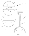
- apparatus comprises an outer shell 10, as seen in Fig. 1, a container 12 normally located in the shell 10, and a handle 14 for pulling the shell 10.
- the outer shell 10 is in this embodiment spherical, but it could also be cylindrical as both shapes have a circular cross section allowing the shell to roll about a diametrical axis.
- the shell 10 has an upper section 16 and a lower section 18, and the axis about which the shell can roll is defined by external stub axles 20 fixed on the lower section 18.
- the sections 16 and 18 are substantially hemispherical though the lower section 18 is slightly larger as it mounts the diametrical stub axles 20.
- a pair of fixed internal stub axles 21 is provided on the inner surface of the lower shell portion 18, as seen in Fig.2, in the same plane as the outer axles 20. In this embodiment the outer and inner axles are coaxial but this need not be so.
- the upper section 16 of the shell has diametrically disposed resilient lugs 22 in each of which are provided a pair of vertically spaced holes 24 and 26 which are in this embodiment conjoined.
- the resilient nature of the lugs 22 allows them to be moved outwardly to disengage holes from the axles 20 or to spring inwardly to engage holes.
- the handle 14 has a handle portion 30 which in this embodiment is telescopic, and a U shaped yoke 32 whose legs 34 and 36 are resiliently biassed inwardly. At the ends of the legs 34 and 36 are holes (not illustrated) which fit over the axles 20, normally inside the lugs 22, so that the shell can be pulled along.
- the container 12 is roughly hemispherical in shape but has a flat bottom 40 and a handle 42.
- Diametrically opposed slots 44 are formed in the sides of the container 12 to engage the inner axles 21 and support the container in the lower portion 18 of the outer shell.
- the clots 44 are keyhole shaped and have an arcuate bearing surface 46 for engaging the inner axle and inclined side surfaces for guiding the axle to the bearing surface 46.
- Fig. 9 shows the container 12 being placed into the lower shell portion 18 with the upper shell section 16 in the open shell position beneath the lower shell section 18.
- the container 12 is freely rotatable on the fixed axles 21 so that as the shell is being pulled along the container remains upright as its centre of gravity is below the axis about which it is suspended.
- An insert 60 is removably located in the container 12 to subdivide it into a number of open topped compartments including, for example, a central one for a bottle.
- the embodiment described is basically intended for use by schoolchildren and is light enough to be pulled and lifted by them.
- the apparatus may be loaded in the morning with the child's lunch and taken to school by the child with the shell in its closed position. At lunchtime, the child can open the shell,. remove the container stand it on its flat bottom on a table, eat lunch, restore the container to the shell and close the shell.
Landscapes
- Engineering & Computer Science (AREA)
- Chemical & Material Sciences (AREA)
- Combustion & Propulsion (AREA)
- Transportation (AREA)
- Mechanical Engineering (AREA)
- Details Of Rigid Or Semi-Rigid Containers (AREA)
Abstract
Description
- This invention is concerned with transport apparatus, and in particular with such apparatus that is sufficiently light to be used by children not only to transport materials for school, for example, but also as playthings.
- The present invention is transport apparatus comprising an outer shell having a circular cross section, a pair of diametrically opposed stub axles fixed on the outer of the shell, a pair of aligned stub axles fixed on the inner surface of the shell, a handle freely rotatable on the external stub axles, and a container freely rotatable on the inner stub axles, the outer shell having an upper section which is removable to allow access to the inner container.
- The outer shell is preferably spherical.
- The outer shell may comprise upper and lower substantially hemispherical sections, the axles being mounted on the lower section while the upper section has diametrically opposed resilient lugs each provided with a hole for removably engaging an external axle.
- Each lug. may have two holes, one for engaging an axle to close the shell and the other engaging the axle to allow rotational movement or the upper shell section relative to the lower section and thus access to the interior of the shell.
- The container may have diametrically opposed brackets for engaging the inner axles to support the container.
- The brackets are preferably keyhole shaped to provide an upper arcuate bearing surface and lower side surfaces for guiding an axle towards the bearing surface.
- The container may have a handle and a flat bottom, and may be subdivided to provide open topped compartments.
- The handle may have a U-shaped yoke whose legs are resiliently biassed into engagement with the outer stub axles.
- Preferably the legs have circular apertures for engaging the stub axles.
- An embodiment of the present invention will now be described by way of example, with reference to the accompanying drawings, in which:-
- Fig. 1
- is a side elevation of an outer shell of an embodiment of apparatus according to the present invention showing the two sections of the shell;
- Fig. 2
- is a side elevation of the lower section of the shell of Fig. 1
- Fig. 3
- is a plan view of a handle used in the embodiment of Fig. 1;
- Fig. 4
- is a side elevation of a container used in the embodiment of Fig. 1;
- Fig. 5
- is a plan view of the container of Fig.4;
- Fig 6
- is a side elevation of the container of Fig.4;
- Figs. 7 and 8
- are respectively a side elevation and a plan view of an insert used with the container of Fig. 4; and
- Fig. 9
- is a side elevation of the container being placed in the outer shell.
- Referring now to figs. 1 to 4, apparatus according to the present invention comprises an
outer shell 10, as seen in Fig. 1, acontainer 12 normally located in theshell 10, and ahandle 14 for pulling theshell 10. - The
outer shell 10, as seen in Figs. 1 and 2, is in this embodiment spherical, but it could also be cylindrical as both shapes have a circular cross section allowing the shell to roll about a diametrical axis. Theshell 10 has anupper section 16 and alower section 18, and the axis about which the shell can roll is defined byexternal stub axles 20 fixed on thelower section 18. Thesections lower section 18 is slightly larger as it mounts thediametrical stub axles 20. A pair of fixedinternal stub axles 21 is provided on the inner surface of thelower shell portion 18, as seen in Fig.2, in the same plane as theouter axles 20. In this embodiment the outer and inner axles are coaxial but this need not be so. - The
upper section 16 of the shell has diametrically disposedresilient lugs 22 in each of which are provided a pair of vertically spacedholes upper holes 26 engage theaxles 20 the two shell sections are secured together in a closed configuration and the shell can roll along the ground, but when thelower holes 24 are engaged with theaxles 20 theupper section 16 can be rotated round thelower section 18 to the position shown in Fig. 9 allowing complete access to the interior of the shell. The resilient nature of thelugs 22 allows them to be moved outwardly to disengage holes from theaxles 20 or to spring inwardly to engage holes. - The
handle 14 has ahandle portion 30 which in this embodiment is telescopic, and a U shaped yoke 32 whoselegs legs axles 20, normally inside thelugs 22, so that the shell can be pulled along. - The
container 12 is roughly hemispherical in shape but has aflat bottom 40 and ahandle 42. Diametrically opposed slots 44, each substantially in the shape of an inverted U, are formed in the sides of thecontainer 12 to engage theinner axles 21 and support the container in thelower portion 18 of the outer shell. In this embodiment the clots 44 are keyhole shaped and have an arcuate bearingsurface 46 for engaging the inner axle and inclined side surfaces for guiding the axle to thebearing surface 46. Fig. 9 shows thecontainer 12 being placed into thelower shell portion 18 with theupper shell section 16 in the open shell position beneath thelower shell section 18. Thecontainer 12 is freely rotatable on thefixed axles 21 so that as the shell is being pulled along the container remains upright as its centre of gravity is below the axis about which it is suspended. - An
insert 60, seen best in Figs. 6 to 8, is removably located in thecontainer 12 to subdivide it into a number of open topped compartments including, for example, a central one for a bottle. - The embodiment described is basically intended for use by schoolchildren and is light enough to be pulled and lifted by them. Typically, the apparatus may be loaded in the morning with the child's lunch and taken to school by the child with the shell in its closed position. At lunchtime, the child can open the shell,. remove the container stand it on its flat bottom on a table, eat lunch, restore the container to the shell and close the shell.
Claims (9)
- Transport apparatus comprising an outer shell having a circular cross section, a pair of diametrically opposed stub axles fixed on the outer of the shell, a pair of aligned stub axles fixed on the inner surface of the shell, a handle freely rotatable on the external stub axles, and a container freely rotatable on the inner stub axles, the outer shell having an upper section which is removable to allow access to the inner container.
- Apparatus as claimed in claim1, in which the outer shell is spherical.
- Apparatus as claimed in claim 2, in which the outer shell comprises upper and lower substantially hemispherical sections, the axles being mounted on the lower section while the upper section has diametrically opposed resilient lugs each provided with a hole for removably engaging an external axle.
- Apparatus as claimed in claim 3, in which each lug has two holes, one for engaging an axle to close the shell and the other engaging the axle to allow rotational movement or the upper shell section relative to the lower section and thus access to the interior of the shell.
- Apparatus as claimed in claim 2, in which the container has diametrically opposed brackets for engaging the inner axles to support the container.
- Apparatus as claimed in claim 5, in which the brackets are preferably keyhole shaped to provide an upper arcuate bearing surface and lower side surfaces for guiding an axle towards the bearing surface.
- Apparatus as claimed in any preceding claim, in which the container has a handle and a flat bottom, and is subdivided to provide open topped compartments.
- Apparatus as claimed in claim 7, in which the handle has a U-shaped yoke whose legs are resiliently biassed into engagement with the outer stub axles.
- Apparatus as claimed in claim 8, in which the legs have circular apertures for engaging the stub axles.
Priority Applications (1)
| Application Number | Priority Date | Filing Date | Title |
|---|---|---|---|
| EP04254627A EP1621099A1 (en) | 2004-07-31 | 2004-07-31 | Transport apparatus |
Applications Claiming Priority (1)
| Application Number | Priority Date | Filing Date | Title |
|---|---|---|---|
| EP04254627A EP1621099A1 (en) | 2004-07-31 | 2004-07-31 | Transport apparatus |
Publications (1)
| Publication Number | Publication Date |
|---|---|
| EP1621099A1 true EP1621099A1 (en) | 2006-02-01 |
Family
ID=34930534
Family Applications (1)
| Application Number | Title | Priority Date | Filing Date |
|---|---|---|---|
| EP04254627A Withdrawn EP1621099A1 (en) | 2004-07-31 | 2004-07-31 | Transport apparatus |
Country Status (1)
| Country | Link |
|---|---|
| EP (1) | EP1621099A1 (en) |
Citations (5)
| Publication number | Priority date | Publication date | Assignee | Title |
|---|---|---|---|---|
| GB539336A (en) * | 1940-03-26 | 1941-09-05 | Walter Gordon Bulteel | Improvements in or relating to carriers for conveying supplies, particularly for use in war |
| US2903219A (en) * | 1955-09-01 | 1959-09-08 | Deering Milliken Res Corp | Tilt truck |
| GB2096547A (en) * | 1981-04-13 | 1982-10-20 | Cranfield Inst Of Tech | Manually operable load-carrying vehicle |
| GB2378158A (en) * | 2001-08-02 | 2003-02-05 | Shaun Alexander Hume | Load transporter with circular cross section |
| GB2398292A (en) * | 2003-01-03 | 2004-08-18 | Shaun Hume | Circular section transport apparatus |
-
2004
- 2004-07-31 EP EP04254627A patent/EP1621099A1/en not_active Withdrawn
Patent Citations (5)
| Publication number | Priority date | Publication date | Assignee | Title |
|---|---|---|---|---|
| GB539336A (en) * | 1940-03-26 | 1941-09-05 | Walter Gordon Bulteel | Improvements in or relating to carriers for conveying supplies, particularly for use in war |
| US2903219A (en) * | 1955-09-01 | 1959-09-08 | Deering Milliken Res Corp | Tilt truck |
| GB2096547A (en) * | 1981-04-13 | 1982-10-20 | Cranfield Inst Of Tech | Manually operable load-carrying vehicle |
| GB2378158A (en) * | 2001-08-02 | 2003-02-05 | Shaun Alexander Hume | Load transporter with circular cross section |
| GB2398292A (en) * | 2003-01-03 | 2004-08-18 | Shaun Hume | Circular section transport apparatus |
Similar Documents
| Publication | Publication Date | Title |
|---|---|---|
| US6386557B1 (en) | Portable cooler caddy and cup holder | |
| US12049344B2 (en) | Container with one or more tray retention portions and support stand | |
| US5071002A (en) | Invertible holder for containers | |
| BE1005911A3 (en) | Educational toy for forms of selection. | |
| US8997995B2 (en) | Beverage transport organizer | |
| US5938023A (en) | Tackle box | |
| US3840204A (en) | Gimbally mounted receptacle | |
| US7431313B1 (en) | Portable tool storage apparatus | |
| KR101995181B1 (en) | Folding hand cart | |
| US8602425B1 (en) | Compact portable safety compliance station and method of making same | |
| US9802522B2 (en) | Vehicle beverage holder | |
| US4659049A (en) | Knock-down outdoor coaster | |
| US9629474B2 (en) | Children's table assembly | |
| US9597992B2 (en) | Vehicle beverage holder | |
| EP1621099A1 (en) | Transport apparatus | |
| US10279830B2 (en) | Dished caster wheel pocket for a platform or dolly | |
| GB2398292A (en) | Circular section transport apparatus | |
| US20150158537A1 (en) | Scooter stand | |
| GB2482142A (en) | Pet food dispenser | |
| US20050082295A1 (en) | Drinking cup including a food storage element | |
| AU2004203607A1 (en) | Transport apparatus | |
| US20180153284A1 (en) | Hammock mounted caddy | |
| US7128299B1 (en) | Beverage container/coaster system | |
| US980852A (en) | Bottle-holding receptacle. | |
| ES2339121T3 (en) | TRAVEL DEVICE OF THE ROTATING PLATE OF A MICROWAVE OVEN WITH REMOVABLE WHEEL SUPPORT. |
Legal Events
| Date | Code | Title | Description |
|---|---|---|---|
| PUAI | Public reference made under article 153(3) epc to a published international application that has entered the european phase |
Free format text: ORIGINAL CODE: 0009012 |
|
| AK | Designated contracting states |
Kind code of ref document: A1 Designated state(s): AT BE BG CH CY CZ DE DK EE ES FI FR GB GR HU IE IT LI LU MC NL PL PT RO SE SI SK TR |
|
| AX | Request for extension of the european patent |
Extension state: AL HR LT LV MK |
|
| 17P | Request for examination filed |
Effective date: 20060731 |
|
| AKX | Designation fees paid |
Designated state(s): AT BE BG CH CY CZ DE DK EE ES FI FR GB GR HU IE IT LI LU MC NL PL PT RO SE SI SK TR |
|
| 17Q | First examination report despatched |
Effective date: 20070307 |
|
| RAP1 | Party data changed (applicant data changed or rights of an application transferred) |
Owner name: FILLABALL HOLDINGS LIMITED |
|
| RIN1 | Information on inventor provided before grant (corrected) |
Inventor name: HUME, SHAUN ALEXANDER |
|
| GRAP | Despatch of communication of intention to grant a patent |
Free format text: ORIGINAL CODE: EPIDOSNIGR1 |
|
| STAA | Information on the status of an ep patent application or granted ep patent |
Free format text: STATUS: THE APPLICATION IS DEEMED TO BE WITHDRAWN |
|
| 18D | Application deemed to be withdrawn |
Effective date: 20090121 |