EP1620953B1 - Bi-stable hinge and mobile station using the same - Google Patents
Bi-stable hinge and mobile station using the same Download PDFInfo
- Publication number
- EP1620953B1 EP1620953B1 EP04750287A EP04750287A EP1620953B1 EP 1620953 B1 EP1620953 B1 EP 1620953B1 EP 04750287 A EP04750287 A EP 04750287A EP 04750287 A EP04750287 A EP 04750287A EP 1620953 B1 EP1620953 B1 EP 1620953B1
- Authority
- EP
- European Patent Office
- Prior art keywords
- stable
- functional component
- foldable
- mobile station
- open position
- Prior art date
- Legal status (The legal status is an assumption and is not a legal conclusion. Google has not performed a legal analysis and makes no representation as to the accuracy of the status listed.)
- Expired - Lifetime
Links
- 239000000463 material Substances 0.000 claims description 33
- 238000004891 communication Methods 0.000 claims description 31
- 230000001681 protective effect Effects 0.000 claims description 19
- 239000000758 substrate Substances 0.000 claims description 15
- 238000004519 manufacturing process Methods 0.000 claims description 8
- 229910052751 metal Inorganic materials 0.000 claims description 6
- 239000002184 metal Substances 0.000 claims description 6
- 238000005452 bending Methods 0.000 claims description 5
- 230000007935 neutral effect Effects 0.000 claims description 5
- 229920000642 polymer Polymers 0.000 claims description 5
- 230000008878 coupling Effects 0.000 claims description 4
- 238000010168 coupling process Methods 0.000 claims description 4
- 238000005859 coupling reaction Methods 0.000 claims description 4
- 230000002441 reversible effect Effects 0.000 claims description 3
- 238000013461 design Methods 0.000 abstract description 19
- 239000002131 composite material Substances 0.000 description 10
- -1 polyethylene Polymers 0.000 description 8
- 239000000835 fiber Substances 0.000 description 6
- 239000004033 plastic Substances 0.000 description 6
- 229920003023 plastic Polymers 0.000 description 6
- 229920005989 resin Polymers 0.000 description 5
- 239000011347 resin Substances 0.000 description 5
- 239000004698 Polyethylene Substances 0.000 description 4
- 239000004743 Polypropylene Substances 0.000 description 4
- 230000008901 benefit Effects 0.000 description 4
- 229920000573 polyethylene Polymers 0.000 description 4
- 229920001155 polypropylene Polymers 0.000 description 4
- OKTJSMMVPCPJKN-UHFFFAOYSA-N Carbon Chemical compound [C] OKTJSMMVPCPJKN-UHFFFAOYSA-N 0.000 description 3
- 230000000712 assembly Effects 0.000 description 3
- 238000000429 assembly Methods 0.000 description 3
- 230000005540 biological transmission Effects 0.000 description 3
- 229920001971 elastomer Polymers 0.000 description 3
- 239000011521 glass Substances 0.000 description 3
- 239000011159 matrix material Substances 0.000 description 3
- 238000000034 method Methods 0.000 description 3
- 238000012986 modification Methods 0.000 description 3
- 230000004048 modification Effects 0.000 description 3
- 239000004814 polyurethane Substances 0.000 description 3
- 229920002635 polyurethane Polymers 0.000 description 3
- 239000005060 rubber Substances 0.000 description 3
- 239000004952 Polyamide Substances 0.000 description 2
- 229910000639 Spring steel Inorganic materials 0.000 description 2
- 230000009471 action Effects 0.000 description 2
- 239000004760 aramid Substances 0.000 description 2
- 229920003235 aromatic polyamide Polymers 0.000 description 2
- 229910052799 carbon Inorganic materials 0.000 description 2
- 230000000694 effects Effects 0.000 description 2
- 238000005516 engineering process Methods 0.000 description 2
- 239000000945 filler Substances 0.000 description 2
- 239000004973 liquid crystal related substance Substances 0.000 description 2
- 230000007246 mechanism Effects 0.000 description 2
- 229920002647 polyamide Polymers 0.000 description 2
- 229920001690 polydopamine Polymers 0.000 description 2
- 229920001296 polysiloxane Polymers 0.000 description 2
- 238000003860 storage Methods 0.000 description 2
- 229920001169 thermoplastic Polymers 0.000 description 2
- 229920002725 thermoplastic elastomer Polymers 0.000 description 2
- 239000004416 thermosoftening plastic Substances 0.000 description 2
- 239000004677 Nylon Substances 0.000 description 1
- 229910000831 Steel Inorganic materials 0.000 description 1
- 229920000122 acrylonitrile butadiene styrene Polymers 0.000 description 1
- 239000004676 acrylonitrile butadiene styrene Substances 0.000 description 1
- 239000000853 adhesive Substances 0.000 description 1
- 230000001070 adhesive effect Effects 0.000 description 1
- DMFGNRRURHSENX-UHFFFAOYSA-N beryllium copper Chemical compound [Be].[Cu] DMFGNRRURHSENX-UHFFFAOYSA-N 0.000 description 1
- 230000000295 complement effect Effects 0.000 description 1
- 239000004020 conductor Substances 0.000 description 1
- 239000002537 cosmetic Substances 0.000 description 1
- 238000011161 development Methods 0.000 description 1
- 230000005611 electricity Effects 0.000 description 1
- 230000007613 environmental effect Effects 0.000 description 1
- 239000003733 fiber-reinforced composite Substances 0.000 description 1
- 239000006260 foam Substances 0.000 description 1
- 229910002804 graphite Inorganic materials 0.000 description 1
- 239000010439 graphite Substances 0.000 description 1
- 230000001939 inductive effect Effects 0.000 description 1
- 239000012528 membrane Substances 0.000 description 1
- 150000002739 metals Chemical class 0.000 description 1
- 229910021652 non-ferrous alloy Inorganic materials 0.000 description 1
- 229920001778 nylon Polymers 0.000 description 1
- 230000003287 optical effect Effects 0.000 description 1
- 239000002861 polymer material Substances 0.000 description 1
- 229920000128 polypyrrole Polymers 0.000 description 1
- 238000005381 potential energy Methods 0.000 description 1
- 230000008569 process Effects 0.000 description 1
- 230000002787 reinforcement Effects 0.000 description 1
- 239000007787 solid Substances 0.000 description 1
- 230000003068 static effect Effects 0.000 description 1
- 239000010959 steel Substances 0.000 description 1
- 238000005728 strengthening Methods 0.000 description 1
- 239000000126 substance Substances 0.000 description 1
- 229920002803 thermoplastic polyurethane Polymers 0.000 description 1
- 229920005992 thermoplastic resin Polymers 0.000 description 1
- 229920001187 thermosetting polymer Polymers 0.000 description 1
- 230000007704 transition Effects 0.000 description 1
- 239000012780 transparent material Substances 0.000 description 1
- 230000000007 visual effect Effects 0.000 description 1
- 238000004804 winding Methods 0.000 description 1
- 210000000707 wrist Anatomy 0.000 description 1
Images



Classifications
-
- H—ELECTRICITY
- H04—ELECTRIC COMMUNICATION TECHNIQUE
- H04B—TRANSMISSION
- H04B1/00—Details of transmission systems, not covered by a single one of groups H04B3/00 - H04B13/00; Details of transmission systems not characterised by the medium used for transmission
- H04B1/38—Transceivers, i.e. devices in which transmitter and receiver form a structural unit and in which at least one part is used for functions of transmitting and receiving
-
- B—PERFORMING OPERATIONS; TRANSPORTING
- B32—LAYERED PRODUCTS
- B32B—LAYERED PRODUCTS, i.e. PRODUCTS BUILT-UP OF STRATA OF FLAT OR NON-FLAT, e.g. CELLULAR OR HONEYCOMB, FORM
- B32B15/00—Layered products comprising a layer of metal
- B32B15/04—Layered products comprising a layer of metal comprising metal as the main or only constituent of a layer, which is next to another layer of the same or of a different material
- B32B15/08—Layered products comprising a layer of metal comprising metal as the main or only constituent of a layer, which is next to another layer of the same or of a different material of synthetic resin
-
- B—PERFORMING OPERATIONS; TRANSPORTING
- B32—LAYERED PRODUCTS
- B32B—LAYERED PRODUCTS, i.e. PRODUCTS BUILT-UP OF STRATA OF FLAT OR NON-FLAT, e.g. CELLULAR OR HONEYCOMB, FORM
- B32B27/00—Layered products comprising a layer of synthetic resin
- B32B27/06—Layered products comprising a layer of synthetic resin as the main or only constituent of a layer, which is next to another layer of the same or of a different material
-
- B—PERFORMING OPERATIONS; TRANSPORTING
- B32—LAYERED PRODUCTS
- B32B—LAYERED PRODUCTS, i.e. PRODUCTS BUILT-UP OF STRATA OF FLAT OR NON-FLAT, e.g. CELLULAR OR HONEYCOMB, FORM
- B32B3/00—Layered products comprising a layer with external or internal discontinuities or unevennesses, or a layer of non-planar shape; Layered products comprising a layer having particular features of form
-
- B—PERFORMING OPERATIONS; TRANSPORTING
- B32—LAYERED PRODUCTS
- B32B—LAYERED PRODUCTS, i.e. PRODUCTS BUILT-UP OF STRATA OF FLAT OR NON-FLAT, e.g. CELLULAR OR HONEYCOMB, FORM
- B32B3/00—Layered products comprising a layer with external or internal discontinuities or unevennesses, or a layer of non-planar shape; Layered products comprising a layer having particular features of form
- B32B3/02—Layered products comprising a layer with external or internal discontinuities or unevennesses, or a layer of non-planar shape; Layered products comprising a layer having particular features of form characterised by features of form at particular places, e.g. in edge regions
- B32B3/04—Layered products comprising a layer with external or internal discontinuities or unevennesses, or a layer of non-planar shape; Layered products comprising a layer having particular features of form characterised by features of form at particular places, e.g. in edge regions characterised by at least one layer folded at the edge, e.g. over another layer ; characterised by at least one layer enveloping or enclosing a material
-
- B—PERFORMING OPERATIONS; TRANSPORTING
- B32—LAYERED PRODUCTS
- B32B—LAYERED PRODUCTS, i.e. PRODUCTS BUILT-UP OF STRATA OF FLAT OR NON-FLAT, e.g. CELLULAR OR HONEYCOMB, FORM
- B32B7/00—Layered products characterised by the relation between layers; Layered products characterised by the relative orientation of features between layers, or by the relative values of a measurable parameter between layers, i.e. products comprising layers having different physical, chemical or physicochemical properties; Layered products characterised by the interconnection of layers
- B32B7/02—Physical, chemical or physicochemical properties
- B32B7/022—Mechanical properties
-
- H—ELECTRICITY
- H04—ELECTRIC COMMUNICATION TECHNIQUE
- H04M—TELEPHONIC COMMUNICATION
- H04M1/00—Substation equipment, e.g. for use by subscribers
- H04M1/02—Constructional features of telephone sets
- H04M1/0202—Portable telephone sets, e.g. cordless phones, mobile phones or bar type handsets
- H04M1/0206—Portable telephones comprising a plurality of mechanically joined movable body parts, e.g. hinged housings
- H04M1/0208—Portable telephones comprising a plurality of mechanically joined movable body parts, e.g. hinged housings characterized by the relative motions of the body parts
- H04M1/0214—Foldable telephones, i.e. with body parts pivoting to an open position around an axis parallel to the plane they define in closed position
- H04M1/0216—Foldable in one direction, i.e. using a one degree of freedom hinge
-
- B—PERFORMING OPERATIONS; TRANSPORTING
- B32—LAYERED PRODUCTS
- B32B—LAYERED PRODUCTS, i.e. PRODUCTS BUILT-UP OF STRATA OF FLAT OR NON-FLAT, e.g. CELLULAR OR HONEYCOMB, FORM
- B32B2307/00—Properties of the layers or laminate
- B32B2307/50—Properties of the layers or laminate having particular mechanical properties
- B32B2307/51—Elastic
-
- B—PERFORMING OPERATIONS; TRANSPORTING
- B32—LAYERED PRODUCTS
- B32B—LAYERED PRODUCTS, i.e. PRODUCTS BUILT-UP OF STRATA OF FLAT OR NON-FLAT, e.g. CELLULAR OR HONEYCOMB, FORM
- B32B2457/00—Electrical equipment
-
- E—FIXED CONSTRUCTIONS
- E05—LOCKS; KEYS; WINDOW OR DOOR FITTINGS; SAFES
- E05D—HINGES OR SUSPENSION DEVICES FOR DOORS, WINDOWS OR WINGS
- E05D1/00—Pinless hinges; Substitutes for hinges
- E05D1/02—Pinless hinges; Substitutes for hinges made of one piece
-
- E—FIXED CONSTRUCTIONS
- E05—LOCKS; KEYS; WINDOW OR DOOR FITTINGS; SAFES
- E05D—HINGES OR SUSPENSION DEVICES FOR DOORS, WINDOWS OR WINGS
- E05D1/00—Pinless hinges; Substitutes for hinges
- E05D1/04—Pinless hinges; Substitutes for hinges with guide members shaped as circular arcs
-
- E—FIXED CONSTRUCTIONS
- E05—LOCKS; KEYS; WINDOW OR DOOR FITTINGS; SAFES
- E05D—HINGES OR SUSPENSION DEVICES FOR DOORS, WINDOWS OR WINGS
- E05D11/00—Additional features or accessories of hinges
- E05D11/0081—Additional features or accessories of hinges for transmitting energy, e.g. electrical cable routing
-
- E—FIXED CONSTRUCTIONS
- E05—LOCKS; KEYS; WINDOW OR DOOR FITTINGS; SAFES
- E05D—HINGES OR SUSPENSION DEVICES FOR DOORS, WINDOWS OR WINGS
- E05D11/00—Additional features or accessories of hinges
- E05D11/10—Devices for preventing movement between relatively-movable hinge parts
- E05D11/1028—Devices for preventing movement between relatively-movable hinge parts for maintaining the hinge in two or more positions, e.g. intermediate or fully open
- E05D11/1078—Devices for preventing movement between relatively-movable hinge parts for maintaining the hinge in two or more positions, e.g. intermediate or fully open the maintaining means acting parallel to the pivot
-
- E—FIXED CONSTRUCTIONS
- E05—LOCKS; KEYS; WINDOW OR DOOR FITTINGS; SAFES
- E05F—DEVICES FOR MOVING WINGS INTO OPEN OR CLOSED POSITION; CHECKS FOR WINGS; WING FITTINGS NOT OTHERWISE PROVIDED FOR, CONCERNED WITH THE FUNCTIONING OF THE WING
- E05F1/00—Closers or openers for wings, not otherwise provided for in this subclass
- E05F1/08—Closers or openers for wings, not otherwise provided for in this subclass spring-actuated, e.g. for horizontally sliding wings
- E05F1/10—Closers or openers for wings, not otherwise provided for in this subclass spring-actuated, e.g. for horizontally sliding wings for swinging wings, e.g. counterbalance
- E05F1/12—Mechanisms in the shape of hinges or pivots, operated by springs
- E05F1/1284—Mechanisms in the shape of hinges or pivots, operated by springs with a leaf or similar spring
-
- E—FIXED CONSTRUCTIONS
- E05—LOCKS; KEYS; WINDOW OR DOOR FITTINGS; SAFES
- E05Y—INDEXING SCHEME ASSOCIATED WITH SUBCLASSES E05D AND E05F, RELATING TO CONSTRUCTION ELEMENTS, ELECTRIC CONTROL, POWER SUPPLY, POWER SIGNAL OR TRANSMISSION, USER INTERFACES, MOUNTING OR COUPLING, DETAILS, ACCESSORIES, AUXILIARY OPERATIONS NOT OTHERWISE PROVIDED FOR, APPLICATION THEREOF
- E05Y2900/00—Application of doors, windows, wings or fittings thereof
- E05Y2900/50—Application of doors, windows, wings or fittings thereof for vehicles
- E05Y2900/53—Type of wing
- E05Y2900/538—Interior lids
-
- E—FIXED CONSTRUCTIONS
- E05—LOCKS; KEYS; WINDOW OR DOOR FITTINGS; SAFES
- E05Y—INDEXING SCHEME ASSOCIATED WITH SUBCLASSES E05D AND E05F, RELATING TO CONSTRUCTION ELEMENTS, ELECTRIC CONTROL, POWER SUPPLY, POWER SIGNAL OR TRANSMISSION, USER INTERFACES, MOUNTING OR COUPLING, DETAILS, ACCESSORIES, AUXILIARY OPERATIONS NOT OTHERWISE PROVIDED FOR, APPLICATION THEREOF
- E05Y2999/00—Subject-matter not otherwise provided for in this subclass
-
- Y—GENERAL TAGGING OF NEW TECHNOLOGICAL DEVELOPMENTS; GENERAL TAGGING OF CROSS-SECTIONAL TECHNOLOGIES SPANNING OVER SEVERAL SECTIONS OF THE IPC; TECHNICAL SUBJECTS COVERED BY FORMER USPC CROSS-REFERENCE ART COLLECTIONS [XRACs] AND DIGESTS
- Y10—TECHNICAL SUBJECTS COVERED BY FORMER USPC
- Y10T—TECHNICAL SUBJECTS COVERED BY FORMER US CLASSIFICATION
- Y10T428/00—Stock material or miscellaneous articles
- Y10T428/24—Structurally defined web or sheet [e.g., overall dimension, etc.]
- Y10T428/24479—Structurally defined web or sheet [e.g., overall dimension, etc.] including variation in thickness
Definitions
- the present invention relates generally to mobile-stations, and more specifically to a mobile station having a folded design encompassing a bi-stable member.
- LCDs liquid crystal displays
- folded mobile station design has developed, in part, to provide greater durability to modem mobile stations. As will become apparent, folded mobile stations also provide increased utility due to their relatively compact size.
- a folded mobile station is one that may be, generally speaking, folded from two parts into one more compact part. More specifically, as illustrated in Figures 1A - 1C , folded mobile stations 100 are generally comprised of a first functional component 101 and a second functional component 102. The first and second functional components 101,102 are mechanically coupled to one another by a hinge assembly 175 such that each may be folded over the other in a clam-shell type action. Accordingly, folded mobile stations 100 possess an "open” and a folded or "closed” position.
- Figure 1A provides one example of a conventional mobile station 100 (a mobile phone) oriented in the open position.
- the first and second functional components 101, 102 of the mobile station 100 include various internal circuitry and operational elements.
- the first functional component 101 is depicted as including a LCD 150.
- the LCD 150 is visible through, and protected by, a clear plastic cover 151.
- a speaker port 154 is comprised of a series of small openings formed in first portion 101, and lies adjacent to an internal speaker (not shown) that is also housed by the first portion 101.
- the first portion 101 also typically includes circuitry for driving the LCD 150 and the internal speaker (not shown).
- the second portion 102 of a conventional mobile station 100 generally includes a microphone port 155 that is adjacent to an internal microphone (not shown).
- a keypad 160 is also provided that is comprised of a series of keys extending through a plurality of openings from an otherwise internally disposed key mat.
- the second portion 102 of mobile station 100 also houses the internal circuitry associated with the above described microphone 155 and keypad 160.
- An antenna for facilitating radio frequency (RF) communications may be located in either the first portion 101 or the second portion 102, or may be distributed between them.
- Mobile station batteries (not shown) are typically stored in the second portion 102, due to the limited space available in the first portion 101 as a result of the LCD 150 and speaker 154 placement.
- An external power supply (not shown), such as an AC adaptor, may be connected through a power port 144.
- external headphones may be connected to the mobile station 100 at the external-device port 145.
- FIG. 1B illustrates a known mobile station 100 in the closed position.
- the first portion 101 and the second portion 102 close in such a manner as to protect the keypad 160 and LCD 150.
- known mobile stations 100 cannot be used in a closed configuration, although such functionality may be achieved by employing an external microphone and speaker (not shown). Such devices are often used in 'hands-free' operation, and are readily connected through an external-device port 145.
- the folded design of modem mobile stations 100 distinguish them from their predecessors by accommodating safe storage on belts, in pockets, purses, or glove compartments without subjecting the sensitive internal components to damage from keys or other objects frequently encountered in such environments.
- folded mobile stations 100 possess features that are both useful and desirable to consumers. In addition to the durability and size improvements discussed above, many users prefer the aesthetics of folding designs over others. Despite the above improvements, the conventional folding mobile station design depicted in Figures 1A and 1B is still not optimal.
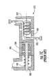
- conventional folding mobile stations 100 use a cylindrical hinge assembly 175 similar to a standard door hinge, to bind the first functional component 101 to the second functional component 102. As illustrated in Figure 1C , this hinge assembly 175 is relatively complex and more importantly, requires highly labor-intensive assembly operations and thus, is costly to manufacture.
- conventional hinge assemblies 175 are comprised of hinge members 176,177 and 181 that extend from the first functional component 101, and hinge members 178 and 179 that extend from the second functional component 102. These hinge members 175-179 and 181 are held together by a hinge pin 180 that extends through openings (not shown) formed in each hinge member. During assembly, the hinge pin 180 must be carefully inserted through the openings provided in the hinge members 175-179 and 181, and also must be threaded through a pre-assembled spring 182, a profile indent part (dynamic) 183, a profile indent part (static) 184 as shown in Figure 1C . These latter components are provided to maintain the mobile station 100 in either an open or closed position as known to one of ordinary skill in the art. Finally, a flexible printed circuit or cable bundle 185 must be awkwardly wrapped around the pin 180 to ensure that the first functional component 101 is electrically connected to the second functional component 102.
- the complexity of the above hinge design results in cost-prohibitive and bulky hinge assemblies.
- the above hinge assembly requires precision elements, high part counts, and relatively long assembly times that all add to the manufactured cost.
- the complex prior art hinge designs hinder the ability of designers to make stylish modifications.
- it would be highly desirable to provide an improved hinge design for a foldable mobile station that is relatively simple to assemble and compliments the overall aesthetic appeal of the mobile station.
- JP 04-277958 discloses a telephone set in which the microphone and speaker are linked to a keypad via foldable portions.
- the telephone set can be locked into a "ring" configuration for security and/or allowing it to be attached to a bag, wrist or belt.
- An object of the present invention is the provision of an improved hinge design for a mobile station, such as a mobile phone or other foldable electronic device, that simplifies hinge assembly and thus, provides a more cost-effective manufactured product.
- the improved hinge design may complement the aesthetic appeal of such a foldable mobile station and result in less applied stress on various internal elements.
- a bi-stable member for a mobile station comprises a first part, a second part and at least one foldable portion, comprised of bi-stable materials, configured to foldably couple said first part to said second part, wherein said at least one foldable portion is further configured to bias said first and second parts between a folded position and an open position and said at least one foldable portion includes a substantially flattened transverse cross-section in said folded position and a substantially C-shaped transverse cross-section in said open position.
- the foldable portion generally includes opposed lateral edges and stiffening portions disposed adjacent thereto.
- a median region is defined between the stiffening portions such that the stiffening portions are configured substantially planar to the median region in the folded position, and substantially non-planar to the median region in the open position.
- the bi-stable member may comprise a laminate structure having a resilient substrate layer comprised of a polymer laminate, a strip of mesh or spring metal, a fiber reinforced composite or some combination thereof, that is biased toward the open position, and a plastically deformable layer configured to oppose the bias of the resilient substrate layer in the folded position. Accordingly, the folded position and the open position are reversible and stable positions.
- a laminate structure may comprise a plurality of pre-stressed elements disposed adjacent the plastically deformable layer, wherein the pre-stressed elements are under tension in the open position and further configured such that the tension is at least partially relieved in the folded position.
- Such pre-stressed elements may be aligned substantially axially within the laminate structure.
- the laminate structure of the bi-stable member comprises a plurality of pre-stressed elements, disposed adjacent the resilient substrate layer, that are under tension in the folded position and further configured such that the tension is at least partially relieved in the open position, which may be arranged substantially transversely within the laminate structure.
- the invention also provides a foldable device comprising a first functional component, a second functional component, a communication member for electrically connecting said first functional component to said second functional component and said bi-stable member for biasing said first and second functional components into an open position and a folded position.
- Mobile stations and other foldable electronic devices include first and second functional components that are pivotally coupled together.
- the first and second functional components are mechanically coupled in foldable relation by a bi-stable member.
- the foldable device may include a protective member disposed between the first functional component and the second functional component for protecting the communication member in the open position. Such a protection member may be arranged to define a maximum operating angle and/or a minimum fold radius. Alternatively, or additionally, the foldable device may include a protective member disposed between the first functional component and the second functional component for protecting the communication member in the folded position, which may, optionally, define one or more of a maximum operating angle and a minimum fold radius.
- the present invention also includes a method of manufacturing a mobile station comprising the steps of providing a bi-stable member for biasing a mobile station between an open position and a folded position, the bi-stable member defining at least one foldable portion having a substantially flattened transverse cross-section in the folded position and a substantially C-shaped or curved transverse cross-section in the open position, coupling a first functional component to the foldable portion of the bi-stable member and coupling a second functional component to the foldable portion of the bi-stable member.
- the method of producing a mobile station may further comprise the step of electrically connecting a communication member between the first functional component and the second functional component.
- the method may include the step of shielding the communication member in the open and closed positions.
- the mobile station of the present invention uses bi-stable structures.
- These bi-stable structures comprise one or more extendable, coilable, members that can be advanced from a coiled or retracted state to an extended state.
- the simplest of the conventional bi-stable structures is the common steel tape measure.
- Suitable structures are disclosed in the following United States Patents issued to Daton-Lovett: United States Patent Number 6,217, 975 granted on April 17,2001 and United States Patent Number 6,256,938 granted on July 10, 2001 .
- Such bi-stable structures are available from Rolatube Teclmology Limited (United Kingdom) and from other suppliers.
- FIG. 2 depicts one example of an extendable, coilable, bi-stable structure 200 in accordance with the known prior art.
- the term "bi-stable” refers to materials or composites that are configurable or biased toward two stable shapes.
- conventional bi-stable structures 200 are comprised of materials that are biased toward an extended shape or state, and additional materials that are biased opposite to the first materials toward a coiled shape or state.
- the bi-stable structure 200 of Figure 2 includes portions that are configured in each of the above-referenced states, i.e., a coiled portion 210 and an extended portion 220.
- a conventional bi-stable structure 200 In its extended state, a conventional bi-stable structure 200 has a curved, semi-circular, or circular transverse cross-section as illustrated in Figure 2A . In its coiled state, a conventional bi-stable structure 200 has a substantially flattened transverse cross-section as illustrated in Figure 2B . Although depicted in Figures 2 and 2A as having a circular cross-section, bi-stable structures 200 can alternatively have oval, curved, C-shaped or other cross-sectional configurations as known in the art. The differences in the transverse cross-sections of the two states allow a bi-stable structure to be coiled up or retracted into a much smaller volume than it could otherwise occupy in its extended state.
- bi-stable structures 200 of the type illustrated in Figure 2 are typically comprised of a resilient substrate layer, such as a spring metal in the case of a tape measure, which is biased toward the extended form (e.g., biased toward causing the member to have a curved cross-section).
- the resilient substrate can be laminated with a plastically deformable (i.e., capable of plastic deformation) layer that tends to bias the member towards the retracted form (e.g., having a flattened cross-section).
- a properly laminated tape measure e.g., including a plastically deformable layer
- a plastically deformable layer could remain in either the extended or coiled forms without conventional latches or winding mechanisms.
- the plastically deformable layer would oppose and possibly negate, the inherent bias of the tape measure that would otherwise return it to its extended form.
- the material properties of the resilient and plastically deformable layers may be selected or altered to enhance the performance of the bi-stable structure 200.
- the modulus of elasticity of the bi-stable structure 200 can be modified across the length, width, and/or thickness of the structure 200 to achieve desired characteristics (e.g., end stop, torsional rigidity, force feedback curves, etc.) as known to one of ordinary skill in the art.
- desired characteristics e.g., end stop, torsional rigidity, force feedback curves, etc.
- Such design customization may be particularly useful for reducing the overall thickness (and weight) of the bi-stable structure 200 and further altering the application force necessary to extend or retract the bi-stable structure 200.
- the materials used to form bi-stable structures may be selected to possess other desired characteristics (e.g., high toughness, high thermal deformation resistance, etc.) as known in the art.
- bi-stable structures have resilient layers comprising one or more polymer composite layers having a thermoplastic matrix (e.g., polyethylene or polypropylene) with various configurations of pre-stressed elements attached to or embedded therein.
- a composite layer of a bi-stable structure may include a thermoplastic layer having a plurality of pre-stressed glass, carbon, aramid or polymeric fibers disposed therein. These fibers can be oriented at different angles relative to one another in the plane of the bi-stable structure such that the structure is biased toward coiled and extended positions.
- one set of fibers may be oriented generally axially and a second set of fibers may be oriented substantially transversely to produce a desired "bi-stable" effect.
- Various embodiments of the present invention will now be described with reference to certain types of bi-stable structures. It should be noted however, that the inventive concepts embodied by the present invention are not limited to the specific bi-stable structures expressly set out in the foregoing specification, and may in fact, incorporate any bi-stable structure that is commonly known in the art.
- FIGS 3A-3C illustrate one application of the above technology to mobile station design in accordance with several embodiments of the present invention.
- the term "mobile station” refers to mobile phones, PDAs, pagers, calculators, laptop computers, or other similar foldable electronic devices as commonly known in the art.
- a mobile station 300 (such as a mobile phone) is comprised of a first functional component 301 that is coupled in foldable relation to a second functional component 302. Accordingly, the mobile station 300 can be configured to achieve a folded position as shown in Figures 3A and 3B , and an open position as shown in Figure 3C .
- the first functional component 301 is coupled to the second functional component 302 via a bi-stable member 310.
- the shape and functionality of the bi-stable member 310 according to several embodiments of the present invention will be described in detail below.
- Figure 3C illustrates an "opened" mobile station 300 in accordance with one embodiment of the present invention.
- the first and second functional components 301, 302 combine to define an operation angle ⁇ .
- this operation angle ⁇ may vary considerably.
- the operation angle ⁇ may be between 150 and 180 degrees, while in other applications (e.g., laptop computers) the preferred operation angle ⁇ may be considerably less.
- the first and second functional components 301, 302 of the mobile station 300 include respective first and second inner surfaces 303, 304.
- a plurality of relatively delicate operational elements e.g., a display 350, a keypad 360, a speaker port 354, a microphone port 355 , etc.
- the plurality of operational elements are protected from potentially damaging impact or contact with foreign substances.
- Figure 3C depicts certain operational elements adjacent either the first or second functional components 301, 302 it is important to note that the present invention is not limited to the depicted configuration, and in fact, the various elements may be disposed adjacent either the first or second functional components 301, 302 as known in the art.
- the first and second functional components 301, 302 are coupled in foldable relation to one another by a bi-stable member 310.
- various embodiments of the present invention use the inherent tendency of bi-stable structures to maintain either a coiled or extended state, as a means to bias a mobile station 300 toward either an open or folded state, respectively.
- the bi-stable member 310 serves to bias the mobile station 300 toward either a folded position (as depicted in Figures 3A and 3B ) or an open position (depicted in Figure 3C ).
- an opening force or a closing force must be applied by a user when respectively opening or closing the mobile station 300, thereby overcoming the inherent tendency of the bi-stable member 310 to remain in either the folded or open position.
- This functionality is particularly desirable to protect against inadvertent opening during periods of non-use, or inadvertent closing during periods of use.
- the bi-stable member 310 also functions to enclose and protect the first and second functional components 301, 302 along with their respective operational elements (e.g., LCD display 350, keypad 360, etc.). In various other embodiments, however, this need not be the case as a bi-stable member could be provided within a more conventional housing or set of housings (not shown); wherein the bi-stable member performs the biasing function and the housing(s) perform the above protective enclosure function.
- Figures 4 and 5 depict a bi-stable member 410 according to various embodiments of the present invention.
- Figure 4 depicts a bi-stable member 410 in an open position
- Figure 5 depicts a bi-stable member 410 in a folded position.
- the bi-stable member 410 comprises first and second parts 411, 412 that are axially spaced from one another by a foldable portion 415.
- the first and second parts 411, 412 are configured to support and be connected to the first and second functional components (as shown in Figures 3A-3C ).
- the bi-stable member 410 When transitioning between open and folded positions the bi-stable member 410 can be folded adjacent a fold-axis F such that the second part 412 is positioned over the first part 411 as shown in Figure 5 .
- the bi-stable member 410 is readily reversible such that the first part 411 may be folded over the second part 412.
- the bi-stable member 410 may be completely comprised of bi-stable materials as referenced above, or alternatively, may be only partially comprised of such materials (e.g., one or more foldable portions) with the remainder being comprised of conventional materials.
- the first and second parts 411, 412 may be comprised of conventional materials while the foldable portion 415 is comprised of bi-stable materials.
- a bi-stable member 410 is not limited to this configuration.
- the fold-axis F may be non-centrally located within the foldable portion 415, thereby producing a first part 411 (or second part 412) that is larger than the opposed second part 412 (or first part 411).
- the foldable portion 415 itself (and thus the fold-axis F) may not be centrally located as shown, thereby producing a similar effect wherein the first and second parts 411, 412 have different sizes.
- multiple foldable portions 415 may be provided, such that a tri-fold (two foldable portions), quad-fold (three foldable portions) or other similar multiple-fold configuration is produced, as known to one of ordinary skill in the art.
- the foldable portion 415 is bounded by opposed lateral edges 418.
- stiffening portions 420 are formed adjacent the lateral edges 418 thereby defining a median region 423 therebetween.
- the stiffening members 420 When configured in the open position, the stiffening members 420 are curved away from the median region 423 producing the substantially non-planar transverse cross-section illustrated in Figure 4A .
- the stiffening members 420 function to stabilize the bi-stable member 410 against folding in unintended directions (e.g., in the direction opposite an intended folding direction) and further provide the curved transverse cross-section that is characteristic of a bi-stable material.
- the transverse cross-section (defined by the stiffening members 420 and median region 423) of the foldable portion 415 may be substantially C-shaped as shown, generally curved, or alternatively may be semi-circular, or possibly circular as known to one of ordinary skill in the art.
- the bi-stable materials that comprise the foldable portion 415 cause the stiffening members 420 to rotate outwardly such that a substantially planar or flattened transverse cross-section (defined between the stiffening members 420 and median region 423) is produced as shown in Figure 5A .
- the stiffening members 420 may be axially bounded by a plurality of notches 407 to isolate the first and second parts 411, 412, thereby reducing the stress and curvature applied to the first and second parts 411, 412, as the bi-stable member 410 transitions between open and folded positions.
- these notches 407 may be optionally omitted such that the curvature of the stiffening members 420 extends axially onto the first and second parts and is configured to protect at least a portion of the first and second functional components (not shown).
- the bi-stable member 510, 610 may be comprised of a variety of bi-stable materials.
- the bi-stable member 510 is comprised of a resilient substrate layer 525 that is biased toward an open position (e.g., curved transverse cross-section) and a plastically deformable layer 527 that is configured to oppose the bias of the resilient substrate layer (e.g., to encourage a substantially flattened transverse cross-section) in the folded position.
- the resilient substrate 525 may be comprised of a pre-stressed polymer material (such as the composite structures described below), a spring steel or other similar resilient metals, or a non-ferrous alloy such as beryllium copper (although the latter material is generally not preferred due to environmental concerns).
- the resilient substrate 525 may include one or more layers of spring steel having a thickness approximating 0.05 - 0.5 mm that are spaced apart by a soft resin layer.
- the resilient substrate 525 (or a portion thereof) may be comprised of electrically sensitive materials such as polypyrrole materials.
- the resilient layer 525 may be biased toward either the open or folded positions by the application of an electric current or field as known to one of ordinary skill in the art.
- the plastically deformable layer 527 may be comprised of any polymer or other material that is capable of plastic deformation at ambient temperatures. Suitable materials may include polypropylene, polyethylene, polyamides (e.g., nylon), polyurethane, thermo plastic elastomers or other similar materials. Alternatively, in other embodiments, a thermo setting material such as rubber or silicone may be used.
- the plastically deformable layer 527 undergoes plastic deformation such that it becomes biased in favor of the folded position. Accordingly, in the folded position the plastically deformable layer 527 opposes, or even negates, the potential energy that has been stored in the resilient substrate 525 during folding. This causes the bi-stable member 510 to have a relatively stable folded position.
- additional latches, locks or other guiding surfaces may be provided to further stabilize the folded position.
- strengthening ribs, supports, or locking mechanisms may be provided to stabilize a desired open position as known in the art.
- the bi-stable member 610 may be comprised of at least one composite layer 625 comprising a thermoplastic resin 628, such as polypropylene, polyethylene, polyamide, polyurethane, etc., and a plurality of pre-stressed elements 629, 629' formed within or laminated adjacent the resin 628.
- the resin (or matrix) 628 suspends the pre-stressed elements 629, 629' in a given position relative to one another.
- the pre-stressed elements 629, 629' may include fibers of pre-stressed glass, carbon, aramid, graphite, rubber, metal or other similar materials as known in the art.
- the pre-stressed elements 629, 629' are configured to produce an elastic resilient layer having specific material properties across various axes.
- the composite layer 625 may include a plurality of axially-aligned pre-stressed elements 629 that are configured under tension when the bi-stable member 610 is in the open position, and further configured such that the tension is at least partially relieved when the bi-stable member 610 is in the folded position.
- the composite layer 625 may include a plurality of transversely-aligned pre-stressed elements 629' that are under tension in the folded position, and further configured such that the tension is at least partially relieved in the open position. Further, it is not necessary that such fibers be oriented at 90 degree angles from one another.
- the substantially axial pre-stressed elements 629 and the substantially transverse pre-stressed elements 629' may be provided in a single composite layer 625 as shown, or alternatively, may be provided in multiple composite layers (not shown) as known in the art. In multiple layer applications, the resin or matrix of adj acent layers may have differing elastic stiffnesses to achieve specific material properties as known in the art.
- plastically deformable layers 627 may be laminated to the one or more composite layers 625 to oppose or negate the respective biases of the pre-stressed elements 629, 629' provided therein.
- the plastically deformable layers 627 may be omitted by merely selecting a resin 628 or filler material that is capable of plastic deformation at ambient temperatures as known in the art.
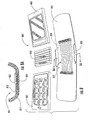
- Figure 7 provides an exploded view of a mobile station 700 in accordance with one embodiment of the present invention.
- the mobile station 700 includes a bi-stable member 710 for supporting a first functional component 701 and a second functional component 702.
- the first and second functional components 701, 702 may be coupled to the bi-stable member 710 via various fasteners as known in the art.
- screws 709 may be set into the first and second functional components 701, 702 through holes 716 provided in the bi-stable member 710 as shown.
- other fasteners such as adhesives, rivets, clips, studs, (not shown) and the like may be used.
- the first functional component 701 is electrically connected to the second functional component 702 by a communication member 730.
- the communication member 730 electrically connects the first functional component 701 and the second functional component 702.
- the communication member 730 may be comprised of a flexible electrical connector (as shown) as commonly known in the art. In other embodiments, however, the communication member 730 may take on other specific tasks, such as providing a receiving or transmitting antenna or facilitating various internal electronic circuitry.
- the communication member 730 may comprise conductive leads printed on a Flexible Printed Circuit (FPC), or alternatively, may include conductors or other devices for optical transmission, inductive near field transmission or short range transmissions such as Bluetooth, RFID, 802.11 and the like.
- FPC Flexible Printed Circuit
- a protective member 740 is provided to shield the communication member 730 against cuts, wear, hits, sharp bends etc.
- the protective member 740 may comprise a variety of shapes and may be composed of a variety of materials.
- the protective member 740 is comprised of a rigid polymer (e.g., polypropylene, polyurethane, polyethylene, ABS, etc.) that is divided into a plurality of inter-connected wedge-shaped segments 741 such that the mobile station 700 is forced to maintain a fold radius R (as shown in Figure 3B ) that will not damage the communication member 740.
- the protective member 740 is designed to maintain a fold radius R of between 8-10 mm.
- the electrical cable bundle 185 is tightly wound about a narrow pin 180 and threaded into a narrow channel (on the order of 6mm). Accordingly, prior art electrical cable bundles 185 are prone to stress, wear and potential breaking.
- the protective member 740 may be comprised of an air filled molded membrane (not shown) that is made from silicone, rubber, a thermoplastic elastomer, a thermoplastic urethane or some combination thereof. In other embodiments, the protective member 740 may be comprised of an open celled foam (not shown) made from a plastic or other similar materials. As is apparent to one of ordinary skill in the art, the precise configuration of the protective member 740 may vary from application to application depending on the selected materials and available space.
- the present invention results in a number of benefits.
- the present invention significantly limits manufacturing costs by enabling z-axis assembly, wherein the x-y plane is defmed along the plane of the bi-stable member as shown in Figure 7 .
- the components that combine to form a mobile station 700 e.g., a bi-stable member 710, a communication member 730, a protective member 740, first and second functional components 701, 702, etc.
- a mobile station 700 e.g., a bi-stable member 710, a communication member 730, a protective member 740, first and second functional components 701, 702, etc.
- This relatively simply process stands in sharp contrast to the intricate aligning, threading, and cable bundle wrapping operations required to produce hinge assemblies according to the known prior art.
- the embodiments are illustrative of the mechanical and electrical interconnection of the parts of the electronic devices. Details of the electronic features of the electronic devices are not needed for one skilled in the art to understand the invention as described and shown. For example, there may be an interface 708 used to connect power and interface cables, a keypad 760 or other such user interface, or a display 750 for the presentation of information.
- the protective member may be omitted entirely as the communication member 830 (e.g., a flexible printed circuit) is disposed within or integral to the foldable portion 815 of the bi-stable member 810. Accordingly, the bi-stable member 810 at least partially encloses the communication member 830 and thereby protects the member 830 from contact with objects that might cause damage.
- the communication member 830 is disposed adj acent a "neutral bending line" that is inherent within bendable members (e.g., the foldable portion 815 of the bi-stable member 810) as known in the art.
- the foldable portion 815 of the bi-stable member 810 includes a first surface 813 and a second surface 814.
- the "neutral bending line" 812 is a theoretical axis or plane defined within the foldable portion 815 between the first and second surfaces 813, 814 as referenced above and known in the art.
- the neutral bending line represents that portion of the bendable material that is not stretched or compressed as the bi-stable member 810 is folded. Accordingly, by placing the communication member 830 substantially adjacent the neutral bending line 812 of the foldable portion 815 of the bi-stable member 810 as shown, stretching or compressing of the communication member 830 may be reduced.
Landscapes
- Engineering & Computer Science (AREA)
- Mechanical Engineering (AREA)
- Signal Processing (AREA)
- Computer Networks & Wireless Communication (AREA)
- Telephone Set Structure (AREA)
- Casings For Electric Apparatus (AREA)
- Hinge Accessories (AREA)
- Aerials With Secondary Devices (AREA)
- Hinges (AREA)
- Vehicle Body Suspensions (AREA)
- Polyamides (AREA)
- Adhesives Or Adhesive Processes (AREA)
- Piezo-Electric Or Mechanical Vibrators, Or Delay Or Filter Circuits (AREA)
Abstract
Description
- The present invention relates generally to mobile-stations, and more specifically to a mobile station having a folded design encompassing a bi-stable member.
- The manufacture and design of today's mobile stations (also known as mobile phones, PDAs, pagers, laptop computers and the like) is constantly evolving. Early mobile station designs were necessarily large and bulky. The radio communications equipment and battery units necessary for their operation generally were carried in one oversized unit; although in at least one early and cumbersome design the unit was actually divided into two pieces which were then connected by a power cable. Advances in integrated circuitry and electricity storage technology have enabled mobile station designers to create smaller and smaller devices. These instruments are not only lighter, but also less cumbersome and easier to transport. For example, mobile stations are no longer required to be permanently installed in automobiles or connected to bulky separately-carried battery packs. Essentially, today's smaller, more useful mobile stations have simply become more fashionable.
- Unfortunately, several drawbacks have followed this new fashionability and convenience. For example, the increased mobility of today's mobile stations has the unintended drawback of subjecting these mobile stations to an ever-increasing number of potentially damaging environments. For modem day consumers, these environments include pockets, briefcases, purses, gym bags, glove compartments and toolboxes where the mobile station can contact harmful solid objects and moisture that may cause structural and/or cosmetic damage to the relatively delicate internal and operational elements (e.g., LCD displays, microphone and speaker ports, keypads, etc.) of the mobile station. Accordingly, mobile stations are highly susceptible to damage. To make matters worse, market forces continue to drive mobile stations smaller, therefore, making it more difficult to add bulky structural reinforcements that might protect the mobile stations.
- This risk of damage is exacerbated by the number of externally accessible components that are provided on modem mobile stations. One of the most prominent of these components is the visual display. Initially, such displays were limited to small, light emitting diodes (LEDs) that indicated whether the mobile station was "on" or, regarding mobile phones, whether a call was in progress. Gradually, more advanced LED displays were developed that were capable of displaying a dialed telephone number, the current time, or other simple information. More recently, liquid crystal displays (LCDs) have become commonplace. An LCD is made by sandwiching an electrically sensitive liquid-crystal material between two very thin pieces of glass or other transparent materials. They are, therefore, easily susceptible to damage by even a relatively minor impact. Despite the hard, transparent cover or similar protective device, generally added to limit this vulnerability, LCDs remain one of the most easily damaged components in modem mobile stations.
- The folded mobile station design has developed, in part, to provide greater durability to modem mobile stations. As will become apparent, folded mobile stations also provide increased utility due to their relatively compact size. A folded mobile station is one that may be, generally speaking, folded from two parts into one more compact part. More specifically, as illustrated in
Figures 1A - 1C , foldedmobile stations 100 are generally comprised of a firstfunctional component 101 and a secondfunctional component 102. The first and second functional components 101,102 are mechanically coupled to one another by ahinge assembly 175 such that each may be folded over the other in a clam-shell type action. Accordingly, foldedmobile stations 100 possess an "open" and a folded or "closed" position. -
Figure 1A provides one example of a conventional mobile station 100 (a mobile phone) oriented in the open position. As known to one of ordinary skill in the art, the first and secondfunctional components mobile station 100 include various internal circuitry and operational elements. For example, the firstfunctional component 101 is depicted as including aLCD 150. TheLCD 150 is visible through, and protected by, a clearplastic cover 151. Aspeaker port 154 is comprised of a series of small openings formed infirst portion 101, and lies adjacent to an internal speaker (not shown) that is also housed by thefirst portion 101. Further, thefirst portion 101 also typically includes circuitry for driving theLCD 150 and the internal speaker (not shown). - The
second portion 102 of a conventionalmobile station 100 generally includes amicrophone port 155 that is adjacent to an internal microphone (not shown). Akeypad 160 is also provided that is comprised of a series of keys extending through a plurality of openings from an otherwise internally disposed key mat. As with thefirst portion 101, thesecond portion 102 ofmobile station 100 also houses the internal circuitry associated with the above describedmicrophone 155 andkeypad 160. An antenna for facilitating radio frequency (RF) communications (not shown) may be located in either thefirst portion 101 or thesecond portion 102, or may be distributed between them. Mobile station batteries (not shown) are typically stored in thesecond portion 102, due to the limited space available in thefirst portion 101 as a result of theLCD 150 andspeaker 154 placement. An external power supply (not shown), such as an AC adaptor, may be connected through apower port 144. Similarly, external headphones (not shown) may be connected to themobile station 100 at the external-device port 145. - When the mobile station is thus "opened," the user has access to the
keypad 160 and can conveniently place thespeaker port 154 andmicrophone port 155 in a position for voice communication. Themobile station 100 may also be "closed" by folding thefirst portion 101 to meet thesecond portion 102 in a clam-shell action as indicated by the arrow.Figure 1B illustrates a knownmobile station 100 in the closed position. Advantageously, thefirst portion 101 and thesecond portion 102 close in such a manner as to protect thekeypad 160 andLCD 150. Generally speaking, knownmobile stations 100 cannot be used in a closed configuration, although such functionality may be achieved by employing an external microphone and speaker (not shown). Such devices are often used in 'hands-free' operation, and are readily connected through an external-device port 145. As alluded to above, the folded design of modemmobile stations 100 distinguish them from their predecessors by accommodating safe storage on belts, in pockets, purses, or glove compartments without subjecting the sensitive internal components to damage from keys or other objects frequently encountered in such environments. - As should by now be apparent, folded
mobile stations 100 possess features that are both useful and desirable to consumers. In addition to the durability and size improvements discussed above, many users prefer the aesthetics of folding designs over others. Despite the above improvements, the conventional folding mobile station design depicted inFigures 1A and 1B is still not optimal. For example, conventional foldingmobile stations 100 use acylindrical hinge assembly 175 similar to a standard door hinge, to bind the firstfunctional component 101 to the secondfunctional component 102. As illustrated inFigure 1C , thishinge assembly 175 is relatively complex and more importantly, requires highly labor-intensive assembly operations and thus, is costly to manufacture. - In particular,
conventional hinge assemblies 175 are comprised of hinge members 176,177 and 181 that extend from the firstfunctional component 101, and hingemembers functional component 102. These hinge members 175-179 and 181 are held together by ahinge pin 180 that extends through openings (not shown) formed in each hinge member. During assembly, thehinge pin 180 must be carefully inserted through the openings provided in the hinge members 175-179 and 181, and also must be threaded through apre-assembled spring 182, a profile indent part (dynamic) 183, a profile indent part (static) 184 as shown inFigure 1C . These latter components are provided to maintain themobile station 100 in either an open or closed position as known to one of ordinary skill in the art. Finally, a flexible printed circuit orcable bundle 185 must be awkwardly wrapped around thepin 180 to ensure that the firstfunctional component 101 is electrically connected to the secondfunctional component 102. - As will be apparent to one of ordinary skill in the art, the complexity of the above hinge design results in cost-prohibitive and bulky hinge assemblies. For example, the above hinge assembly requires precision elements, high part counts, and relatively long assembly times that all add to the manufactured cost. In addition, the complex prior art hinge designs hinder the ability of designers to make stylish modifications. In light of the foregoing, it would be highly desirable to provide an improved hinge design for a foldable mobile station that is relatively simple to assemble and compliments the overall aesthetic appeal of the mobile station. Furthermore, it would be desirable to provide a hinge design that maintains the durability and size benefits realized by the development of modern foldable mobile stations.
-
JP 04-277958 - An object of the present invention is the provision of an improved hinge design for a mobile station, such as a mobile phone or other foldable electronic device, that simplifies hinge assembly and thus, provides a more cost-effective manufactured product.
- Moreover, the improved hinge design may complement the aesthetic appeal of such a foldable mobile station and result in less applied stress on various internal elements.
- According to the invention, a bi-stable member for a mobile station, comprises a first part, a second part and at least one foldable portion, comprised of bi-stable materials, configured to foldably couple said first part to said second part, wherein said at least one foldable portion is further configured to bias said first and second parts between a folded position and an open position and said at least one foldable portion includes a substantially flattened transverse cross-section in said folded position and a substantially C-shaped transverse cross-section in said open position.
- In one embodiment, the foldable portion generally includes opposed lateral edges and stiffening portions disposed adjacent thereto. A median region is defined between the stiffening portions such that the stiffening portions are configured substantially planar to the median region in the folded position, and substantially non-planar to the median region in the open position.
- The bi-stable member may comprise a laminate structure having a resilient substrate layer comprised of a polymer laminate, a strip of mesh or spring metal, a fiber reinforced composite or some combination thereof, that is biased toward the open position, and a plastically deformable layer configured to oppose the bias of the resilient substrate layer in the folded position. Accordingly, the folded position and the open position are reversible and stable positions. Such a laminate structure may comprise a plurality of pre-stressed elements disposed adjacent the plastically deformable layer, wherein the pre-stressed elements are under tension in the open position and further configured such that the tension is at least partially relieved in the folded position. Such pre-stressed elements may be aligned substantially axially within the laminate structure. Alternatively, or additionally, the laminate structure of the bi-stable member comprises a plurality of pre-stressed elements, disposed adjacent the resilient substrate layer, that are under tension in the folded position and further configured such that the tension is at least partially relieved in the open position, which may be arranged substantially transversely within the laminate structure.
- The invention also provides a foldable device comprising a first functional component, a second functional component, a communication member for electrically connecting said first functional component to said second functional component and said bi-stable member for biasing said first and second functional components into an open position and a folded position.
- Mobile stations and other foldable electronic devices include first and second functional components that are pivotally coupled together. In the specified folding device, the first and second functional components are mechanically coupled in foldable relation by a bi-stable member.
- The foldable device may include a protective member disposed between the first functional component and the second functional component for protecting the communication member in the open position. Such a protection member may be arranged to define a maximum operating angle and/or a minimum fold radius. Alternatively, or additionally, the foldable device may include a protective member disposed between the first functional component and the second functional component for protecting the communication member in the folded position, which may, optionally, define one or more of a maximum operating angle and a minimum fold radius.
- The present invention also includes a method of manufacturing a mobile station comprising the steps of providing a bi-stable member for biasing a mobile station between an open position and a folded position, the bi-stable member defining at least one foldable portion having a substantially flattened transverse cross-section in the folded position and a substantially C-shaped or curved transverse cross-section in the open position, coupling a first functional component to the foldable portion of the bi-stable member and coupling a second functional component to the foldable portion of the bi-stable member.
- The method of producing a mobile station may further comprise the step of electrically connecting a communication member between the first functional component and the second functional component.
- The method may include the step of shielding the communication member in the open and closed positions.
- These and other features, aspects, and advantages of embodiments of the present invention will become apparent with reference to the following description in conjunction with the accompanying drawings. It is to be understood however, that the drawings are designed solely for the purposes of illustration and not as a definition of the limits of the invention.
- Having thus described the invention in general terms, reference will now be made to the accompanying drawings, which are not necessarily drawn to scale, and wherein:
-
Figures 1A, 1B , and1C are views of one example of a conventional foldable mobile station (i.e., mobile phone) according to the known prior art; whereinFigure 1A is a perspective view of the mobile station in an open configuration,Figure 1B is a perspective view of the mobile station in a closed configuration, andFigure 1C is a section view of the conventional cylindrical hinge assembly depicted inFigures 1A and1B according to the known prior art; -
Figures 2, 2A and 2B are illustrations of an exemplary bi-stable structure according to the known prior art; whereinFigure 2 is an isometric view of a known bi-stable structure;Figure 2A is a section view of the known bi-stable structure ofFigure 2 , taken alongsection line 2A-2A; andFigure 2B is a section view of the known bi-stable structure ofFigure 2 , taken along section line2B-2B; -
Figures 3A, 3B ,3C are perspective views of a mobile station in accordance with one embodiment of the present invention; whereinFigure 3A depicts a mobile station in a folded position according to one embodiment,Figure 3B depicts a side view of a mobile station according to one embodiment, andFigure 3C depicts a mobile station in an open position according to one embodiment of the present invention; -
Figure 4 illustrates a bi-stable member in an open position according to one embodiment of the present invention; andFigure 4A is a section view of the bi-stable member ofFigure 4 , taken alongsection line 4A-4A; -
Figure 5 illustrates a bi-stable member in a folded position according to one embodiment of the present invention; andFigure 5A is a section view of the bi-stable member ofFigure 5 , taken alongsection line 5A-5A; -
Figure 6 illustrates a bi-stable member according to two additional embodiments of the present invention;Figure 6A is a section view of the bi-stable member ofFigure 6 according to one embodiment, taken along section line 6AB-6AB; andFigure 6B is a section view of the bi-stable member ofFigure 6 according to another embodiment, also taken along section line 6AB-6AB; -
Figure 7 is an exploded view of mobile station in accordance with one embodiment of the present invention; -
Figure 8 is an exploded view of a mobile station in accordance with another embodiment of the present invention; and -
Figure 8A is a section view of the mobile station ofFigure 8 , taken alongsection line 8A-8A. - The present inventions now will be described more fully hereinafter with reference to the accompanying drawings, in which some, but not all embodiments of the invention are shown. Indeed, these inventions may be embodied in many different forms and should not be construed as limited to the embodiments set forth herein; rather, these embodiments are provided so that this disclosure will satisfy applicable legal requirements. Like numbers refer to like elements throughout.
- The mobile station of the present invention uses bi-stable structures. These bi-stable structures comprise one or more extendable, coilable, members that can be advanced from a coiled or retracted state to an extended state. The simplest of the conventional bi-stable structures is the common steel tape measure.
- Suitable structures are disclosed in the following United States Patents issued to Daton-Lovett: United States Patent Number
6,217, 975 granted on April 17,2001 and United States Patent Number6,256,938 granted on July 10, 2001 . Such bi-stable structures are available from Rolatube Teclmology Limited (United Kingdom) and from other suppliers. -
Figure 2 depicts one example of an extendable, coilable,bi-stable structure 200 in accordance with the known prior art. As used in the above referenced patents, the following specification and appended claims, the term "bi-stable" refers to materials or composites that are configurable or biased toward two stable shapes. In particular, conventionalbi-stable structures 200 are comprised of materials that are biased toward an extended shape or state, and additional materials that are biased opposite to the first materials toward a coiled shape or state. Thebi-stable structure 200 ofFigure 2 includes portions that are configured in each of the above-referenced states, i.e., acoiled portion 210 and anextended portion 220. In hopes of better defining these extended and coiled (or folded) positions, the following specification and appended claims refers to an axial direction that is oriented generally in the direction of extension, and alternatively, to a transverse direction that is substantially perpendicular to the axial direction. - In its extended state, a conventional
bi-stable structure 200 has a curved, semi-circular, or circular transverse cross-section as illustrated inFigure 2A . In its coiled state, a conventionalbi-stable structure 200 has a substantially flattened transverse cross-section as illustrated inFigure 2B . Although depicted inFigures 2 and 2A as having a circular cross-section,bi-stable structures 200 can alternatively have oval, curved, C-shaped or other cross-sectional configurations as known in the art. The differences in the transverse cross-sections of the two states allow a bi-stable structure to be coiled up or retracted into a much smaller volume than it could otherwise occupy in its extended state. - The bi-stable properties associated with the above geometric configuration may be enhanced through proper material selection. Known
bi-stable structures 200 of the type illustrated inFigure 2 are typically comprised of a resilient substrate layer, such as a spring metal in the case of a tape measure, which is biased toward the extended form (e.g., biased toward causing the member to have a curved cross-section). The resilient substrate can be laminated with a plastically deformable (i.e., capable of plastic deformation) layer that tends to bias the member towards the retracted form (e.g., having a flattened cross-section). Accordingly, in view of the tape measure example, a properly laminated tape measure (e.g., including a plastically deformable layer) could remain in either the extended or coiled forms without conventional latches or winding mechanisms. In such an application, the plastically deformable layer would oppose and possibly negate, the inherent bias of the tape measure that would otherwise return it to its extended form. - In several embodiments, the material properties of the resilient and plastically deformable layers may be selected or altered to enhance the performance of the
bi-stable structure 200. For example, the modulus of elasticity of thebi-stable structure 200 can be modified across the length, width, and/or thickness of thestructure 200 to achieve desired characteristics (e.g., end stop, torsional rigidity, force feedback curves, etc.) as known to one of ordinary skill in the art. Such design customization may be particularly useful for reducing the overall thickness (and weight) of thebi-stable structure 200 and further altering the application force necessary to extend or retract thebi-stable structure 200. In various other embodiments, the materials used to form bi-stable structures may be selected to possess other desired characteristics (e.g., high toughness, high thermal deformation resistance, etc.) as known in the art. - In one embodiment, bi-stable structures have resilient layers comprising one or more polymer composite layers having a thermoplastic matrix (e.g., polyethylene or polypropylene) with various configurations of pre-stressed elements attached to or embedded therein. For example, a composite layer of a bi-stable structure may include a thermoplastic layer having a plurality of pre-stressed glass, carbon, aramid or polymeric fibers disposed therein. These fibers can be oriented at different angles relative to one another in the plane of the bi-stable structure such that the structure is biased toward coiled and extended positions. For example, one set of fibers may be oriented generally axially and a second set of fibers may be oriented substantially transversely to produce a desired "bi-stable" effect. Various embodiments of the present invention will now be described with reference to certain types of bi-stable structures. It should be noted however, that the inventive concepts embodied by the present invention are not limited to the specific bi-stable structures expressly set out in the foregoing specification, and may in fact, incorporate any bi-stable structure that is commonly known in the art.
-
Figures 3A-3C illustrate one application of the above technology to mobile station design in accordance with several embodiments of the present invention. For the purposes of the following specification and appended claims, the term "mobile station" refers to mobile phones, PDAs, pagers, calculators, laptop computers, or other similar foldable electronic devices as commonly known in the art. According to the depicted embodiment, a mobile station 300 (such as a mobile phone) is comprised of a firstfunctional component 301 that is coupled in foldable relation to a secondfunctional component 302. Accordingly, themobile station 300 can be configured to achieve a folded position as shown inFigures 3A and 3B , and an open position as shown inFigure 3C . In several embodiments of the present invention, the firstfunctional component 301 is coupled to the secondfunctional component 302 via abi-stable member 310. The shape and functionality of thebi-stable member 310 according to several embodiments of the present invention will be described in detail below. -
Figure 3C illustrates an "opened"mobile station 300 in accordance with one embodiment of the present invention. In the open position, the first and secondfunctional components - In the depicted embodiment, the first and second
functional components mobile station 300 include respective first and secondinner surfaces display 350, akeypad 360, aspeaker port 354, amicrophone port 355, etc.) are disposed on or integral to the first and secondinner surfaces inner surfaces Figures 3A, 3B ) the plurality of operational elements are protected from potentially damaging impact or contact with foreign substances. AlthoughFigure 3C depicts certain operational elements adjacent either the first or secondfunctional components functional components - As referenced above, according to one embodiment of the present invention, the first and second
functional components bi-stable member 310. Advantageously, various embodiments of the present invention use the inherent tendency of bi-stable structures to maintain either a coiled or extended state, as a means to bias amobile station 300 toward either an open or folded state, respectively. In one embodiment, thebi-stable member 310 serves to bias themobile station 300 toward either a folded position (as depicted inFigures 3A and 3B ) or an open position (depicted inFigure 3C ). Accordingly, an opening force or a closing force must be applied by a user when respectively opening or closing themobile station 300, thereby overcoming the inherent tendency of thebi-stable member 310 to remain in either the folded or open position. This functionality is particularly desirable to protect against inadvertent opening during periods of non-use, or inadvertent closing during periods of use. - In the depicted embodiment, the
bi-stable member 310 also functions to enclose and protect the first and secondfunctional components LCD display 350,keypad 360, etc.). In various other embodiments, however, this need not be the case as a bi-stable member could be provided within a more conventional housing or set of housings (not shown); wherein the bi-stable member performs the biasing function and the housing(s) perform the above protective enclosure function. -
Figures 4 and5 depict abi-stable member 410 according to various embodiments of the present invention. In particular,Figure 4 depicts abi-stable member 410 in an open position andFigure 5 depicts abi-stable member 410 in a folded position. According to one embodiment, thebi-stable member 410 comprises first andsecond parts foldable portion 415. The first andsecond parts Figures 3A-3C ). When transitioning between open and folded positions thebi-stable member 410 can be folded adjacent a fold-axis F such that thesecond part 412 is positioned over thefirst part 411 as shown inFigure 5 . Alternatively, thebi-stable member 410 is readily reversible such that thefirst part 411 may be folded over thesecond part 412. In various embodiments of the present invention, thebi-stable member 410 may be completely comprised of bi-stable materials as referenced above, or alternatively, may be only partially comprised of such materials (e.g., one or more foldable portions) with the remainder being comprised of conventional materials. For example, in one embodiment, the first andsecond parts foldable portion 415 is comprised of bi-stable materials. - Although depicted as folding into two substantially equal halves, a
bi-stable member 410 according to the present invention is not limited to this configuration. In one embodiment, the fold-axis F may be non-centrally located within thefoldable portion 415, thereby producing a first part 411 (or second part 412) that is larger than the opposed second part 412 (or first part 411). In another embodiment, thefoldable portion 415 itself (and thus the fold-axis F) may not be centrally located as shown, thereby producing a similar effect wherein the first andsecond parts foldable portions 415 may be provided, such that a tri-fold (two foldable portions), quad-fold (three foldable portions) or other similar multiple-fold configuration is produced, as known to one of ordinary skill in the art. - Returning to the embodiment depicted in
Figure 4 , thefoldable portion 415 is bounded by opposed lateral edges 418. In one embodiment, stiffeningportions 420 are formed adjacent thelateral edges 418 thereby defining amedian region 423 therebetween. When configured in the open position, the stiffeningmembers 420 are curved away from themedian region 423 producing the substantially non-planar transverse cross-section illustrated inFigure 4A . The stiffeningmembers 420 function to stabilize thebi-stable member 410 against folding in unintended directions (e.g., in the direction opposite an intended folding direction) and further provide the curved transverse cross-section that is characteristic of a bi-stable material. Notably, the transverse cross-section (defined by the stiffeningmembers 420 and median region 423) of thefoldable portion 415 may be substantially C-shaped as shown, generally curved, or alternatively may be semi-circular, or possibly circular as known to one of ordinary skill in the art. - When positioned in the folded position (as shown in
Figure 5 ), the bi-stable materials that comprise thefoldable portion 415 cause thestiffening members 420 to rotate outwardly such that a substantially planar or flattened transverse cross-section (defined between the stiffeningmembers 420 and median region 423) is produced as shown inFigure 5A . In one embodiment, the stiffeningmembers 420 may be axially bounded by a plurality ofnotches 407 to isolate the first andsecond parts second parts bi-stable member 410 transitions between open and folded positions. In other embodiments, thesenotches 407 may be optionally omitted such that the curvature of the stiffeningmembers 420 extends axially onto the first and second parts and is configured to protect at least a portion of the first and second functional components (not shown). - As referenced above and illustrated by
Figures 6, 6A and6B , thebi-stable member 510, 610 (or a portion thereof) according to various embodiments may be comprised of a variety of bi-stable materials. In one embodiment, thebi-stable member 510 is comprised of aresilient substrate layer 525 that is biased toward an open position (e.g., curved transverse cross-section) and a plastically deformable layer 527 that is configured to oppose the bias of the resilient substrate layer (e.g., to encourage a substantially flattened transverse cross-section) in the folded position. In various embodiments, theresilient substrate 525 may be comprised of a pre-stressed polymer material (such as the composite structures described below), a spring steel or other similar resilient metals, or a non-ferrous alloy such as beryllium copper (although the latter material is generally not preferred due to environmental concerns). For example, in one embodiment, theresilient substrate 525 may include one or more layers of spring steel having a thickness approximating 0.05 - 0.5 mm that are spaced apart by a soft resin layer. In other embodiments, the resilient substrate 525 (or a portion thereof) may be comprised of electrically sensitive materials such as polypyrrole materials. In the latter embodiment, theresilient layer 525 may be biased toward either the open or folded positions by the application of an electric current or field as known to one of ordinary skill in the art. - In several embodiments, the plastically deformable layer 527 may be comprised of any polymer or other material that is capable of plastic deformation at ambient temperatures. Suitable materials may include polypropylene, polyethylene, polyamides (e.g., nylon), polyurethane, thermo plastic elastomers or other similar materials. Alternatively, in other embodiments, a thermo setting material such as rubber or silicone may be used.
- As will be appreciated by one of ordinary skill in the art, when the
bi-stable member 510 is moved from the open to the folded position the plastically deformable layer 527 undergoes plastic deformation such that it becomes biased in favor of the folded position. Accordingly, in the folded position the plastically deformable layer 527 opposes, or even negates, the potential energy that has been stored in theresilient substrate 525 during folding. This causes thebi-stable member 510 to have a relatively stable folded position. In various embodiments, additional latches, locks or other guiding surfaces (not shown) may be provided to further stabilize the folded position. In various other embodiments, strengthening ribs, supports, or locking mechanisms (not shown) may be provided to stabilize a desired open position as known in the art. - In another embodiment, as shown in
Figure 6B , the bi-stable member 610 (or a portion thereof) may be comprised of at least onecomposite layer 625 comprising athermoplastic resin 628, such as polypropylene, polyethylene, polyamide, polyurethane, etc., and a plurality ofpre-stressed elements 629, 629' formed within or laminated adjacent theresin 628. The resin (or matrix) 628 suspends thepre-stressed elements 629, 629' in a given position relative to one another. - The
pre-stressed elements 629, 629' may include fibers of pre-stressed glass, carbon, aramid, graphite, rubber, metal or other similar materials as known in the art. In various embodiments, thepre-stressed elements 629, 629' are configured to produce an elastic resilient layer having specific material properties across various axes. In one embodiment, thecomposite layer 625 may include a plurality of axially-alignedpre-stressed elements 629 that are configured under tension when thebi-stable member 610 is in the open position, and further configured such that the tension is at least partially relieved when thebi-stable member 610 is in the folded position. In one embodiment, thecomposite layer 625 may include a plurality of transversely-aligned pre-stressed elements 629' that are under tension in the folded position, and further configured such that the tension is at least partially relieved in the open position. Further, it is not necessary that such fibers be oriented at 90 degree angles from one another. In various embodiments, the substantially axialpre-stressed elements 629 and the substantially transverse pre-stressed elements 629' may be provided in a singlecomposite layer 625 as shown, or alternatively, may be provided in multiple composite layers (not shown) as known in the art. In multiple layer applications, the resin or matrix of adj acent layers may have differing elastic stiffnesses to achieve specific material properties as known in the art. Further, depending on the application, such layers may be separated by filler layers (not shown) having no pre-stressed elements. Finally, one or more plasticallydeformable layers 627 may be laminated to the one or morecomposite layers 625 to oppose or negate the respective biases of thepre-stressed elements 629, 629' provided therein. Alternatively, in other embodiments, the plasticallydeformable layers 627 may be omitted by merely selecting aresin 628 or filler material that is capable of plastic deformation at ambient temperatures as known in the art. -
Figure 7 provides an exploded view of amobile station 700 in accordance with one embodiment of the present invention. According to the depicted embodiment, themobile station 700 includes abi-stable member 710 for supporting a firstfunctional component 701 and a secondfunctional component 702. The first and secondfunctional components bi-stable member 710 via various fasteners as known in the art. For example, screws 709 may be set into the first and secondfunctional components holes 716 provided in thebi-stable member 710 as shown. Alternatively, other fasteners such as adhesives, rivets, clips, studs, (not shown) and the like may be used. - In one embodiment, the first
functional component 701 is electrically connected to the secondfunctional component 702 by acommunication member 730. In various embodiments, thecommunication member 730 electrically connects the firstfunctional component 701 and the secondfunctional component 702. Accordingly, thecommunication member 730 may be comprised of a flexible electrical connector (as shown) as commonly known in the art. In other embodiments, however, thecommunication member 730 may take on other specific tasks, such as providing a receiving or transmitting antenna or facilitating various internal electronic circuitry. In these embodiments, thecommunication member 730 may comprise conductive leads printed on a Flexible Printed Circuit (FPC), or alternatively, may include conductors or other devices for optical transmission, inductive near field transmission or short range transmissions such as Bluetooth, RFID, 802.11 and the like. - In the depicted embodiment, a
protective member 740 is provided to shield thecommunication member 730 against cuts, wear, hits, sharp bends etc. Theprotective member 740 may comprise a variety of shapes and may be composed of a variety of materials. In one embodiment, as illustrated inFigure 7 , theprotective member 740 is comprised of a rigid polymer (e.g., polypropylene, polyurethane, polyethylene, ABS, etc.) that is divided into a plurality of inter-connected wedge-shapedsegments 741 such that themobile station 700 is forced to maintain a fold radius R (as shown inFigure 3B ) that will not damage thecommunication member 740. For example, in one embodiment, theprotective member 740 is designed to maintain a fold radius R of between 8-10 mm. Alternatively, in the prior art designs illustrated inFigures 1A-1C , theelectrical cable bundle 185 is tightly wound about anarrow pin 180 and threaded into a narrow channel (on the order of 6mm). Accordingly, prior art electrical cable bundles 185 are prone to stress, wear and potential breaking. - In other embodiments, the
protective member 740 may be comprised of an air filled molded membrane (not shown) that is made from silicone, rubber, a thermoplastic elastomer, a thermoplastic urethane or some combination thereof. In other embodiments, theprotective member 740 may be comprised of an open celled foam (not shown) made from a plastic or other similar materials. As is apparent to one of ordinary skill in the art, the precise configuration of theprotective member 740 may vary from application to application depending on the selected materials and available space. - As will be apparent to one of ordinary skill in the art, the present invention results in a number of benefits. For example, the present invention significantly limits manufacturing costs by enabling z-axis assembly, wherein the x-y plane is defmed along the plane of the bi-stable member as shown in
Figure 7 . According to various embodiments of the present invention, the components that combine to form a mobile station 700 (e.g., abi-stable member 710, acommunication member 730, aprotective member 740, first and secondfunctional components - The embodiments are illustrative of the mechanical and electrical interconnection of the parts of the electronic devices. Details of the electronic features of the electronic devices are not needed for one skilled in the art to understand the invention as described and shown. For example, there may be an interface 708 used to connect power and interface cables, a
keypad 760 or other such user interface, or adisplay 750 for the presentation of information. - In still other embodiments as illustrated in
Figures 8 and 8A , the protective member may be omitted entirely as the communication member 830 (e.g., a flexible printed circuit) is disposed within or integral to thefoldable portion 815 of thebi-stable member 810. Accordingly, thebi-stable member 810 at least partially encloses thecommunication member 830 and thereby protects themember 830 from contact with objects that might cause damage. In one embodiment, thecommunication member 830 is disposed adj acent a "neutral bending line" that is inherent within bendable members (e.g., thefoldable portion 815 of the bi-stable member 810) as known in the art. As illustrated in the section view provided byFigure 8A , thefoldable portion 815 of thebi-stable member 810 includes afirst surface 813 and asecond surface 814. The "neutral bending line" 812 is a theoretical axis or plane defined within thefoldable portion 815 between the first andsecond surfaces bi-stable member 810 is folded. Accordingly, by placing thecommunication member 830 substantially adjacent theneutral bending line 812 of thefoldable portion 815 of thebi-stable member 810 as shown, stretching or compressing of thecommunication member 830 may be reduced. - Many modifications and other embodiments of the inventions set forth herein will come to mind to one skilled in the art to which these inventions pertain having the benefit of the teachings presented in the foregoing descriptions and the associated drawings. Therefore, it is to be understood that the inventions are not to be limited to the specific embodiments disclosed and that modifications and other embodiments are intended to be included within the scope of the appended claims. Although specific terms are employed herein, they are used in a generic and descriptive sense only and not for purposes of limitation.
Claims (27)
- A bi-stable member (410) for a mobile station, comprising:a first part (411);a second part (412); andat least one foldable portion (415) comprised of bi-stable materials, configured to foldably couple said first part (411) to said second part (412);wherein:said at least one foldable portion (415) is further configured to bias said first and second parts (411, 412) between a folded position and an open position; andsaid at least one foldable portion (415) includes a substantially flattened transverse cross-section in said folded position and a substantially C-shaped transverse cross-section in said open position.
- The bi-stable member (410) of Claim 1, wherein said foldable portion (415) of said bi-stable member (410) further comprises:opposed lateral edges (418) and stiffening portions (420) disposed adjacent thereto,a median region (423) defined between said stiffening portions (420),wherein said stiffening portions (420) are configured substantially planar with said median region (423) in said folded position (415) and configured substantially non-planar with said median region (423) in said open position.
- The bi-stable member (510) of Claim 1 or 2, wherein said foldable portion of said bi-stable member (510) further comprises a laminate structure including:a resilient substrate layer (525) that is biased toward said open position; anda plastically deformable layer (527) configured to oppose the bias of said resilient substrate layer (525) in said folded position;wherein said folded position and said open position are reversible and stable positions.
- The bi-stable member (510) of Claim 3, wherein:said plastically deformable layer (527) comprises a polymer.
- The bi-stable member (510) of Claim 3 or 4, wherein:said resilient substrate layer (525) comprises a strip of metal.
- The bi-stable member (610) of Claim 3, 4 or 5, wherein said laminate structure further comprises:a plurality of pre-stressed elements (629) disposed adjacent said plastically deformable layer (627), wherein said pre-stressed elements (629) are under tension in said open position and the tension is at least partially relieved in said folded position.
- The bi-stable member (610) of Claim 6, wherein:said plurality of pre-stressed elements (629) are aligned substantially axially in said laminate structure.
- The bi-stable member (610) of any of Claims 3 to 7, wherein said laminate structure further comprises:a plurality of pre-stressed elements (629') disposed adjacent said resilient substrate layer (625), wherein said pre-stressed elements (629') are under tension in said folded position and the tension is at least partially relieved in said open position.
- The bi-stable member (610) of Claim 8, wherein:said plurality of pre-stressed elements (629') are aligned substantially transversely in said laminate structure.
- A foldable device (700) comprising:a first functional component (701);a second functional component (702);a communication member (730) for electrically connecting said first functional component (701) to said second functional component (702);a bi-stable member (710) according to any one of the preceding claims for biasing said first and second functional components (701, 702) into an open position and a folded position.
- The foldable device (700) of Claim 10, wherein:said foldable portion of said bi-stable member (710) comprises a strip of resilient metal.
- The foldable device (700) of Claim 10 or 11, wherein:said communication member (730) is disposed adjacent said bi-stable member (710).
- The foldable device (800) of Claim 10 wherein:said communication member (830) is at least partially enclosed within said bi- stable member (810).
- The foldable device (800) of Claim 13, wherein:said communication member (830) is at least partially enclosed within said foldable portion (815) of said bi-stable member (810).
- The foldable device (800) of Claim 14, wherein:said communication member (830) is positioned adjacent a neutral bending line (812) defined within said foldable portion (815) of said bi-stable member (810).
- The foldable device (700) of any of Claims, wherein:said communication member (730) further comprises an antenna.
- The foldable device (700) of any of Claims 10 to 16, wherein:said first functional component (701) is positioned substantially adjacent to said second functional component (702) in said folded position.
- The foldable device (700) of any of claims 10 to 17, wherein:said first functional component (701) is configured relative to said second function element (702) to define an operating angle in said open position, andwherein said operating angle is substantially between 90 to 180 degrees.
- The foldable device (700) of Claim 18, wherein:said operating angle is substantially between 150 to 180 degrees.
- The foldable device (700) of any of Claims 10 to 19, further comprising:a protective member (740) disposed between said first functional component (701) and said second functional component (702) for protecting said communication member (730) in said open position.
- The foldable device (700) of Claim 20, wherein:said protective member (740) defines a maximum operating angle.
- The foldable device (700) of Claim 20 or 21, wherein:said protective member (740) defines a minimum fold radius.
- The foldable device of any of claims 10 to 21, further comprising:a protective member disposed between said first functional component and said second functional component for protecting said communication member in said folded position.
- The foldable device of Claim 23, wherein:said protective member disposed between said first functional component and said second functional component defines a minimum fold radius.
- A method of manufacturing a mobile station (700) comprising the steps of:providing a bi-stable member (710) for biasing said mobile station (700) between an open position and a folded position, said bi-stable member (710) defining at least one foldable portion having a substantially flattened transverse cross-section in said folded position and a substantially C-shaped transverse cross-section in said open position;coupling a first functional component (701) to said foldable portion of said bi- stable member (710); andcoupling a second functional component (702) to said foldable portion of said bi- stable member (710).
- The method of manufacturing a mobile station (700) of Claim 25, further comprising the steps of:electrically connecting a communication member (730) between said first functional component (701) and said second functional component (702).
- The method of manufacturing a mobile station (700) of Claim 26, further comprising the steps of:shielding said communication member (730) in said open and closed positions with a protective member (740).
Applications Claiming Priority (2)
| Application Number | Priority Date | Filing Date | Title |
|---|---|---|---|
| US46348803P | 2003-04-17 | 2003-04-17 | |
| PCT/US2004/011946 WO2004095717A2 (en) | 2003-04-17 | 2004-04-16 | Bi-stable hinge and systems using same |
Publications (3)
| Publication Number | Publication Date |
|---|---|
| EP1620953A2 EP1620953A2 (en) | 2006-02-01 |
| EP1620953A4 EP1620953A4 (en) | 2007-03-14 |
| EP1620953B1 true EP1620953B1 (en) | 2009-04-15 |
Family
ID=33310785
Family Applications (1)
| Application Number | Title | Priority Date | Filing Date |
|---|---|---|---|
| EP04750287A Expired - Lifetime EP1620953B1 (en) | 2003-04-17 | 2004-04-16 | Bi-stable hinge and mobile station using the same |
Country Status (9)
| Country | Link |
|---|---|
| US (1) | US7251323B2 (en) |
| EP (1) | EP1620953B1 (en) |
| JP (1) | JP4493651B2 (en) |
| KR (1) | KR100808576B1 (en) |
| CN (1) | CN1810011B (en) |
| AT (1) | ATE429120T1 (en) |
| BR (1) | BRPI0409460A (en) |
| DE (1) | DE602004020604D1 (en) |
| WO (1) | WO2004095717A2 (en) |
Cited By (2)
| Publication number | Priority date | Publication date | Assignee | Title |
|---|---|---|---|---|
| US8861191B1 (en) | 2013-09-30 | 2014-10-14 | Google Inc. | Apparatus related to a structure of a base portion of a computing device |
| US9430006B1 (en) | 2013-09-30 | 2016-08-30 | Google Inc. | Computing device with heat spreader |
Families Citing this family (59)
| Publication number | Priority date | Publication date | Assignee | Title |
|---|---|---|---|---|
| TW200522660A (en) * | 2003-10-31 | 2005-07-01 | Matsushita Electric Industrial Co Ltd | Connection device, small-sized electronic apparatus with the same and folding portable terminal device |
| GB2409597A (en) * | 2003-12-23 | 2005-06-29 | Nokia Corp | Mobile phone with hinge of bistable material |
| JP3821142B2 (en) * | 2004-07-01 | 2006-09-13 | セイコーエプソン株式会社 | Wireless communication terminal and internal wireless communication control method |
| US7596395B2 (en) | 2004-10-21 | 2009-09-29 | Nokia Corporation | Depressible hinge and mobile stations using same |
| US20060089182A1 (en) * | 2004-10-21 | 2006-04-27 | Nokia Corporation | Elastomeric tensioner and mobile stations using same |
| KR100678162B1 (en) * | 2004-11-15 | 2007-02-02 | 삼성전자주식회사 | Sliding and Folding Portable Communication Device |
| US20060133052A1 (en) * | 2004-12-17 | 2006-06-22 | Harmon Roger W | Foldable electronic device having a flexible hinge mechanism |
| US7594299B2 (en) * | 2005-08-04 | 2009-09-29 | Nokia Corporation | Stabilizing mechanism for hinged devices |
| KR100713483B1 (en) * | 2005-08-05 | 2007-04-30 | 삼성전자주식회사 | Sliding type portable terminal using soft material |
| US8907898B2 (en) * | 2005-10-31 | 2014-12-09 | Hewlett-Packard Development Company, L.P. | Tablet computer overlay membrane |
| US20070117600A1 (en) * | 2005-11-21 | 2007-05-24 | Robertson William H Jr | Flexible hinge for portable electronic device |
| US20070297125A1 (en) * | 2006-06-27 | 2007-12-27 | Nokia Corporation | Slim profile foldable device |
| JP4251654B2 (en) * | 2006-10-31 | 2009-04-08 | 株式会社東芝 | Mobile device |
| US7593524B2 (en) * | 2006-11-27 | 2009-09-22 | Nokia Corporation | Hinge arrangement |
| US8868143B2 (en) * | 2007-01-22 | 2014-10-21 | William Frederick Ryann | Garment securable mobile device |
| US8005521B2 (en) * | 2007-06-01 | 2011-08-23 | Lg Electronics Inc. | Portable terminal |
| USD589928S1 (en) * | 2007-09-07 | 2009-04-07 | At&T Intellectual Property I, L.P. | Handset |
| JP5049713B2 (en) * | 2007-09-14 | 2012-10-17 | 株式会社コナミデジタルエンタテインメント | GAME SYSTEM, GAME DEVICE COMPRISING THE SAME, AND PROBLEM NOTIFICATION DEVICE |
| US20090126155A1 (en) * | 2007-11-16 | 2009-05-21 | Motorola, Inc. | Coupling assembly for a foldable electronic device |
| USD589923S1 (en) * | 2007-12-24 | 2009-04-07 | Samsung Electronics Co., Ltd. | Mobile phone |
| US20090291719A1 (en) * | 2008-05-23 | 2009-11-26 | Nokia Corporation | Joint cover |
| GB2467945B (en) * | 2009-02-20 | 2014-03-05 | Westland Helicopters | Device which is subject to fluid flow |
| TWI357552B (en) * | 2009-03-12 | 2012-02-01 | Asustek Comp Inc | Foldable electronic equipment |
| JP5415200B2 (en) * | 2009-09-28 | 2014-02-12 | パナソニック株式会社 | Information processing device |
| US8438702B2 (en) * | 2011-01-06 | 2013-05-14 | Nokia Corporation | Flexible hinge for electronic devices |
| US8958201B2 (en) | 2011-04-15 | 2015-02-17 | Blackberry Limited | Flexible mobile computing devices |
| CN109865764B (en) * | 2012-02-16 | 2021-05-14 | 苹果公司 | Interlocking flexible segments formed from rigid material |
| CN103161819B (en) * | 2012-02-27 | 2015-04-29 | 联想(北京)有限公司 | Hinge device and electronic device comprising hinge device |
| ITMI20120604A1 (en) * | 2012-04-13 | 2013-10-14 | Automobili Lamborghini Spa | HINGE IN COMPOSITE MATERIAL AND PROCESS FOR ITS MANUFACTURE |
| US9693452B2 (en) * | 2012-06-28 | 2017-06-27 | Nokia Technologies Oy | Apparatus comprising a conductive path and a method of forming an apparatus with a conductive path |
| TWD160493S (en) | 2012-08-28 | 2014-05-11 | 三星電子股份有限公司 | Portion of a protective case for a mobile phone |
| US9840060B2 (en) | 2012-11-21 | 2017-12-12 | Tendeg Llc | Rigid slit-tube laminate system |
| KR101452871B1 (en) * | 2013-01-11 | 2014-10-22 | (주) 프렉코 | Foldable Flexible Display Device |
| KR101452872B1 (en) * | 2013-01-11 | 2014-11-03 | (주) 프렉코 | Display Device Hinge |
| US9528264B2 (en) | 2013-02-15 | 2016-12-27 | Tendeg Llc | Collapsible roll-out truss |
| KR101469927B1 (en) * | 2013-03-04 | 2014-12-05 | 주식회사 세네카 | Hinge device |
| CN104345783B (en) * | 2013-08-09 | 2019-03-29 | 联想(北京)有限公司 | A kind of electronic equipment and connecting elements |
| GB2520271A (en) * | 2013-11-13 | 2015-05-20 | Nokia Corp | An apparatus and method of providing an apparatus comprising a bendable portion |
| US9874260B2 (en) | 2013-12-02 | 2018-01-23 | Otter Products, Llc | Case with integrated stand activated by pressure |
| CN105900037B (en) * | 2014-01-29 | 2020-03-17 | 惠普发展公司,有限责任合伙企业 | Electronic device with flexible display |
| US9216814B2 (en) * | 2014-03-02 | 2015-12-22 | Toyota Motor Engineering & Manufacturing North America, Inc. | Stackable wing for an aerocar |
| US9593485B2 (en) | 2014-03-12 | 2017-03-14 | Roccor, Llc | Deployment system for supported retractable extension of a composite boom |
| KR102201928B1 (en) * | 2014-06-24 | 2021-01-12 | 삼성전자주식회사 | Flexible device and folding unit thereof |
| DE202014103159U1 (en) * | 2014-07-09 | 2014-09-29 | Christian Stroetmann | Device housing, which has a mounting option for a flexible or bendable display and at least two housing parts, which are connected by a hinge / hinge |
| US9632541B2 (en) * | 2015-05-21 | 2017-04-25 | Lenovo (Beijing) Co., Ltd. | Connecting device and electronic apparatus |
| CN106325728B (en) * | 2015-06-30 | 2024-05-28 | 联想(北京)有限公司 | Electronic apparatus and control method thereof |
| US9772659B2 (en) * | 2015-07-21 | 2017-09-26 | Lenovo (Beijing) Co., Ltd. | Connecting device and an electronic apparatus |
| US10539978B2 (en) * | 2015-09-08 | 2020-01-21 | Lg Electronics Inc. | Mobile terminal and control method therof |
| US10558277B2 (en) | 2016-08-04 | 2020-02-11 | Microsoft Technology Licensing, Llc | Folding angle sensing of a foldable device |
| US9785200B1 (en) * | 2016-08-29 | 2017-10-10 | Dell Products L.P. | Staged snap hinge with adjustability |
| US10611502B2 (en) * | 2016-10-20 | 2020-04-07 | Roccor, Llc | Precision deployment devices, systems, and methods |
| KR101784880B1 (en) * | 2017-04-02 | 2017-10-16 | 주식회사 가난한동지들 | Display apparatus with A Capability of A folding and Rolling Flexible Display |
| JP2019058092A (en) * | 2017-09-26 | 2019-04-18 | エステー株式会社 | Chemical volatilization device |
| US10175501B1 (en) | 2018-01-30 | 2019-01-08 | Kenzo Singer | Wearable item having a bi-stable mechanism |
| US11239567B2 (en) | 2019-05-08 | 2022-02-01 | Tendeg Llc | Antenna |
| KR102399708B1 (en) * | 2019-12-23 | 2022-05-19 | 엘지전자 주식회사 | Hair care device |
| US12298817B2 (en) | 2021-10-21 | 2025-05-13 | Samsung Electronics Co., Ltd. | Electronic device including hinge device |
| KR20230056974A (en) * | 2021-10-21 | 2023-04-28 | 삼성전자주식회사 | Electronic device including hinge device |
| EP4321443A1 (en) * | 2022-08-09 | 2024-02-14 | ClearSpace SA | Hinge assembly suitable for aerospace application and uses thereof |
Family Cites Families (5)
| Publication number | Priority date | Publication date | Assignee | Title |
|---|---|---|---|---|
| US6256938B1 (en) | 1987-04-30 | 2001-07-10 | Rolatube Technology Limited | Elongate hollow element |
| US4847818A (en) * | 1988-10-31 | 1989-07-11 | Timex Corporation | Wristwatch radiotelephone |
| JPH04277958A (en) | 1991-03-05 | 1992-10-02 | Shigeo Nakagawa | Portable telephone set |
| GB9606200D0 (en) * | 1996-03-25 | 1996-05-29 | Daton Lovett Andrew J | An extendible member |
| US6431271B1 (en) | 2000-09-20 | 2002-08-13 | Schlumberger Technology Corporation | Apparatus comprising bistable structures and methods for their use in oil and gas wells |
-
2004
- 2004-04-16 WO PCT/US2004/011946 patent/WO2004095717A2/en not_active Ceased
- 2004-04-16 DE DE602004020604T patent/DE602004020604D1/en not_active Expired - Lifetime
- 2004-04-16 EP EP04750287A patent/EP1620953B1/en not_active Expired - Lifetime
- 2004-04-16 AT AT04750287T patent/ATE429120T1/en not_active IP Right Cessation
- 2004-04-16 KR KR1020057019793A patent/KR100808576B1/en not_active Expired - Fee Related
- 2004-04-16 BR BRPI0409460-3A patent/BRPI0409460A/en not_active IP Right Cessation
- 2004-04-16 US US10/826,781 patent/US7251323B2/en not_active Expired - Lifetime
- 2004-04-16 CN CN2004800142191A patent/CN1810011B/en not_active Expired - Fee Related
- 2004-04-16 JP JP2006513107A patent/JP4493651B2/en not_active Expired - Fee Related
Cited By (3)
| Publication number | Priority date | Publication date | Assignee | Title |
|---|---|---|---|---|
| US8861191B1 (en) | 2013-09-30 | 2014-10-14 | Google Inc. | Apparatus related to a structure of a base portion of a computing device |
| US9268366B2 (en) | 2013-09-30 | 2016-02-23 | Google Inc. | Apparatus related to a structure of a base portion of a computing device |
| US9430006B1 (en) | 2013-09-30 | 2016-08-30 | Google Inc. | Computing device with heat spreader |
Also Published As
| Publication number | Publication date |
|---|---|
| JP4493651B2 (en) | 2010-06-30 |
| US7251323B2 (en) | 2007-07-31 |
| CN1810011B (en) | 2011-04-20 |
| WO2004095717A2 (en) | 2004-11-04 |
| JP2006525482A (en) | 2006-11-09 |
| CN1810011A (en) | 2006-07-26 |
| BRPI0409460A (en) | 2006-04-18 |
| EP1620953A4 (en) | 2007-03-14 |
| WO2004095717A3 (en) | 2006-03-02 |
| EP1620953A2 (en) | 2006-02-01 |
| KR20060004675A (en) | 2006-01-12 |
| US20040266502A1 (en) | 2004-12-30 |
| KR100808576B1 (en) | 2008-02-29 |
| ATE429120T1 (en) | 2009-05-15 |
| DE602004020604D1 (en) | 2009-05-28 |
Similar Documents
| Publication | Publication Date | Title |
|---|---|---|
| US7251323B2 (en) | Bi-stable hinge and systems using same | |
| CN100571288C (en) | Foldable mobile station and its assembly method | |
| US7596395B2 (en) | Depressible hinge and mobile stations using same | |
| US7398114B2 (en) | Mobile station body comprised of stacked elements | |
| US20060089182A1 (en) | Elastomeric tensioner and mobile stations using same | |
| US7079875B2 (en) | Housing assembly with biased and removable door | |
| US6968056B2 (en) | Mobile phone with elastic hinge | |
| US7016712B2 (en) | Hingeless mobile station | |
| JP4703386B2 (en) | Foldable information processing device | |
| EP1435766A1 (en) | Portable electronic device housing | |
| JP4679460B2 (en) | Portable information terminal | |
| JP2004023034A (en) | Flexible substrate holding mechanism and portable device using the same |
Legal Events
| Date | Code | Title | Description |
|---|---|---|---|
| PUAI | Public reference made under article 153(3) epc to a published international application that has entered the european phase |
Free format text: ORIGINAL CODE: 0009012 |
|
| 17P | Request for examination filed |
Effective date: 20051021 |
|
| AK | Designated contracting states |
Kind code of ref document: A2 Designated state(s): AT BE BG CH CY CZ DE DK EE ES FI FR GB GR HU IE IT LI LU MC NL PL PT RO SE SI SK TR |
|
| AX | Request for extension of the european patent |
Extension state: AL HR LT LV MK |
|
| PUAK | Availability of information related to the publication of the international search report |
Free format text: ORIGINAL CODE: 0009015 |
|
| RIC1 | Information provided on ipc code assigned before grant |
Ipc: H04M 9/00 20060101ALI20060321BHEP Ipc: H04M 1/00 20060101AFI20060321BHEP |
|
| DAX | Request for extension of the european patent (deleted) | ||
| A4 | Supplementary search report drawn up and despatched |
Effective date: 20070214 |
|
| 17Q | First examination report despatched |
Effective date: 20070817 |
|
| GRAP | Despatch of communication of intention to grant a patent |
Free format text: ORIGINAL CODE: EPIDOSNIGR1 |
|
| RTI1 | Title (correction) |
Free format text: BI-STABLE HINGE AND MOBILE STATION USING THE SAME |
|
| GRAS | Grant fee paid |
Free format text: ORIGINAL CODE: EPIDOSNIGR3 |
|
| GRAA | (expected) grant |
Free format text: ORIGINAL CODE: 0009210 |
|
| AK | Designated contracting states |
Kind code of ref document: B1 Designated state(s): AT BE BG CH CY CZ DE DK EE ES FI FR GB GR HU IE IT LI LU MC NL PL PT RO SE SI SK TR |
|
| REG | Reference to a national code |
Ref country code: CH Ref legal event code: EP Ref country code: GB Ref legal event code: FG4D |
|
| REG | Reference to a national code |
Ref country code: IE Ref legal event code: FG4D |
|
| REF | Corresponds to: |
Ref document number: 602004020604 Country of ref document: DE Date of ref document: 20090528 Kind code of ref document: P |
|
| NLV1 | Nl: lapsed or annulled due to failure to fulfill the requirements of art. 29p and 29m of the patents act | ||
| PG25 | Lapsed in a contracting state [announced via postgrant information from national office to epo] |
Ref country code: AT Free format text: LAPSE BECAUSE OF FAILURE TO SUBMIT A TRANSLATION OF THE DESCRIPTION OR TO PAY THE FEE WITHIN THE PRESCRIBED TIME-LIMIT Effective date: 20090415 Ref country code: FI Free format text: LAPSE BECAUSE OF FAILURE TO SUBMIT A TRANSLATION OF THE DESCRIPTION OR TO PAY THE FEE WITHIN THE PRESCRIBED TIME-LIMIT Effective date: 20090415 Ref country code: ES Free format text: LAPSE BECAUSE OF FAILURE TO SUBMIT A TRANSLATION OF THE DESCRIPTION OR TO PAY THE FEE WITHIN THE PRESCRIBED TIME-LIMIT Effective date: 20090726 Ref country code: PT Free format text: LAPSE BECAUSE OF FAILURE TO SUBMIT A TRANSLATION OF THE DESCRIPTION OR TO PAY THE FEE WITHIN THE PRESCRIBED TIME-LIMIT Effective date: 20090915 |
|
| PG25 | Lapsed in a contracting state [announced via postgrant information from national office to epo] |
Ref country code: PL Free format text: LAPSE BECAUSE OF FAILURE TO SUBMIT A TRANSLATION OF THE DESCRIPTION OR TO PAY THE FEE WITHIN THE PRESCRIBED TIME-LIMIT Effective date: 20090415 Ref country code: SI Free format text: LAPSE BECAUSE OF FAILURE TO SUBMIT A TRANSLATION OF THE DESCRIPTION OR TO PAY THE FEE WITHIN THE PRESCRIBED TIME-LIMIT Effective date: 20090415 Ref country code: NL Free format text: LAPSE BECAUSE OF FAILURE TO SUBMIT A TRANSLATION OF THE DESCRIPTION OR TO PAY THE FEE WITHIN THE PRESCRIBED TIME-LIMIT Effective date: 20090415 Ref country code: SE Free format text: LAPSE BECAUSE OF FAILURE TO SUBMIT A TRANSLATION OF THE DESCRIPTION OR TO PAY THE FEE WITHIN THE PRESCRIBED TIME-LIMIT Effective date: 20090715 |
|
| REG | Reference to a national code |
Ref country code: CH Ref legal event code: PL |
|
| PG25 | Lapsed in a contracting state [announced via postgrant information from national office to epo] |
Ref country code: DK Free format text: LAPSE BECAUSE OF FAILURE TO SUBMIT A TRANSLATION OF THE DESCRIPTION OR TO PAY THE FEE WITHIN THE PRESCRIBED TIME-LIMIT Effective date: 20090415 Ref country code: EE Free format text: LAPSE BECAUSE OF FAILURE TO SUBMIT A TRANSLATION OF THE DESCRIPTION OR TO PAY THE FEE WITHIN THE PRESCRIBED TIME-LIMIT Effective date: 20090415 Ref country code: RO Free format text: LAPSE BECAUSE OF FAILURE TO SUBMIT A TRANSLATION OF THE DESCRIPTION OR TO PAY THE FEE WITHIN THE PRESCRIBED TIME-LIMIT Effective date: 20090415 Ref country code: CH Free format text: LAPSE BECAUSE OF NON-PAYMENT OF DUE FEES Effective date: 20090430 Ref country code: CZ Free format text: LAPSE BECAUSE OF FAILURE TO SUBMIT A TRANSLATION OF THE DESCRIPTION OR TO PAY THE FEE WITHIN THE PRESCRIBED TIME-LIMIT Effective date: 20090415 Ref country code: LI Free format text: LAPSE BECAUSE OF NON-PAYMENT OF DUE FEES Effective date: 20090430 |
|
| PLBE | No opposition filed within time limit |
Free format text: ORIGINAL CODE: 0009261 |
|
| STAA | Information on the status of an ep patent application or granted ep patent |
Free format text: STATUS: NO OPPOSITION FILED WITHIN TIME LIMIT |
|
| PG25 | Lapsed in a contracting state [announced via postgrant information from national office to epo] |
Ref country code: BE Free format text: LAPSE BECAUSE OF FAILURE TO SUBMIT A TRANSLATION OF THE DESCRIPTION OR TO PAY THE FEE WITHIN THE PRESCRIBED TIME-LIMIT Effective date: 20090415 Ref country code: SK Free format text: LAPSE BECAUSE OF FAILURE TO SUBMIT A TRANSLATION OF THE DESCRIPTION OR TO PAY THE FEE WITHIN THE PRESCRIBED TIME-LIMIT Effective date: 20090415 |
|
| 26N | No opposition filed |
Effective date: 20100118 |
|
| PG25 | Lapsed in a contracting state [announced via postgrant information from national office to epo] |
Ref country code: BG Free format text: LAPSE BECAUSE OF FAILURE TO SUBMIT A TRANSLATION OF THE DESCRIPTION OR TO PAY THE FEE WITHIN THE PRESCRIBED TIME-LIMIT Effective date: 20090715 |
|
| PG25 | Lapsed in a contracting state [announced via postgrant information from national office to epo] |
Ref country code: MC Free format text: LAPSE BECAUSE OF NON-PAYMENT OF DUE FEES Effective date: 20090430 Ref country code: IE Free format text: LAPSE BECAUSE OF NON-PAYMENT OF DUE FEES Effective date: 20090416 |
|
| PG25 | Lapsed in a contracting state [announced via postgrant information from national office to epo] |
Ref country code: FR Free format text: LAPSE BECAUSE OF NON-PAYMENT OF DUE FEES Effective date: 20090615 Ref country code: GR Free format text: LAPSE BECAUSE OF FAILURE TO SUBMIT A TRANSLATION OF THE DESCRIPTION OR TO PAY THE FEE WITHIN THE PRESCRIBED TIME-LIMIT Effective date: 20090716 |
|
| REG | Reference to a national code |
Ref country code: FR Ref legal event code: ST Effective date: 20100930 |
|
| PG25 | Lapsed in a contracting state [announced via postgrant information from national office to epo] |
Ref country code: IT Free format text: LAPSE BECAUSE OF FAILURE TO SUBMIT A TRANSLATION OF THE DESCRIPTION OR TO PAY THE FEE WITHIN THE PRESCRIBED TIME-LIMIT Effective date: 20090415 |
|
| PG25 | Lapsed in a contracting state [announced via postgrant information from national office to epo] |
Ref country code: LU Free format text: LAPSE BECAUSE OF NON-PAYMENT OF DUE FEES Effective date: 20090416 |
|
| PG25 | Lapsed in a contracting state [announced via postgrant information from national office to epo] |
Ref country code: HU Free format text: LAPSE BECAUSE OF FAILURE TO SUBMIT A TRANSLATION OF THE DESCRIPTION OR TO PAY THE FEE WITHIN THE PRESCRIBED TIME-LIMIT Effective date: 20091016 |
|
| PG25 | Lapsed in a contracting state [announced via postgrant information from national office to epo] |
Ref country code: TR Free format text: LAPSE BECAUSE OF FAILURE TO SUBMIT A TRANSLATION OF THE DESCRIPTION OR TO PAY THE FEE WITHIN THE PRESCRIBED TIME-LIMIT Effective date: 20090415 |
|
| PG25 | Lapsed in a contracting state [announced via postgrant information from national office to epo] |
Ref country code: CY Free format text: LAPSE BECAUSE OF FAILURE TO SUBMIT A TRANSLATION OF THE DESCRIPTION OR TO PAY THE FEE WITHIN THE PRESCRIBED TIME-LIMIT Effective date: 20090415 |
|
| REG | Reference to a national code |
Ref country code: GB Ref legal event code: 732E Free format text: REGISTERED BETWEEN 20150910 AND 20150916 |
|
| REG | Reference to a national code |
Ref country code: DE Ref legal event code: R081 Ref document number: 602004020604 Country of ref document: DE Owner name: NOKIA TECHNOLOGIES OY, FI Free format text: FORMER OWNER: NOKIA CORP., 02610 ESPOO, FI |
|
| PGFP | Annual fee paid to national office [announced via postgrant information from national office to epo] |
Ref country code: GB Payment date: 20220303 Year of fee payment: 19 |
|
| PGFP | Annual fee paid to national office [announced via postgrant information from national office to epo] |
Ref country code: DE Payment date: 20220302 Year of fee payment: 19 |
|
| P01 | Opt-out of the competence of the unified patent court (upc) registered |
Effective date: 20230527 |
|
| REG | Reference to a national code |
Ref country code: DE Ref legal event code: R119 Ref document number: 602004020604 Country of ref document: DE |
|
| GBPC | Gb: european patent ceased through non-payment of renewal fee |
Effective date: 20230416 |
|
| PG25 | Lapsed in a contracting state [announced via postgrant information from national office to epo] |
Ref country code: GB Free format text: LAPSE BECAUSE OF NON-PAYMENT OF DUE FEES Effective date: 20230416 |
|
| PG25 | Lapsed in a contracting state [announced via postgrant information from national office to epo] |
Ref country code: GB Free format text: LAPSE BECAUSE OF NON-PAYMENT OF DUE FEES Effective date: 20230416 Ref country code: DE Free format text: LAPSE BECAUSE OF NON-PAYMENT OF DUE FEES Effective date: 20231103 |