EP1620759B1 - Fiber optic connector - Google Patents
Fiber optic connector Download PDFInfo
- Publication number
- EP1620759B1 EP1620759B1 EP04730294.8A EP04730294A EP1620759B1 EP 1620759 B1 EP1620759 B1 EP 1620759B1 EP 04730294 A EP04730294 A EP 04730294A EP 1620759 B1 EP1620759 B1 EP 1620759B1
- Authority
- EP
- European Patent Office
- Prior art keywords
- housing
- fibres
- connector part
- connector
- flexible member
- Prior art date
- Legal status (The legal status is an assumption and is not a legal conclusion. Google has not performed a legal analysis and makes no representation as to the accuracy of the status listed.)
- Expired - Lifetime
Links
- 239000000835 fiber Substances 0.000 title claims description 36
- 230000003287 optical effect Effects 0.000 claims description 30
- 238000004140 cleaning Methods 0.000 claims description 9
- 238000004891 communication Methods 0.000 claims description 3
- 239000013307 optical fiber Substances 0.000 description 8
- 239000000919 ceramic Substances 0.000 description 4
- 239000000463 material Substances 0.000 description 4
- 230000000712 assembly Effects 0.000 description 3
- 238000000429 assembly Methods 0.000 description 3
- 238000012423 maintenance Methods 0.000 description 3
- 229910001220 stainless steel Inorganic materials 0.000 description 3
- 239000004760 aramid Substances 0.000 description 2
- 229920003235 aromatic polyamide Polymers 0.000 description 2
- 238000002788 crimping Methods 0.000 description 2
- 239000011152 fibreglass Substances 0.000 description 2
- 238000000034 method Methods 0.000 description 2
- 238000012986 modification Methods 0.000 description 2
- 230000004048 modification Effects 0.000 description 2
- 238000005476 soldering Methods 0.000 description 2
- 229910000831 Steel Inorganic materials 0.000 description 1
- 238000004026 adhesive bonding Methods 0.000 description 1
- 230000000717 retained effect Effects 0.000 description 1
- 238000007789 sealing Methods 0.000 description 1
- 238000000926 separation method Methods 0.000 description 1
- 239000010959 steel Substances 0.000 description 1
Images


Classifications
-
- G—PHYSICS
- G02—OPTICS
- G02B—OPTICAL ELEMENTS, SYSTEMS OR APPARATUS
- G02B6/00—Light guides; Structural details of arrangements comprising light guides and other optical elements, e.g. couplings
- G02B6/24—Coupling light guides
- G02B6/36—Mechanical coupling means
- G02B6/38—Mechanical coupling means having fibre to fibre mating means
- G02B6/3807—Dismountable connectors, i.e. comprising plugs
- G02B6/389—Dismountable connectors, i.e. comprising plugs characterised by the method of fastening connecting plugs and sockets, e.g. screw- or nut-lock, snap-in, bayonet type
-
- G—PHYSICS
- G02—OPTICS
- G02B—OPTICAL ELEMENTS, SYSTEMS OR APPARATUS
- G02B6/00—Light guides; Structural details of arrangements comprising light guides and other optical elements, e.g. couplings
- G02B6/24—Coupling light guides
- G02B6/42—Coupling light guides with opto-electronic elements
- G02B6/4201—Packages, e.g. shape, construction, internal or external details
- G02B6/4219—Mechanical fixtures for holding or positioning the elements relative to each other in the couplings; Alignment methods for the elements, e.g. measuring or observing methods especially used therefor
- G02B6/422—Active alignment, i.e. moving the elements in response to the detected degree of coupling or position of the elements
- G02B6/4227—Active alignment methods, e.g. procedures and algorithms
-
- G—PHYSICS
- G02—OPTICS
- G02B—OPTICAL ELEMENTS, SYSTEMS OR APPARATUS
- G02B6/00—Light guides; Structural details of arrangements comprising light guides and other optical elements, e.g. couplings
- G02B6/24—Coupling light guides
- G02B6/36—Mechanical coupling means
- G02B6/38—Mechanical coupling means having fibre to fibre mating means
- G02B6/3807—Dismountable connectors, i.e. comprising plugs
- G02B6/3873—Connectors using guide surfaces for aligning ferrule ends, e.g. tubes, sleeves, V-grooves, rods, pins, balls
- G02B6/3874—Connectors using guide surfaces for aligning ferrule ends, e.g. tubes, sleeves, V-grooves, rods, pins, balls using tubes, sleeves to align ferrules
Definitions
- This invention relates to a fibre optic connector assembly and more particularly to a fibre optic connector assembly that includes first and second connector parts that can be physically connected together and separated from one another, each connector part including a plurality of fibres each for optical connection to a respective fibre of the other part.
- US 5,971,625 describes a fibre optic connector assembly having an adaptor to receive two ferrules in the connector.
- the adaptor allows this fibre optic connector assembly to be coupled to a further fibre optic connector.
- the fibre optic connector assembly has two parts which can be physically connected together and separated from one another.
- Each of the first and second parts include two optical fibres each for optical connection to a respective fibre of the other part.
- the first part of the connector assembly includes a housing, referred to in US 5,757,996 as an alignment sleeve insert, which has passageways for housing two optical connections between the fibres.
- a housing referred to in US 5,757,996 as an alignment sleeve insert, which has passageways for housing two optical connections between the fibres.
- the fibres of the first part of the connector assembly extend into the passageways of the housing and, during the physical connection of the second part of the assembly to the first part, the fibres of the second part of the connector are inserted into the passageways of the housing which thereby serves to bring the fibres into aligned confronting relationship so that a good optical connection can be established.
- the first and second parts of the assembly are separated from one another.
- the ends of the fibres of the second part are then immediately accessible but the fibres of the first part are housed within the passageways of the housing and are therefore not readily accessible.
- US 5,757,996 seeks to overcome the problem by allowing for the housing to be movable outwardly from the first part along a rod, sufficiently far that it moves clear of the ends of the fibres. Thereafter the housing can be rotated about the longitudal axis of the rod so that the ends of the fibres of the first part are accessible.
- US 5,757,996 is advantageous in providing a means for moving the housing to a position in which it causes much less obstruction to the free ends of the fibres of the first part, and also in retaining the housing physically connected to the first part of the assembly so that it cannot be lost.
- the arrangement even though it is complicated and requires a two stage movement of the housing, takes up space within the assembly (the space taken up by the rod) and even in its least obstructing position does impede access to a region of the interior of the first part of the connector as well. Those problems become more severe as the number of optical connections that it is desired to make within the assembly increases.
- a fibre optic connector assembly including first and second connector parts that can be physically connected together and separated from one another, each connector part including a plurality of fibres, each for optical connection to a respective fibre of the other part, wherein a housing is provided within the assembly, the housing defining a plurality of passageways for housing respective optical connections of the fibres of the first and second connector parts and for maintaining the fibres of each optical connection in alignment, wherein the housing is tethered to the first connector part by an elongate flexible member.
- the fibre optic connector is preferably so arranged that one end of the elongate flexible member is able to be enclosed by the plurality of fibres of the first connector part. Yet more preferably the fibre optic connector is so arranged that one end of the elongate flexible member is able to be located co-axially with a longitudinal axis of the first connector part, said longitudinal axis being aligned substantially parallel to the ends of the plurality of fibres in the first connector part.
- the tether can be maintained during all routine operation of the assembly, including during separation of the housing from the first connector part to allow cleaning of the ends of the fibres of the first connector part. At the same time the tether can be sufficiently long that it is possible to avoid the housing obstructing the cleaning operation.
- the elongate flexible member is fixed at one end to the housing and extends from the housing to a free end, the free end of the elongate flexible member being arranged such that it is prevented from passing all the way through an opening in the first connector part.
- the end of the elongate flexible member opposite to the end fixed to the housing may be fixed to the first connector part (with a degree of slack in the elongate flexible member sufficient to allow the housing to be moved to a position where it does not obstruct cleaning) but it is preferably provided with a protuberance that is unable to fit through the opening of the wall of the first connector part.
- the elongate flexible member may be slidably located in the opening and the sliding connection may be sealed.
- the housing may be reliably retained with the first connector part, but without impeding cleaning of the ends of the fibres.
- the elongate flexible member is preferably in the form of a cord, although it may take other forms, such as that of an elongate strip if desired.
- the elongate flexible member may be made of any of a wide variety of materials including for example: stainless steel wire, fibreglass braid, braided aramid yarn or other materials.
- the first connector part includes an open ended cavity, the fibres project into the cavity towards the open end thereof and the housing is movable between a first operative position in which it is at least partly in the cavity with the passageways of the housing receiving respective fibres therein and a second cleaning position in which it is out of the cavity, the housing being tethered to the first connector part in both the first operative position and the second cleaning position.
- the cavity is of generally cylindrical shape, the fibres project into the cavity towards the open end thereof in directions substantially parallel to the longitudinal axis of the generally cylindrical cavity and the housing extends across the open end of the cavity in its first operative position.
- the fastening system serving to releasably secure the housing in a fixed relationship to the first connector part.
- the fastening system preferably comprises a screw threaded member that is screwed into a screw threaded hole in the first connector part.
- the elongate flexible member preferably is fixed to the screw threaded member and passes through the screw threaded hole when the screw threaded member is unscrewed.
- the fibres of the first connector part preferably comprise a multiplicity of fibres spaced around a central axis of the first connector part.
- the connector assembly may be of any of a wide variety of cross-sectional shapes but will usually be of either generally circular or generally rectangular cross-sectional shape.
- the fibres are preferably arranged around the central axis of each connector part in one or more rings with fibres within the same ring equiangularly spaced around the central axis of each connector part.
- each connector part will include at least five fibres.
- the present invention also provides a connector part for a fibre optic connector assembly, the connector part including a housing and the other features of the first connector part of the fibre optic connector assembly defined above.
- the invention is of particular advantage in the case of a connector assembly situated on an aircraft. It can be very costly if, during routine maintenance, at a location where a replacement housing is not readily available, the housing is lost, since the communication channels passing through the connector then become unusable. Accordingly, the present invention still further provides an aircraft including a fibre optic communications arrangement comprising at least one connector assembly as defined above.
- optical fibres of the first and second parts will typically comprise, in the region of their connection, both the fibres themselves and other parts such as ferrules which may be provided around the fibres, especially in the region of their connection.
- the 'housing' referred to above fulfils the same function as the part referred to as the 'alignment sleeve insert' in US 5,757,996 .
- the housing may also be referred to as an 'alignment block' and enables a good optical connection to be established between the optical fibres of the first and second connector parts.
- the known fibre optic connector assembly comprises a first connector part 1 and a second connector part 2.
- a plurality of optical fibres 3 terminate in the end of the first connector part 1 and the same number of fibres 4 terminate in the end of the second connector part 2.
- the second connector part 2 has a cylindrical connecting portion 5 which is externally screw threaded.
- the first connector part 1 has a cylindrical connecting portion 6, which fits inside the connecting portion 5 of the second connector part, and also has a rotatably mounted collar 7 which is internally screw threaded and can be screwed onto the connecting portion 5 of the second connector part when it is fitted over the connecting portion 6 of the first connector part. In that manner a reliable and secure physical connection can be established between the first and second connector parts.
- a fibre of the first connection part is accurately aligned with a fibre of the second connection part to which it is to be optically connected.
- the end portions of the fibres in each connection parts are fixed at predetermined locations and are relatively rigid as a result of each fibre end portion being surrounded by a respective ceramic ferrule.
- a housing 8 is provided in which a plurality of ceramic sleeves 9, each defining a respective internal passageway, are fixed, each sleeve being dimensioned to receive in its passageway as a close fit the ends of an optical fibre of the first connector part 1 and an optical fibre of the second connector part 2. In that way a very precise alignment of the optical fibres can be obtained and therefore a good optical connection established between them.
- the housing 8 has a securing screw 10 which, when the connector assembly is secured together, is screwed into a screw threaded hole 11 formed in a front face 12 of the first connector part 1.
- the housing 8 is then received within a cavity within the first connector part immediately in front of the front face 12.
- the screw 10 and the hole 11 are disposed along the central longitudinal axis of the connector.
- the optical fibre ends of the first connector part project from the front face 12 and project partway into the ceramic sleeves 9 of the housing 8 from one side when the connector parts 1, 2 are physically connected together.
- the optical fibre ends of the second connector part similarly project partway into the ceramic sleeves 9 of the housing 8 from the other side when the connector parts 1, 2 are physically connected together. In that way a reliable optical connection between fibre ends is established.
- the connector may be necessary to dissemble the connector in order, for example, to clean the ends of the fibres.
- Such dissembly is easily accomplished by unscrewing the collar 7, after which the optical fibre ends of the second connector part 2 are exposed and accessible, and then unscrewing the screw 10 to allow the housing 8 to be removed, after which the optical fibre ends of the first connector part 1 are exposed and accessible.
- the housing is, in the arrangement shown in Fig 1 , entirely unattached and there is therefore a risk of it being lost. That may be a particular problem if the connector is employed on an aircraft and the housing is lost during maintenance work at a remote location.
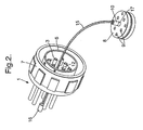
- Figs 2 and 3 where corresponding parts are designated by the same reference numeral as in Fig 1 , there is shown a modification to the assembly in which the housing 8 is tethered to the first connector part 1 by an elongate flexible member which in this example is a braided stainless steel wire 15.
- One end of the wire 15 is fixed to the end of the screw 10, for example by forming a small recess in the end of the screw and soldering the wire in the recess (see Fig 3 ).
- the other end of the wire 15 carries an end stop member 16 that is fixed to the wire 15 by crimping.
- a clip 17 is secured to the screw 10 to retain the screw assembly in position on the housing 8. (Such a clip is also present in the example shown in Fig 1 but is not visible.)
- the wire 15 is fixed to the end of the screw 10 and passes through the hole 11 which is in any case required for engaging the screw 10 when the housing is screwed onto the first connector part 1, the provision of the tether for the housing does not reduce the space available for optical fibre ends and thus does not reduce the capacity of the connector.
- the fibres may be arranged across the connector in a variety of patterns with some fibres close to the central axis of the connector and others towards the periphery. It may be noted that in Fig. 3 a section line is chosen through two of the fibres that are relatively close to the central axis of the connector.
- the housing 8 can be installed in the first connector part 1 by a user pulling the end stop member 16 to draw the housing into the connector part 1. Then the screw 10 can be screwed into the hole 11 and the two parts 1, 2 of the connector assembly secured together by screwing up the collar 7.
- the collar 7 is unscrewed, the screw 10 unscrewed and then the housing moved away from the first connector part 1 just as in the example of the connector of Fig 1 except that the housing 8 remains tethered to the wire 15 which is kept attached to the connector part 1 because the end stop member 16 is unable to pass through the hole 11. If it is required to detach the housing 8 completely, for example to replace or repair it, then the end stop member 16 can be cut off and a new member crimped to the end of the wire 15 in its place.
- Figs 2 and 3 show one particular example of the invention, it should be understood that many modifications may be made to the arrangement shown.
- the stainless steel wire may be replaced by other forms of cord or other elongate flexible member.
- Fibreglass braid, braided aramid yarn or other mixed or woven cords may be employed.
- the material of the cord is steel or another material, other methods of fixing the cord to the screw 10 and other methods of fixing the end stop member 16 to the cord may be employed, including, as well as crimping and soldering, adhesive bonding, screwing and tying.
- connector assemblies are of circular cross-section but it should be understood that the invention can be applied to assemblies of rectangular cross-section or indeed of other complex cross-sections and to assemblies with more or fewer fibre connections.
- a sealing member may be provided with the wire 15 slidably and sealingly received within the hole; such a member is shown in Fig. 3 and is indicated by the reference numeral 18.
- Another possibility is to provide a closed back cavity to the connecting part 1 and to accommodate the wire 15 in a tortuous shape within the cavity.
Landscapes
- Physics & Mathematics (AREA)
- General Physics & Mathematics (AREA)
- Optics & Photonics (AREA)
- Mechanical Coupling Of Light Guides (AREA)
Description
- This invention relates to a fibre optic connector assembly and more particularly to a fibre optic connector assembly that includes first and second connector parts that can be physically connected together and separated from one another, each connector part including a plurality of fibres each for optical connection to a respective fibre of the other part.
-
US 5,971,625 describes a fibre optic connector assembly having an adaptor to receive two ferrules in the connector. The adaptor allows this fibre optic connector assembly to be coupled to a further fibre optic connector. - In order to align fibres that are to be optically connected together, it has been proposed to provide a housing within the assembly with the housing defining a plurality of passageways for housing respective optical connections of the fibres of the first and second parts and for maintaining the fibres of each optical connection in alignment at the optical connector.
- In an assembly of the kind proposed above the optical connections are contained within the housing and are therefore not readily accessible for cleaning or other maintenance purposes. In order to overcome that problem it has been proposed to make the housing containing the optical connections removable so that the connections become readily accessible. An arrangement of this kind is described in
US 5,757,996 . - In the assembly described in
US 5,757,996 , the fibre optic connector assembly has two parts which can be physically connected together and separated from one another. Each of the first and second parts include two optical fibres each for optical connection to a respective fibre of the other part. - The first part of the connector assembly includes a housing, referred to in
US 5,757,996 as an alignment sleeve insert, which has passageways for housing two optical connections between the fibres. Immediately prior to physical connection of the first and second parts of the assembly, the fibres of the first part of the connector assembly extend into the passageways of the housing and, during the physical connection of the second part of the assembly to the first part, the fibres of the second part of the connector are inserted into the passageways of the housing which thereby serves to bring the fibres into aligned confronting relationship so that a good optical connection can be established. - When it is desired to gain access to the ends of the fibres, the first and second parts of the assembly are separated from one another. The ends of the fibres of the second part are then immediately accessible but the fibres of the first part are housed within the passageways of the housing and are therefore not readily accessible.
US 5,757,996 seeks to overcome the problem by allowing for the housing to be movable outwardly from the first part along a rod, sufficiently far that it moves clear of the ends of the fibres. Thereafter the housing can be rotated about the longitudal axis of the rod so that the ends of the fibres of the first part are accessible. - The arrangement of
US 5,757,996 is advantageous in providing a means for moving the housing to a position in which it causes much less obstruction to the free ends of the fibres of the first part, and also in retaining the housing physically connected to the first part of the assembly so that it cannot be lost. On the other hand the arrangement, even though it is complicated and requires a two stage movement of the housing, takes up space within the assembly (the space taken up by the rod) and even in its least obstructing position does impede access to a region of the interior of the first part of the connector as well. Those problems become more severe as the number of optical connections that it is desired to make within the assembly increases. - It is an object of the invention to provide an improved form of connector assembly for making optical connections between a plurality of fibres in which free access to the ends of each of the plurality of fibres is readily obtainable without parts of the connector being detached.
- According to the invention there is provided a fibre optic connector assembly including first and second connector parts that can be physically connected together and separated from one another, each connector part including a plurality of fibres, each for optical connection to a respective fibre of the other part, wherein a housing is provided within the assembly, the housing defining a plurality of passageways for housing respective optical connections of the fibres of the first and second connector parts and for maintaining the fibres of each optical connection in alignment, wherein the housing is tethered to the first connector part by an elongate flexible member.
- The fibre optic connector is preferably so arranged that one end of the elongate flexible member is able to be enclosed by the plurality of fibres of the first connector part. Yet more preferably the fibre optic connector is so arranged that one end of the elongate flexible member is able to be located co-axially with a longitudinal axis of the first connector part, said longitudinal axis being aligned substantially parallel to the ends of the plurality of fibres in the first connector part.
- The tether can be maintained during all routine operation of the assembly, including during separation of the housing from the first connector part to allow cleaning of the ends of the fibres of the first connector part. At the same time the tether can be sufficiently long that it is possible to avoid the housing obstructing the cleaning operation.
- The elongate flexible member is fixed at one end to the housing and extends from the housing to a free end, the free end of the elongate flexible member being arranged such that it is prevented from passing all the way through an opening in the first connector part.
- The end of the elongate flexible member opposite to the end fixed to the housing may be fixed to the first connector part (with a degree of slack in the elongate flexible member sufficient to allow the housing to be moved to a position where it does not obstruct cleaning) but it is preferably provided with a protuberance that is unable to fit through the opening of the wall of the first connector part. The elongate flexible member may be slidably located in the opening and the sliding connection may be sealed.
- In this simple manner the housing may be reliably retained with the first connector part, but without impeding cleaning of the ends of the fibres.
- The elongate flexible member is preferably in the form of a cord, although it may take other forms, such as that of an elongate strip if desired. The elongate flexible member may be made of any of a wide variety of materials including for example: stainless steel wire, fibreglass braid, braided aramid yarn or other materials.
- Preferably, the first connector part includes an open ended cavity, the fibres project into the cavity towards the open end thereof and the housing is movable between a first operative position in which it is at least partly in the cavity with the passageways of the housing receiving respective fibres therein and a second cleaning position in which it is out of the cavity, the housing being tethered to the first connector part in both the first operative position and the second cleaning position.
- Preferably the cavity is of generally cylindrical shape, the fibres project into the cavity towards the open end thereof in directions substantially parallel to the longitudinal axis of the generally cylindrical cavity and the housing extends across the open end of the cavity in its first operative position.
- Usually a fastening system additional to the tethering by the elongate flexible member, is provided, the fastening system serving to releasably secure the housing in a fixed relationship to the first connector part.
- The fastening system preferably comprises a screw threaded member that is screwed into a screw threaded hole in the first connector part. The elongate flexible member preferably is fixed to the screw threaded member and passes through the screw threaded hole when the screw threaded member is unscrewed.
- The fibres of the first connector part preferably comprise a multiplicity of fibres spaced around a central axis of the first connector part.
- The connector assembly may be of any of a wide variety of cross-sectional shapes but will usually be of either generally circular or generally rectangular cross-sectional shape. In the case of a connector assembly of generally circular shape, the fibres are preferably arranged around the central axis of each connector part in one or more rings with fibres within the same ring equiangularly spaced around the central axis of each connector part. Usually, each connector part will include at least five fibres.
- The present invention also provides a connector part for a fibre optic connector assembly, the connector part including a housing and the other features of the first connector part of the fibre optic connector assembly defined above.
- The invention is of particular advantage in the case of a connector assembly situated on an aircraft. It can be very costly if, during routine maintenance, at a location where a replacement housing is not readily available, the housing is lost, since the communication channels passing through the connector then become unusable. Accordingly, the present invention still further provides an aircraft including a fibre optic communications arrangement comprising at least one connector assembly as defined above.
- It should be understood that where reference is made to optical fibres of the first and second parts, those "fibres" will typically comprise, in the region of their connection, both the fibres themselves and other parts such as ferrules which may be provided around the fibres, especially in the region of their connection.
- It should also be understood that the 'housing' referred to above, fulfils the same function as the part referred to as the 'alignment sleeve insert' in
US 5,757,996 . The housing may also be referred to as an 'alignment block' and enables a good optical connection to be established between the optical fibres of the first and second connector parts. - By way of example an embodiment of the invention will now be described with reference to the accompanying drawings, of which:
- Figure 1
- is an exploded perspective view of a known fibre optic connector assembly,
- Figure 2
- is a perspective view of a first part of a connector assembly embodying the invention, and
- Figure 3
- is a sectional view of a part of the first connector part shown in
Figure 2 . - Referring first to
Fig 1 , the known fibre optic connector assembly comprises a first connector part 1 and asecond connector part 2. A plurality ofoptical fibres 3 terminate in the end of the first connector part 1 and the same number of fibres 4 terminate in the end of thesecond connector part 2. In the example shown there are sixteenfibres 3 and sixteen fibres 4. - The
second connector part 2 has a cylindrical connecting portion 5 which is externally screw threaded. The first connector part 1 has a cylindrical connectingportion 6, which fits inside the connecting portion 5 of the second connector part, and also has a rotatably mounted collar 7 which is internally screw threaded and can be screwed onto the connecting portion 5 of the second connector part when it is fitted over the connectingportion 6 of the first connector part. In that manner a reliable and secure physical connection can be established between the first and second connector parts. - It is also important to establish a reliable optical connection between fibres of the first and second connection parts and to that purpose it is important that a fibre of the first connection part is accurately aligned with a fibre of the second connection part to which it is to be optically connected. For that purpose the end portions of the fibres in each connection parts are fixed at predetermined locations and are relatively rigid as a result of each fibre end portion being surrounded by a respective ceramic ferrule. In addition to the provision of that ferrule, a
housing 8 is provided in which a plurality of ceramic sleeves 9, each defining a respective internal passageway, are fixed, each sleeve being dimensioned to receive in its passageway as a close fit the ends of an optical fibre of the first connector part 1 and an optical fibre of thesecond connector part 2. In that way a very precise alignment of the optical fibres can be obtained and therefore a good optical connection established between them. - The
housing 8 has asecuring screw 10 which, when the connector assembly is secured together, is screwed into a screw threadedhole 11 formed in afront face 12 of the first connector part 1. Thehousing 8 is then received within a cavity within the first connector part immediately in front of thefront face 12. Thescrew 10 and thehole 11 are disposed along the central longitudinal axis of the connector. As will be understood, the optical fibre ends of the first connector part project from thefront face 12 and project partway into the ceramic sleeves 9 of thehousing 8 from one side when theconnector parts 1, 2 are physically connected together. The optical fibre ends of the second connector part similarly project partway into the ceramic sleeves 9 of thehousing 8 from the other side when theconnector parts 1, 2 are physically connected together. In that way a reliable optical connection between fibre ends is established. - During use of the connector it may be necessary to dissemble the connector in order, for example, to clean the ends of the fibres. Such dissembly is easily accomplished by unscrewing the collar 7, after which the optical fibre ends of the
second connector part 2 are exposed and accessible, and then unscrewing thescrew 10 to allow thehousing 8 to be removed, after which the optical fibre ends of the first connector part 1 are exposed and accessible. While the first and second connector parts remain attached to the optical fibres, the housing is, in the arrangement shown inFig 1 , entirely unattached and there is therefore a risk of it being lost. That may be a particular problem if the connector is employed on an aircraft and the housing is lost during maintenance work at a remote location. - Referring now also to
Figs 2 and3 , where corresponding parts are designated by the same reference numeral as inFig 1 , there is shown a modification to the assembly in which thehousing 8 is tethered to the first connector part 1 by an elongate flexible member which in this example is a braidedstainless steel wire 15. One end of thewire 15 is fixed to the end of thescrew 10, for example by forming a small recess in the end of the screw and soldering the wire in the recess (seeFig 3 ). The other end of thewire 15 carries anend stop member 16 that is fixed to thewire 15 by crimping. Thewire 15 passes freely through thehole 11 in the centre of the connector part 1, but theend stop member 16 is of such a size that it cannot pass through thehole 11. Consequently although thehousing 8 can be moved to a position well clear of the optical fibre ends of the first connector part 1, it remains attached by thewire 15 and cannot therefore be lost. As shown inFig 2 , aclip 17 is secured to thescrew 10 to retain the screw assembly in position on thehousing 8. (Such a clip is also present in the example shown inFig 1 but is not visible.) - It may be noted that, because the
wire 15 is fixed to the end of thescrew 10 and passes through thehole 11 which is in any case required for engaging thescrew 10 when the housing is screwed onto the first connector part 1, the provision of the tether for the housing does not reduce the space available for optical fibre ends and thus does not reduce the capacity of the connector. Although in the example ofFigs 2 and3 , only eight fibres terminate in each connector part, it would also be possible for there to be, say, fifteen fibres terminating in each part. The fibres may be arranged across the connector in a variety of patterns with some fibres close to the central axis of the connector and others towards the periphery. It may be noted that inFig. 3 a section line is chosen through two of the fibres that are relatively close to the central axis of the connector. - Starting from the position shown in
Fig 2 , thehousing 8 can be installed in the first connector part 1 by a user pulling theend stop member 16 to draw the housing into the connector part 1. Then thescrew 10 can be screwed into thehole 11 and the twoparts 1, 2 of the connector assembly secured together by screwing up the collar 7. When dissembling, the collar 7 is unscrewed, thescrew 10 unscrewed and then the housing moved away from the first connector part 1 just as in the example of the connector ofFig 1 except that thehousing 8 remains tethered to thewire 15 which is kept attached to the connector part 1 because theend stop member 16 is unable to pass through thehole 11. If it is required to detach thehousing 8 completely, for example to replace or repair it, then theend stop member 16 can be cut off and a new member crimped to the end of thewire 15 in its place. - Whilst
Figs 2 and3 show one particular example of the invention, it should be understood that many modifications may be made to the arrangement shown. For example, the stainless steel wire may be replaced by other forms of cord or other elongate flexible member. Fibreglass braid, braided aramid yarn or other mixed or woven cords may be employed. Whether or not the material of the cord is steel or another material, other methods of fixing the cord to thescrew 10 and other methods of fixing theend stop member 16 to the cord may be employed, including, as well as crimping and soldering, adhesive bonding, screwing and tying. - In the examples shown the connector assemblies are of circular cross-section but it should be understood that the invention can be applied to assemblies of rectangular cross-section or indeed of other complex cross-sections and to assemblies with more or fewer fibre connections.
- In some cases it may be desirable for the interior of the connector assembly to be sealed. In such a case, a sealing member may be provided with the
wire 15 slidably and sealingly received within the hole; such a member is shown inFig. 3 and is indicated by thereference numeral 18. Another possibility is to provide a closed back cavity to the connecting part 1 and to accommodate thewire 15 in a tortuous shape within the cavity.
Claims (11)
- A fibre optic connector assembly including first and second parts that can be physically connected together and separated from one another, each connector part including a plurality of fibres, each for optical connection to a respective fibre of the other part, wherein a housing is provided within the assembly, the housing defining a plurality of passageways for housing respective optical connections of the fibres of the first and second connector parts and for maintaining the fibres of each optical connection in alignment, characterised in that the housing is tethered to the first connector part by an elongate flexible member, the elongate flexible member being fixed at one end to the housing, and the elongate flexible member extending from the housing to a free end, the free end of the elongate flexible member being arranged such that it is prevented from passing all the way through an opening in the first connector part.
- A fibre optic connector assembly according to claim 1, in which the end of the elongate flexible member opposite to the end fixed to the housing is provided with a protuberance that is unable to fit through the opening in the first connector part.
- A fibre optic connector assembly according to claim 1 or 2, in which the elongate flexible member comprises a cord.
- A fibre optic connector assembly according to claim 3, in which the first connector part includes an open ended cavity, the fibres project into the cavity towards the open end thereof and the housing is movable between a first operative position in which it is at least partly in the cavity with the passageways of the housing receiving respective fibres therein and a second cleaning position in which it is out of the cavity, the housing being tethered to the first connector part in both the first operative position and the second cleaning position.
- A fibre optic connector assembly according to claim 4, in which the cavity is of generally cylindrical shape, the fibres project into the cavity towards the open end thereof in directions substantially parallel to the longitudinal axis of the generally cylindrical cavity, and the housing extends across the open end of cavity in its first operative position.
- A fibre optic connector assembly according to any preceding claim, in which a fastening system, additional to the tethering by the elongate flexible member, is provided, the fastening system serving to detachably secure the housing in a fixed relationship to the first connector part.
- A fibre optic connector assembly according to claim 6, in which the fastening system comprises a screw threaded member that is screwed into a screw threaded hole in the first connector part.
- A fibre optic connector assembly according to claim 7, in which the elongate flexible member is fixed to the screw threaded member and passes through the screw threaded hole when the screw threaded member is unscrewed.
- A fibre optic connector assembly according to any preceding claim, in which the fibres of the first connector part comprise a multiplicity of fibres spaced around a central axis of the first connector part.
- A connector part and a housing for use as the first connector part and the housing in the fibre optic connector assembly according to any preceding claim, the connector part including a plurality of fibres, each for optical connection to a respective fibre of another part, and the housing defining a plurality of passageways for housing optical connections of the fibres of the connector part, and for maintaining the fibres of each optical connection in alignment,
characterised in that the housing is tethered to the connector part by an elongate flexible member, the elongate flexible member being fixed at one end to the housing, and the elongate flexible member extending from the housing to a free end, the free end of the elongate flexible member being arranged such that it is prevented from passing all the way through an opening in the connector part. - An aircraft including a fibre optic communications arrangement comprising at least one connector assembly according to any of claims 1 to 9.
Priority Applications (1)
| Application Number | Priority Date | Filing Date | Title |
|---|---|---|---|
| EP04730294.8A EP1620759B1 (en) | 2003-05-02 | 2004-04-29 | Fiber optic connector |
Applications Claiming Priority (4)
| Application Number | Priority Date | Filing Date | Title |
|---|---|---|---|
| GB0310206A GB0310206D0 (en) | 2003-05-02 | 2003-05-02 | Fibre optic connector assemblies |
| EP03252861 | 2003-05-07 | ||
| EP04730294.8A EP1620759B1 (en) | 2003-05-02 | 2004-04-29 | Fiber optic connector |
| PCT/GB2004/001858 WO2004097484A1 (en) | 2003-05-02 | 2004-04-29 | Fibre optic connector |
Publications (2)
| Publication Number | Publication Date |
|---|---|
| EP1620759A1 EP1620759A1 (en) | 2006-02-01 |
| EP1620759B1 true EP1620759B1 (en) | 2013-06-05 |
Family
ID=33420593
Family Applications (1)
| Application Number | Title | Priority Date | Filing Date |
|---|---|---|---|
| EP04730294.8A Expired - Lifetime EP1620759B1 (en) | 2003-05-02 | 2004-04-29 | Fiber optic connector |
Country Status (3)
| Country | Link |
|---|---|
| US (1) | US7237965B2 (en) |
| EP (1) | EP1620759B1 (en) |
| WO (1) | WO2004097484A1 (en) |
Families Citing this family (4)
| Publication number | Priority date | Publication date | Assignee | Title |
|---|---|---|---|---|
| DE102009008506B3 (en) * | 2009-02-12 | 2010-08-26 | Airbus Deutschland Gmbh | Cable connection device, thus provided line feedthrough and use of the same |
| JP5623621B2 (en) * | 2010-03-19 | 2014-11-12 | コーニング インコーポレイテッド | Optical fiber interface device with positionable cover |
| US8727636B2 (en) * | 2010-03-19 | 2014-05-20 | Corning Incorporated | Fiber optic interface device with positionable cleaning cover |
| USD770384S1 (en) * | 2015-02-05 | 2016-11-01 | Abb Ab | Connector |
Family Cites Families (8)
| Publication number | Priority date | Publication date | Assignee | Title |
|---|---|---|---|---|
| US2962688A (en) | 1957-05-31 | 1960-11-29 | Siemens And Halske Ag Berlin A | Plug-in cable connector |
| US4645295A (en) | 1980-02-04 | 1987-02-24 | Allied Corporation | Fiber optic connector |
| US4979792A (en) | 1989-08-21 | 1990-12-25 | Amp Incorporated | Means for keeping keying elements with a connector assembly |
| US5202949A (en) | 1992-04-30 | 1993-04-13 | Amp Incorporated | Dust cover for fiber optic ferrules of optical fiber connectors |
| US5408557A (en) * | 1994-04-20 | 1995-04-18 | Hsu; Chung-Tang | FC-type optical fiber cable connector's adaptor |
| GB2311380B (en) | 1996-03-22 | 2000-02-02 | Deutsch Limited | Optical fibre connector |
| US5692080A (en) | 1996-10-03 | 1997-11-25 | Adc Telecommunications, Inc. | Double ferrule SC connector and adapter |
| US6394661B1 (en) | 1999-02-09 | 2002-05-28 | Fiber Systems International | Fiber optic connector having receptacle housing for radially aligning mating inserts |
-
2004
- 2004-04-29 WO PCT/GB2004/001858 patent/WO2004097484A1/en not_active Ceased
- 2004-04-29 EP EP04730294.8A patent/EP1620759B1/en not_active Expired - Lifetime
- 2004-04-29 US US10/554,990 patent/US7237965B2/en not_active Expired - Fee Related
Also Published As
| Publication number | Publication date |
|---|---|
| US7237965B2 (en) | 2007-07-03 |
| EP1620759A1 (en) | 2006-02-01 |
| US20060239620A1 (en) | 2006-10-26 |
| WO2004097484A1 (en) | 2004-11-11 |
Similar Documents
| Publication | Publication Date | Title |
|---|---|---|
| KR100339725B1 (en) | Optical connector | |
| US6565262B2 (en) | Trigger mechanism, optical cable connector including same, and method of assembling an optical cable connector | |
| EP2686724B1 (en) | Fiber optic connector and cable assembly | |
| EP2249581B1 (en) | Fibre optic assembly including rear connectors | |
| KR101590891B1 (en) | Optical communication connector | |
| RU2134895C1 (en) | Incorporated module fibre-optical connection system | |
| EP2440960B1 (en) | Pre-connectorized optical fibre cable, and kit for the deployment thereof | |
| EP3907541A1 (en) | Fiber optic connector | |
| KR100850925B1 (en) | Fiber Optic Integrated Fiber Optic Tap | |
| US20140050443A1 (en) | Reconfigurable polarity detachable connector assembly | |
| WO2018226959A1 (en) | Fiber optic adapter and cassette | |
| CN109856731A (en) | The method of the fiber optic connector and interconversion of changeable yin-yang configuration | |
| US11822131B2 (en) | Protective cap for an optical fiber connector | |
| DE69838197T2 (en) | Optical connector | |
| CN104516060A (en) | Connector housing for securing optical cables and methods of use and manufacture thereof | |
| JP2006039560A (en) | Optical fiber connector | |
| CN208488569U (en) | Modular open air optical fiber connector | |
| US7237965B2 (en) | Fibre optic connector | |
| EP3537195A2 (en) | Lc-type simplified connector plug and optical connector device using the plug | |
| US6848833B1 (en) | Replaceable fiber optic interface module | |
| US20170315307A1 (en) | Optical sub-assembly for compact optical interconnections | |
| EP4341736B1 (en) | Assemblies for pulling, pushing, or blowing a plurality of preterminated fiber optic cables through a duct and assembling a fiber optic connector including the preterminated fiber optic cable after being pulled, pushed, or blown through the duct | |
| CN109164540A (en) | A kind of optical fiber jointing and the tail optical fiber using the connector | |
| CN110231684A (en) | Modular open air optical fiber connector and its assemble method | |
| US20250172764A1 (en) | Fiber optic connector |
Legal Events
| Date | Code | Title | Description |
|---|---|---|---|
| PUAI | Public reference made under article 153(3) epc to a published international application that has entered the european phase |
Free format text: ORIGINAL CODE: 0009012 |
|
| 17P | Request for examination filed |
Effective date: 20051115 |
|
| AK | Designated contracting states |
Kind code of ref document: A1 Designated state(s): DE ES FR GB IT |
|
| DAX | Request for extension of the european patent (deleted) | ||
| RBV | Designated contracting states (corrected) |
Designated state(s): DE ES FR GB IT |
|
| RAP1 | Party data changed (applicant data changed or rights of an application transferred) |
Owner name: AIRBUS OPERATIONS LIMITED |
|
| 17Q | First examination report despatched |
Effective date: 20100604 |
|
| GRAP | Despatch of communication of intention to grant a patent |
Free format text: ORIGINAL CODE: EPIDOSNIGR1 |
|
| RAP1 | Party data changed (applicant data changed or rights of an application transferred) |
Owner name: AIRBUS OPERATIONS LIMITED |
|
| GRAS | Grant fee paid |
Free format text: ORIGINAL CODE: EPIDOSNIGR3 |
|
| GRAA | (expected) grant |
Free format text: ORIGINAL CODE: 0009210 |
|
| AK | Designated contracting states |
Kind code of ref document: B1 Designated state(s): DE ES FR GB IT |
|
| REG | Reference to a national code |
Ref country code: GB Ref legal event code: FG4D |
|
| REG | Reference to a national code |
Ref country code: DE Ref legal event code: R096 Ref document number: 602004042357 Country of ref document: DE Effective date: 20130801 |
|
| PG25 | Lapsed in a contracting state [announced via postgrant information from national office to epo] |
Ref country code: ES Free format text: LAPSE BECAUSE OF FAILURE TO SUBMIT A TRANSLATION OF THE DESCRIPTION OR TO PAY THE FEE WITHIN THE PRESCRIBED TIME-LIMIT Effective date: 20130916 |
|
| PLBE | No opposition filed within time limit |
Free format text: ORIGINAL CODE: 0009261 |
|
| STAA | Information on the status of an ep patent application or granted ep patent |
Free format text: STATUS: NO OPPOSITION FILED WITHIN TIME LIMIT |
|
| 26N | No opposition filed |
Effective date: 20140306 |
|
| PG25 | Lapsed in a contracting state [announced via postgrant information from national office to epo] |
Ref country code: IT Free format text: LAPSE BECAUSE OF FAILURE TO SUBMIT A TRANSLATION OF THE DESCRIPTION OR TO PAY THE FEE WITHIN THE PRESCRIBED TIME-LIMIT Effective date: 20130605 |
|
| REG | Reference to a national code |
Ref country code: DE Ref legal event code: R097 Ref document number: 602004042357 Country of ref document: DE Effective date: 20140306 |
|
| REG | Reference to a national code |
Ref country code: FR Ref legal event code: PLFP Year of fee payment: 12 |
|
| PGFP | Annual fee paid to national office [announced via postgrant information from national office to epo] |
Ref country code: GB Payment date: 20150420 Year of fee payment: 12 Ref country code: DE Payment date: 20150421 Year of fee payment: 12 |
|
| PGFP | Annual fee paid to national office [announced via postgrant information from national office to epo] |
Ref country code: FR Payment date: 20150421 Year of fee payment: 12 |
|
| REG | Reference to a national code |
Ref country code: DE Ref legal event code: R119 Ref document number: 602004042357 Country of ref document: DE |
|
| GBPC | Gb: european patent ceased through non-payment of renewal fee |
Effective date: 20160429 |
|
| REG | Reference to a national code |
Ref country code: FR Ref legal event code: ST Effective date: 20161230 |
|
| PG25 | Lapsed in a contracting state [announced via postgrant information from national office to epo] |
Ref country code: FR Free format text: LAPSE BECAUSE OF NON-PAYMENT OF DUE FEES Effective date: 20160502 Ref country code: GB Free format text: LAPSE BECAUSE OF NON-PAYMENT OF DUE FEES Effective date: 20160429 Ref country code: DE Free format text: LAPSE BECAUSE OF NON-PAYMENT OF DUE FEES Effective date: 20161101 |