EP1620232B1 - Schraubenschlüssel - Google Patents
Schraubenschlüssel Download PDFInfo
- Publication number
- EP1620232B1 EP1620232B1 EP04723258A EP04723258A EP1620232B1 EP 1620232 B1 EP1620232 B1 EP 1620232B1 EP 04723258 A EP04723258 A EP 04723258A EP 04723258 A EP04723258 A EP 04723258A EP 1620232 B1 EP1620232 B1 EP 1620232B1
- Authority
- EP
- European Patent Office
- Prior art keywords
- wrench
- handle
- split ring
- head portion
- protrusion
- Prior art date
- Legal status (The legal status is an assumption and is not a legal conclusion. Google has not performed a legal analysis and makes no representation as to the accuracy of the status listed.)
- Expired - Lifetime
Links
- 230000006835 compression Effects 0.000 claims description 10
- 238000007906 compression Methods 0.000 claims description 10
- 230000000295 complement effect Effects 0.000 claims description 9
- 230000008878 coupling Effects 0.000 claims description 5
- 238000010168 coupling process Methods 0.000 claims description 5
- 238000005859 coupling reaction Methods 0.000 claims description 5
- 230000000694 effects Effects 0.000 description 3
- 230000007246 mechanism Effects 0.000 description 3
- 238000010276 construction Methods 0.000 description 2
- 229910000831 Steel Inorganic materials 0.000 description 1
- 210000000078 claw Anatomy 0.000 description 1
- 230000007797 corrosion Effects 0.000 description 1
- 238000005260 corrosion Methods 0.000 description 1
- 230000037431 insertion Effects 0.000 description 1
- 238000003780 insertion Methods 0.000 description 1
- 238000000926 separation method Methods 0.000 description 1
- 239000010959 steel Substances 0.000 description 1
Images


Classifications
-
- B—PERFORMING OPERATIONS; TRANSPORTING
- B25—HAND TOOLS; PORTABLE POWER-DRIVEN TOOLS; MANIPULATORS
- B25B—TOOLS OR BENCH DEVICES NOT OTHERWISE PROVIDED FOR, FOR FASTENING, CONNECTING, DISENGAGING OR HOLDING
- B25B13/00—Spanners; Wrenches
- B25B13/46—Spanners; Wrenches of the ratchet type, for providing a free return stroke of the handle
- B25B13/461—Spanners; Wrenches of the ratchet type, for providing a free return stroke of the handle with concentric driving and driven member
- B25B13/462—Spanners; Wrenches of the ratchet type, for providing a free return stroke of the handle with concentric driving and driven member the ratchet parts engaging in a direction radial to the tool operating axis
-
- B—PERFORMING OPERATIONS; TRANSPORTING
- B25—HAND TOOLS; PORTABLE POWER-DRIVEN TOOLS; MANIPULATORS
- B25B—TOOLS OR BENCH DEVICES NOT OTHERWISE PROVIDED FOR, FOR FASTENING, CONNECTING, DISENGAGING OR HOLDING
- B25B13/00—Spanners; Wrenches
- B25B13/02—Spanners; Wrenches with rigid jaws
- B25B13/04—Spanners; Wrenches with rigid jaws of ring jaw type
-
- B—PERFORMING OPERATIONS; TRANSPORTING
- B25—HAND TOOLS; PORTABLE POWER-DRIVEN TOOLS; MANIPULATORS
- B25B—TOOLS OR BENCH DEVICES NOT OTHERWISE PROVIDED FOR, FOR FASTENING, CONNECTING, DISENGAGING OR HOLDING
- B25B13/00—Spanners; Wrenches
- B25B13/02—Spanners; Wrenches with rigid jaws
- B25B13/06—Spanners; Wrenches with rigid jaws of socket type
-
- B—PERFORMING OPERATIONS; TRANSPORTING
- B25—HAND TOOLS; PORTABLE POWER-DRIVEN TOOLS; MANIPULATORS
- B25B—TOOLS OR BENCH DEVICES NOT OTHERWISE PROVIDED FOR, FOR FASTENING, CONNECTING, DISENGAGING OR HOLDING
- B25B13/00—Spanners; Wrenches
- B25B13/46—Spanners; Wrenches of the ratchet type, for providing a free return stroke of the handle
Definitions
- the present invention relates to a wrench according to the preamble of claim 1.
- a wrench has at least a one way operation and more particularly, though not exclusively, concerns a tool similar in operation to a ratchet like tool having a ratchet bar.
- Such a wrench is known from BE 384 487 .
- Ratchet tools are well known and are a tool suitable for applying torque to a fastener such as a nut, bolt or screw, via an appropriate drive socket (hereinafter also referred to as a fastening device) having a square drive recess which receives a square peg of a ratchet bar, for the purpose of tightening or slackening the fastener.
- a fastening device having a square drive recess which receives a square peg of a ratchet bar, for the purpose of tightening or slackening the fastener.
- the wrench or ratchet tool is movable relative to the fastening device in one direction only opposite to that direction in which torque is applied.
- Motion between the ratchet bar and the fastening device in the opposite direction is achieved by a set of angular teeth, which co-operate with a pawl to create a locking motion in the one direction only for applying torque and free movement in the opposite direction.
- the operation of the fastening device and fastener via a ratchet bar is much more convenient in restricted space situations than the use of a fixed bar operated socket because there is seldom a requirement to remove and reattach the fastening device operating the fastener.
- BE 384 487 and GB 0 387 590 describes a wrench comprising a handle that is pivotably coupled to a head portion. More specifically, the wrench of BE 384 487 comprises a handle portion that swivels around a pivot, with one or more handle cams acting against the open end of the split head portion. The residual strength of the split head portion at rest of the corresponding handle cam is adjusted by grab screws onto a teeter board or sccsaw plates around a fixed pin. Therefore, in use, there is a gap induced between the split head portion of the end cams and one of the handle cams.
- a wrench comprising a head portion defining an aperture, a split ring sprung into said aperture and having spaced-apart end portions and a handle pivotally coupled to said head portion for moving said end portions together, said split ring having an abutment portion and a camming portion, said abutment portion being adapted to cooperate with a complementary abutment portion formed in said head portion to limit the available rotation of the split ring within the aperture, and said camming portion being adapted to cooperate with a complementary part on said pivotal lever for moving the spaced-apart end portions of the split ring towards each other when said abutment portion of the split ring is abutting the complementary abutment portion on the head portion, wherein said aperture is a circular aperture and the wrench further comprises spring means biasing said handle in a sense to close said spaced apart end portions of the split pin together with a force greater than the spring force developed by the split ring itself.
- the spring means biasing the handle is located in the handle at the coupling between the head portion and the handle.
- the spring means is located in a passage extending through the coupling and complimentary apertures in the handle.
- Opposed ends of the spring means may be associated with detent means.
- the detent means comprises a ball located at each of the two opposed ends of the spring means, respectively, for engagement with a respective protrusion on the head portion.
- Each protrusion may extend towards the other in an elongate slotted portion of the head portion in which an end portion of the handle is coupled to the head portion.
- the wrench may include two recesses on either side of each protrusion for receiving therein a respective one of the balls when the handle is in a drive or a reverse drive position.
- the spring means is conveniently a compression spring.
- the complimentary part on said pivotal lever for moving the spaced apart end portions of the split ring towards each other comprises end walls of a slot at the inner-most end of the handle within the head portion, the slot extending in a transverse direction to a longitudinal axis of the handle.
- the spaced apart end portions of the split ring may comprise a land extending in both a radially outward direction and a circumferential direction, to define a common protrusion contiguous the split in the ring and the abutment portion at the circumferentially opposed end of the land to the respective camming portion, wherein the camming portions project into the transverse slot of the handle.
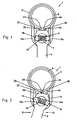
- a wrench having a clamp drive socket bar (1) which includes a head portion (2) formed of steel for example and coupled with an elongate handle (3) for applying torque to a drive spigot (4a) of a socket (4) having an external cylindrical drive surface (4b).
- a resilient split ring (5) is spring fitted within the head portion (2) and is so sized that in an inherently expanded condition the split ring engages, in a complementary manner, internal surface (6) of the head portion (2).
- a pivot or fulcrum pin (7) is mounted in opposed apertures (8) on opposite sides of the head portion (2) and also extends through aperture (9) through one end (10) of the handle (3) to which the head portion (2) is attached for coupling the head portion (2) and handle (3) so as to be pivotable one relative to the other.
- the pivot pin (7) has a diametrically extending cylindrical aperture (11) therethrough.
- a compression spring (15) and a ball (16) at each opposite end of the spring are located in the cylindrical aperture (11) and extend into diametrically opposed apertures (17) on transverse faces (18) of end (10) of handle (3).
- the head portion (2) is shown in Fig. 4 to be of a two part construction to sandwich therebetween the resilient split ring portion (5) in a substantially cylindrical part (2a).
- a slotted part (2b) extends radially outwardly from cylindrical part (2a) to receive end (10) of handle (3) within the slotted part (2b).
- Parallel opposed surfaces (19) extend in a direction parallel to the central rotational axis (20) of aperture (21) through head portion (2) for receiving spigot (4a) of the socket fastener device (4).
- the parallel surfaces (19) are each provided with a smooth curved protrusion (19a) aligned with and directed towards the other.
- the protrusions are located as shown in Fig. 1 to act simultaneously on opposed balls (16) to compress spring (15).
- the flexible ring (5) has a generally radially extending gap (30) between opposed ring ends (31) and (32) thereof.
- An elongate camming arm (33) extends in a radial direction outwardly from ring end (31) and a similar camming arm (34) extends in a radial direction outwardly from ring end (32).
- the two camming arms (31) and (32) are closely spaced one from the other by gap (30) in an inoperative condition of the clamp drive socket bar (1) as shown in Fig. 1 .
- a radially outwardly extending land (35,36) extends a short distance circumferentially from arms (33, 34), respectively.
- the lands extend between the opposed parallel surfaces (19) defining the slot in the slotted part (2b) of the head portion.
- the lands each have a flat end abutment surface (37,38) remote from camming arms (33,34), respectively, for engaging when necessary respective surfaces (19) of the slotted portion (2b) of the head.
- Abutment surfaces (37,38) are both engagable with the respective surfaces (19) in the central non-operative position of the wrench as shown in Fig. 1 .
- Complementary surfaces (39,40) at the outermost end (10) of the handle (3) extend in a direction parallel to the longitudinal direction of the handle (3) and in use engage camming arms (33,34), respectively, as necessary, to begin to close gap (30) and subsequently clamp firmly spigot (4a) of socket fastening device (4) to rotate the same.
- Fig. 4 shows a washer (45) and a screw (46) being used to hold the pivot pin (7) in place relative to the head portion 2.
- the washer and screw, with pivot pin (7) serve also to hold the two parts of the head portion (2) together.
- the pivot pin (7) is simply replaced by a pin having a friction fit for example to help hold the two parts of the housing together. Otherwise the embodiment described in Fig. 5 operates in the same manner as described above in regard to the specific embodiment of Figs. 1 to 4 .
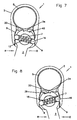
- Figs. 6 to 8 illustrate yet another embodiment in accordance with the present invention.
- the construction shown is slightly different than previously shown in Figs. 1 to 4 or Fig. 5 .
- the operation of the wrench of Figs. 6 to 8 is substantially identical to what has previously been described above.
- the physical differences amount to the end (10) of the handle (3) being substantially annular with the pivot pin (7) occupying the central aperture of the annulus.
- the surfaces (19) of the slotted portion (2b) are no longer parallel but are curved to provide a more pronounced recess on either side of the protrusions thereby to ensure a more positive and faster snap action than the previously described embodiments.
- the wrench device of the present invention can operate efficiently to tighten a fastener in situations where there is little space to operate without the need to rely on ratchet teeth.
- the resilient split ring (5) operates immediately to grip the drive spigot of the fastening device when the handle is moved in direction D. Furthermore, torque increases to grip the drive spigot tighter the more the handle is forced in direction D. Therefore, the chance of slippage is removed whether the drive occurs between two cylindrical surfaces or hexagonal surfaces. Additionally, the wrench can be applied directionally to fasteners of various sizes using the one flexible ring.
- the handle When it is necessary to obtain free reverse rotation of the handle so that further drive forces can subsequently be applied, the handle is movable in the reverse direction R immediately releasing the split ring which begins to open under its inherent resilience. Thereby, pressure is released upon the drive spigot of the socket fastening device and the whole wrench can move freely about the spigot to provide sufficient room to apply drive pressure to tighten a fastener. Furthermore, as the reverse force R is released from the handle the compression spring acts as described above to force the handle in the drive D direction and to move the camming means in a direction to close the gap in the split ring thereby gripping the spigot tightly prior to drive torque being applied to further tighten the fastener. Therefore, the compression spring and protrusions provide in effect an automatic clamping upon the spigot in either drive D or reverse drive R directions.
- the wrench does not have to be removed from the socket spigot but the head portion held while the handle is moved over centre in reverse direction R, when the abutments (37,38) on the split ring both engage respective surfaces (19) of the head portion and the detent balls (16) are forced pass the protrusion in opposite directions.
- the compression spring (15) forces the balls down the side walls of the protrusions into a recess on either side thereof respectively at the base of the protrusions and in the inside wall (19) defining the slotted portion of the head portion (2).
- camming portion (34) is engaged by end surface (40) to move camming portion (34) towards the camming portion (33) to close the split ring about the spigot (4a) of the socket (4) whereupon operation for releasing a fastener is the same as for tightening the fastener as described above.
- the handle (3) may be in a central position in which the compression spring is fully compressed and the balls (16) are substantially within recess (11) and apertures (17), and both press outwardly on opposed surfaces (19), respectively.
Claims (13)
- Schraubenschlüssel, der Folgendes umfasst: einen Kopfabschnitt (2), der eine Öffnung definiert; einen Spaltring (5), der federnd in die Öffnung eingesetzt ist und voneinander beabstandete Endabschnitte aufweist; und einen Handgriff (3), der an dem Kopfabschnitt (2) angelenkt ist, um die Endabschnitte zusammenzuführen, wobei der Spaltring (5) einen Endanschlagabschnitt (37, 38) und einen Nockenabschnitt (33, 34) aufweist, wobei der Endanschlagabschnitt (37, 38) dafür geeignet ist, mit einem komplementären Endanschlagabschnitt (19) zusammenzuwirken, der in dem Kopfabschnitt (2) ausgebildet ist, um die verfügbare Drehbewegung des Spaltrings (5) innerhalb der Öffnung (2) zu begrenzen, wobei der Nockenabschnitt (33, 34) dafür geeignet ist, mit einem komplementären Teil (39, 40) an dem Schwenkhebel zusammenzuwirken, um die voneinander beabstandeten Endabschnitte des Spaltrings (5) zusammenzuführen, wenn der Endanschlagabschnitt (37, 38) des Spaltrings (5) an dem komplementären Endanschlagabschnitt (19) an dem Kopfabschnitt (2) anliegt, dadurch gekennzeichnet, dass die Öffnung eine kreisrunde Öffnung ist und dass der Schraubenschlüssel des Weiteren ein Federmittel (15) umfasst, das den Handgriff in einer solchen Richtung vorspannt, dass die voneinander beabstandeten Endabschnitte des Spaltrings (5) mit einer Kraft gegeneinander geschlossen werden, die größer als die Federkraft ist, die durch den Spaltring (5) selbst verursacht wird.
- Schraubenschlüssel nach Anspruch 1, wobei das Federmittel (15), das den Handgriff (13) vorspannt, in der Kupplung zwischen dem Kopfabschnitt (2) und dem Handgriff angeordnet ist.
- Schraubenschlüssel nach Anspruch 2, wobei das Federmittel in einem Durchhang (11) angeordnet ist, der sich durch die Kupplung und komplementäre Öffnungen (17) in dem Handgriff erstreckt.
- Schraubenschlüssel nach Anspruch 2 oder 3, wobei entgegengesetzte Enden des Federmittels (15) einem Arretierungsmittel zugeordnet sind.
- Schraubenschlüssel nach Anspruch 4, wobei das Arretierungsmittel eine Kugel (16) umfasst, die jeweils an jedem von zwei gegenüberliegenden Enden des Federmittels (15) angeordnet ist, um einen jeweiligen Vorsprung (19a) an dem Kopfabschnitt (2) in Eingriff zu nehmen.
- Schraubenschlüssel nach Anspruch 5, wobei sich jeder Vorsprung (19a) in einem länglichen geschlitzten Abschnitt des Kopfabschnitts (2), in dem ein Endabschnitt des Handgriffs (3) mit dem Kopfabschnitt (2) gekoppelt ist, in Richtung des anderen erstreckt.
- Schraubenschlüssel nach Anspruch 5 oder 6, der zwei Aussparungen auf jeder Seite jedes Vorsprungs (19a) enthält, in denen eine jeweilige der Kugeln (16) aufgenommen wird, wenn sich der Handgriff (3) in einer Antriebs- oder Umkehrantriebsposition befindet.
- Schraubenschlüssel nach einem der Ansprüche 5 bis 7, wobei sich jeder Vorsprung (19a) von einer planaren Seitenwand erstreckt.
- Schraubenschlüssel nach einem der Ansprüche 5 bis 7, wobei sich jeder Vorsprung (19a) von einer planaren Seitenwand erstreckt, die eine Aussparung auf jeder Seite des Vorsprungs (19a) aufweist.
- Schraubenschlüssel nach einem der Ansprüche 5 bis 7, wobei die Seitenwände, von denen sich der Vorsprung (19a) erstreckt, im Wesentlichen gekrümmt sind.
- Schraubenschlüssel nach einem der vorangehenden Ansprüche, wobei das Federmittel (15) eine Kompressionsfeder ist.
- Schraubenschlüssel nach einem der vorangehenden Ansprüche, wobei der komplementäre Teil (39, 40) an dem Schwenkhebel, der zum Bewegen der voneinander beabstandeten Endabschnitte des Spaltrings (15) in Richtung aufeinander dient, Endwände eines Schlitzes am innersten Ende des Handgriffs innerhalb des Kopfabschnitts (2) umfasst, wobei sich der Schlitz in einer Querrichtung relativ zu einer Längsachse des Handgriffs (3) erstreckt.
- Schraubenschlüssel nach Anspruch 9, wobei die voneinander beabstandeten Endabschnitte des Spaltrings (5) jeweils einen Absatz (35, 36) umfassen, der sich sowohl in einer radial nach außen weisenden Richtung als auch in einer Umfangsrichtung erstreckt, um einen Nockenarm (33, 34) zu definieren, der an den Spalt in dem Spaltring (5) und den Endanschlagabschnitt (37, 38) an dem umfänglich entgegengesetzten Ende des Absatzes (35, 36) zu dem jeweiligen Nockenarm (33, 34) angrenzt, wobei die Nockenarme (33, 34) in den Querschlitz des Handgriffs (3) hinein ragen, um bei Bedarf durch eine Endwand des Querschlitzes in Eingriff genommen zu werden.
Applications Claiming Priority (2)
| Application Number | Priority Date | Filing Date | Title |
|---|---|---|---|
| GB0306826A GB2399782B (en) | 2003-03-25 | 2003-03-25 | A wrench |
| PCT/GB2004/001312 WO2004085116A1 (en) | 2003-03-25 | 2004-03-25 | A wrench |
Publications (3)
| Publication Number | Publication Date |
|---|---|
| EP1620232A1 EP1620232A1 (de) | 2006-02-01 |
| EP1620232B1 true EP1620232B1 (de) | 2009-09-09 |
| EP1620232B8 EP1620232B8 (de) | 2009-10-14 |
Family
ID=9955486
Family Applications (1)
| Application Number | Title | Priority Date | Filing Date |
|---|---|---|---|
| EP04723258A Expired - Lifetime EP1620232B8 (de) | 2003-03-25 | 2004-03-25 | Schraubenschlüssel |
Country Status (8)
| Country | Link |
|---|---|
| US (1) | US7197964B2 (de) |
| EP (1) | EP1620232B8 (de) |
| CN (1) | CN100434238C (de) |
| AT (1) | ATE442229T1 (de) |
| DE (1) | DE602004023076D1 (de) |
| ES (1) | ES2330635T3 (de) |
| GB (1) | GB2399782B (de) |
| WO (1) | WO2004085116A1 (de) |
Families Citing this family (21)
| Publication number | Priority date | Publication date | Assignee | Title |
|---|---|---|---|---|
| GB0621027D0 (en) | 2006-10-23 | 2006-11-29 | Buchanan Nigel A | Last change wrench |
| US7765896B1 (en) * | 2008-08-05 | 2010-08-03 | Wei-Chu Chen | Reversible ratchet wrench whose operation directions are changed easily and quickly |
| EP2601016A2 (de) | 2010-08-06 | 2013-06-12 | American Grease Stick Company | Schlüssel mit einem auslöser |
| GB201105123D0 (en) | 2010-08-30 | 2011-05-11 | Amercan Grease Stick Company | Wrench ratchet mechanisms and wrenches |
| USD717619S1 (en) | 2013-04-01 | 2014-11-18 | Ridge Tool Company | Tool handle |
| USD742707S1 (en) | 2013-04-01 | 2015-11-10 | Ridge Tool Company | Tool head |
| USD739192S1 (en) | 2013-04-01 | 2015-09-22 | Ridge Tool Company | Insert for tool |
| US9205539B2 (en) | 2013-04-01 | 2015-12-08 | Emerson Electric Co. | Wrench |
| US9434055B2 (en) | 2013-04-01 | 2016-09-06 | Ridge Tool Company | Replaceable gripping inserts for wrenches |
| USD750944S1 (en) | 2014-08-29 | 2016-03-08 | Ridge Tool Company | Wrench |
| USD748958S1 (en) | 2014-08-29 | 2016-02-09 | Ridge Tool Company | Wrench |
| USD749924S1 (en) | 2014-08-29 | 2016-02-23 | Ridge Tool Company | Wrench |
| WO2017077335A1 (en) * | 2015-11-04 | 2017-05-11 | Nigel Buchanan | Ratchet wrenches |
| GB201519477D0 (en) * | 2015-11-04 | 2015-12-16 | Buchanan Nigel A | Locking clutch ratchet |
| GB201519500D0 (en) * | 2015-11-04 | 2015-12-16 | Buchanan Nigel A | Pass thru ratchet |
| US10766124B2 (en) | 2015-11-04 | 2020-09-08 | Nigel Buchanan | Ratchet wrenches |
| CN108068038A (zh) * | 2016-11-09 | 2018-05-25 | 冠亿齿轮股份有限公司 | 具有可滚动支撑结构的棘轮组件 |
| US11453103B2 (en) | 2018-05-04 | 2022-09-27 | Nigel Buchanan | Locking clutch ratchet wrenches |
| US11179829B2 (en) | 2018-05-04 | 2021-11-23 | Nigel Buchanan | Ratchet wrenches |
| WO2020014492A1 (en) | 2018-07-12 | 2020-01-16 | Mark Bingham | Reversible ratchet wrench |
| CN110815104A (zh) * | 2019-11-18 | 2020-02-21 | 中国航发贵州黎阳航空动力有限公司 | 摇转高压转子用扳杆 |
Family Cites Families (18)
| Publication number | Priority date | Publication date | Assignee | Title |
|---|---|---|---|---|
| BE384487A (de) * | ||||
| US620461A (en) * | 1899-02-28 | Wrench | ||
| US1536011A (en) * | 1924-10-07 | 1925-04-28 | George J Jones | Friction wrench |
| US1664391A (en) * | 1926-04-20 | 1928-04-03 | Robert E Aschroft | Wrench |
| GB387590A (en) * | 1932-07-07 | 1933-02-09 | Carl Walter | Improvements in and relating to wrenches |
| US2764049A (en) * | 1955-02-01 | 1956-09-25 | Richard S Hartung | Positive grip friction wrench |
| US2846910A (en) * | 1955-04-28 | 1958-08-12 | Spring Load Mfg Corp | Wrench including internally threaded split ring |
| US2766648A (en) * | 1955-10-26 | 1956-10-16 | Alois M Jazwieck | Friction actuated, ratchet type wrench |
| US2824476A (en) * | 1956-06-22 | 1958-02-25 | Leonard K Wilson | Friction drive, ratchet-type wrench |
| US3656376A (en) * | 1970-03-26 | 1972-04-18 | Rotoloc Corp | Friction clutch device |
| DE2522696A1 (de) * | 1975-05-22 | 1976-12-09 | Robert Walter | Spannringschluessel mit austauschbaren einsaetzen |
| US3969962A (en) * | 1975-05-27 | 1976-07-20 | C.M.T. Co. | Friction drive wrench |
| DE3837597A1 (de) * | 1987-11-05 | 1989-06-15 | Raymond Engineering | Drehmomentuebertragungseinrichtung, insbesondere fuer schraubwinden |
| CN2314898Y (zh) * | 1998-03-17 | 1999-04-21 | 谢智庆 | 一种易组装棘轮扳手 |
| US6016723A (en) * | 1999-02-16 | 2000-01-25 | Alltrade Inc. | Ratcheting adjustable wrench |
| IE20010953A1 (en) * | 2001-10-30 | 2003-04-30 | Seamus Duffy | Clamp Drive Socket Bar |
| GB0217845D0 (en) * | 2002-08-01 | 2002-09-11 | Smart Tools Ltd | Reversible gearless drive |
| GB0218339D0 (en) * | 2002-08-08 | 2002-09-18 | Smart Tools Ltd | Torque tightening wrench |
-
2003
- 2003-03-25 GB GB0306826A patent/GB2399782B/en not_active Expired - Fee Related
-
2004
- 2004-03-25 AT AT04723258T patent/ATE442229T1/de not_active IP Right Cessation
- 2004-03-25 CN CNB2004800143423A patent/CN100434238C/zh not_active Expired - Fee Related
- 2004-03-25 US US10/550,825 patent/US7197964B2/en not_active Expired - Fee Related
- 2004-03-25 ES ES04723258T patent/ES2330635T3/es not_active Expired - Lifetime
- 2004-03-25 DE DE602004023076T patent/DE602004023076D1/de not_active Expired - Lifetime
- 2004-03-25 WO PCT/GB2004/001312 patent/WO2004085116A1/en active Application Filing
- 2004-03-25 EP EP04723258A patent/EP1620232B8/de not_active Expired - Lifetime
Also Published As
| Publication number | Publication date |
|---|---|
| US7197964B2 (en) | 2007-04-03 |
| CN1809446A (zh) | 2006-07-26 |
| GB2399782B (en) | 2006-08-02 |
| GB0306826D0 (en) | 2003-04-30 |
| EP1620232A1 (de) | 2006-02-01 |
| WO2004085116A1 (en) | 2004-10-07 |
| CN100434238C (zh) | 2008-11-19 |
| ATE442229T1 (de) | 2009-09-15 |
| US20060236818A1 (en) | 2006-10-26 |
| GB2399782A (en) | 2004-09-29 |
| ES2330635T3 (es) | 2009-12-14 |
| DE602004023076D1 (de) | 2009-10-22 |
| EP1620232B8 (de) | 2009-10-14 |
Similar Documents
| Publication | Publication Date | Title |
|---|---|---|
| EP1620232B1 (de) | Schraubenschlüssel | |
| US4520697A (en) | Ratchet wrench | |
| EP0775036B1 (de) | Schnellentriegelungsmechanismus für werkzeuge wie z.b. schraubenschlüssel | |
| TWI630986B (zh) | 用於螺紋連接件之鎖緊或鬆開的棘輪工具 | |
| US9140317B2 (en) | Wrench ratchet mechanisms and wrenches | |
| US4762030A (en) | Fastener collar removal tool | |
| US7418890B2 (en) | Wrench with split ring | |
| US5549022A (en) | Closed end box line wrench | |
| US20050268751A1 (en) | Gearless one way drive | |
| US5027678A (en) | Cam actuator means with connector assembly | |
| US20050061115A1 (en) | Wrench device | |
| KR100504600B1 (ko) | 스패너 | |
| KR100404237B1 (ko) | 조임공구 | |
| TWI704034B (zh) | 快速往復操作之扳手 | |
| US7100478B2 (en) | Wrench | |
| KR200259961Y1 (ko) | 다기능 라쳇트 스패너 | |
| KR200321580Y1 (ko) | 자동스패너 | |
| KR100862208B1 (ko) | 자동스패너 | |
| KR100463557B1 (ko) | 캠형 렌치 | |
| JPH0532643Y2 (de) | ||
| KR20020000314A (ko) | 렌치 | |
| KR19980017027U (ko) | 나사부품 체결용 공구 |
Legal Events
| Date | Code | Title | Description |
|---|---|---|---|
| PUAI | Public reference made under article 153(3) epc to a published international application that has entered the european phase |
Free format text: ORIGINAL CODE: 0009012 |
|
| 17P | Request for examination filed |
Effective date: 20051025 |
|
| AK | Designated contracting states |
Kind code of ref document: A1 Designated state(s): AT BE BG CH CY CZ DE DK EE ES FI FR GB GR HU IE IT LI LU MC NL PL PT RO SE SI SK TR |
|
| DAX | Request for extension of the european patent (deleted) | ||
| 17Q | First examination report despatched |
Effective date: 20070212 |
|
| RAP1 | Party data changed (applicant data changed or rights of an application transferred) |
Owner name: SMC CORPORATION LIMITED |
|
| GRAP | Despatch of communication of intention to grant a patent |
Free format text: ORIGINAL CODE: EPIDOSNIGR1 |
|
| GRAS | Grant fee paid |
Free format text: ORIGINAL CODE: EPIDOSNIGR3 |
|
| GRAA | (expected) grant |
Free format text: ORIGINAL CODE: 0009210 |
|
| AK | Designated contracting states |
Kind code of ref document: B1 Designated state(s): AT BE BG CH CY CZ DE DK EE ES FI FR GB GR HU IE IT LI LU MC NL PL PT RO SE SI SK TR |
|
| REG | Reference to a national code |
Ref country code: GB Ref legal event code: FG4D |
|
| REG | Reference to a national code |
Ref country code: CH Ref legal event code: EP |
|
| RBV | Designated contracting states (corrected) |
Designated state(s): AT BE BG CH CY CZ DE DK EE ES FI FR GR HU IE IT LI LU MC NL PL PT RO SE SI SK TR |
|
| REG | Reference to a national code |
Ref country code: IE Ref legal event code: FG4D |
|
| REF | Corresponds to: |
Ref document number: 602004023076 Country of ref document: DE Date of ref document: 20091022 Kind code of ref document: P |
|
| REG | Reference to a national code |
Ref country code: ES Ref legal event code: FG2A Ref document number: 2330635 Country of ref document: ES Kind code of ref document: T3 |
|
| PG25 | Lapsed in a contracting state [announced via postgrant information from national office to epo] |
Ref country code: FI Free format text: LAPSE BECAUSE OF FAILURE TO SUBMIT A TRANSLATION OF THE DESCRIPTION OR TO PAY THE FEE WITHIN THE PRESCRIBED TIME-LIMIT Effective date: 20090909 Ref country code: SE Free format text: LAPSE BECAUSE OF FAILURE TO SUBMIT A TRANSLATION OF THE DESCRIPTION OR TO PAY THE FEE WITHIN THE PRESCRIBED TIME-LIMIT Effective date: 20090909 |
|
| NLV1 | Nl: lapsed or annulled due to failure to fulfill the requirements of art. 29p and 29m of the patents act | ||
| PG25 | Lapsed in a contracting state [announced via postgrant information from national office to epo] |
Ref country code: PL Free format text: LAPSE BECAUSE OF FAILURE TO SUBMIT A TRANSLATION OF THE DESCRIPTION OR TO PAY THE FEE WITHIN THE PRESCRIBED TIME-LIMIT Effective date: 20090909 Ref country code: SI Free format text: LAPSE BECAUSE OF FAILURE TO SUBMIT A TRANSLATION OF THE DESCRIPTION OR TO PAY THE FEE WITHIN THE PRESCRIBED TIME-LIMIT Effective date: 20090909 Ref country code: NL Free format text: LAPSE BECAUSE OF FAILURE TO SUBMIT A TRANSLATION OF THE DESCRIPTION OR TO PAY THE FEE WITHIN THE PRESCRIBED TIME-LIMIT Effective date: 20090909 |
|
| PG25 | Lapsed in a contracting state [announced via postgrant information from national office to epo] |
Ref country code: CY Free format text: LAPSE BECAUSE OF FAILURE TO SUBMIT A TRANSLATION OF THE DESCRIPTION OR TO PAY THE FEE WITHIN THE PRESCRIBED TIME-LIMIT Effective date: 20090909 |
|
| PG25 | Lapsed in a contracting state [announced via postgrant information from national office to epo] |
Ref country code: RO Free format text: LAPSE BECAUSE OF FAILURE TO SUBMIT A TRANSLATION OF THE DESCRIPTION OR TO PAY THE FEE WITHIN THE PRESCRIBED TIME-LIMIT Effective date: 20090909 Ref country code: CZ Free format text: LAPSE BECAUSE OF FAILURE TO SUBMIT A TRANSLATION OF THE DESCRIPTION OR TO PAY THE FEE WITHIN THE PRESCRIBED TIME-LIMIT Effective date: 20090909 Ref country code: PT Free format text: LAPSE BECAUSE OF FAILURE TO SUBMIT A TRANSLATION OF THE DESCRIPTION OR TO PAY THE FEE WITHIN THE PRESCRIBED TIME-LIMIT Effective date: 20100111 Ref country code: EE Free format text: LAPSE BECAUSE OF FAILURE TO SUBMIT A TRANSLATION OF THE DESCRIPTION OR TO PAY THE FEE WITHIN THE PRESCRIBED TIME-LIMIT Effective date: 20090909 |
|
| PG25 | Lapsed in a contracting state [announced via postgrant information from national office to epo] |
Ref country code: SK Free format text: LAPSE BECAUSE OF FAILURE TO SUBMIT A TRANSLATION OF THE DESCRIPTION OR TO PAY THE FEE WITHIN THE PRESCRIBED TIME-LIMIT Effective date: 20090909 |
|
| PG25 | Lapsed in a contracting state [announced via postgrant information from national office to epo] |
Ref country code: AT Free format text: LAPSE BECAUSE OF FAILURE TO SUBMIT A TRANSLATION OF THE DESCRIPTION OR TO PAY THE FEE WITHIN THE PRESCRIBED TIME-LIMIT Effective date: 20090909 Ref country code: BE Free format text: LAPSE BECAUSE OF FAILURE TO SUBMIT A TRANSLATION OF THE DESCRIPTION OR TO PAY THE FEE WITHIN THE PRESCRIBED TIME-LIMIT Effective date: 20090909 |
|
| PLBE | No opposition filed within time limit |
Free format text: ORIGINAL CODE: 0009261 |
|
| STAA | Information on the status of an ep patent application or granted ep patent |
Free format text: STATUS: NO OPPOSITION FILED WITHIN TIME LIMIT |
|
| PG25 | Lapsed in a contracting state [announced via postgrant information from national office to epo] |
Ref country code: DK Free format text: LAPSE BECAUSE OF FAILURE TO SUBMIT A TRANSLATION OF THE DESCRIPTION OR TO PAY THE FEE WITHIN THE PRESCRIBED TIME-LIMIT Effective date: 20090909 |
|
| 26N | No opposition filed |
Effective date: 20100610 |
|
| PG25 | Lapsed in a contracting state [announced via postgrant information from national office to epo] |
Ref country code: MC Free format text: LAPSE BECAUSE OF NON-PAYMENT OF DUE FEES Effective date: 20100331 Ref country code: GR Free format text: LAPSE BECAUSE OF FAILURE TO SUBMIT A TRANSLATION OF THE DESCRIPTION OR TO PAY THE FEE WITHIN THE PRESCRIBED TIME-LIMIT Effective date: 20091210 |
|
| REG | Reference to a national code |
Ref country code: CH Ref legal event code: PL |
|
| PG25 | Lapsed in a contracting state [announced via postgrant information from national office to epo] |
Ref country code: IE Free format text: LAPSE BECAUSE OF NON-PAYMENT OF DUE FEES Effective date: 20100325 |
|
| PG25 | Lapsed in a contracting state [announced via postgrant information from national office to epo] |
Ref country code: CH Free format text: LAPSE BECAUSE OF NON-PAYMENT OF DUE FEES Effective date: 20100331 Ref country code: LI Free format text: LAPSE BECAUSE OF NON-PAYMENT OF DUE FEES Effective date: 20100331 |
|
| PG25 | Lapsed in a contracting state [announced via postgrant information from national office to epo] |
Ref country code: BG Free format text: LAPSE BECAUSE OF FAILURE TO SUBMIT A TRANSLATION OF THE DESCRIPTION OR TO PAY THE FEE WITHIN THE PRESCRIBED TIME-LIMIT Effective date: 20090909 Ref country code: HU Free format text: LAPSE BECAUSE OF FAILURE TO SUBMIT A TRANSLATION OF THE DESCRIPTION OR TO PAY THE FEE WITHIN THE PRESCRIBED TIME-LIMIT Effective date: 20100310 Ref country code: LU Free format text: LAPSE BECAUSE OF NON-PAYMENT OF DUE FEES Effective date: 20100325 |
|
| PG25 | Lapsed in a contracting state [announced via postgrant information from national office to epo] |
Ref country code: TR Free format text: LAPSE BECAUSE OF FAILURE TO SUBMIT A TRANSLATION OF THE DESCRIPTION OR TO PAY THE FEE WITHIN THE PRESCRIBED TIME-LIMIT Effective date: 20090909 |
|
| REG | Reference to a national code |
Ref country code: DE Ref legal event code: R081 Ref document number: 602004023076 Country of ref document: DE Owner name: BUCHANAN, NIGEL ALEXANDER, GB Free format text: FORMER OWNER: SMC CORP..LTD., NOTTINHAM, GB Effective date: 20140515 Ref country code: DE Ref legal event code: R082 Ref document number: 602004023076 Country of ref document: DE Representative=s name: DE ANNA, PIER LUIGI, DR.-ING., DE Effective date: 20140515 Ref country code: DE Ref legal event code: R081 Ref document number: 602004023076 Country of ref document: DE Owner name: BUCHANAN, NIGEL ALEXANDER, LEVEN, GB Free format text: FORMER OWNER: SMC CORP..LTD., NOTTINHAM, NOTTINGHAMSHIRE, GB Effective date: 20140515 |
|
| REG | Reference to a national code |
Ref country code: ES Ref legal event code: PC2A Owner name: NIGEL ALEXANDER BUCHANAN Effective date: 20141127 |
|
| REG | Reference to a national code |
Ref country code: FR Ref legal event code: TP Owner name: BUCHANAN, NIGEL ALEXANDER, GB Effective date: 20141127 |
|
| REG | Reference to a national code |
Ref country code: FR Ref legal event code: PLFP Year of fee payment: 12 |
|
| PGFP | Annual fee paid to national office [announced via postgrant information from national office to epo] |
Ref country code: ES Payment date: 20150331 Year of fee payment: 12 |
|
| PGFP | Annual fee paid to national office [announced via postgrant information from national office to epo] |
Ref country code: FR Payment date: 20150331 Year of fee payment: 12 Ref country code: IT Payment date: 20150331 Year of fee payment: 12 |
|
| PGFP | Annual fee paid to national office [announced via postgrant information from national office to epo] |
Ref country code: DE Payment date: 20150715 Year of fee payment: 12 |
|
| REG | Reference to a national code |
Ref country code: DE Ref legal event code: R119 Ref document number: 602004023076 Country of ref document: DE |
|
| REG | Reference to a national code |
Ref country code: FR Ref legal event code: ST Effective date: 20161130 |
|
| PG25 | Lapsed in a contracting state [announced via postgrant information from national office to epo] |
Ref country code: FR Free format text: LAPSE BECAUSE OF NON-PAYMENT OF DUE FEES Effective date: 20160331 Ref country code: DE Free format text: LAPSE BECAUSE OF NON-PAYMENT OF DUE FEES Effective date: 20161001 |
|
| PG25 | Lapsed in a contracting state [announced via postgrant information from national office to epo] |
Ref country code: IT Free format text: LAPSE BECAUSE OF NON-PAYMENT OF DUE FEES Effective date: 20160325 |
|
| REG | Reference to a national code |
Ref country code: ES Ref legal event code: FD2A Effective date: 20170427 |
|
| PG25 | Lapsed in a contracting state [announced via postgrant information from national office to epo] |
Ref country code: ES Free format text: LAPSE BECAUSE OF NON-PAYMENT OF DUE FEES Effective date: 20160326 |