EP1620180B1 - Collapsible irradiation device - Google Patents
Collapsible irradiation device Download PDFInfo
- Publication number
- EP1620180B1 EP1620180B1 EP04729488A EP04729488A EP1620180B1 EP 1620180 B1 EP1620180 B1 EP 1620180B1 EP 04729488 A EP04729488 A EP 04729488A EP 04729488 A EP04729488 A EP 04729488A EP 1620180 B1 EP1620180 B1 EP 1620180B1
- Authority
- EP
- European Patent Office
- Prior art keywords
- housing
- support
- irradiation device
- pivot shaft
- radiation emission
- Prior art date
- Legal status (The legal status is an assumption and is not a legal conclusion. Google has not performed a legal analysis and makes no representation as to the accuracy of the status listed.)
- Expired - Lifetime
Links
- 230000005855 radiation Effects 0.000 claims abstract description 36
- 230000000903 blocking effect Effects 0.000 claims description 21
- 238000010276 construction Methods 0.000 description 5
- 239000007787 solid Substances 0.000 description 3
- 230000008901 benefit Effects 0.000 description 2
- 238000005286 illumination Methods 0.000 description 1
- 230000001678 irradiating effect Effects 0.000 description 1
- 230000003068 static effect Effects 0.000 description 1
Images

Classifications
-
- A—HUMAN NECESSITIES
- A61—MEDICAL OR VETERINARY SCIENCE; HYGIENE
- A61N—ELECTROTHERAPY; MAGNETOTHERAPY; RADIATION THERAPY; ULTRASOUND THERAPY
- A61N5/00—Radiation therapy
- A61N5/06—Radiation therapy using light
- A61N5/0613—Apparatus adapted for a specific treatment
- A61N5/0614—Tanning
-
- A—HUMAN NECESSITIES
- A61—MEDICAL OR VETERINARY SCIENCE; HYGIENE
- A61N—ELECTROTHERAPY; MAGNETOTHERAPY; RADIATION THERAPY; ULTRASOUND THERAPY
- A61N5/00—Radiation therapy
- A61N5/06—Radiation therapy using light
- A61N2005/0632—Constructional aspects of the apparatus
- A61N2005/0633—Arrangements for lifting or hinging the frame which supports the light sources
Definitions
- first gear wheel diameter second gear wheel diameter x (90/ ⁇ ).
Landscapes
- Health & Medical Sciences (AREA)
- Engineering & Computer Science (AREA)
- Biomedical Technology (AREA)
- General Health & Medical Sciences (AREA)
- Nuclear Medicine, Radiotherapy & Molecular Imaging (AREA)
- Radiology & Medical Imaging (AREA)
- Life Sciences & Earth Sciences (AREA)
- Animal Behavior & Ethology (AREA)
- Pathology (AREA)
- Public Health (AREA)
- Veterinary Medicine (AREA)
- Apparatus For Disinfection Or Sterilisation (AREA)
- Radiation-Therapy Devices (AREA)
- Accommodation For Nursing Or Treatment Tables (AREA)
- Non-Portable Lighting Devices Or Systems Thereof (AREA)
- Heating, Cooling, Or Curing Plastics Or The Like In General (AREA)
Abstract
Description
- The invention relates to an irradiation device comprising a base part, a support longitudinally extending from the base part and enclosing an angle (α) with a vertical axis, and a housing comprising a central axis, at least one radiation unit, and a radiation emission plane, said housing being pivotally connected to said support via a pivot shaft so as to be pivotable between an operational position, in which the radiation emission plane is horizontal, and a rest position, in which the radiation emission plane is vertical, and the central axis of the housing encloses the angle (α) with the vertical axis.
- An irradiation device of the type described in the opening paragraph is generally known. A known irradiation device is used, for example, for irradiating the human body with ultraviolet radiation. The support extends longitudinally from the base part, enclosing an angle with a vertical axis. The housing is provided with an ultraviolet radiation unit, and in operation the ultraviolet radiation leaves the housing through the radiation emission plane. Said housing is pivotally connected to the support via a pivot shaft. In the operational position of the housing the radiation emission plane is horizontal, and in the rest position the radiation emission plane is vertical, the central axis of the housing enclosing the angle (α) with the vertical axis. After use the device can be folded into a more compact configuration for storage purposes in that the housing is rotated about the pivot shaft relative to the support.
- A user has to execute two rotational operations to move the housing into a position parallel with the support. First, the housing has to be rotated from its operational position into a position in which the radiation emission plane is vertical. Then the housing has to be rotated within this vertical plane towards the rest position in which the central axis of the housing encloses the angle (α) with the vertical axis. This is cumbersome for the user, and it requires additional hinge points which render the construction more expensive and vulnerable.
- It is an object of the invention to provide an irradiation device which is easily collapsible and which has a solid folding mechanism. To achieve this object, an irradiation device according to the invention is characterized in that the pivot shaft extends from the support so as to enclose an angle (α/2) with the horizontal plane and with the vertical plane. Because of the arrangement of the pivot shaft at this angle relative to both these planes, the housing can be fluently rotated about the pivot shaft between the operational position and the rest position. The movement of the housing from the operational position to the rest position, and vice versa, requires only a single rotation about a single pivot axis. This is advantageous both when the irradiation device is to be put up before use and when it is to be stored after use, and thus enhances the user-friendliness of the device. Furthermore, in this manner no additional hinge points are required, which renders it a solid construction.
- An embodiment of an irradiation device according to the invention is characterized in that a blocking system is provided for releasably blocking the housing in its operational position and in its rest position relative to the support. In this manner it is ensured that the housing maintains its intended position relative to the support, which is especially important for the operational position in view of user safety.
- An embodiment of an irradiation device according to the invention is characterized in that the blocking system comprises a cylindrical blocking element with protrusions which is provided coaxially with the pivot shaft near an end of the pivot shaft in the vicinity of its connection to the support, and a chamber provided in the housing for receiving said blocking element, comprising notches for co-operation with said protrusions. This provides an advantageous construction of the blocking system.
- A further embodiment of an irradiation device according to the invention is characterized in that a connection system is provided for connecting the pivot shaft to the support, which system comprises a fastening element for receiving the shaft, which fastening element is attachable to the support, and a clamp element for clamping the shaft in said fastening element.
- An embodiment of an irradiation device according to the invention is characterized in that the device is a suntanning device.
- The invention will be described in more detail hereinafter with reference to the drawings, in which
-
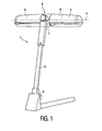
Fig. 1 is a perspective view of an embodiment of an irradiation device according to the invention, -
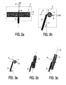
Figs. 2a and b are a schematic top view and a schematic side view, respectively, of an upper part of the irradiation device ofFigure 1 , -
Figs. 3a, b and c are schematic side views of the irradiation device ofFig. 1 when it is being moved from an operational position into a rest position, -
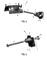
Fig. 4 is an exploded view of a blocking system of the irradiation device according to the invention, -
Fig. 5 is an exploded view of a connection system of a further embodiment of an irradiation device according to the invention, and -
Figs. 6a and 6b are a schematic view of a further irradiation device and a schematic view of an upper part of the irradiation device ofFigure 6a , respectively. -
Figure 1 shows anirradiation device 1 according to the invention, comprising abase part 2 and asupport 3 longitudinally extending from thebase part 2 at an angle α relative to a vertical axis V. It is noted that, although this embodiment of the device is a suntanning device, it may alternatively comprise other types of irradiation devices. The device furthermore comprises ahousing 4 comprising acentral axis 5, at least oneradiation unit 6, and aradiation emission plane 7. Theradiation unit 6 in this embodiment comprises compact HPA lamps, but it is noted that any known type of radiation source may be applied. Theradiation emission plane 7 is the plane through which the radiation leaves the housing during operation of the device. Thehousing 4 is pivotally connected to saidsupport 3 via apivot shaft 8. Thehousing 4 is pivotable between an operational position A (seeFigs. 2a and 3a ), in which the radiation emission plane is horizontal (X), and a rest position B, in which the radiation emission plane is vertical (Y), and thecentral axis 5 of thehousing 4 encloses the angle (α) with the vertical axis, in this embodiment extending parallel to the support (seeFigure 3c ). - As can be seen in
Figs. 2 a and b, thepivot axis 8 extends from thesupport 3 enclosing an angle (α/2) with the vertical plane Y and with the horizontal plane X. In this manner the housing can be moved from its operational position A shown inFigure 3a into its rest position B shown inFigure 3c by means of a single rotation about a single pivot axis.Figure 3b shows an in-between position of the housing between the positions A and B, which is not a static position, but a position that occurs during the fluent movement of the housing about thepivot shaft 8 from position A to B. Since the pivot shaft is arranged in the above described manner, the device according to the invention can be easily folded for storage purposes, which enhances the user-friendliness of the irradiation device, while it also provides a solid construction. -
Figure 4 is an exploded view of ablocking system 10 of anirradiation device 1 according to the invention. Theblocking system 10 is provided for releasably blocking thehousing 4 in its operational position A and in its rest position B relative to thesupport 3. In this embodiment, theblocking system 10 comprises a blockingelement 11 withprotrusions 12, which is provided coaxially with thepivot shaft 8 near an end of thepivot shaft 8 in the vicinity of its connection to thesupport 3. Achamber 13 for receiving said blockingelement 11 is provided in thehousing 4, here shown as an inner part of the housing, saidchamber 13 comprisingnotches 22 for co-operation with saidprotrusions 12. The notches receive the protrusions in dependence on the rotational movement of the housing, and thus of the chamber, relative to the pivot shaft, and thus relative to the blocking element. This construction ensures that thehousing 4 maintains the position in which it is set by the user, this position being either the operational position or the rest position. In the operational position, the blocking system prevents an unsafe situation for the user of the device, which would occur if the housing were to rotate by itself about the pivot shaft while a user is present beneath the radiation emission plane. In the rest position, the blocking system prevents damage to the housing or objects present near the device, which would occur if the housing were to rotate by itself about the pivot shaft while it is stored away. -
Figure 5 is an exploded view of aconnection system 30 of a further embodiment of an irradiation device 1' according to the invention. Theconnection system 30 is provided for connecting thepivot shaft 8 to thesupport 3 and comprises afastening element 31 for receiving theshaft 8, which element is attached to thesupport 3, and aclamp element 32 for clamping theshaft 8 in said fastening element. It is noted that other types of connection systems may alternatively be used to connect the axis to the support. For example, the connection system as shown inFigure 4 may be applied, this system comprising two housing parts which are connectable to the support and between which the shaft is clamped. - It is noted that, although the irradiation device as described in the above embodiments is a suntanning device, the irradiation device according to the invention may also be of another type. Medical irradiation devices and devices for illumination, for example, may also benefit from the advantages resulting from the invention.
- It is noted that other means may be provided for easily moving the housing between the operational position and the rest position in an irradiation device comprising a base part, a support longitudinally extending from the base part and enclosing an angle (α) with a vertical axis, and a housing comprising a central axis, at least one radiation unit, and a radiation emission plane, said housing being pivotally connected to said support via a pivot shaft so as to be pivotable between an operational position, in which the radiation emission plane is horizontal, and a rest position, in which the radiation emission plane is vertical, and the central axis of the housing encloses the angle (α) with the vertical axis.
- Said means may comprise a gear system comprising a first gear wheel provided at the connection point of the support to the lamp housing, a second gear wheel engaging the first gear wheel, connected to the lamp housing, and rotatable about the pivot shaft, the diameter of the first gear wheel being related to the diameter of the second gear wheel as follows: first gear wheel diameter = second gear wheel diameter x (90/ α). In this manner the housing can be moved by the user from the operational position into a position parallel with the support by means of only one rotational operation. This is advantageous both when the irradiation device is to be put up before use and when it is to be stored after use, and thus enhances the user-friendliness of the device.
-
Figure 6a shows an irradiation device according to the invention, comprising a base part (not shown), asupport 53 longitudinally extending from the base part and enclosing an angle (α) with a vertical axis V, ahousing 54 comprising a central axis, at least oneradiation unit 56, and a radiation emission plane 57, said housing being pivotally connected to said support via apivot shaft 58, said housing being pivotable between an operational position, in which the radiation emission plane is horizontal, and a rest position, in which the radiation emission plane is vertical, and the central axis of the housing encloses the angle (α) with the vertical axis. It is noted that, although this embodiment of the device is a suntanning device, it may also comprise other types of irradiation devices. -
Figure 6b shows an upper part of the irradiation device in more detail. Thegear system 60 comprises a first gear wheel D1 provided at the connection point of thesupport 53 to thehousing 54, and a second gear wheel D2 for co-operation with the first gear wheel D1, which is connected to the housing 54 (not shown in the Figure) and is rotatable about thepivot shaft 58. The second gear wheel D2 is fixedly fastened to the housing and can only rotate together with the housing. Thepivot shaft 58 is pivotally connected to thesupport 53 via afurther pivot shaft 68. The diameter of the first gear wheel D1 is related to the diameter of the second gear wheel D2 as follows: first gear wheel diameter D1 = second gear wheel diameter D2 x (90/ α). With this gear ratio, thehousing 54 can be moved in one rotational movement through 90° from the operational position into the rest position parallel to the support, and vice versa. In this embodiment, thegear wheels D 1 and D2 comprise conoid gear wheels, but it is noted that other known types of gear wheels may alternatively be applied.
Claims (5)
- An irradiation device (1), comprising:- a base part (2), extending in the horizontal plane (X)- a support (3), longitudinally extending from the base part (2) and enclosing an angle α>0 with vertical axis V, and- an elongated housing (4) comprising a central axis (5), at least one radiation unit (6), and a radiation emission plane (7), said housing (4) being pivotally connected to said support via a pivot axis (8),- said housing (4) being pivotable between an operational position (A), in which the radiation emission plane (7) is horizontal (X), and a rest position (B), in which the radiation emission plane (7) is vertical (Y), and the central axis (5) of the housing (4) encloses the angle α>0 with the vertical axis (V), so that the central axis (5) is parallel to the support (3)whereby the pivot axis (8) extends from the support so as to enclose an angle α/2 the horizontal plane (X) and with the vertical plane (Y).
- An irradiation device as claimed in Claim 1, characterized in that a blocking system (10) is provided for releasably blocking the housing (4) in its operational position (A) and in its rest position (B) relative to the support (3).
- An irradiation device as claimed in Claim 2, characterized in that the blocking system (10) comprises:- a cylindrical blocking element (11) with protrusions (12) which is provided coaxially with the pivot shaft (8) near an end of the pivot shaft (8) in the vicinity of its connection to the support (3),- a chamber (13) provided in the housing (4) for receiving said blocking element (11), comprising notches (22) for co-operation with said protrusions (12).
- An irradiation device as claimed in Claim 1, characterized in that a connection system (30) is provided for connecting the pivot axis (8) to the support, which system comprises:- a fastening element (31) for receiving the shaft (8), which is attachable to the support (3),- a clamp element (32) for clamping the shaft (8) in said fastening element (31).
- An irradiation device as claimed in any of the preceding Claims, characterized in that the device (1) is a suntanning device.
Priority Applications (1)
| Application Number | Priority Date | Filing Date | Title |
|---|---|---|---|
| EP04729488A EP1620180B1 (en) | 2003-04-28 | 2004-04-26 | Collapsible irradiation device |
Applications Claiming Priority (3)
| Application Number | Priority Date | Filing Date | Title |
|---|---|---|---|
| EP03101162 | 2003-04-28 | ||
| EP04729488A EP1620180B1 (en) | 2003-04-28 | 2004-04-26 | Collapsible irradiation device |
| PCT/IB2004/050510 WO2004096363A1 (en) | 2003-04-28 | 2004-04-26 | Collapsible irradiation device |
Publications (2)
| Publication Number | Publication Date |
|---|---|
| EP1620180A1 EP1620180A1 (en) | 2006-02-01 |
| EP1620180B1 true EP1620180B1 (en) | 2008-05-28 |
Family
ID=33395941
Family Applications (1)
| Application Number | Title | Priority Date | Filing Date |
|---|---|---|---|
| EP04729488A Expired - Lifetime EP1620180B1 (en) | 2003-04-28 | 2004-04-26 | Collapsible irradiation device |
Country Status (5)
| Country | Link |
|---|---|
| US (1) | US7326944B2 (en) |
| EP (1) | EP1620180B1 (en) |
| AT (1) | ATE396769T1 (en) |
| DE (1) | DE602004014128D1 (en) |
| WO (1) | WO2004096363A1 (en) |
Family Cites Families (6)
| Publication number | Priority date | Publication date | Assignee | Title |
|---|---|---|---|---|
| DE2616893A1 (en) * | 1976-04-15 | 1977-11-03 | Patra Patent Treuhand | RADIATION LAMP |
| GB2082747B (en) * | 1980-08-20 | 1983-10-26 | Hancock Michael Robin | Sun lamps |
| GB2120315B (en) * | 1982-05-06 | 1986-03-05 | Herbert Chinn | Pivotal mount and stand incorporating such a mount |
| US4624259A (en) * | 1985-01-09 | 1986-11-25 | Glenn Welt | Full body tanning apparatus |
| US5084810A (en) * | 1990-11-27 | 1992-01-28 | Soddy Huang | Structure of built-up desk lamp |
| US5339233A (en) * | 1993-05-12 | 1994-08-16 | Roger Yang | Lamp assembly |
-
2004
- 2004-04-26 EP EP04729488A patent/EP1620180B1/en not_active Expired - Lifetime
- 2004-04-26 DE DE602004014128T patent/DE602004014128D1/en not_active Expired - Lifetime
- 2004-04-26 US US10/554,228 patent/US7326944B2/en not_active Expired - Fee Related
- 2004-04-26 AT AT04729488T patent/ATE396769T1/en not_active IP Right Cessation
- 2004-04-26 WO PCT/IB2004/050510 patent/WO2004096363A1/en not_active Ceased
Also Published As
| Publication number | Publication date |
|---|---|
| ATE396769T1 (en) | 2008-06-15 |
| DE602004014128D1 (en) | 2008-07-10 |
| US7326944B2 (en) | 2008-02-05 |
| US20070023687A1 (en) | 2007-02-01 |
| WO2004096363A1 (en) | 2004-11-11 |
| EP1620180A1 (en) | 2006-02-01 |
Similar Documents
| Publication | Publication Date | Title |
|---|---|---|
| US6186459B1 (en) | Angle/direction adjustable display device | |
| CN112761975B (en) | A folding device with telescopic and storage functions and a folding fan thereof | |
| US4674722A (en) | Medical accessory pole clamp | |
| FI101125B (en) | Portable device attachment | |
| US5082222A (en) | Supporting device | |
| WO1999020935A1 (en) | Positionable flashlight and holder | |
| US5428515A (en) | Electric lighting assembly | |
| US5833195A (en) | Gas retaining device | |
| US6328271B1 (en) | Holder for a mobile telephone | |
| US7326944B2 (en) | Collapsible irradiation device | |
| US20100266104A1 (en) | X-ray stand with variable jaw size | |
| US6005254A (en) | Irradiation device | |
| JP5037287B2 (en) | Stand type lighting fixture | |
| CN110062731A (en) | For the steering unit and vehicle of vehicle, especially battery-operated motor cycle | |
| CN101070953B (en) | Orientable Lighting Device | |
| US20030211766A1 (en) | Joint arrangement for guiding a cable therethrough | |
| ES2671330T3 (en) | Bicycle fixing device | |
| US4624259A (en) | Full body tanning apparatus | |
| JP4951453B2 (en) | Stand type lighting fixture | |
| WO2001002057A3 (en) | Hose clamping device | |
| JP6920339B2 (en) | Orientable device for video / photography equipment | |
| TW202332541A (en) | Clamp with rotatable advancement apparatus | |
| JPH07134907A (en) | Stand type luminaire | |
| JPS6210484Y2 (en) | ||
| US20190293271A1 (en) | Lighting device |
Legal Events
| Date | Code | Title | Description |
|---|---|---|---|
| PUAI | Public reference made under article 153(3) epc to a published international application that has entered the european phase |
Free format text: ORIGINAL CODE: 0009012 |
|
| 17P | Request for examination filed |
Effective date: 20051128 |
|
| AK | Designated contracting states |
Kind code of ref document: A1 Designated state(s): AT BE BG CH CY CZ DE DK EE ES FI FR GB GR HU IE IT LI LU MC NL PL PT RO SE SI SK TR |
|
| DAX | Request for extension of the european patent (deleted) | ||
| GRAP | Despatch of communication of intention to grant a patent |
Free format text: ORIGINAL CODE: EPIDOSNIGR1 |
|
| GRAS | Grant fee paid |
Free format text: ORIGINAL CODE: EPIDOSNIGR3 |
|
| GRAA | (expected) grant |
Free format text: ORIGINAL CODE: 0009210 |
|
| AK | Designated contracting states |
Kind code of ref document: B1 Designated state(s): AT BE BG CH CY CZ DE DK EE ES FI FR GB GR HU IE IT LI LU MC NL PL PT RO SE SI SK TR |
|
| REG | Reference to a national code |
Ref country code: GB Ref legal event code: FG4D |
|
| REG | Reference to a national code |
Ref country code: CH Ref legal event code: EP |
|
| REF | Corresponds to: |
Ref document number: 602004014128 Country of ref document: DE Date of ref document: 20080710 Kind code of ref document: P |
|
| REG | Reference to a national code |
Ref country code: IE Ref legal event code: FG4D |
|
| PG25 | Lapsed in a contracting state [announced via postgrant information from national office to epo] |
Ref country code: SI Free format text: LAPSE BECAUSE OF FAILURE TO SUBMIT A TRANSLATION OF THE DESCRIPTION OR TO PAY THE FEE WITHIN THE PRESCRIBED TIME-LIMIT Effective date: 20080528 |
|
| PG25 | Lapsed in a contracting state [announced via postgrant information from national office to epo] |
Ref country code: FI Free format text: LAPSE BECAUSE OF FAILURE TO SUBMIT A TRANSLATION OF THE DESCRIPTION OR TO PAY THE FEE WITHIN THE PRESCRIBED TIME-LIMIT Effective date: 20080528 Ref country code: ES Free format text: LAPSE BECAUSE OF FAILURE TO SUBMIT A TRANSLATION OF THE DESCRIPTION OR TO PAY THE FEE WITHIN THE PRESCRIBED TIME-LIMIT Effective date: 20080908 |
|
| PG25 | Lapsed in a contracting state [announced via postgrant information from national office to epo] |
Ref country code: AT Free format text: LAPSE BECAUSE OF FAILURE TO SUBMIT A TRANSLATION OF THE DESCRIPTION OR TO PAY THE FEE WITHIN THE PRESCRIBED TIME-LIMIT Effective date: 20080528 Ref country code: NL Free format text: LAPSE BECAUSE OF FAILURE TO SUBMIT A TRANSLATION OF THE DESCRIPTION OR TO PAY THE FEE WITHIN THE PRESCRIBED TIME-LIMIT Effective date: 20080528 |
|
| NLV1 | Nl: lapsed or annulled due to failure to fulfill the requirements of art. 29p and 29m of the patents act | ||
| PG25 | Lapsed in a contracting state [announced via postgrant information from national office to epo] |
Ref country code: PT Free format text: LAPSE BECAUSE OF FAILURE TO SUBMIT A TRANSLATION OF THE DESCRIPTION OR TO PAY THE FEE WITHIN THE PRESCRIBED TIME-LIMIT Effective date: 20081028 Ref country code: SE Free format text: LAPSE BECAUSE OF FAILURE TO SUBMIT A TRANSLATION OF THE DESCRIPTION OR TO PAY THE FEE WITHIN THE PRESCRIBED TIME-LIMIT Effective date: 20080828 Ref country code: DK Free format text: LAPSE BECAUSE OF FAILURE TO SUBMIT A TRANSLATION OF THE DESCRIPTION OR TO PAY THE FEE WITHIN THE PRESCRIBED TIME-LIMIT Effective date: 20080528 Ref country code: CZ Free format text: LAPSE BECAUSE OF FAILURE TO SUBMIT A TRANSLATION OF THE DESCRIPTION OR TO PAY THE FEE WITHIN THE PRESCRIBED TIME-LIMIT Effective date: 20080528 |
|
| PG25 | Lapsed in a contracting state [announced via postgrant information from national office to epo] |
Ref country code: SK Free format text: LAPSE BECAUSE OF FAILURE TO SUBMIT A TRANSLATION OF THE DESCRIPTION OR TO PAY THE FEE WITHIN THE PRESCRIBED TIME-LIMIT Effective date: 20080528 Ref country code: BE Free format text: LAPSE BECAUSE OF FAILURE TO SUBMIT A TRANSLATION OF THE DESCRIPTION OR TO PAY THE FEE WITHIN THE PRESCRIBED TIME-LIMIT Effective date: 20080528 Ref country code: RO Free format text: LAPSE BECAUSE OF FAILURE TO SUBMIT A TRANSLATION OF THE DESCRIPTION OR TO PAY THE FEE WITHIN THE PRESCRIBED TIME-LIMIT Effective date: 20080528 |
|
| PLBE | No opposition filed within time limit |
Free format text: ORIGINAL CODE: 0009261 |
|
| STAA | Information on the status of an ep patent application or granted ep patent |
Free format text: STATUS: NO OPPOSITION FILED WITHIN TIME LIMIT |
|
| PG25 | Lapsed in a contracting state [announced via postgrant information from national office to epo] |
Ref country code: EE Free format text: LAPSE BECAUSE OF FAILURE TO SUBMIT A TRANSLATION OF THE DESCRIPTION OR TO PAY THE FEE WITHIN THE PRESCRIBED TIME-LIMIT Effective date: 20080528 Ref country code: BG Free format text: LAPSE BECAUSE OF FAILURE TO SUBMIT A TRANSLATION OF THE DESCRIPTION OR TO PAY THE FEE WITHIN THE PRESCRIBED TIME-LIMIT Effective date: 20080828 |
|
| 26N | No opposition filed |
Effective date: 20090303 |
|
| PG25 | Lapsed in a contracting state [announced via postgrant information from national office to epo] |
Ref country code: IT Free format text: LAPSE BECAUSE OF FAILURE TO SUBMIT A TRANSLATION OF THE DESCRIPTION OR TO PAY THE FEE WITHIN THE PRESCRIBED TIME-LIMIT Effective date: 20080528 |
|
| REG | Reference to a national code |
Ref country code: CH Ref legal event code: PL |
|
| PG25 | Lapsed in a contracting state [announced via postgrant information from national office to epo] |
Ref country code: LI Free format text: LAPSE BECAUSE OF NON-PAYMENT OF DUE FEES Effective date: 20090430 Ref country code: CH Free format text: LAPSE BECAUSE OF NON-PAYMENT OF DUE FEES Effective date: 20090430 |
|
| PG25 | Lapsed in a contracting state [announced via postgrant information from national office to epo] |
Ref country code: MC Free format text: LAPSE BECAUSE OF NON-PAYMENT OF DUE FEES Effective date: 20090430 Ref country code: IE Free format text: LAPSE BECAUSE OF NON-PAYMENT OF DUE FEES Effective date: 20090426 |
|
| PG25 | Lapsed in a contracting state [announced via postgrant information from national office to epo] |
Ref country code: PL Free format text: LAPSE BECAUSE OF FAILURE TO SUBMIT A TRANSLATION OF THE DESCRIPTION OR TO PAY THE FEE WITHIN THE PRESCRIBED TIME-LIMIT Effective date: 20080528 |
|
| PGFP | Annual fee paid to national office [announced via postgrant information from national office to epo] |
Ref country code: GB Payment date: 20100330 Year of fee payment: 7 |
|
| PGFP | Annual fee paid to national office [announced via postgrant information from national office to epo] |
Ref country code: FR Payment date: 20100507 Year of fee payment: 7 |
|
| PG25 | Lapsed in a contracting state [announced via postgrant information from national office to epo] |
Ref country code: GR Free format text: LAPSE BECAUSE OF FAILURE TO SUBMIT A TRANSLATION OF THE DESCRIPTION OR TO PAY THE FEE WITHIN THE PRESCRIBED TIME-LIMIT Effective date: 20080829 |
|
| PGFP | Annual fee paid to national office [announced via postgrant information from national office to epo] |
Ref country code: DE Payment date: 20100630 Year of fee payment: 7 |
|
| PG25 | Lapsed in a contracting state [announced via postgrant information from national office to epo] |
Ref country code: LU Free format text: LAPSE BECAUSE OF NON-PAYMENT OF DUE FEES Effective date: 20090426 |
|
| PG25 | Lapsed in a contracting state [announced via postgrant information from national office to epo] |
Ref country code: HU Free format text: LAPSE BECAUSE OF FAILURE TO SUBMIT A TRANSLATION OF THE DESCRIPTION OR TO PAY THE FEE WITHIN THE PRESCRIBED TIME-LIMIT Effective date: 20081129 |
|
| PG25 | Lapsed in a contracting state [announced via postgrant information from national office to epo] |
Ref country code: TR Free format text: LAPSE BECAUSE OF FAILURE TO SUBMIT A TRANSLATION OF THE DESCRIPTION OR TO PAY THE FEE WITHIN THE PRESCRIBED TIME-LIMIT Effective date: 20080528 |
|
| PG25 | Lapsed in a contracting state [announced via postgrant information from national office to epo] |
Ref country code: CY Free format text: LAPSE BECAUSE OF FAILURE TO SUBMIT A TRANSLATION OF THE DESCRIPTION OR TO PAY THE FEE WITHIN THE PRESCRIBED TIME-LIMIT Effective date: 20080528 |
|
| GBPC | Gb: european patent ceased through non-payment of renewal fee |
Effective date: 20110426 |
|
| REG | Reference to a national code |
Ref country code: FR Ref legal event code: ST Effective date: 20111230 |
|
| PG25 | Lapsed in a contracting state [announced via postgrant information from national office to epo] |
Ref country code: FR Free format text: LAPSE BECAUSE OF NON-PAYMENT OF DUE FEES Effective date: 20110502 Ref country code: DE Free format text: LAPSE BECAUSE OF NON-PAYMENT OF DUE FEES Effective date: 20111101 |
|
| PG25 | Lapsed in a contracting state [announced via postgrant information from national office to epo] |
Ref country code: GB Free format text: LAPSE BECAUSE OF NON-PAYMENT OF DUE FEES Effective date: 20110426 |
|
| REG | Reference to a national code |
Ref country code: DE Ref legal event code: R119 Ref document number: 602004014128 Country of ref document: DE Effective date: 20111101 |