EP1619486A2 - Non-invasive magnetostrictive sensor - Google Patents
Non-invasive magnetostrictive sensor Download PDFInfo
- Publication number
- EP1619486A2 EP1619486A2 EP05076509A EP05076509A EP1619486A2 EP 1619486 A2 EP1619486 A2 EP 1619486A2 EP 05076509 A EP05076509 A EP 05076509A EP 05076509 A EP05076509 A EP 05076509A EP 1619486 A2 EP1619486 A2 EP 1619486A2
- Authority
- EP
- European Patent Office
- Prior art keywords
- magnetostrictive
- layer
- magnetostrictive layer
- structural element
- magnetic flux
- Prior art date
- Legal status (The legal status is an assumption and is not a legal conclusion. Google has not performed a legal analysis and makes no representation as to the accuracy of the status listed.)
- Withdrawn
Links
- 230000035699 permeability Effects 0.000 claims abstract description 76
- 230000004907 flux Effects 0.000 claims abstract description 75
- 230000008859 change Effects 0.000 claims abstract description 55
- 230000035515 penetration Effects 0.000 claims description 19
- 230000004044 response Effects 0.000 claims description 19
- 239000000463 material Substances 0.000 description 19
- 238000000034 method Methods 0.000 description 15
- XEEYBQQBJWHFJM-UHFFFAOYSA-N Iron Chemical compound [Fe] XEEYBQQBJWHFJM-UHFFFAOYSA-N 0.000 description 12
- UGKDIUIOSMUOAW-UHFFFAOYSA-N iron nickel Chemical compound [Fe].[Ni] UGKDIUIOSMUOAW-UHFFFAOYSA-N 0.000 description 11
- 229910052742 iron Inorganic materials 0.000 description 6
- 230000035945 sensitivity Effects 0.000 description 6
- 229910000640 Fe alloy Inorganic materials 0.000 description 2
- PXHVJJICTQNCMI-UHFFFAOYSA-N Nickel Chemical compound [Ni] PXHVJJICTQNCMI-UHFFFAOYSA-N 0.000 description 2
- 229910000831 Steel Inorganic materials 0.000 description 2
- 230000004048 modification Effects 0.000 description 2
- 238000012986 modification Methods 0.000 description 2
- 239000010959 steel Substances 0.000 description 2
- 229910001030 Iron–nickel alloy Inorganic materials 0.000 description 1
- 230000001133 acceleration Effects 0.000 description 1
- 239000011248 coating agent Substances 0.000 description 1
- 238000000576 coating method Methods 0.000 description 1
- 239000004020 conductor Substances 0.000 description 1
- 230000007423 decrease Effects 0.000 description 1
- 230000000694 effects Effects 0.000 description 1
- 229910052759 nickel Inorganic materials 0.000 description 1
- 230000000704 physical effect Effects 0.000 description 1
- 239000007787 solid Substances 0.000 description 1
- 239000007921 spray Substances 0.000 description 1
- 238000003466 welding Methods 0.000 description 1
Images


Classifications
-
- G—PHYSICS
- G01—MEASURING; TESTING
- G01L—MEASURING FORCE, STRESS, TORQUE, WORK, MECHANICAL POWER, MECHANICAL EFFICIENCY, OR FLUID PRESSURE
- G01L3/00—Measuring torque, work, mechanical power, or mechanical efficiency, in general
- G01L3/02—Rotary-transmission dynamometers
- G01L3/04—Rotary-transmission dynamometers wherein the torque-transmitting element comprises a torsionally-flexible shaft
- G01L3/10—Rotary-transmission dynamometers wherein the torque-transmitting element comprises a torsionally-flexible shaft involving electric or magnetic means for indicating
- G01L3/101—Rotary-transmission dynamometers wherein the torque-transmitting element comprises a torsionally-flexible shaft involving electric or magnetic means for indicating involving magnetic or electromagnetic means
- G01L3/102—Rotary-transmission dynamometers wherein the torque-transmitting element comprises a torsionally-flexible shaft involving electric or magnetic means for indicating involving magnetic or electromagnetic means involving magnetostrictive means
-
- G—PHYSICS
- G01—MEASURING; TESTING
- G01L—MEASURING FORCE, STRESS, TORQUE, WORK, MECHANICAL POWER, MECHANICAL EFFICIENCY, OR FLUID PRESSURE
- G01L1/00—Measuring force or stress, in general
- G01L1/12—Measuring force or stress, in general by measuring variations in the magnetic properties of materials resulting from the application of stress
- G01L1/125—Measuring force or stress, in general by measuring variations in the magnetic properties of materials resulting from the application of stress by using magnetostrictive means
-
- G—PHYSICS
- G01—MEASURING; TESTING
- G01L—MEASURING FORCE, STRESS, TORQUE, WORK, MECHANICAL POWER, MECHANICAL EFFICIENCY, OR FLUID PRESSURE
- G01L1/00—Measuring force or stress, in general
- G01L1/12—Measuring force or stress, in general by measuring variations in the magnetic properties of materials resulting from the application of stress
- G01L1/127—Measuring force or stress, in general by measuring variations in the magnetic properties of materials resulting from the application of stress by using inductive means
-
- G—PHYSICS
- G01—MEASURING; TESTING
- G01L—MEASURING FORCE, STRESS, TORQUE, WORK, MECHANICAL POWER, MECHANICAL EFFICIENCY, OR FLUID PRESSURE
- G01L3/00—Measuring torque, work, mechanical power, or mechanical efficiency, in general
- G01L3/02—Rotary-transmission dynamometers
- G01L3/04—Rotary-transmission dynamometers wherein the torque-transmitting element comprises a torsionally-flexible shaft
- G01L3/10—Rotary-transmission dynamometers wherein the torque-transmitting element comprises a torsionally-flexible shaft involving electric or magnetic means for indicating
- G01L3/101—Rotary-transmission dynamometers wherein the torque-transmitting element comprises a torsionally-flexible shaft involving electric or magnetic means for indicating involving magnetic or electromagnetic means
- G01L3/105—Rotary-transmission dynamometers wherein the torque-transmitting element comprises a torsionally-flexible shaft involving electric or magnetic means for indicating involving magnetic or electromagnetic means involving inductive means
Definitions
- the present invention relates to magnetostriction-based force and torque sensors and, more particularly, to a non-invasive magnetostrictive sensor used to determine force and torque due to magnetostriction of magnetostrictive materials.
- magnetostrictive materials are known in the art to be magnetostrictive by which their magnetic permeability varies with stress applied thereto, known as magnetostrictive materials.
- the physical effect is known as the "Villari" effect.
- Magnetostrictive sensor 100 of Figure 1 A consists of magnetostrictive cylindrical rod 102 of radius R and length L wrapped with a coil 104 to which a time varying current is of a specified frequency is applied.
- Magnetostrictive sensor 100 is invasively embedded within a structural element 112 (shown in phantom in Figure 1B) to determine the force applied to the structural element.
- a force applied to the structural element imposes a stress and force 106 upon the invasively embedded magnetostrictive cylindrical rod 102, thereby varying the magnetic permeability of the magnetostrictive cylindrical rod.
- the varying magnetic permeability of the invasively embedded magnetostrictive cylindrical rod 102 produces a change in the inductance and impedance of magnetostrictive sensor 100, which can be captured as a change in the voltage V S across the coil 104.
- the stress or force 106 applied to the structural element and, thus, upon magnetostrictive sensor 100 can be determined by the produced change in inductance or impedance via the change in the voltage V s by techniques well known in the art.
- Magnetostrictive materials such as nickel and nickel-iron alloys, are typically conductive. Therefore, the frequency of the time varying current is, typically in the kHz range to enhance bandwidth and response, in conjunction with the conductivity of magnetostrictive cylindrical rod 102, results in eddy currents near the surface 108 of the magnetostrictive cylindrical rod by which the magnetic flux produced by the coil 104 is predominantly confined within the skin depth 110, depicted in Figure 1B, of the surface. Therefore, magnetostrictive sensor 100 only responds to stress and force 106 near the surface 108 of magnetostrictive cylindrical rod 102.
- Equation 1 is exact for a planar geometry, and approximate, but sufficiently close for design purposes, for other geometries such as the cylindrical case shown in Figure 1.
- the skin depths of materials and the correlation of magnetic flux depth penetration to eddy currents and skin depth, are well known in the art.
- the present invention is a magnetostrictive sensor to sense force or torque (stress) applied to a structural element resulting in strain in the structural element to which the magnetostrictive sensor is non-invasively attached by an intimate contact with the structural element, whereby no air gap is present at the contact interface between the magnetostrictive sensor and the structural element.
- the magnetostrictive sensor according to the present invention consists of, at least, a magnetostrictive layer, wherein the term "layer” is meant to include a "layer”, in intimate contact with a source of magnetic flux, whereby no air gap or an air gap as small as possible is present at the contact interface between the magnetostrictive layer and the source of magnetic flux, and wherein the source of magnetic flux is constructed to effectively and efficiently guide the produced magnetic flux to the magnetostrictive layer in order to maximize the magnetostrictive sensor response to strain.
- the air gap between the source of magnetic flux and the magnetostrictive layer should be as small as possible and is therefore preferably of zero length (no air gap).
- the non-invasive, fixed, intimate contact attachment of the magnetostrictive layer to the structural element can be accomplished by using kinetic spray, magnetic pulse welding of a sheet of magnetostrictive material to the structural element, or other techniques well known in the art, whereby no air gap is present at the contact interface between the magnetostrictive sensor and the structural element.
- the source of magnetic flux is, preferably, a coil (or coils), to which a, preferably, sinusoidally alternating current is applied to produce a magnetic flux, mounted within a core, whereby the core has a magnetic permeability selected to guide the magnetic flux generated by the current carrying coil within the core to the magnetostrictive layer in order to maximize the magnetostrictive sensor response to strain, and whereby no air gap or an air gap as small as possible is present at the contact interface between the magnetostrictive layer and the source of magnetic flux.
- a coil or coils
- a force or torque applied to the structural element to which the magnetostrictive sensor is attached produces a stress within the structural element which is transferred to the magnetostrictive layer of the magnetostrictive sensor due to its fixed, intimate contact with the structural element, thereby varying the magnetic permeability of the magnetostrictive layer.
- the varying magnetic permeability of the magnetostrictive layer produces a change in the magnetic flux, thereby producing a change in the inductance and impedance of the coil of the magnetostrictive sensor, and thereby producing a change in the voltage across the coil.
- the force or torque applied to the structural element and, thus, upon the magnetostrictive sensor can be determined by the produced change in inductance or impedance via the change in the voltage of the coil by techniques well known in the art.
- the structural element material can be chosen to a large degree independently of the magnetostrictive sensor. For instance, if large stress levels are expected, a material with high yield strength such as steel can be chosen for the structural element, and the magnetostrictive layer can be chosen primarily for its magnetostrictive qualities, such as large permeability change versus stress.
- Figures 2A through 2E depict a first preferred embodiment of a non-invasive magnetostrictive sensor 200 according to the present invention to sense force or torque 212 applied to a structural element 204, which may be made of a conducting, or of a non-conducting, material.
- the magnetostrictive sensor 200 is non-invasively attached to plane surface 202 of the structural element to thereby provide an intimate contact with the structural element, whereby no air gap is present at the plane of contact interface 214 between the magnetostrictive sensor and the structural element.
- Non-invasive magnetostrictive sensor 200 consists of magnetostrictive layer (by the term “layer” is also meant “coating") 210 of thickness 216 in intimate contact with a source of magnetic flux 220, whereby no air gap or as small of an air gap as possible is present at the contact interface 222 between the magnetostrictive layer and the source of magnetic flux.
- the source of magnetic flux 220 is constructed to effectively and efficiently guide the produced magnetic flux 224, depicted by way of example in Figure 2B, to the magnetostrictive layer 210 in order to maximize the magnetostrictive sensor response to strain.
- Figure 2B depicts an example of a source of magnetic flux 220 which is, preferably, a typical conventional coil 206 mounted inside a core structure 208, preferably having a predetermined number N of turns wound around a center core member 218 occupying space 226 of the core structure, whose magnetic characteristics and operation are well known in the art.
- the core structure 208 will be preferably designed to orient the flux lines according to the direction of the strain, in order to maximize sensitivity. A parallelepiped shape may be desirable in that respect.
- An alternating current preferably, sinusoidally alternating current, is applied to the coil to produce a time varying magnetic flux 224 within the core structure 208.
- the core structure 208 has a high magnetic permeability selected to guide the magnetic flux generated by the alternating current carrying coil 206 within the cylindrical core structure to the magnetostrictive layer 210 in order to maximize the magnetostrictive sensor response to strain.
- Force or torque 212 is applied to the structural element 204 to which the magnetostrictive sensor 200 is fixedly attached, and thereby produces a stress within the structural element which is transferred to the magnetostrictive layer 210 of the magnetostrictive sensor due to its fixed, intimate contact with the structural element, and thereby varies the magnetic permeability of the magnetostrictive layer.
- the varying magnetic permeability of the magnetostrictive layer 210 produces a change in the magnetic flux 224, thereby producing a change in the inductance and impedance of the coil 206 of magnetostrictive sensor 200, and thereby producing a change in the voltage V' s across the coil.
- Force 212 applied to structural element 204 and, thus, upon magnetostrictive sensor 200 can be determined by the produced change in inductance or impedance of the coil 206 via the change in the voltage V' S of the coil by techniques well known in the art.
- Figure 2C depicts a top view of a first preferred embodiment of a non-invasive magnetostrictive sensor 200 according to the present invention utilizing the source of magnetic flux 220 as shown in Figure 2B.
- the depth of penetration 228 of the magnetic flux 224 into the magnetostrictive layer 210 is a function of the thickness of the layer 216 with respect to the frequency of the, preferably, sinusoidal alternating current supplied to coil 206, the magnetic permeability ⁇ C of the magnetostrictive layer, the magnetic permeability ⁇ S of the structural element 204, the conductivity ⁇ C of the magnetostrictive layer, and the conductivity ⁇ S of the structural element, and can be referenced to the skin depth, as defined by equation (1), of the magnetostrictive layer and/or the skin depth of the structural element.
- ⁇ C is the magnetic permeability of the magnetostrictive layer
- ⁇ C is the conductivity of the magnetostrictive layer
- f is the frequency of the current supplied to coil 206.
- ⁇ S is the magnetic permeability of the structural element
- ⁇ S is the conductivity of the structural element
- f is the frequency of the current supplied to coil 206.
- the frequency of the alternating current supplied to coil 206, the magnetic permeability ⁇ C of the magnetostrictive layer 210, and the conductivity ⁇ C of the magnetostrictive layer are such that the thickness 216 of the magnetostrictive layer is greater than the skin depth ⁇ C of the magnetostrictive layer.
- magnetic flux 224 is within magnetostrictive layer 210 having a depth of penetration 228 into the magnetostrictive layer less than the thickness 216 of the magnetostrictive layer.
- the reactive part of the voltage of the coil 206 which varies in response to the magnetostriction in layer 210 can be shown to be a function of the square root of the product of the frequency of the current supplied to the coil and the magnetic permeability ⁇ C of the magnetostrictive layer 210.
- Force 212 applied to structural element 204 and, thus, upon the magnetostrictive sensor 200 can be determined by the produced change in inductance or impedance of the coil 206 via the change in the voltage V' s of the coil by techniques well known in the art.
- the frequency of the current supplied to coil 206, the magnetic permeability ⁇ C of the magnetostrictive layer 210, and the conductivity ⁇ C of the magnetostrictive layer are such that the thickness 216 of the magnetostrictive layer is approximately equal to or less than the skin depth ⁇ C of the magnetostrictive layer and the product of the magnetic permeability ⁇ S of the structural element 204 and the conductivity of the structural element ⁇ S is greater than a magnitude of at least ten times the product of the magnetic permeability ⁇ C of the magnetostrictive layer and the conductivity ⁇ C of the magnetostrictive layer.
- magnetic flux 224 is confined within the thickness 216 of magnetostrictive layer 210 and the depth of penetration 228 of the magnetic flux into the magnetostrictive layer is approximately equal to the thickness of the magnetostrictive layer, serving to increase the sensitivity of the magnetostrictive sensor 200.
- the material of the magnetostrictive layer 210 is a suitable nickel-iron alloy having a thickness 216 of 0.4 millimeters and the material of the structural element 204 is iron, the magnetic permeabilities and conductivities of both materials being well known in the art.
- the skin depth of the nickel-iron magnetostrictive layer 210 is 0.44 millimeters.
- the magnetic permeability of the stressed nickel-iron magnetostrictive layer 210 decreases resulting in an increase in the skin depth of the stressed nickel-iron magnetostrictive layer, whereas the skin depth of the stressed iron structural element 204 does not change, or changes negligibly compared to the nickel-iron layer.
- Iron is magnetostrictive, but it is much less so, by orders of magnitude, than suitable nickel-iron alloys.
- the much smaller skin depth of the stressed iron structural element 204 serves to confine the depth of penetration 228 of the magnetic flux 224 within the thickness 216 of the nickel-iron magnetostrictive layer 210 and is approximately equal to the thickness of the nickel-iron magnetostrictive layer of 0.4 millimeters.
- a thickness 216 of 0.4 millimeters of a nickel-iron magnetostrictive layer 210 applied to an iron structural element at a frequency of 1 kHz supplied to coil 206 results in a depth of penetration 228 of the magnetic flux 224 approximately equal to the thickness of the nickel-iron magnetostrictive layer.
- the reactive part of the voltage V' S of the coil 206 which varies in response to the magnetostriction in layer 210 can be shown to be a function of the product of the frequency of the current supplied to the coil and the magnetic permeability ⁇ C of the magnetostrictive layer 210.
- Force 212 applied to structural element 204 and, thus, upon magnetostrictive sensor 200 can be determined by the produced change in inductance or impedance of the coil 206 via the change in the voltage V' S of the coil by techniques well known in the art.
- the frequency of the current supplied to coil 206, the magnetic permeability ⁇ C of the magnetostrictive layer 210, and the conductivity ⁇ C of the magnetostrictive layer are such that the thickness 216 of the magnetostrictive layer is less than the skin depth ⁇ C of the magnetostrictive layer and the product of the magnetic permeability ⁇ S of the structural element 204 and the conductivity of the structural element ⁇ S is not greater than a magnitude of at least about ten times the product of the magnetic permeability ⁇ C of the magnetostrictive layer and the conductivity ⁇ C of the magnetostrictive layer.
- the depth of penetration 228 of the magnetic flux 224 exceeds the thickness 216 of the magnetostrictive layer 210 and extends into the structural element 204, whereby the magnetostrictive sensor 200 has a reduced sensitivity with respect to the second aspect of the first preferred embodiment of the present invention.
- the reactive part of the voltage V' S of the coil 206 which varies in response to the magnetostriction in layer 210 can be shown to be a function of the product of the frequency of the current supplied to the coil and the magnetic permeability ⁇ C of the magnetostrictive layer 210.
- Force 212 applied to structural element 204 and, thus, upon magnetostrictive sensor 200 can be determined by the produced change in inductance or impedance of the coil 206 via the change in the voltage V' s of the coil by techniques well known in the art.
- Figures 3A through 3D depict a second preferred embodiment of a non-invasive magnetostrictive sensor 300 according to the present invention to sense forces 302, 304 and torque 306 applied to structural element 308, in the form of a shaft or rod comprised of a material which may or may not be a conductor, to which the magnetostrictive sensor is non-invasively attached to the cylindrical surface 310 thereof to thereby provide fixed, intimate contact with the structural element, whereby no air gap is present at the contact interface 312 between the magnetostrictive sensor 300 and the structural element 308.
- the structural element 308 is depicted as being hollow with thickness 314, but the structural element may be alternatively solid.
- the non-invasive magnetostrictive sensor 300 consists of magnetostrictive layer 316 of thickness 318 in intimate contact with a source of magnetic flux 320, whereby no air gap or as small of an air gap as possible is present at the contact interface 322 between the magnetostrictive layer and the source of magnetic flux, wherein the source of magnetic flux is constructed to effectively and efficiently guide the produced magnetic flux 324 to the magnetostrictive layer 316 in order to maximize the response of the magnetostrictive sensor 300 to strain.
- the source of magnetic flux 320 is, preferably, a coil 326 mounted inside a cylindrical core structure 328 encircling the cylindrical surface 310 of the shaft or rod 308, preferably having a predetermined number N' of turns wound around the cylindrical surface of the shaft or rod, wherein the magnetic characteristics and operation thereof are well known in the art.
- An alternating current preferably, a sinusoidally alternating current is applied to the coil 326 to produce a time varying magnetic flux 324 within the cylindrical core structure, whereby the cylindrical core structure has, as described hereinabove with respect to the first preferred embodiment, a high magnetic permeability selected to guide the magnetic flux generated by the current carrying coil within the cylindrical core structure to the magnetostrictive layer 316 in order to maximize the magnetostrictive sensor response to strain.
- Force 302, 304 or torque 306 applied to structural element 308 to which the magnetostrictive sensor 300 is attached produces a stress within the structural element which is transferred to the magnetostrictive layer 316 of the magnetostrictive sensor due to its fixed, intimate contact with the structural element, thereby varying the magnetic permeability of the magnetostrictive layer.
- the varying magnetic permeability of the magnetostrictive layer 316 produces a change in the magnetic flux 324, thereby producing a change in the inductance and impedance of the coil 326 of magnetostrictive sensor 300, which can be captured as a change in the voltage across the coil (analogous to V' S as depicted in the first preferred embodiment).
- Force 302, 304 or torque 306 applied to structural element 308 and, thus, upon magnetostrictive sensor 300 can be determined by the produced change in inductance or impedance of the coil 326 via the change in the voltage of the coil by techniques well known in the art.
- Figure 3B depicts a side view of the second preferred embodiment of a non-invasive magnetostrictive sensor 300 according to the present invention as shown in Figure 3A.
- the depth of penetration 332 of the magnetic flux 324 into the magnetostrictive layer 316 is a function of the thickness of the layer 318 with respect to the frequency of the, preferably, sinusoidal current supplied to coil 326, the magnetic permeability ⁇ CC of the magnetostrictive layer, the magnetic permeability ⁇ SH of the structural element 308, the conductivity ⁇ CC of the magnetostrictive layer, and the conductivity ⁇ SH of the structural element and can be referenced to the skin depth, given by equation (1), of the magnetostrictive layer and/or the skin depth of the structural element.
- ⁇ CC is the magnetic permeability of the magnetostrictive layer
- ⁇ CC is the conductivity of the magnetostrictive layer
- f is the frequency of the current supplied to coil 326.
- ⁇ SH is the magnetic permeability of the structural element
- ⁇ SH is the conductivity of the structural element
- f is the frequency of the current supplied to coil 326.
- the frequency of the current supplied to coil 326, the magnetic permeability ⁇ CC of the magnetostrictive layer 316, and the conductivity ⁇ CC of the magnetostrictive layer are such that the thickness 318 of the magnetostrictive layer is greater than the skin depth ⁇ CC of the magnetostrictive layer.
- magnetic flux 324 is within magnetostrictive layer 316 having a depth of penetration 332 into the magnetostrictive layer 316 less than the thickness 318 of the magnetostrictive layer.
- the reactive part of the voltage of the coil 206 which varies in response to the magnetostriction in layer 210 can be shown to be a function of the square root of the product of the frequency of the current supplied to the coil and the magnetic permeability ⁇ CC of the magnetostrictive layer 316.
- Force 302, 304 and torque 306 applied to structural element 308 and, thus, upon magnetostrictive sensor 300 can be determined by the produced change in inductance or impedance of the coil 326 via the change in the voltage of the coil by techniques well known in the art.
- the frequency of the current supplied to coil 326, the magnetic permeability ⁇ CC of the magnetostrictive layer 316, and the conductivity ⁇ CC of the magnetostrictive layer are such that the thickness 318 of the magnetostrictive layer is approximately equal to or is less than the skin depth ⁇ CC of the magnetostrictive layer and the product of the magnetic permeability ⁇ SH of the structural element 308 and the conductivity of the structural element ⁇ SH is greater than a magnitude of at least about ten times the product of the magnetic permeability ⁇ CC of the magnetostrictive layer and the conductivity ⁇ CC of the magnetostrictive layer.
- magnetic flux 324 is confined within the thickness 318 of magnetostrictive layer 316 and the depth of penetration 332 of the magnetic flux into the magnetostrictive layer is approximately equal to the thickness of the magnetostrictive layer serving to increase the sensitivity of the magnetostrictive sensor 300.
- the reactive part of the voltage of the coil 326 which varies in response to the magnetostriction in layer 316 can be shown to be a function of the product of the frequency of the current supplied to the coil and the magnetic permeability ⁇ CC of the magnetostrictive layer 316.
- Force 302, 304 and torque 306 applied to structural element 308 and, thus, upon magnetostrictive sensor 300 can be determined by the produced change in inductance or impedance of the coil 326 via the change in the voltage of the coil by techniques well known in the art.
- the frequency of the current supplied to coil 326, the magnetic permeability ⁇ CC of the magnetostrictive layer 316, and the conductivity ⁇ CC of the magnetostrictive layer are such that the thickness 318 of the magnetostrictive layer is less than the skin depth ⁇ CC of the magnetostrictive layer and the product of the magnetic permeability ⁇ SH of the structural element 308 and the conductivity of the structural element ⁇ SH is not greater than a magnitude of at least about ten times the product of the magnetic permeability ⁇ CC of the magnetostrictive layer and the conductivity ⁇ CC of the magnetostrictive layer.
- the depth of penetration 332 of the magnetic flux 324 exceeds the thickness 318 of the magnetostrictive layer 316 and extends into the structural element 308, whereby the magnetostrictive sensor 300 has a reduced sensitivity with respect to the second aspect of the second preferred embodiment of the present invention.
- the reactive part of the voltage of the coil 326 which varies in response to the magnetostriction in layer 316 can be shown to be a function of the product of the frequency of the current supplied to the coil and the magnetic permeability ⁇ CC of the magnetostrictive layer 316.
- Force 302, 304, and torque 306 applied to structural element 308 and, thus, upon magnetostrictive sensor 300 can be determined by the produced change in inductance or impedance of the coil 326 via the change in the voltage of the coil by techniques well known in the art.
- Figure 4 depicts a third preferred embodiment of a non-invasive magnetostrictive sensor 400 according to the present invention to sense force or torque 212 applied to structural element 204 to which the magnetostrictive sensor is non-invasively attached to a surface 202 (for example, planar or cylindrical) of the structural element thereby providing fixed, intimate contact with the structural element, whereby no air gap is present at the contact interface 414 between the magnetostrictive sensor and the structural element.
- a surface 202 for example, planar or cylindrical
- the non-invasive magnetostrictive sensor 400 consists of magnetostrictive sensor 200 or 300 depicted in Figures 2A through 3D in fixed intimate contact with a conductive layer 410 of thickness 416, whereby no air gap is present at the contact interface 420 between the magnetostrictive layer 210 and the conductive layer.
- a magnetostrictive sensor 200 having a source of magnetic flux 220 and coil 206, is depicted in Figure 4, wherein no air gap or as small of an air gap as possible is present at the contact interface 222 between the magnetostrictive layer and the source of magnetic flux.
- the operation of magnetostrictive sensor 400 utilizing magnetostrictive sensor 300 would be analogous to that described hereinabove.
- a force 212 applied to structural element 204 to which the magnetostrictive sensor 400 is attached produces a stress within the structural element which is transferred to magnetostrictive layer 210 of the magnetostrictive sensor, via the conductive layer 410, due to its fixed intimate contact with the conductive layer, thereby varying the magnetic permeability of the magnetostrictive layer.
- the varying magnetic permeability of the magnetostrictive layer 210 produces a change in the magnetic flux 224, thereby producing a change in the inductance and impedance of the coil 206 of magnetostrictive sensor 200, and thereby producing a change in the voltage V" S across the coil.
- Force 212 applied to structural element 204 and, thus, upon magnetostrictive sensor 400 can be determined by the produced change in inductance or impedance of the coil 206 via the change in the voltage V" S of the coil by techniques well known in the art.
- the depth of penetration of the magnetic flux 224 into the magnetostrictive layer 210 is a function of the thickness of the layer 216 with respect to the frequency of the, preferably, sinusoidally alternating current supplied to coil 206, the magnetic permeability ⁇ C of the magnetostrictive layer, the magnetic permeability ⁇ CN of the conductive layer 410, the conductivity ⁇ C of the magnetostrictive layer, and the conductivity ⁇ CN of the conductive layer and can be referenced to the skin depth, given by equation (1), of the magnetostrictive layer and/or the skin depth of the conductive layer.
- the skin depth ⁇ C of the magnetostrictive layer 210 is given by equation (2), where now ⁇ C is the magnetic permeability of the magnetostrictive layer, ⁇ C is the conductivity of the magnetostrictive layer, and f is the frequency of the current supplied to coil 206.
- ⁇ CN is the magnetic permeability of the conductive layer
- ⁇ CN is the conductivity of the conductive layer
- f is the frequency of the current supplied to coil 206.
- the frequency of the current supplied to coil 206, the magnetic permeability ⁇ C of the magnetostrictive layer 210, and the conductivity ⁇ C of the magnetostrictive layer are such that the thickness 216 of the magnetostrictive layer is less than the skin depth ⁇ C of the magnetostrictive layer
- the frequency of the alternating current supplied to coil, the magnetic permeability ⁇ CN of the conductive layer 410, and the conductivity ⁇ CN of the conductive layer are such that the thickness 416 of the conductive layer is approximately equal to or larger than the skin depth ⁇ CN of the conductive layer and the product of the magnetic permeability ⁇ CN of the conductive layer and the conductivity ⁇ CN of the conductive layer is greater than a magnitude of at least about ten times the product of the magnetic permeability ⁇ C of the magnetostrictive layer and the conductivity ⁇ C of the magnetostrictive layer.
- magnetic flux 224 is confined within the thickness 216 of magnetostrictive layer 210 and the depth of penetration of the magnetic flux into the magnetostrictive layer is approximately equal to the thickness of the magnetostrictive layer serving to increase the sensitivity of the magnetostrictive sensor 400.
- the reactive part of the voltage V" S of the coil 206 which varies in response to the magnetostriction in layer 210 can be shown to be a function of the product of the frequency of the current supplied to the coil and the magnetic permeability ⁇ C of the magnetostrictive layer 210.
- Force 212 applied to structural element 204 and, thus, upon magnetostrictive sensor 200 can be determined by the produced change in inductance or impedance of the coil 206 via the change in the voltage V" S of the coil by techniques well known in the art.
- the structural element material can be chosen to a large degree independently of the magnetostrictive sensor. For instance, if large stress levels are expected, a material with high yield strength such as steel can be chosen for the structural element, and the magnetostrictive layer can be chosen primarily for its magnetostrictive qualities, such as large permeability change versus stress.
- forces 212, 302, and 304 and torque 306 applied to structural elements 204, 308 impose stresses upon the structural elements and, in particular, surface stresses upon the structural elements.
- the surface stresses imposed upon the surfaces 202, 310 of the structural elements 204, 308 in Figures 2A-2E and 3A-3C result in surface strains upon the structural elements which are transferred to the magnetostrictive layers 210, 316 due to their fixed, intimate contact with the structural elements, thereby varying the magnetic permeabilities of the magnetostrictive layers by which the forces and torque applied to the structural elements can be determined as previously described.
- the surface stress imposed upon the surface 202 of the structural element 204 in Figure 4 results in a surface strain upon the conductive layer 420 which is transferred to the magnetostrictive layer 210 due to its fixed, intimate contact with the conductive layer, thereby varying the magnetic permeability of the magnetostrictive layer by which the forces and torque applied to the structural element can be determined as previously described.
- the present invention is, in this sense, a magnetostrictive sensor to sense strain imposed upon a structural element as previously described.
- force and torque are applicable to, and inclusive of, all causes of stress, including for example pressure, vacuum, impact, acceleration, deceleration, and are, as such, within the scope of the present invention.
Landscapes
- Physics & Mathematics (AREA)
- General Physics & Mathematics (AREA)
- Electromagnetism (AREA)
- Measuring Fluid Pressure (AREA)
Abstract
A magnetostrictive sensor (200) to sense force (212) or torque applied to a structural element (204) to which the magnetostrictive sensor is non-invasively attached by a fixed, intimate contact therewith. The sensor consists of a magnetostrictive layer (210) in intimate contact with a coil (206) excited source of magnetic flux. A force or torque applied to the structural element produces a stress transferred to the magnetostrictive layer, thereby varying the magnetic permeability of the magnetostrictive layer. The change in the magnetic flux (224) produces a change in the inductance and impedance of the coil, and thereby a detectable change in the voltage V' s across the coil.
Description
- The present invention relates to magnetostriction-based force and torque sensors and, more particularly, to a non-invasive magnetostrictive sensor used to determine force and torque due to magnetostriction of magnetostrictive materials.
- Various materials are known in the art to be magnetostrictive by which their magnetic permeability varies with stress applied thereto, known as magnetostrictive materials. The physical effect is known as the "Villari" effect.
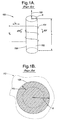
- An example of a prior art method of determining the force acting upon a magnetostrictive material subjected to stress is depicted in Figure 1A.
Magnetostrictive sensor 100 of Figure 1 A consists of magnetostrictivecylindrical rod 102 of radius R and length L wrapped with acoil 104 to which a time varying current is of a specified frequency is applied.Magnetostrictive sensor 100 is invasively embedded within a structural element 112 (shown in phantom in Figure 1B) to determine the force applied to the structural element. A force applied to the structural element imposes a stress andforce 106 upon the invasively embedded magnetostrictivecylindrical rod 102, thereby varying the magnetic permeability of the magnetostrictive cylindrical rod. The varying magnetic permeability of the invasively embedded magnetostrictivecylindrical rod 102 produces a change in the inductance and impedance ofmagnetostrictive sensor 100, which can be captured as a change in the voltage VS across thecoil 104. The stress orforce 106 applied to the structural element and, thus, uponmagnetostrictive sensor 100, can be determined by the produced change in inductance or impedance via the change in the voltage Vs by techniques well known in the art. - Magnetostrictive materials, such as nickel and nickel-iron alloys, are typically conductive. Therefore, the frequency of the time varying current is, typically in the kHz range to enhance bandwidth and response, in conjunction with the conductivity of magnetostrictive
cylindrical rod 102, results in eddy currents near thesurface 108 of the magnetostrictive cylindrical rod by which the magnetic flux produced by thecoil 104 is predominantly confined within theskin depth 110, depicted in Figure 1B, of the surface. Therefore,magnetostrictive sensor 100 only responds to stress andforce 106 near thesurface 108 of magnetostrictivecylindrical rod 102. Under planar conditions, the skin depth of a material, symbolized by δ, is known to follow:
Theskin depth 110 of magnetostrictivecylindrical rod 102 in the example of Figures 1A and 1B is defined through equation (1) where f is the frequency of the time varying current iS, µ is the magnetic permeability of the magnetostrictive cylindrical rod, and σ is the conductivity of the magnetostrictive cylindrical rod.Equation 1 is exact for a planar geometry, and approximate, but sufficiently close for design purposes, for other geometries such as the cylindrical case shown in Figure 1. The skin depths of materials and the correlation of magnetic flux depth penetration to eddy currents and skin depth, are well known in the art. - What is needed is a simpler, cost effective method for determining force and torque acting upon structural elements utilizing magnetostrictive sensors which need not be invasively embedded within the structural element.
- The present invention is a magnetostrictive sensor to sense force or torque (stress) applied to a structural element resulting in strain in the structural element to which the magnetostrictive sensor is non-invasively attached by an intimate contact with the structural element, whereby no air gap is present at the contact interface between the magnetostrictive sensor and the structural element.
- The magnetostrictive sensor according to the present invention consists of, at least, a magnetostrictive layer, wherein the term "layer" is meant to include a "layer", in intimate contact with a source of magnetic flux, whereby no air gap or an air gap as small as possible is present at the contact interface between the magnetostrictive layer and the source of magnetic flux, and wherein the source of magnetic flux is constructed to effectively and efficiently guide the produced magnetic flux to the magnetostrictive layer in order to maximize the magnetostrictive sensor response to strain. The air gap between the source of magnetic flux and the magnetostrictive layer should be as small as possible and is therefore preferably of zero length (no air gap). However, it must be recognized that under some circumstances there must be a clearance between the two, as for instance when the structural element and the magnetostrictive layer attached thereto are moving or rotating, and the source of magnetic flux is stationary. In the latter case, the reluctance of this air gap must be minimized, by reducing the length of the gap, or increasing its cross-section, in ways known in the art.
- The non-invasive, fixed, intimate contact attachment of the magnetostrictive layer to the structural element can be accomplished by using kinetic spray, magnetic pulse welding of a sheet of magnetostrictive material to the structural element, or other techniques well known in the art, whereby no air gap is present at the contact interface between the magnetostrictive sensor and the structural element. The source of magnetic flux is, preferably, a coil (or coils), to which a, preferably, sinusoidally alternating current is applied to produce a magnetic flux, mounted within a core, whereby the core has a magnetic permeability selected to guide the magnetic flux generated by the current carrying coil within the core to the magnetostrictive layer in order to maximize the magnetostrictive sensor response to strain, and whereby no air gap or an air gap as small as possible is present at the contact interface between the magnetostrictive layer and the source of magnetic flux.
- A force or torque applied to the structural element to which the magnetostrictive sensor is attached produces a stress within the structural element which is transferred to the magnetostrictive layer of the magnetostrictive sensor due to its fixed, intimate contact with the structural element, thereby varying the magnetic permeability of the magnetostrictive layer. The varying magnetic permeability of the magnetostrictive layer produces a change in the magnetic flux, thereby producing a change in the inductance and impedance of the coil of the magnetostrictive sensor, and thereby producing a change in the voltage across the coil. The force or torque applied to the structural element and, thus, upon the magnetostrictive sensor can be determined by the produced change in inductance or impedance via the change in the voltage of the coil by techniques well known in the art.
- The non-invasiveness of the proposed sensor can be further appreciated by considering that with the present invention, the structural element material can be chosen to a large degree independently of the magnetostrictive sensor. For instance, if large stress levels are expected, a material with high yield strength such as steel can be chosen for the structural element, and the magnetostrictive layer can be chosen primarily for its magnetostrictive qualities, such as large permeability change versus stress.
- Many variations in the embodiments of the present invention are contemplated as described herein in more detail. Other applications of the present invention will become apparent to those skilled in the art when the following description of the best mode contemplated for practicing the invention is read in conjunction with the accompanying drawings.
- The description herein makes reference to the accompanying drawings wherein like reference numerals refer to like parts throughout the several views.
- Figure 1A depicts a prior art magnetostrictive sensor.
- Figure 1B is a representation of the skin depth associated with the prior art magnetostrictive sensor, seen along line 1B-1B of Figure 1A.
- Figure 2A depicts a sectional side view of a first preferred embodiment of a non-invasive magnetostrictive sensor according to the present invention.
- Figure 2B depicts an example of a preferable source of magnetic flux of the first preferred embodiment of a non-invasive magnetostrictive sensor according to the present invention presented in Figure 2A.
- Figure 2C depicts a top plan view of the first preferred embodiment of a non-invasive magnetostrictive sensor according to the present invention utilizing the source of magnetic flux example presented in Figure 2B.
- Figures 2D and 2E are views similar to Figure 2B, showing other aspects of the first embodiment, wherein the magnetic flux penetration is differing.
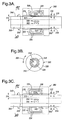
- Figure 3A depicts a sectional side view of a second preferred embodiment of a non-invasive magnetostrictive sensor according to the present invention.
- Figure 3B depicts a sectional end view of the second preferred embodiment of a non-invasive magnetostrictive sensor according to the present invention seen along
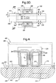
line 3B-3B of Figure 3A. - Figures 3C and 3D are views similar to Figure 3A, showing other aspects of the second embodiment, wherein the magnetic flux penetration is differing.
- Figure 4 depicts a sectional side view of a third preferred embodiment of a non-invasive magnetostrictive sensor according to the present invention.
- Referring now to the drawing, Figures 2A through 2E depict a first preferred embodiment of a non-invasive
magnetostrictive sensor 200 according to the present invention to sense force ortorque 212 applied to astructural element 204, which may be made of a conducting, or of a non-conducting, material. Themagnetostrictive sensor 200 is non-invasively attached toplane surface 202 of the structural element to thereby provide an intimate contact with the structural element, whereby no air gap is present at the plane ofcontact interface 214 between the magnetostrictive sensor and the structural element. - Non-invasive
magnetostrictive sensor 200 consists of magnetostrictive layer (by the term "layer" is also meant "coating") 210 ofthickness 216 in intimate contact with a source ofmagnetic flux 220, whereby no air gap or as small of an air gap as possible is present at thecontact interface 222 between the magnetostrictive layer and the source of magnetic flux. The source ofmagnetic flux 220 is constructed to effectively and efficiently guide the producedmagnetic flux 224, depicted by way of example in Figure 2B, to themagnetostrictive layer 210 in order to maximize the magnetostrictive sensor response to strain. - Figure 2B depicts an example of a source of
magnetic flux 220 which is, preferably, a typicalconventional coil 206 mounted inside acore structure 208, preferably having a predetermined number N of turns wound around acenter core member 218 occupyingspace 226 of the core structure, whose magnetic characteristics and operation are well known in the art. Although many shapes are possible, thecore structure 208 will be preferably designed to orient the flux lines according to the direction of the strain, in order to maximize sensitivity. A parallelepiped shape may be desirable in that respect. An alternating current, preferably, sinusoidally alternating current, is applied to the coil to produce a time varyingmagnetic flux 224 within thecore structure 208. Thecore structure 208 has a high magnetic permeability selected to guide the magnetic flux generated by the alternatingcurrent carrying coil 206 within the cylindrical core structure to themagnetostrictive layer 210 in order to maximize the magnetostrictive sensor response to strain. - Force or
torque 212 is applied to thestructural element 204 to which themagnetostrictive sensor 200 is fixedly attached, and thereby produces a stress within the structural element which is transferred to themagnetostrictive layer 210 of the magnetostrictive sensor due to its fixed, intimate contact with the structural element, and thereby varies the magnetic permeability of the magnetostrictive layer. As is known in the art, the varying magnetic permeability of themagnetostrictive layer 210 produces a change in themagnetic flux 224, thereby producing a change in the inductance and impedance of thecoil 206 ofmagnetostrictive sensor 200, and thereby producing a change in the voltage V's across the coil.Force 212 applied tostructural element 204 and, thus, uponmagnetostrictive sensor 200, can be determined by the produced change in inductance or impedance of thecoil 206 via the change in the voltage V'S of the coil by techniques well known in the art. - Figure 2C depicts a top view of a first preferred embodiment of a non-invasive
magnetostrictive sensor 200 according to the present invention utilizing the source ofmagnetic flux 220 as shown in Figure 2B. - The depth of
penetration 228 of themagnetic flux 224 into themagnetostrictive layer 210 is a function of the thickness of thelayer 216 with respect to the frequency of the, preferably, sinusoidal alternating current supplied tocoil 206, the magnetic permeability µC of the magnetostrictive layer, the magnetic permeability µS of thestructural element 204, the conductivity σC of the magnetostrictive layer, and the conductivity σS of the structural element, and can be referenced to the skin depth, as defined by equation (1), of the magnetostrictive layer and/or the skin depth of the structural element. The skin depth δC of themagnetostrictive layer 210 is given by:
where µC is the magnetic permeability of the magnetostrictive layer, σC is the conductivity of the magnetostrictive layer, and f is the frequency of the current supplied tocoil 206. The skin depth δS of thestructural element 204 is given by:
where µS is the magnetic permeability of the structural element, σS is the conductivity of the structural element, and f is the frequency of the current supplied tocoil 206. - In a first aspect of the first preferred embodiment of the present invention as depicted at Figure 2B, the frequency of the alternating current supplied to
coil 206, the magnetic permeability µC of themagnetostrictive layer 210, and the conductivity σC of the magnetostrictive layer are such that thethickness 216 of the magnetostrictive layer is greater than the skin depth δC of the magnetostrictive layer. In this case,magnetic flux 224 is withinmagnetostrictive layer 210 having a depth ofpenetration 228 into the magnetostrictive layer less than thethickness 216 of the magnetostrictive layer. - In the first aspect of the first preferred embodiment of the present invention, the reactive part of the voltage of the
coil 206 which varies in response to the magnetostriction inlayer 210 can be shown to be a function of the square root of the product of the frequency of the current supplied to the coil and the magnetic permeability µC of themagnetostrictive layer 210.Force 212 applied tostructural element 204 and, thus, upon themagnetostrictive sensor 200 can be determined by the produced change in inductance or impedance of thecoil 206 via the change in the voltage V's of the coil by techniques well known in the art. - In a second aspect of the first preferred embodiment of the present invention as depicted at Figure 2D, the frequency of the current supplied to
coil 206, the magnetic permeability µC of themagnetostrictive layer 210, and the conductivity σC of the magnetostrictive layer are such that thethickness 216 of the magnetostrictive layer is approximately equal to or less than the skin depth δC of the magnetostrictive layer and the product of the magnetic permeability µS of thestructural element 204 and the conductivity of the structural element σS is greater than a magnitude of at least ten times the product of the magnetic permeability µC of the magnetostrictive layer and the conductivity σC of the magnetostrictive layer. In this case,magnetic flux 224 is confined within thethickness 216 ofmagnetostrictive layer 210 and the depth ofpenetration 228 of the magnetic flux into the magnetostrictive layer is approximately equal to the thickness of the magnetostrictive layer, serving to increase the sensitivity of themagnetostrictive sensor 200. - As an example of the second aspect of the first preferred embodiment of the present invention, the material of the
magnetostrictive layer 210 is a suitable nickel-iron alloy having athickness 216 of 0.4 millimeters and the material of thestructural element 204 is iron, the magnetic permeabilities and conductivities of both materials being well known in the art. For a sinusoidally varying current supplied tocoil 206 having a frequency of 1 kHz, the skin depth of the nickel-iron magnetostrictive layer 210 is 0.44 millimeters. Under stress, the magnetic permeability of the stressed nickel-iron magnetostrictive layer 210 decreases resulting in an increase in the skin depth of the stressed nickel-iron magnetostrictive layer, whereas the skin depth of the stressed ironstructural element 204 does not change, or changes negligibly compared to the nickel-iron layer. Iron is magnetostrictive, but it is much less so, by orders of magnitude, than suitable nickel-iron alloys. The much smaller skin depth of the stressed ironstructural element 204 serves to confine the depth ofpenetration 228 of themagnetic flux 224 within thethickness 216 of the nickel-iron magnetostrictive layer 210 and is approximately equal to the thickness of the nickel-iron magnetostrictive layer of 0.4 millimeters. Thus, athickness 216 of 0.4 millimeters of a nickel-iron magnetostrictive layer 210 applied to an iron structural element at a frequency of 1 kHz supplied tocoil 206 results in a depth ofpenetration 228 of themagnetic flux 224 approximately equal to the thickness of the nickel-iron magnetostrictive layer. - In the second aspect of the first preferred embodiment of the present invention, the reactive part of the voltage V'S of the
coil 206 which varies in response to the magnetostriction inlayer 210 can be shown to be a function of the product of the frequency of the current supplied to the coil and the magnetic permeability µC of themagnetostrictive layer 210.Force 212 applied tostructural element 204 and, thus, uponmagnetostrictive sensor 200 can be determined by the produced change in inductance or impedance of thecoil 206 via the change in the voltage V'S of the coil by techniques well known in the art. - In a third aspect of the first preferred embodiment of the present invention as depicted at Figure 2E, the frequency of the current supplied to
coil 206, the magnetic permeability µC of themagnetostrictive layer 210, and the conductivity σC of the magnetostrictive layer are such that thethickness 216 of the magnetostrictive layer is less than the skin depth δC of the magnetostrictive layer and the product of the magnetic permeability µS of thestructural element 204 and the conductivity of the structural element σS is not greater than a magnitude of at least about ten times the product of the magnetic permeability µC of the magnetostrictive layer and the conductivity σC of the magnetostrictive layer. In this case, the depth ofpenetration 228 of themagnetic flux 224 exceeds thethickness 216 of themagnetostrictive layer 210 and extends into thestructural element 204, whereby themagnetostrictive sensor 200 has a reduced sensitivity with respect to the second aspect of the first preferred embodiment of the present invention. - In the third aspect of the first preferred embodiment of the present invention, the reactive part of the voltage V'S of the
coil 206 which varies in response to the magnetostriction inlayer 210 can be shown to be a function of the product of the frequency of the current supplied to the coil and the magnetic permeability µC of themagnetostrictive layer 210.Force 212 applied tostructural element 204 and, thus, uponmagnetostrictive sensor 200 can be determined by the produced change in inductance or impedance of thecoil 206 via the change in the voltage V's of the coil by techniques well known in the art. - Figures 3A through 3D depict a second preferred embodiment of a non-invasive
magnetostrictive sensor 300 according to the present invention to senseforces torque 306 applied tostructural element 308, in the form of a shaft or rod comprised of a material which may or may not be a conductor, to which the magnetostrictive sensor is non-invasively attached to thecylindrical surface 310 thereof to thereby provide fixed, intimate contact with the structural element, whereby no air gap is present at thecontact interface 312 between themagnetostrictive sensor 300 and thestructural element 308. In Figures 3A and 3B, thestructural element 308 is depicted as being hollow withthickness 314, but the structural element may be alternatively solid. - The non-invasive
magnetostrictive sensor 300 consists ofmagnetostrictive layer 316 ofthickness 318 in intimate contact with a source ofmagnetic flux 320, whereby no air gap or as small of an air gap as possible is present at thecontact interface 322 between the magnetostrictive layer and the source of magnetic flux, wherein the source of magnetic flux is constructed to effectively and efficiently guide the producedmagnetic flux 324 to themagnetostrictive layer 316 in order to maximize the response of themagnetostrictive sensor 300 to strain. - The source of
magnetic flux 320 is, preferably, acoil 326 mounted inside acylindrical core structure 328 encircling thecylindrical surface 310 of the shaft orrod 308, preferably having a predetermined number N' of turns wound around the cylindrical surface of the shaft or rod, wherein the magnetic characteristics and operation thereof are well known in the art. An alternating current, preferably, a sinusoidally alternating current is applied to thecoil 326 to produce a time varyingmagnetic flux 324 within the cylindrical core structure, whereby the cylindrical core structure has, as described hereinabove with respect to the first preferred embodiment, a high magnetic permeability selected to guide the magnetic flux generated by the current carrying coil within the cylindrical core structure to themagnetostrictive layer 316 in order to maximize the magnetostrictive sensor response to strain. -
Force torque 306 applied tostructural element 308 to which themagnetostrictive sensor 300 is attached produces a stress within the structural element which is transferred to themagnetostrictive layer 316 of the magnetostrictive sensor due to its fixed, intimate contact with the structural element, thereby varying the magnetic permeability of the magnetostrictive layer. As is known in the art, the varying magnetic permeability of themagnetostrictive layer 316 produces a change in themagnetic flux 324, thereby producing a change in the inductance and impedance of thecoil 326 ofmagnetostrictive sensor 300, which can be captured as a change in the voltage across the coil (analogous to V'S as depicted in the first preferred embodiment).Force torque 306 applied tostructural element 308 and, thus, uponmagnetostrictive sensor 300 can be determined by the produced change in inductance or impedance of thecoil 326 via the change in the voltage of the coil by techniques well known in the art. - Figure 3B depicts a side view of the second preferred embodiment of a non-invasive
magnetostrictive sensor 300 according to the present invention as shown in Figure 3A. - The depth of
penetration 332 of themagnetic flux 324 into themagnetostrictive layer 316 is a function of the thickness of thelayer 318 with respect to the frequency of the, preferably, sinusoidal current supplied tocoil 326, the magnetic permeability µCC of the magnetostrictive layer, the magnetic permeability µSH of thestructural element 308, the conductivity σCC of the magnetostrictive layer, and the conductivity σSH of the structural element and can be referenced to the skin depth, given by equation (1), of the magnetostrictive layer and/or the skin depth of the structural element. The skin depth δCC of themagnetostrictive layer 316 is given by:
where µCC is the magnetic permeability of the magnetostrictive layer, σCC is the conductivity of the magnetostrictive layer, and f is the frequency of the current supplied tocoil 326. The skin depth δSH of thestructural element 308 is given by:
where µSH is the magnetic permeability of the structural element, σSH is the conductivity of the structural element, and f is the frequency of the current supplied tocoil 326. - In a first aspect of the second preferred embodiment of the present invention depicted at Figure 3A, the frequency of the current supplied to
coil 326, the magnetic permeability µCC of themagnetostrictive layer 316, and the conductivity σCC of the magnetostrictive layer are such that thethickness 318 of the magnetostrictive layer is greater than the skin depth δCC of the magnetostrictive layer. In this case,magnetic flux 324 is withinmagnetostrictive layer 316 having a depth ofpenetration 332 into themagnetostrictive layer 316 less than thethickness 318 of the magnetostrictive layer. - In the first aspect of the second preferred embodiment of the present invention, the reactive part of the voltage of the
coil 206 which varies in response to the magnetostriction inlayer 210 can be shown to be a function of the square root of the product of the frequency of the current supplied to the coil and the magnetic permeability µCC of themagnetostrictive layer 316.Force torque 306 applied tostructural element 308 and, thus, uponmagnetostrictive sensor 300 can be determined by the produced change in inductance or impedance of thecoil 326 via the change in the voltage of the coil by techniques well known in the art. - In a second aspect of the second preferred embodiment of the present invention depicted at Figure 3C, the frequency of the current supplied to
coil 326, the magnetic permeability µCC of themagnetostrictive layer 316, and the conductivity σCC of the magnetostrictive layer are such that thethickness 318 of the magnetostrictive layer is approximately equal to or is less than the skin depth δCC of the magnetostrictive layer and the product of the magnetic permeability µSH of thestructural element 308 and the conductivity of the structural element σSH is greater than a magnitude of at least about ten times the product of the magnetic permeability µCC of the magnetostrictive layer and the conductivity σCC of the magnetostrictive layer. In this case,magnetic flux 324 is confined within thethickness 318 ofmagnetostrictive layer 316 and the depth ofpenetration 332 of the magnetic flux into the magnetostrictive layer is approximately equal to the thickness of the magnetostrictive layer serving to increase the sensitivity of themagnetostrictive sensor 300. - The example described herein above with respect to the second aspect of the first preferred embodiment of the present invention utilizing nickel-iron as the material of
magnetostrictive layer 210 and iron as the material ofstructural element 204 may be analogously applied to the second aspect of the second preferred embodiment of the present invention. - In the second aspect of the second preferred embodiment of the present invention depicted at Figure 3C, the reactive part of the voltage of the
coil 326 which varies in response to the magnetostriction inlayer 316 can be shown to be a function of the product of the frequency of the current supplied to the coil and the magnetic permeability µCC of themagnetostrictive layer 316.Force torque 306 applied tostructural element 308 and, thus, uponmagnetostrictive sensor 300 can be determined by the produced change in inductance or impedance of thecoil 326 via the change in the voltage of the coil by techniques well known in the art. - In a third aspect of the second preferred embodiment of the present invention depicted at Figure 3D, the frequency of the current supplied to
coil 326, the magnetic permeability µCC of themagnetostrictive layer 316, and the conductivity σCC of the magnetostrictive layer are such that thethickness 318 of the magnetostrictive layer is less than the skin depth δCC of the magnetostrictive layer and the product of the magnetic permeability µSH of thestructural element 308 and the conductivity of the structural element σSH is not greater than a magnitude of at least about ten times the product of the magnetic permeability µCC of the magnetostrictive layer and the conductivity σCC of the magnetostrictive layer. In this case, the depth ofpenetration 332 of themagnetic flux 324 exceeds thethickness 318 of themagnetostrictive layer 316 and extends into thestructural element 308, whereby themagnetostrictive sensor 300 has a reduced sensitivity with respect to the second aspect of the second preferred embodiment of the present invention. - In the third aspect of the second preferred embodiment of the present invention, the reactive part of the voltage of the
coil 326 which varies in response to the magnetostriction inlayer 316 can be shown to be a function of the product of the frequency of the current supplied to the coil and the magnetic permeability µCC of themagnetostrictive layer 316.Force torque 306 applied tostructural element 308 and, thus, uponmagnetostrictive sensor 300 can be determined by the produced change in inductance or impedance of thecoil 326 via the change in the voltage of the coil by techniques well known in the art. - Figure 4 depicts a third preferred embodiment of a non-invasive
magnetostrictive sensor 400 according to the present invention to sense force ortorque 212 applied tostructural element 204 to which the magnetostrictive sensor is non-invasively attached to a surface 202 (for example, planar or cylindrical) of the structural element thereby providing fixed, intimate contact with the structural element, whereby no air gap is present at thecontact interface 414 between the magnetostrictive sensor and the structural element. - The non-invasive
magnetostrictive sensor 400 consists ofmagnetostrictive sensor conductive layer 410 ofthickness 416, whereby no air gap is present at thecontact interface 420 between themagnetostrictive layer 210 and the conductive layer. By example, amagnetostrictive sensor 200, having a source ofmagnetic flux 220 andcoil 206, is depicted in Figure 4, wherein no air gap or as small of an air gap as possible is present at thecontact interface 222 between the magnetostrictive layer and the source of magnetic flux.. The operation ofmagnetostrictive sensor 400 utilizingmagnetostrictive sensor 300 would be analogous to that described hereinabove. - A
force 212 applied tostructural element 204 to which themagnetostrictive sensor 400 is attached produces a stress within the structural element which is transferred tomagnetostrictive layer 210 of the magnetostrictive sensor, via theconductive layer 410, due to its fixed intimate contact with the conductive layer, thereby varying the magnetic permeability of the magnetostrictive layer. As is known in the art, the varying magnetic permeability of themagnetostrictive layer 210 produces a change in themagnetic flux 224, thereby producing a change in the inductance and impedance of thecoil 206 ofmagnetostrictive sensor 200, and thereby producing a change in the voltage V"S across the coil.Force 212 applied tostructural element 204 and, thus, uponmagnetostrictive sensor 400 can be determined by the produced change in inductance or impedance of thecoil 206 via the change in the voltage V"S of the coil by techniques well known in the art. - The depth of penetration of the
magnetic flux 224 into themagnetostrictive layer 210 is a function of the thickness of thelayer 216 with respect to the frequency of the, preferably, sinusoidally alternating current supplied tocoil 206, the magnetic permeability µC of the magnetostrictive layer, the magnetic permeability µCN of theconductive layer 410, the conductivity σC of the magnetostrictive layer, and the conductivity σCN of the conductive layer and can be referenced to the skin depth, given by equation (1), of the magnetostrictive layer and/or the skin depth of the conductive layer. The skin depth δC of themagnetostrictive layer 210 is given by equation (2), where now µC is the magnetic permeability of the magnetostrictive layer, σC is the conductivity of the magnetostrictive layer, and f is the frequency of the current supplied tocoil 206. The skin depth δCN of theconductive layer 410 is given by:
where µCN is the magnetic permeability of the conductive layer, σCN is the conductivity of the conductive layer, and f is the frequency of the current supplied tocoil 206. - In the third preferred embodiment of the present invention, the frequency of the current supplied to
coil 206, the magnetic permeability µC of themagnetostrictive layer 210, and the conductivity σC of the magnetostrictive layer are such that thethickness 216 of the magnetostrictive layer is less than the skin depth δC of the magnetostrictive layer, whereas the frequency of the alternating current supplied to coil, the magnetic permeability µCN of theconductive layer 410, and the conductivity σCN of the conductive layer are such that thethickness 416 of the conductive layer is approximately equal to or larger than the skin depth δCN of the conductive layer and the product of the magnetic permeability µCN of the conductive layer and the conductivity σCN of the conductive layer is greater than a magnitude of at least about ten times the product of the magnetic permeability µC of the magnetostrictive layer and the conductivity σC of the magnetostrictive layer. In this case,magnetic flux 224 is confined within thethickness 216 ofmagnetostrictive layer 210 and the depth of penetration of the magnetic flux into the magnetostrictive layer is approximately equal to the thickness of the magnetostrictive layer serving to increase the sensitivity of themagnetostrictive sensor 400. The reactive part of the voltage V"S of thecoil 206 which varies in response to the magnetostriction inlayer 210 can be shown to be a function of the product of the frequency of the current supplied to the coil and the magnetic permeability µC of themagnetostrictive layer 210.Force 212 applied tostructural element 204 and, thus, uponmagnetostrictive sensor 200 can be determined by the produced change in inductance or impedance of thecoil 206 via the change in the voltage V"S of the coil by techniques well known in the art. - The non-invasiveness of the proposed sensor can be further appreciated by considering that with the present invention, the structural element material can be chosen to a large degree independently of the magnetostrictive sensor. For instance, if large stress levels are expected, a material with high yield strength such as steel can be chosen for the structural element, and the magnetostrictive layer can be chosen primarily for its magnetostrictive qualities, such as large permeability change versus stress.
- It is to be understood that
forces torque 306 applied tostructural elements surfaces structural elements magnetostrictive layers surface 202 of thestructural element 204 in Figure 4 results in a surface strain upon theconductive layer 420 which is transferred to themagnetostrictive layer 210 due to its fixed, intimate contact with the conductive layer, thereby varying the magnetic permeability of the magnetostrictive layer by which the forces and torque applied to the structural element can be determined as previously described. As such, the present invention is, in this sense, a magnetostrictive sensor to sense strain imposed upon a structural element as previously described. - It is, also, to be understood that the terms "force and "torque" are applicable to, and inclusive of, all causes of stress, including for example pressure, vacuum, impact, acceleration, deceleration, and are, as such, within the scope of the present invention.
- To those skilled in the art to which this invention appertains, the above described preferred embodiment may be subject to change or modification. Such change or modification can be carried out without departing from the scope of the invention, which is intended to be limited only by the scope of the appended claims.
Claims (20)
- A magnetostrictive sensor (200)for sensing strain in a structural element (204), said sensor comprising:a source of magnetic flux (220) providing magnetic flux (224), said source of magnetic flux comprising a coil (206) carrying a time varying current, said coil having an impedance; anda magnetostrictive layer (210) in intimate contact with said source of magnetic flux, wherein said magnetic flux passes through said magnetostrictive layer;wherein when said magnetostrictive layer is placed in fixed, intimate contact with a surface of the structural element, and the strain is applied to the structural element, then said magnetostrictive layer undergoes a change in permeability, wherein said impedance changes in response to said change in permeability.
- The magnetostrcitive sensor of Claim 1,wherein the strain comprises a measure of at least one of a force and a torque applied to said structural element.
- The magnetostrictive sensor of Claim 1, further comprising a conductive layer (410) in fixed, intimate contact (420) with said magnetostrictive layer;
wherein when said conductive layer is placed in fixed, intimate contact with a surface (414) of the structural element (204), and at least one of the force and the torque is applied to the structural element, then said magnetostrictive layer undergoes a change in permeability, wherein said impedance changes in response to said change in permeability. - The magnetostrcitive sensor of Claim 3,wherein the strain comprises a measure of at least one of a force and a torque applied to said structural element.
- A magnetosrtrictive sensor and structural element combination, comprising:a magnetostrictive sensor (200), comprising:a source of magnetic flux (220) providing magnetic flux (224), said source of magnetic flux comprising a coil (206) carrying a time varying current, said coil having an impedance;a magnetostrictive layer (210) in intimate contact (222) with said source of magnetic flux, wherein said magnetic flux passes through said magnetostrictive layer; anda structural element (204) having a surface (202);wherein said magnetostrictive layer is in fixed, intimate contact (214) with said surface of said structural element; andwherein when at least one of a force (212) and a torque (306) is applied to the structural element, said magnetostrictive layer undergoes a change in permeability, wherein said impedance changes in response to said change in permeability.
- The combination of Claim 5, wherein said surface comprises one of a planar surface and a cylindrical surface.
- The combination of claim 6, wherein said surface comprises said cylindrical surface, wherein said magnetostrictive sensor encircles said cylindrical surface.
- The combination of Claim 5, wherein frequency of said time varying current, a magnetic permeability of said magnetostrictive layer (210), and a conductivity of said magnetostrictive layer are such that a thickness of said magnetostrictive layer (216) is greater than a skin depth of said magnetostrictive layer, whereupon said magnetic flux is within said magnetostrictive layer and has a depth of penetration (228) into said magnetostrictive layer less than the thickness of the magnetostrictive layer.
- The combination of Claim 8, wherein said surface comprises one of a planar surface and a cylindrical surface.
- The combination of claim 9, wherein said surface comprises said cylindrical surface, wherein said magnetostrictive sensor encircles said cylindrical surface.
- The combination of Claim 5, wherein frequency of said time varying current, a magnetic permeability of said magnetostrictive layer (210), and a conductivity of said magnetostrictive layer are such that a thickness of said magnetostrictive layer (216) is at most approximately equal to a skin depth of said magnetostrictive layer, and the product of a magnetic permeability of said structural element and a conductivity of the structural element is greater by a magnitude of substantially at least about ten times a product of the magnetic permeability of the magnetostrictive layer and the conductivity of the magnetostrictive layer, whereupon said magnetic flux is within said magnetostrictive layer and has a depth of penetration (228) into said magnetostrictive layer approximately equal to the thickness of the magnetostrictive layer.
- The combination of Claim 11, wherein said surface comprises one of a planar surface and a cylindrical surface.
- The combination of claim 12, wherein said surface comprises said cylindrical surface, wherein said magnetostrictive sensor encircles said cylindrical surface.
- The combination of Claim 5, wherein frequency of said time varying current, a magnetic permeability of said magnetostrictive layer (210), and a conductivity of said magnetostrictive layer are such that a thickness of said magnetostrictive layer (216) is less than a skin depth of said magnetostrictive layer, and the product of a magnetic permeability of said structural element and a conductivity of the structural element is not greater by a magnitude of substantially at least about ten times a product of the magnetic permeability of the magnetostrictive layer and the conductivity of the magnetostrictive layer, whereupon said magnetic flux is within said magnetostrictive layer and has a depth of penetration (228) exceeding said magnetostrictive layer and extends into said structural element.
- The combination of Claim 14, wherein said surface comprises one of a planar surface and a cylindrical surface.
- The combination of claim 15, wherein said surface comprises said cylindrical surface, wherein said magnetostrictive sensor encircles said cylindrical surface.
- A magnetosrtriction sensor and structural element combination, comprising:a magnetostrictive sensor (400) comprising:a source of magnetic flux (220) providing magnetic flux (224), said source of magnetic flux comprising a coil (206) carrying a time varying current, said coil having an impedance;a magnetostrictive layer (210) in intimate contact (222) with said source of magnetic flux, wherein said magnetic flux passes through said magnetostrictive layer; anda conductive layer (410) in fixed, intimate contact (420) with said magnetostrictive layer; anda structural element (204) having a surface (202);wherein said conductive layer is in fixed, intimate contact (420) with said surface of said structural element; andwherein when at least one of a force (212) and a torque (306) is applied to the structural element, said magnetostrictive layer undergoes a change in permeability, wherein said impedance changes in response to said change in permeability, and said voltage changes in response to change in said inductance.
- The combination of Claim 17, wherein frequency of said time varying current, a magnetic permeability of said magnetostrictive layer, and a conductivity of said magnetostrictive layer (216) are such that a thickness of said magnetostrictive layer (416) is less than a skin depth of said magnetostrictive layer,
wherein the frequency of the time varying current, a magnetic permeability of the conductive layer, and a conductivity of the conductive layer are such that a thickness of the conductive layer is at least approximately equal to a skin depth of the conductive layer, whereupon said magnetic flux is confined within the thickness of said magnetostrictive layer and the depth of penetration of the magnetic flux into the magnetostrictive layer is approximately equal to the thickness of said magnetostrictive layer. - The combination of Claim 18, wherein said surface comprises one of a planar surface and a cylindrical surface.
- The combination of claim 19, wherein said surface comprises said cylindrical surface, wherein said magnetostrictive sensor encircles said cylindrical surface.
Applications Claiming Priority (1)
| Application Number | Priority Date | Filing Date | Title |
|---|---|---|---|
| US10/898,676 US20060016277A1 (en) | 2004-07-23 | 2004-07-23 | Non-invasive magnetostrictive sensor |
Publications (1)
| Publication Number | Publication Date |
|---|---|
| EP1619486A2 true EP1619486A2 (en) | 2006-01-25 |
Family
ID=35276128
Family Applications (1)
| Application Number | Title | Priority Date | Filing Date |
|---|---|---|---|
| EP05076509A Withdrawn EP1619486A2 (en) | 2004-07-23 | 2005-07-01 | Non-invasive magnetostrictive sensor |
Country Status (2)
| Country | Link |
|---|---|
| US (1) | US20060016277A1 (en) |
| EP (1) | EP1619486A2 (en) |
Cited By (1)
| Publication number | Priority date | Publication date | Assignee | Title |
|---|---|---|---|---|
| CN102243120A (en) * | 2011-04-13 | 2011-11-16 | 浙江师范大学 | Probe of longitudinal drive stress-resistance force sensitive sensor |
Families Citing this family (6)
| Publication number | Priority date | Publication date | Assignee | Title |
|---|---|---|---|---|
| US7762008B1 (en) * | 2005-09-07 | 2010-07-27 | The Timberland Company | Extreme service footwear |
| US20080168844A1 (en) * | 2007-01-16 | 2008-07-17 | Bruno Lequesne | Magnetostrictive strain sensor (airgap control) |
| US7552717B2 (en) | 2007-08-07 | 2009-06-30 | Delphi Technologies, Inc. | Fuel injector and method for controlling fuel injectors |
| FR2963427B1 (en) * | 2010-07-27 | 2013-04-05 | Ass Inst De Soudure | METHOD FOR PREPARING A PART BASED ON THE PROJECTION OF A MAGNETOSTRICTIVE MATERIAL |
| FR2963429B1 (en) * | 2010-07-27 | 2021-09-24 | Association Inst De Soudure | PROCESS FOR PREPARING A PART BASED ON THE MAKING OF A WELD OR SOLDERING WITH A MAGNETOSTRICTIVE MATERIAL |
| WO2016140861A1 (en) * | 2015-02-27 | 2016-09-09 | Mayo Foundation For Medical Education And Research | System and method for monitoring of a mechanical force |
Family Cites Families (2)
| Publication number | Priority date | Publication date | Assignee | Title |
|---|---|---|---|---|
| US5142227A (en) * | 1990-06-04 | 1992-08-25 | Allied-Signal Inc. | Method and apparatus for measuring strain within a ferromagnetic material by sensing change in coercive field |
| EP0651239A3 (en) * | 1993-10-29 | 1996-06-12 | Omron Tateisi Electronics Co | Magnetostrictive torque sensor, magnetostrictive torque measuring apparatus, and condition - monitoring apparatus for a cutting tool using the same. |
-
2004
- 2004-07-23 US US10/898,676 patent/US20060016277A1/en not_active Abandoned
-
2005
- 2005-07-01 EP EP05076509A patent/EP1619486A2/en not_active Withdrawn
Cited By (2)
| Publication number | Priority date | Publication date | Assignee | Title |
|---|---|---|---|---|
| CN102243120A (en) * | 2011-04-13 | 2011-11-16 | 浙江师范大学 | Probe of longitudinal drive stress-resistance force sensitive sensor |
| CN102243120B (en) * | 2011-04-13 | 2013-09-25 | 浙江师范大学 | Probe of longitudinal drive stress-resistance force sensitive sensor |
Also Published As
| Publication number | Publication date |
|---|---|
| US20060016277A1 (en) | 2006-01-26 |
Similar Documents
| Publication | Publication Date | Title |
|---|---|---|
| EP0523025B1 (en) | Method for measuring torque and/or axial stresses | |
| EP1947434A2 (en) | Magnetostrictive strain sensor | |
| US20060016277A1 (en) | Non-invasive magnetostrictive sensor | |
| US6910384B2 (en) | Stress or magnetic field sensor with spatially varying bias | |
| Pepakayala et al. | Passive wireless strain sensors using microfabricated magnetoelastic beam elements | |
| US6622577B1 (en) | Single coil magnetostrictive sensors | |
| US20040107777A1 (en) | Universal magnetostrictive force sensor | |
| EP1788366A2 (en) | Apparatus and method for generating and sensing torsional vibrations using magnetostriction | |
| US3963980A (en) | Ultrasonic instrument for non-destructive testing of articles with current-conducting surface | |
| US7234361B2 (en) | Magnetostrictive strain sensor (airgap control) | |
| EP0700509B1 (en) | Magnetoelastic contactless torque transducer with a shaft with a duplex anisotropic microstructure | |
| JP4233523B2 (en) | Method and apparatus for sensing permanent state deviation | |
| JP5188472B2 (en) | Electromagnetic forming coil, Formable life diagnosis method of electromagnetic forming coil | |
| Hatafuku et al. | Estimation of residual stresses in magnetic metals by using ultrasonic method | |
| JPH08219908A (en) | Magnetostrictive strain sensor | |
| JP2004053434A (en) | Manufacturing method of magnetostrictive torque sensor shaft | |
| JP3663517B2 (en) | Magnetostrictive tension sensor | |
| Sujan et al. | Thickness sensor for ferromagnetic sheets | |
| EP2053374A2 (en) | Magnetostrictive sensor with uniform stress | |
| JP3738925B2 (en) | Magnetostrictive strain sensor | |
| JP2006300902A (en) | Stress detection method and apparatus | |
| Gioutsos et al. | The use of magnetostrictive sensors for vehicle safety applications | |
| JPH0415904B2 (en) | ||
| JPH11183278A (en) | Highly sensitive magnetostrictive material for torque sensor, sensor shaft and method of manufacturing the same | |
| JPH09159551A (en) | Magnetostrictive torque sensor |
Legal Events
| Date | Code | Title | Description |
|---|---|---|---|
| PUAI | Public reference made under article 153(3) epc to a published international application that has entered the european phase |
Free format text: ORIGINAL CODE: 0009012 |
|
| AK | Designated contracting states |
Kind code of ref document: A2 Designated state(s): AT BE BG CH CY CZ DE DK EE ES FI FR GB GR HU IE IS IT LI LT LU LV MC NL PL PT RO SE SI SK TR |
|
| AX | Request for extension of the european patent |
Extension state: AL BA HR MK YU |
|
| STAA | Information on the status of an ep patent application or granted ep patent |
Free format text: STATUS: THE APPLICATION IS DEEMED TO BE WITHDRAWN |
|
| 18D | Application deemed to be withdrawn |
Effective date: 20080201 |