EP1619394B1 - Fan assembly - Google Patents
Fan assembly Download PDFInfo
- Publication number
- EP1619394B1 EP1619394B1 EP20040106433 EP04106433A EP1619394B1 EP 1619394 B1 EP1619394 B1 EP 1619394B1 EP 20040106433 EP20040106433 EP 20040106433 EP 04106433 A EP04106433 A EP 04106433A EP 1619394 B1 EP1619394 B1 EP 1619394B1
- Authority
- EP
- European Patent Office
- Prior art keywords
- opening
- fan assembly
- impeller
- periphery
- curved surface
- Prior art date
- Legal status (The legal status is an assumption and is not a legal conclusion. Google has not performed a legal analysis and makes no representation as to the accuracy of the status listed.)
- Expired - Lifetime
Links
- 230000000149 penetrating effect Effects 0.000 claims description 9
- 230000000994 depressogenic effect Effects 0.000 claims description 3
- 230000002093 peripheral effect Effects 0.000 description 6
- 230000000903 blocking effect Effects 0.000 description 4
- 230000017525 heat dissipation Effects 0.000 description 3
- 238000000429 assembly Methods 0.000 description 2
- 230000000712 assembly Effects 0.000 description 2
- 230000001419 dependent effect Effects 0.000 description 1
- 238000002474 experimental method Methods 0.000 description 1
- 238000012986 modification Methods 0.000 description 1
- 230000004048 modification Effects 0.000 description 1
- 230000003287 optical effect Effects 0.000 description 1
- 239000004065 semiconductor Substances 0.000 description 1
Images




Classifications
-
- F—MECHANICAL ENGINEERING; LIGHTING; HEATING; WEAPONS; BLASTING
- F04—POSITIVE - DISPLACEMENT MACHINES FOR LIQUIDS; PUMPS FOR LIQUIDS OR ELASTIC FLUIDS
- F04D—NON-POSITIVE-DISPLACEMENT PUMPS
- F04D29/00—Details, component parts, or accessories
- F04D29/40—Casings; Connections of working fluid
- F04D29/52—Casings; Connections of working fluid for axial pumps
- F04D29/54—Fluid-guiding means, e.g. diffusers
- F04D29/541—Specially adapted for elastic fluid pumps
- F04D29/545—Ducts
-
- F—MECHANICAL ENGINEERING; LIGHTING; HEATING; WEAPONS; BLASTING
- F04—POSITIVE - DISPLACEMENT MACHINES FOR LIQUIDS; PUMPS FOR LIQUIDS OR ELASTIC FLUIDS
- F04D—NON-POSITIVE-DISPLACEMENT PUMPS
- F04D25/00—Pumping installations or systems
- F04D25/02—Units comprising pumps and their driving means
- F04D25/08—Units comprising pumps and their driving means the working fluid being air, e.g. for ventilation
Definitions
- the invention relates to a fan assembly, and in particular to a fan assembly applicable to a light source producing heat.
- heat dissipation systems become necessary as temperature is significantly increased due to heat produced during operation. If heat is not appropriately dissipated, high temperature causes performance to deteriorate and may cause the electronic devices to fail. Particularly, since the design of semiconductor and integrated circuits (IC) has improved, the integrated circuit size has been reduced and the number of transistors per unit area has substantially increased, further concentrating heat energy. Thus, a heat dissipation system is required to effectively dissipate the excess heat and maintain working temperature.
- FIG. 1A is a top view of a conventional fan assembly
- Fig. 1B is a cross section of Fig. 1A
- the conventional fan 10 comprises a frame 11, an impeller 15, and a motor (not shown).
- the motor is disposed in a motor base 12 to drive the impeller 15.
- the frame 11 comprises a body with an opening defined therein.
- the motor base 12 disposed in the frame11 is supported by a plurality of ribs 13.
- the ribs 13 can be cylindrical, arced, or streamlined.
- the impeller 15 comprises a plurality of radially arranged blades 14.
- ribs 13 As shown in Fig. 1B , as known, when two ribs 13 are both connected to the motor base 12 and the frame 11, they are not located along the same diameter of the impeller 15, and the cross section of the two ribs 13 would be discontinuous. For clear illustration, however, the ribs are shown in their entirety in Fig. 1B .
- a gap is formed between the frame 11 and the blades 14 to prevent contact therebetween, which produces friction and noise, as shown in Fig. 1A .
- the fan assembly 10 is applied to an optical machine to dissipate heat of the light source (lamp) L, the emitted light Lp may partially penetrate the gap between the frame 11 and the blades 14, causing light loss, as shown in Fig. 1B . Consequently, the projected light intensity is reduced, and if escaped light Lp continuously illuminates other areas or objects such as a desk, the surface of the desk can be damaged by the light. The escaped light not only damages the surroundings but also causes safety concerns.
- GB 1 168 756 A discloses an axial flow fan having a motor which is mounted within a tubular housing on a hub flange carried by spokes, wherein the hub and spokes are coplanar with the other end plane of the tubular housing. Both the inner peripheral wall of the fan frame and the front (outer) edge of the impeller blades are, however, straight-lined.
- a fan frame having a concave or convex inner peripheral wall is not disclosed. The blade edges extend in parallel with the inner peripheral wall of the fan frame.
- US 4,365,187 discloses a fan having a similar design. More specifically, the inner peripheral wall of the fan frame firstly extends inwards and then radially outwards but is always straight-lined. The front (outer) edge of the impeller blades has a corresponding shape and is also straight-lined.
- US 2002/0003381 A1 discloses another fan frame, wherein the front (outer) edge of the impeller blade is concave but is not correspondingly shaped to the inner peripheral wall of the fan frame. Particularly, a gap between the inner peripheral wall of the fan frame and the front (outer) edge of the impeller blade is not constant but converging or funnel-shaped.
- Embodiments of the invention provide a fan assembly with various frames and corresponding blade edge designs to fully obstruct a light path between the blades and the frame, for preventing loss of light and being applicable to a light source that produces heat.
- the fan assembly comprises a frame and an impeller.
- the frame comprises an opening and a periphery of the opening has a curved surface.
- the impeller is disposed in the body. When light emitted by the light source enters the opening, the light is blocked from penetrating the opening by the curved surface.
- the opening of the body comprises an inlet and an outlet, the emitted light entering the inlet is blocked by the curved surface, preventing light emission from out of the outlet.
- a periphery of the opening has at least one inclined surface.
- the impeller is disposed in the body. When light emitted by the light source enters the opening of the frame, the light is blocked from penetrating the opening by the inclined surface.
- the periphery of the opening comprises multi-sectional inclined surfaces with different inclined angles.
- the impeller comprises blade edges, parallel to the multi-sectional inclined surfaces.
- the periphery of the opening comprises multi-sectional inclined surfaces, protruded toward a central axis of the opening, and the impeller comprises blade edges facing the concave sides of the multi-sectional inclined surfaces, and the periphery of the opening exceeds a line connected by two ends of the concave sides.
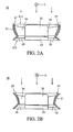
- Figs. 2A and 2B are cross sections of a fan assembly according to a first embodiment of the invention.
- the fan assembly 20 comprises a frame 21, an impeller 24, and a motor (not shown).
- the motor is disposed in a motor base 22 for driving the impeller 25.
- the frame 21 comprises a body with an opening 26 defined therein.
- the periphery 27 of the opening 26 has a curved surface.
- the motor base 22 is disposed in the body of the frame 21 and supported by a plurality of ribs 23.
- the impeller 25 comprises a plurality of radially arranged blades 24.
- the fan assembly 20 for dissipating heat When the fan assembly 20 for dissipating heat is applied to a light source L producing heat such as a light bulb of a projector, light emitted by the light source L enters the opening 26, and the periphery 27 of the opening 26 has a curved surface for blocking the light, and thus, the light is prevented from penetrating the opening 26.
- a light source L producing heat such as a light bulb of a projector
- the periphery 27 of the opening 26 can have a curved surface depressed away from a central axis of the opening 26, as shown in Fig. 2A .
- the curved surface of the periphery 27 gradually contracts, and the blade edges of the impeller 25 correspond to the curved surface of the periphery 27 of the opening.
- Each edge of the blade 24 exceeds an imaginary line connecting the two ends of the curved surface of the periphery 27, namely the upper and lower end of the periphery 27.
- the imaginary line is represented by a dashed line in Fig. 2A .
- the blade edges of the impeller 25 are preferably parallel to the curved surface.
- An inlet 211 and an outlet 212 are respectively formed at two ends of the opening 26 on the frame 21.
- the light emitted by the light source L enters the inlet 211 into the frame 21.
- the periphery 27 of the opening 26 having a concave surface corresponding to the blade edges can prevent light leakage from the outlet 212. Since a possible light path can be completely blocked at the location between the blades 24 and the frame 21, the problem of loss of light in a projector utilizing a conventional fan can be prevented. Furthermore, according to differing curved surfaces of the periphery 27 of the opening 26, the area of the external edge of the blades 24 can be further increased, thereby increasing air pressure.
- the periphery 27 of the opening 26 can have a convex surface protruded toward a central axis of the opening 26, as shown in Fig. 2B .
- the frame 21 has an inwardly concave side, and the blade edges of the impeller 25 correspond to the convex surface of the periphery 27 of the opening 26 to form concave sides separately.
- the concave side edge of each blade 24 is facing and corresponding to the curved surface of the periphery 27.
- the blade edges of the impeller 25 are preferably parallel to the convex surface.
- the protruded convex surface of the periphery 27 of the opening 26 exceeds an imaginary line connecting two ends of the concave side of the blade 24 edges, namely the upper and lower end of the concave side of the blade 24 edges.
- the imaginary line is represented by a dashed line in Fig. 2B .
- the periphery 27 of the opening 26 or a vicinity thereof can be formed with an inclined angle or a guided inclined angle to increase the cross-sectional area of the flow path and increase the air flow intake.
- the curved surface preferably comprises a contracting and an expanding curved surface, or a plurality of radial contracting and expanding curved surfaces in the fan assembly 20 in Fig. 2A or in Fig. 2B . Also, any two adjacent curved surfaces can have different curvature.
- Figs. 3A and 3B are cross sections of a fan assembly serving for a better understanding of the present invention.
- the fan assembly 30 comprises a frame 31, an impeller 35, and a motor (not shown).
- the motor is disposed in a motor base 32 for driving the impeller 35.
- the frame 31 comprises a body with an opening 36 defined thereon.
- the periphery of the opening 36 has at least one inclined surface.
- the motor base 32 is disposed in the body of the frame 31 and supported by a plurality of ribs 33.
- the impeller 35 comprises a plurality of radially arranged blades 34.
- the fan assembly 30 for dissipating heat When the fan assembly 30 for dissipating heat is applied to a light source L producing heat such as a light bulb of a projector, light emitted by the light source L enters the opening 36, and the periphery 37 of the opening 36 has an inclined surface for blocking the light, and thus, the light is prevented from penetrating the opening 36.
- a light source L producing heat such as a light bulb of a projector
- the periphery 37 of the opening 36 comprises multi-sectional inclined surfaces with different inclined angles.
- an inclined surface comprises a radially contracting inclined surface 3A 1 and a radially expanding inclined surface 3A 2 , as shown in Fig. 3A .
- the cross section of the frame 31 is preferably constituted of the contracting inclined surface 3A 1 and the expanding inclined surface 3A 2 from the inlet 311 to the outlet 312.
- An external edge of the blade 34 is parallel to the contracting inclined surface 3A 1 such that light is effectively blocked from penetrating the frame 31.
- the expanding inclined surface 3A 2 increases area of flow path, and increase airflow intake.
- the inclined surface comprises a plurality of a combination of radially contracting inclined surfaces and radially expanding inclined surfaces, and each two adjacent inclined surfaces are connected at different angles.
- the cross section of the frame 31 can be considered as being consisted of several inclined surfaces with different angles, such as two contracting inclined surfaces 3B 1 , 3B 2 , and one expanding inclined surface 3B 3 , from the inlet 311 to the outlet 312.
- the contracting inclined surfaces 3B 1 , 3B 2 can obstruct a potential light path between the blades 34 and the frame 31, and the external edges of the blades 34are parallel to the contracting inclined surfaces 3B 2 .
- the expanding inclined surfaces 3B 3 increase area of the flow path, thereby increasing airflow intake.
- the motor base 32 is disposed in the frame 31 and supported by a plurality of ribs 33.
- the motor base 32 and the ribs 33 can be disposed at the inlet 311 or the outlet 312.
- the motor base 32 comprises a slope inclined radially in order to increase air outflow area, when the motor base 32 and the ribs 33 are disposed at the outlet 312.
- the slope can have a flat surface ( Fig. 3C ) or a curved surface ( Fig. 3D ). If the motor base 32 and the ribs 33 are disposed at the inlet 31 of the frame 31, the inclined motor base 32 can increase inflow area.
- the inclined angle of the motor base 32 can be varied in accordance with different curvature of the cross section of the frame 31 to allow air smoothly flow between the motor base 32 and the frame 31, when the blades 34 rotate, so that noise can be reduced.
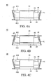
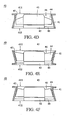
- Figs. 4A to 4F are cross sections of a fan assembly serving for a better understanding of the present invention.
- the fan 40 comprises a frame 41, an impeller 45, and a motor (not shown).
- the motor is disposed in a motor base 42 for driving the impeller 45.
- the frame 41 comprises a body with an opening 46 defined thereon.
- the periphery 47 of the opening 46 comprises at least one inclined surface.
- the motor base 42 is disposed in the frame 41 and supported by a plurality of ribs 43.
- the impeller 45 comprises a plurality of radially arranged blades 44.
- the fan assembly 40 for dissipating heat When the fan assembly 40 for dissipating heat is applied to a light source producing heat such as a light bulb of a projector, light emitted by the light source enters the opening 46, and the periphery 47 of the opening 46 has an inclined surface for blocking the light.
- the blades 44 have a maximum outer diameter greater than the inner diameter of the periphery 47 of the opening 46. As a result, a potential light path between the blades 44 and the frame 41 can be obstructed by an overlapping portion between the blades 44 and the periphery 47 of the opening 46. Thus, the light is prevented from penetrating the opening 46.
- the frame 41 comprises at least one inclined surface or curved surface from an inlet 411 to an outlet 412.
- the cross section of the frame 41 can be gradually contracting curved surface, expanding curved surface or a combination thereof.
- the contracting curved surface obstructs the light path between the blades 44 and the frame 41.
- the expanding curved surface can increase area of the flow path and increase the airflow intake.
- the external edges of the blades can be designed with various shapes in accordance with the frame 41.
- the external edges of the blades can be flat (as shown in Figs. 4C and 4D ), conical (as shown in Figs. 4E and 4F ), stepped shapes (as shown in Figs. 4A and 4B ), and so on.
- each blade 44a also partially overlaps with an adjacent blade 44b in an axial direction of the opening 46, as shown in Fig. 4G.
- Fig. 4G is a top view of the entire fan assembly according to the third embodiment of the invention. The overlapping blades can further effectively block the light.
- Embodiments of the invention are compared to a conventional fan with a light-blocking experiment with the same size of frame from 50mm, 60mm, and 70mm frames in a black box.
- a 3000 Lux. of light irradiates in the black box.
- the amount of light passing through the fans is recorded in Table 1 as follows.
- Table 1 Frame size SQ 50mm SQ 60mm SQ 70mm fan assembly of the present invention 7.2 Lux 4.13 Lux 1.3
- the amount of light passing through the conventional fan assembly is 490 Lux, but the amount of light passing through the fan assembly of the invention designed with light-blocking characteristics is only 7.2 Lux.
- the present invention can block light effectively.
Landscapes
- Engineering & Computer Science (AREA)
- Mechanical Engineering (AREA)
- General Engineering & Computer Science (AREA)
- Structures Of Non-Positive Displacement Pumps (AREA)
- Arrangement Of Elements, Cooling, Sealing, Or The Like Of Lighting Devices (AREA)
Description
- The invention relates to a fan assembly, and in particular to a fan assembly applicable to a light source producing heat.
- With the continuous development of electronic devices, heat dissipation systems become necessary as temperature is significantly increased due to heat produced during operation. If heat is not appropriately dissipated, high temperature causes performance to deteriorate and may cause the electronic devices to fail. Particularly, since the design of semiconductor and integrated circuits (IC) has improved, the integrated circuit size has been reduced and the number of transistors per unit area has substantially increased, further concentrating heat energy. Thus, a heat dissipation system is required to effectively dissipate the excess heat and maintain working temperature.
- A fan assembly is the most popular heat dissipation apparatus.
Fig. 1A is a top view of a conventional fan assembly, andFig. 1B is a cross section ofFig. 1A . As shown inFigs. 1A and 1B , theconventional fan 10 comprises aframe 11, animpeller 15, and a motor (not shown). The motor is disposed in amotor base 12 to drive theimpeller 15. Theframe 11 comprises a body with an opening defined therein. Themotor base 12 disposed in the frame11 is supported by a plurality ofribs 13. Theribs 13 can be cylindrical, arced, or streamlined. Theimpeller 15 comprises a plurality of radially arrangedblades 14. - As shown in
Fig. 1B , as known, when tworibs 13 are both connected to themotor base 12 and theframe 11, they are not located along the same diameter of theimpeller 15, and the cross section of the tworibs 13 would be discontinuous. For clear illustration, however, the ribs are shown in their entirety inFig. 1B . - During rotation of the
impeller 15, a gap is formed between theframe 11 and theblades 14 to prevent contact therebetween, which produces friction and noise, as shown inFig. 1A . If thefan assembly 10, however, is applied to an optical machine to dissipate heat of the light source (lamp) L, the emitted light Lp may partially penetrate the gap between theframe 11 and theblades 14, causing light loss, as shown inFig. 1B . Consequently, the projected light intensity is reduced, and if escaped light Lp continuously illuminates other areas or objects such as a desk, the surface of the desk can be damaged by the light. The escaped light not only damages the surroundings but also causes safety concerns. -
GB 1 168 756 A -
US 4,365,187 discloses a fan having a similar design. More specifically, the inner peripheral wall of the fan frame firstly extends inwards and then radially outwards but is always straight-lined. The front (outer) edge of the impeller blades has a corresponding shape and is also straight-lined. -
US 2002/0003381 A1 discloses another fan frame, wherein the front (outer) edge of the impeller blade is concave but is not correspondingly shaped to the inner peripheral wall of the fan frame. Particularly, a gap between the inner peripheral wall of the fan frame and the front (outer) edge of the impeller blade is not constant but converging or funnel-shaped. - It is an object of the present invention to provide an enhanced fan assembly enabling an efficient light blocking effect while efficiently dissipating heat.
- This problem is solved by a fan assembly according to
claim - Embodiments of the invention provide a fan assembly with various frames and corresponding blade edge designs to fully obstruct a light path between the blades and the frame, for preventing loss of light and being applicable to a light source that produces heat.
- The fan assembly comprises a frame and an impeller. The frame comprises an opening and a periphery of the opening has a curved surface. The impeller is disposed in the body. When light emitted by the light source enters the opening, the light is blocked from penetrating the opening by the curved surface. Moreover, the opening of the body comprises an inlet and an outlet, the emitted light entering the inlet is blocked by the curved surface, preventing light emission from out of the outlet.
- According to a further embodiment a periphery of the opening has at least one inclined surface. The impeller is disposed in the body. When light emitted by the light source enters the opening of the frame, the light is blocked from penetrating the opening by the inclined surface. The periphery of the opening comprises multi-sectional inclined surfaces with different inclined angles. The impeller comprises blade edges, parallel to the multi-sectional inclined surfaces. Moreover, the periphery of the opening comprises multi-sectional inclined surfaces, protruded toward a central axis of the opening, and the impeller comprises blade edges facing the concave sides of the multi-sectional inclined surfaces, and the periphery of the opening exceeds a line connected by two ends of the concave sides.
- Embodiments of the invention can be more fully understood by reading the subsequent detailed description in conjunction with the examples and references made to the accompanying drawings, wherein:
-
Fig. 1A is a top view of a conventional fan assembly; -
Fig. 1B is a cross section of the conventional fan assembly; -
Figs. 2A and 2B are cross sections of two fan assemblies according to the invention; -
Figs. 3A to Fig. 4G show examples of fan assemblies serving for a better understanding of the present invention. -
Figs. 2A and 2B are cross sections of a fan assembly according to a first embodiment of the invention. Thefan assembly 20 comprises aframe 21, animpeller 24, and a motor (not shown). The motor is disposed in amotor base 22 for driving theimpeller 25. Theframe 21 comprises a body with anopening 26 defined therein. Theperiphery 27 of theopening 26 has a curved surface. Themotor base 22 is disposed in the body of theframe 21 and supported by a plurality ofribs 23. Theimpeller 25 comprises a plurality of radially arrangedblades 24. - When the
fan assembly 20 for dissipating heat is applied to a light source L producing heat such as a light bulb of a projector, light emitted by the light source L enters theopening 26, and theperiphery 27 of theopening 26 has a curved surface for blocking the light, and thus, the light is prevented from penetrating theopening 26. - The
periphery 27 of theopening 26 can have a curved surface depressed away from a central axis of theopening 26, as shown inFig. 2A . The curved surface of theperiphery 27 gradually contracts, and the blade edges of theimpeller 25 correspond to the curved surface of theperiphery 27 of the opening. Each edge of theblade 24 exceeds an imaginary line connecting the two ends of the curved surface of theperiphery 27, namely the upper and lower end of theperiphery 27. The imaginary line is represented by a dashed line inFig. 2A . The blade edges of theimpeller 25 are preferably parallel to the curved surface. - An
inlet 211 and anoutlet 212 are respectively formed at two ends of theopening 26 on theframe 21. The light emitted by the light source L enters theinlet 211 into theframe 21. Theperiphery 27 of theopening 26 having a concave surface corresponding to the blade edges can prevent light leakage from theoutlet 212. Since a possible light path can be completely blocked at the location between theblades 24 and theframe 21, the problem of loss of light in a projector utilizing a conventional fan can be prevented. Furthermore, according to differing curved surfaces of theperiphery 27 of theopening 26, the area of the external edge of theblades 24 can be further increased, thereby increasing air pressure. - Alternatively, the
periphery 27 of theopening 26 can have a convex surface protruded toward a central axis of theopening 26, as shown inFig. 2B . Theframe 21 has an inwardly concave side, and the blade edges of theimpeller 25 correspond to the convex surface of theperiphery 27 of theopening 26 to form concave sides separately. The concave side edge of eachblade 24 is facing and corresponding to the curved surface of theperiphery 27. The blade edges of theimpeller 25 are preferably parallel to the convex surface. The protruded convex surface of theperiphery 27 of theopening 26 exceeds an imaginary line connecting two ends of the concave side of theblade 24 edges, namely the upper and lower end of the concave side of theblade 24 edges. The imaginary line is represented by a dashed line inFig. 2B . Thus, when the light is emitted by the light source L, the light can be blocked from penetrating theframe 21, since the protruded surface of theperiphery 27 of theopening 26 corresponds to the blade edges. - Furthermore, at the
inlet 211 and theoutlet 212 of thefan assembly 20 shown inFigs. 2A and 2B , theperiphery 27 of theopening 26 or a vicinity thereof can be formed with an inclined angle or a guided inclined angle to increase the cross-sectional area of the flow path and increase the air flow intake. Moreover, the curved surface preferably comprises a contracting and an expanding curved surface, or a plurality of radial contracting and expanding curved surfaces in thefan assembly 20 inFig. 2A or inFig. 2B . Also, any two adjacent curved surfaces can have different curvature. -
Figs. 3A and 3B are cross sections of a fan assembly serving for a better understanding of the present invention. Thefan assembly 30 comprises aframe 31, animpeller 35, and a motor (not shown). The motor is disposed in amotor base 32 for driving theimpeller 35. Theframe 31 comprises a body with anopening 36 defined thereon. The periphery of theopening 36 has at least one inclined surface. Themotor base 32 is disposed in the body of theframe 31 and supported by a plurality ofribs 33. Theimpeller 35 comprises a plurality of radially arrangedblades 34. - When the
fan assembly 30 for dissipating heat is applied to a light source L producing heat such as a light bulb of a projector, light emitted by the light source L enters theopening 36, and theperiphery 37 of theopening 36 has an inclined surface for blocking the light, and thus, the light is prevented from penetrating theopening 36. - The
periphery 37 of theopening 36 comprises multi-sectional inclined surfaces with different inclined angles. For example, an inclined surface comprises a radially contracting inclined surface 3A1 and a radially expanding inclined surface 3A2, as shown inFig. 3A . The cross section of theframe 31 is preferably constituted of the contracting inclined surface 3A1 and the expanding inclined surface 3A2 from theinlet 311 to theoutlet 312. An external edge of theblade 34 is parallel to the contracting inclined surface 3A1 such that light is effectively blocked from penetrating theframe 31. Also, the expanding inclined surface 3A2 increases area of flow path, and increase airflow intake. - Additionally, the inclined surface comprises a plurality of a combination of radially contracting inclined surfaces and radially expanding inclined surfaces, and each two adjacent inclined surfaces are connected at different angles. For example, as shown in
Fig. 3B , the cross section of theframe 31 can be considered as being consisted of several inclined surfaces with different angles, such as two contracting inclined surfaces 3B1, 3B2, and one expanding inclined surface 3B3, from theinlet 311 to theoutlet 312. The contracting inclined surfaces 3B1, 3B2 can obstruct a potential light path between theblades 34 and theframe 31, and the external edges of the blades 34are parallel to the contracting inclined surfaces 3B2. Also, the expanding inclined surfaces 3B3 increase area of the flow path, thereby increasing airflow intake. - Furthermore, as shown in
Figs. 3C and 3D , themotor base 32 is disposed in theframe 31 and supported by a plurality ofribs 33. Themotor base 32 and theribs 33 can be disposed at theinlet 311 or theoutlet 312. InFigs. 3C and 3D , themotor base 32 comprises a slope inclined radially in order to increase air outflow area, when themotor base 32 and theribs 33 are disposed at theoutlet 312. The slope can have a flat surface (Fig. 3C ) or a curved surface (Fig. 3D ). If themotor base 32 and theribs 33 are disposed at theinlet 31 of theframe 31, theinclined motor base 32 can increase inflow area. - Furthermore, the inclined angle of the
motor base 32 can be varied in accordance with different curvature of the cross section of theframe 31 to allow air smoothly flow between themotor base 32 and theframe 31, when theblades 34 rotate, so that noise can be reduced. -
Figs. 4A to 4F are cross sections of a fan assembly serving for a better understanding of the present invention. Thefan 40 comprises aframe 41, animpeller 45, and a motor (not shown). The motor is disposed in amotor base 42 for driving theimpeller 45. Theframe 41 comprises a body with anopening 46 defined thereon. Theperiphery 47 of theopening 46 comprises at least one inclined surface. Themotor base 42 is disposed in theframe 41 and supported by a plurality ofribs 43. Theimpeller 45 comprises a plurality of radially arrangedblades 44. - When the
fan assembly 40 for dissipating heat is applied to a light source producing heat such as a light bulb of a projector, light emitted by the light source enters theopening 46, and theperiphery 47 of theopening 46 has an inclined surface for blocking the light. Theblades 44 have a maximum outer diameter greater than the inner diameter of theperiphery 47 of theopening 46. As a result, a potential light path between theblades 44 and theframe 41 can be obstructed by an overlapping portion between theblades 44 and theperiphery 47 of theopening 46. Thus, the light is prevented from penetrating theopening 46. - The
frame 41 comprises at least one inclined surface or curved surface from aninlet 411 to anoutlet 412. The cross section of theframe 41 can be gradually contracting curved surface, expanding curved surface or a combination thereof. The contracting curved surface obstructs the light path between theblades 44 and theframe 41. The expanding curved surface can increase area of the flow path and increase the airflow intake. Furthermore, the external edges of the blades can be designed with various shapes in accordance with theframe 41. For example, the external edges of the blades can be flat (as shown inFigs. 4C and4D ), conical (as shown inFigs. 4E and 4F ), stepped shapes (as shown inFigs. 4A and 4B ), and so on. - The invention is not limited to the above embodiment. Moreover, the
blades 44 not only have maximum outer diameter greater than a minimum inner diameter of theperiphery 47 of theopening 46, eachblade 44a also partially overlaps with anadjacent blade 44b in an axial direction of theopening 46, as shown inFig. 4G. Fig. 4G is a top view of the entire fan assembly according to the third embodiment of the invention. The overlapping blades can further effectively block the light. - Embodiments of the invention are compared to a conventional fan with a light-blocking experiment with the same size of frame from 50mm, 60mm, and 70mm frames in a black box. A 3000 Lux. of light irradiates in the black box. The amount of light passing through the fans is recorded in Table 1 as follows.
Table 1 Frame size SQ 50mm SQ 60mm SQ 70mm fan assembly of the present invention 7.2 Lux 4.13 Lux 1.3 Lux conventional fan assembly 490 Lux 329 Lux 318 Lux - In a 50mm-sized frame, the amount of light passing through the conventional fan assembly is 490 Lux, but the amount of light passing through the fan assembly of the invention designed with light-blocking characteristics is only 7.2 Lux. Thus it demonstrates that the present invention can block light effectively.
- While the invention has been described by way of example and in terms of preferred embodiment, it is to be understood that the invention is not limited thereto. To the contrary, it is intended to cover various modifications and similar arrangements (as would be apparent to those skilled in the art). Therefore, the scope is defined by the appended claims.
Claims (19)
- A fan assembly, applicable to a light source producing heat, the fan assembly comprising:a frame (21) comprising an opening (26) and a periphery (27) of the opening having a curved surface; andan impeller (25), disposed in the frame and comprising a plurality of radially extending blades (24);characterized in thatthe curved surface comprises a concave surface, which is depressed away from a central axis of the opening, and blade edges of the impeller correspond to the curved surface of the periphery of the opening and exceed an imaginary line connecting two ends of the curved surface, orthe curved surface comprises a convex surface, which is protruded toward a central axis of the opening and blade edges of the impeller correspond to the convex surface of the periphery of the curved surface to form concave sides facing the curved surface of the opening, and the curved surface of the periphery of the opening exceed an imaginary line connecting two ends of a respective concave side of the impellerso that light emitted by the light source and entering the opening is blocked from penetrating the opening by the curved surface.
- The fan assembly as claimed in claim 1, wherein the opening (26) forms an inlet (211) and an outlet (212) of the frame, and the emitted light entering the inlet is blocked from emitting out of the outlet by the curved surface.
- The fan assembly as claimed in claim 2, wherein the periphery (27) of the opening comprises an inclined angle at the inlet or the outlet, or a vicinity of the periphery comprises a guided inclined angle.
- The fan assembly as claimed in any of the preceding claims, wherein blade edges of the impeller extend in parallel to the curved surface.
- The fan assembly as claimed in any of the preceding claims, wherein the curved surface comprises a contracting curved surface and an expanding curved surface.
- The fan assembly as claimed in any of the preceding claims, further comprising a motor base (22) disposed in the frame, and a plurality of ribs (23) for supporting the motor base; wherein the motor base comprises a slope inclined radially, thereby increasing areas of air flow intake or outtake.
- The fan assembly as claimed in claim 6, wherein the slope is flat or curved.
- The fan assembly as claimed in any of the preceding claims, wherein the impeller has blades with a maximum outer diameter greater than a minimum inner diameter of the periphery of the opening.
- The fan assembly as claimed in claim 8, wherein the impeller comprises blades with flat, conical, or stepped edges.
- The fan assembly as claimed in claim 9, wherein each blade of the impeller overlaps an adjacent blade in an axial direction of the opening.
- A fan assembly, applied to a light source producing heat, the fan assembly comprising:a frame comprising an opening, and a periphery of the opening having at least one inclined surface; andan impeller, disposed in the frame and comprising a plurality of radially extending blades;characterized in that the periphery of the opening comprises multi-sectional inclined surfaces having convex sides, protruded toward a central axis of the opening, the impeller comprises blade edges and concave surfaces facing the convex sides of the multi-sectional inclined surfaces, and the convex sides of the periphery of the opening exceed a line connecting two ends of a respective concave surface of the impeller so that light emitted by the light source and entering the opening is blocked from penetrating the opening by the inclined surface.
- The fan assembly as claimed in claim 11, wherein the periphery of the opening comprises multi-sectional inclined surfaces with different inclined angles.
- The fan assembly as claimed in claim 11 or 12, wherein the impeller comprises blade edges, parallel to the multi-sectional inclined surfaces.
- The fan assembly as claimed in any of claims 11 to 13, wherein the periphery of the opening comprises multi-sectional inclined surfaces, depressed toward a central axis of the opening, and the impeller comprises blade edges exceeding a line connected by two ends of the opening.
- The fan assembly as claimed any in claims 11 to 14, wherein the periphery of the opening comprises an expanding inclined surface.
- The fan assembly as claimed in any of claims 11 to 15, further comprising a motor base disposed in the frame, and a plurality of ribs for supporting the motor base; wherein the motor base comprises a flat or curved slope inclined radially, thereby increasing areas of air flow intake or outtake.
- The fan assembly as claimed in any of claims 11 to 16, wherein the impeller has blades with a maximum outer diameter greater than a minimum inner diameter of the periphery of the opening.
- The fan assembly as claimed in any of claims 11 to 17, wherein the impeller comprises blades with flat, conical, or stepped edges.
- The fan assembly as claimed in any of claims 11 to 18, wherein each blade of the impeller overlaps an adjacent blade in an axial direction of the opening.
Applications Claiming Priority (1)
| Application Number | Priority Date | Filing Date | Title |
|---|---|---|---|
| CNB2004100700005A CN100398839C (en) | 2004-07-20 | 2004-07-20 | shade fan |
Publications (3)
| Publication Number | Publication Date |
|---|---|
| EP1619394A2 EP1619394A2 (en) | 2006-01-25 |
| EP1619394A3 EP1619394A3 (en) | 2011-10-19 |
| EP1619394B1 true EP1619394B1 (en) | 2013-05-29 |
Family
ID=34930025
Family Applications (1)
| Application Number | Title | Priority Date | Filing Date |
|---|---|---|---|
| EP20040106433 Expired - Lifetime EP1619394B1 (en) | 2004-07-20 | 2004-12-09 | Fan assembly |
Country Status (2)
| Country | Link |
|---|---|
| EP (1) | EP1619394B1 (en) |
| CN (1) | CN100398839C (en) |
Families Citing this family (3)
| Publication number | Priority date | Publication date | Assignee | Title |
|---|---|---|---|---|
| CN101265923B (en) * | 2007-03-14 | 2011-09-14 | 台达电子工业股份有限公司 | Fan and its frame |
| EP3239533A1 (en) * | 2016-04-29 | 2017-11-01 | STEINBEIS GMBH & CO. Für TECHNOLOGIETRANSFER | Axial turbomachine |
| WO2019012880A1 (en) * | 2017-07-11 | 2019-01-17 | 日本電産株式会社 | Fan device |
Family Cites Families (8)
| Publication number | Priority date | Publication date | Assignee | Title |
|---|---|---|---|---|
| DE1549776A1 (en) | 1967-08-18 | 1971-05-06 | Ibm Deutschland | Print hammer drive device |
| US4365187A (en) * | 1980-05-15 | 1982-12-21 | Rotron Incorporated | Brushless D.C. motor |
| DE3542214A1 (en) * | 1984-12-03 | 1986-06-05 | Papst-Motoren GmbH & Co KG, 7742 St Georgen | Fan |
| MXPA02010777A (en) * | 2000-05-03 | 2003-03-27 | Horton Inc | A cooling system with brushless dc ring motor fan. |
| TW514350U (en) * | 2001-06-22 | 2002-12-11 | Coretronic Corp | Projecting device with heat-dissipating fan |
| JP2003140268A (en) * | 2001-11-02 | 2003-05-14 | Sanyo Electric Co Ltd | Fan device and projection type display using the fan device |
| JP4346845B2 (en) * | 2001-11-27 | 2009-10-21 | パナソニック株式会社 | Shading fan |
| CN2588416Y (en) * | 2002-10-31 | 2003-11-26 | 大亿科技股份有限公司 | Projector with blackout effect |
-
2004
- 2004-07-20 CN CNB2004100700005A patent/CN100398839C/en not_active Expired - Lifetime
- 2004-12-09 EP EP20040106433 patent/EP1619394B1/en not_active Expired - Lifetime
Also Published As
| Publication number | Publication date |
|---|---|
| EP1619394A2 (en) | 2006-01-25 |
| CN1724876A (en) | 2006-01-25 |
| EP1619394A3 (en) | 2011-10-19 |
| CN100398839C (en) | 2008-07-02 |
Similar Documents
| Publication | Publication Date | Title |
|---|---|---|
| ES2914227T3 (en) | Floor Standing Air Conditioner and Scroll Fan Assembly Frame | |
| US7391611B2 (en) | Heat-dissipating device and a housing thereof | |
| US20030000684A1 (en) | Heat dissipation device with high efficiency | |
| US7241110B2 (en) | Centrifugal fan with stator blades | |
| JP6442216B2 (en) | Ventilation assembly | |
| US8128359B2 (en) | Air fan module and a flow directing blade assembly thereof | |
| US20060045738A1 (en) | Fan | |
| JP2006046317A (en) | Structure of centrifugal radiation fan | |
| US8324766B2 (en) | Heat-dissipation structure for motor | |
| US20160073550A1 (en) | Fan comprising a printed circuit board cooling circuit | |
| US7380955B2 (en) | Fan assembly | |
| US7118345B2 (en) | Fan blade | |
| US20060045774A1 (en) | Fans and fan frames | |
| US7018175B2 (en) | Airflow guiding structure for a heat dissipation fan | |
| US7275910B2 (en) | Outlet airflow direction control unit | |
| US20060051221A1 (en) | Heat-dissipation structure for motor | |
| US20020079086A1 (en) | Embedded centrifugal cooling device | |
| EP1619394A2 (en) | Fan assembly | |
| JP2006207519A (en) | Centrifugal fan | |
| US6960059B2 (en) | Blower with a plurality of impellers | |
| JP2005309430A (en) | Projection optics module and its shading fan | |
| US7094028B2 (en) | Outlet airflow direction control device | |
| US7607782B2 (en) | Projection apparatus provided with a cooling system | |
| EP1659843B1 (en) | Fans and fan frames | |
| US12448984B2 (en) | Centrifugal fan |
Legal Events
| Date | Code | Title | Description |
|---|---|---|---|
| PUAI | Public reference made under article 153(3) epc to a published international application that has entered the european phase |
Free format text: ORIGINAL CODE: 0009012 |
|
| AK | Designated contracting states |
Kind code of ref document: A2 Designated state(s): AT BE BG CH CY CZ DE DK EE ES FI FR GB GR HU IE IS IT LI LT LU MC NL PL PT RO SE SI SK TR |
|
| AX | Request for extension of the european patent |
Extension state: AL BA HR LV MK YU |
|
| 17P | Request for examination filed |
Effective date: 20060627 |
|
| PUAL | Search report despatched |
Free format text: ORIGINAL CODE: 0009013 |
|
| AK | Designated contracting states |
Kind code of ref document: A3 Designated state(s): AT BE BG CH CY CZ DE DK EE ES FI FR GB GR HU IE IS IT LI LT LU MC NL PL PT RO SE SI SK TR |
|
| AX | Request for extension of the european patent |
Extension state: AL BA HR LV MK YU |
|
| RIC1 | Information provided on ipc code assigned before grant |
Ipc: F04D 25/08 20060101ALI20110915BHEP Ipc: F04D 29/54 20060101AFI20110915BHEP |
|
| AKX | Designation fees paid |
Designated state(s): AT BE BG CH CY CZ DE DK EE ES FI FR GB GR HU IE IS IT LI LT LU MC NL PL PT RO SE SI SK TR |
|
| 17Q | First examination report despatched |
Effective date: 20120625 |
|
| GRAP | Despatch of communication of intention to grant a patent |
Free format text: ORIGINAL CODE: EPIDOSNIGR1 |
|
| GRAS | Grant fee paid |
Free format text: ORIGINAL CODE: EPIDOSNIGR3 |
|
| GRAA | (expected) grant |
Free format text: ORIGINAL CODE: 0009210 |
|
| AK | Designated contracting states |
Kind code of ref document: B1 Designated state(s): AT BE BG CH CY CZ DE DK EE ES FI FR GB GR HU IE IS IT LI LT LU MC NL PL PT RO SE SI SK TR |
|
| REG | Reference to a national code |
Ref country code: GB Ref legal event code: FG4D |
|
| REG | Reference to a national code |
Ref country code: CH Ref legal event code: EP |
|
| REG | Reference to a national code |
Ref country code: AT Ref legal event code: REF Ref document number: 614577 Country of ref document: AT Kind code of ref document: T Effective date: 20130615 |
|
| REG | Reference to a national code |
Ref country code: IE Ref legal event code: FG4D |
|
| REG | Reference to a national code |
Ref country code: DE Ref legal event code: R096 Ref document number: 602004042277 Country of ref document: DE Effective date: 20130725 |
|
| REG | Reference to a national code |
Ref country code: AT Ref legal event code: MK05 Ref document number: 614577 Country of ref document: AT Kind code of ref document: T Effective date: 20130529 |
|
| REG | Reference to a national code |
Ref country code: LT Ref legal event code: MG4D |
|
| PG25 | Lapsed in a contracting state [announced via postgrant information from national office to epo] |
Ref country code: IS Free format text: LAPSE BECAUSE OF FAILURE TO SUBMIT A TRANSLATION OF THE DESCRIPTION OR TO PAY THE FEE WITHIN THE PRESCRIBED TIME-LIMIT Effective date: 20130929 Ref country code: AT Free format text: LAPSE BECAUSE OF FAILURE TO SUBMIT A TRANSLATION OF THE DESCRIPTION OR TO PAY THE FEE WITHIN THE PRESCRIBED TIME-LIMIT Effective date: 20130529 Ref country code: ES Free format text: LAPSE BECAUSE OF FAILURE TO SUBMIT A TRANSLATION OF THE DESCRIPTION OR TO PAY THE FEE WITHIN THE PRESCRIBED TIME-LIMIT Effective date: 20130909 Ref country code: SE Free format text: LAPSE BECAUSE OF FAILURE TO SUBMIT A TRANSLATION OF THE DESCRIPTION OR TO PAY THE FEE WITHIN THE PRESCRIBED TIME-LIMIT Effective date: 20130529 Ref country code: LT Free format text: LAPSE BECAUSE OF FAILURE TO SUBMIT A TRANSLATION OF THE DESCRIPTION OR TO PAY THE FEE WITHIN THE PRESCRIBED TIME-LIMIT Effective date: 20130529 Ref country code: PT Free format text: LAPSE BECAUSE OF FAILURE TO SUBMIT A TRANSLATION OF THE DESCRIPTION OR TO PAY THE FEE WITHIN THE PRESCRIBED TIME-LIMIT Effective date: 20130930 Ref country code: GR Free format text: LAPSE BECAUSE OF FAILURE TO SUBMIT A TRANSLATION OF THE DESCRIPTION OR TO PAY THE FEE WITHIN THE PRESCRIBED TIME-LIMIT Effective date: 20130830 Ref country code: SI Free format text: LAPSE BECAUSE OF FAILURE TO SUBMIT A TRANSLATION OF THE DESCRIPTION OR TO PAY THE FEE WITHIN THE PRESCRIBED TIME-LIMIT Effective date: 20130529 Ref country code: FI Free format text: LAPSE BECAUSE OF FAILURE TO SUBMIT A TRANSLATION OF THE DESCRIPTION OR TO PAY THE FEE WITHIN THE PRESCRIBED TIME-LIMIT Effective date: 20130529 |
|
| REG | Reference to a national code |
Ref country code: NL Ref legal event code: VDEP Effective date: 20130529 |
|
| PG25 | Lapsed in a contracting state [announced via postgrant information from national office to epo] |
Ref country code: BG Free format text: LAPSE BECAUSE OF FAILURE TO SUBMIT A TRANSLATION OF THE DESCRIPTION OR TO PAY THE FEE WITHIN THE PRESCRIBED TIME-LIMIT Effective date: 20130829 Ref country code: PL Free format text: LAPSE BECAUSE OF FAILURE TO SUBMIT A TRANSLATION OF THE DESCRIPTION OR TO PAY THE FEE WITHIN THE PRESCRIBED TIME-LIMIT Effective date: 20130529 |
|
| PG25 | Lapsed in a contracting state [announced via postgrant information from national office to epo] |
Ref country code: DK Free format text: LAPSE BECAUSE OF FAILURE TO SUBMIT A TRANSLATION OF THE DESCRIPTION OR TO PAY THE FEE WITHIN THE PRESCRIBED TIME-LIMIT Effective date: 20130529 Ref country code: SK Free format text: LAPSE BECAUSE OF FAILURE TO SUBMIT A TRANSLATION OF THE DESCRIPTION OR TO PAY THE FEE WITHIN THE PRESCRIBED TIME-LIMIT Effective date: 20130529 Ref country code: EE Free format text: LAPSE BECAUSE OF FAILURE TO SUBMIT A TRANSLATION OF THE DESCRIPTION OR TO PAY THE FEE WITHIN THE PRESCRIBED TIME-LIMIT Effective date: 20130529 Ref country code: BE Free format text: LAPSE BECAUSE OF FAILURE TO SUBMIT A TRANSLATION OF THE DESCRIPTION OR TO PAY THE FEE WITHIN THE PRESCRIBED TIME-LIMIT Effective date: 20130529 Ref country code: CZ Free format text: LAPSE BECAUSE OF FAILURE TO SUBMIT A TRANSLATION OF THE DESCRIPTION OR TO PAY THE FEE WITHIN THE PRESCRIBED TIME-LIMIT Effective date: 20130529 |
|
| PG25 | Lapsed in a contracting state [announced via postgrant information from national office to epo] |
Ref country code: NL Free format text: LAPSE BECAUSE OF FAILURE TO SUBMIT A TRANSLATION OF THE DESCRIPTION OR TO PAY THE FEE WITHIN THE PRESCRIBED TIME-LIMIT Effective date: 20130529 Ref country code: IT Free format text: LAPSE BECAUSE OF FAILURE TO SUBMIT A TRANSLATION OF THE DESCRIPTION OR TO PAY THE FEE WITHIN THE PRESCRIBED TIME-LIMIT Effective date: 20130529 Ref country code: RO Free format text: LAPSE BECAUSE OF FAILURE TO SUBMIT A TRANSLATION OF THE DESCRIPTION OR TO PAY THE FEE WITHIN THE PRESCRIBED TIME-LIMIT Effective date: 20130529 |
|
| PLBE | No opposition filed within time limit |
Free format text: ORIGINAL CODE: 0009261 |
|
| STAA | Information on the status of an ep patent application or granted ep patent |
Free format text: STATUS: NO OPPOSITION FILED WITHIN TIME LIMIT |
|
| 26N | No opposition filed |
Effective date: 20140303 |
|
| REG | Reference to a national code |
Ref country code: DE Ref legal event code: R097 Ref document number: 602004042277 Country of ref document: DE Effective date: 20140303 |
|
| REG | Reference to a national code |
Ref country code: CH Ref legal event code: PL |
|
| PG25 | Lapsed in a contracting state [announced via postgrant information from national office to epo] |
Ref country code: LU Free format text: LAPSE BECAUSE OF FAILURE TO SUBMIT A TRANSLATION OF THE DESCRIPTION OR TO PAY THE FEE WITHIN THE PRESCRIBED TIME-LIMIT Effective date: 20131209 Ref country code: MC Free format text: LAPSE BECAUSE OF FAILURE TO SUBMIT A TRANSLATION OF THE DESCRIPTION OR TO PAY THE FEE WITHIN THE PRESCRIBED TIME-LIMIT Effective date: 20130529 |
|
| REG | Reference to a national code |
Ref country code: IE Ref legal event code: MM4A |
|
| PG25 | Lapsed in a contracting state [announced via postgrant information from national office to epo] |
Ref country code: IE Free format text: LAPSE BECAUSE OF NON-PAYMENT OF DUE FEES Effective date: 20131209 Ref country code: LI Free format text: LAPSE BECAUSE OF NON-PAYMENT OF DUE FEES Effective date: 20131231 Ref country code: CH Free format text: LAPSE BECAUSE OF NON-PAYMENT OF DUE FEES Effective date: 20131231 |
|
| PG25 | Lapsed in a contracting state [announced via postgrant information from national office to epo] |
Ref country code: TR Free format text: LAPSE BECAUSE OF FAILURE TO SUBMIT A TRANSLATION OF THE DESCRIPTION OR TO PAY THE FEE WITHIN THE PRESCRIBED TIME-LIMIT Effective date: 20130529 Ref country code: CY Free format text: LAPSE BECAUSE OF FAILURE TO SUBMIT A TRANSLATION OF THE DESCRIPTION OR TO PAY THE FEE WITHIN THE PRESCRIBED TIME-LIMIT Effective date: 20130529 |
|
| PG25 | Lapsed in a contracting state [announced via postgrant information from national office to epo] |
Ref country code: HU Free format text: LAPSE BECAUSE OF FAILURE TO SUBMIT A TRANSLATION OF THE DESCRIPTION OR TO PAY THE FEE WITHIN THE PRESCRIBED TIME-LIMIT; INVALID AB INITIO Effective date: 20041209 |
|
| REG | Reference to a national code |
Ref country code: FR Ref legal event code: PLFP Year of fee payment: 12 |
|
| REG | Reference to a national code |
Ref country code: FR Ref legal event code: PLFP Year of fee payment: 13 |
|
| REG | Reference to a national code |
Ref country code: FR Ref legal event code: PLFP Year of fee payment: 14 |
|
| PGFP | Annual fee paid to national office [announced via postgrant information from national office to epo] |
Ref country code: GB Payment date: 20201228 Year of fee payment: 17 Ref country code: FR Payment date: 20201227 Year of fee payment: 17 |
|
| PGFP | Annual fee paid to national office [announced via postgrant information from national office to epo] |
Ref country code: DE Payment date: 20201229 Year of fee payment: 17 |
|
| REG | Reference to a national code |
Ref country code: DE Ref legal event code: R119 Ref document number: 602004042277 Country of ref document: DE |
|
| GBPC | Gb: european patent ceased through non-payment of renewal fee |
Effective date: 20211209 |
|
| PG25 | Lapsed in a contracting state [announced via postgrant information from national office to epo] |
Ref country code: GB Free format text: LAPSE BECAUSE OF NON-PAYMENT OF DUE FEES Effective date: 20211209 Ref country code: DE Free format text: LAPSE BECAUSE OF NON-PAYMENT OF DUE FEES Effective date: 20220701 |
|
| PG25 | Lapsed in a contracting state [announced via postgrant information from national office to epo] |
Ref country code: FR Free format text: LAPSE BECAUSE OF NON-PAYMENT OF DUE FEES Effective date: 20211231 |