EP1619392B1 - Fan blades - Google Patents
Fan blades Download PDFInfo
- Publication number
- EP1619392B1 EP1619392B1 EP05250654.0A EP05250654A EP1619392B1 EP 1619392 B1 EP1619392 B1 EP 1619392B1 EP 05250654 A EP05250654 A EP 05250654A EP 1619392 B1 EP1619392 B1 EP 1619392B1
- Authority
- EP
- European Patent Office
- Prior art keywords
- fan blade
- fan
- approximately
- radius
- ellipse
- Prior art date
- Legal status (The legal status is an assumption and is not a legal conclusion. Google has not performed a legal analysis and makes no representation as to the accuracy of the status listed.)
- Expired - Lifetime
Links
- 229910052782 aluminium Inorganic materials 0.000 claims description 2
- XAGFODPZIPBFFR-UHFFFAOYSA-N aluminium Chemical compound [Al] XAGFODPZIPBFFR-UHFFFAOYSA-N 0.000 claims description 2
- 230000001419 dependent effect Effects 0.000 claims description 2
- 230000004048 modification Effects 0.000 description 7
- 238000012986 modification Methods 0.000 description 7
- 239000000463 material Substances 0.000 description 5
- 239000000356 contaminant Substances 0.000 description 4
- 230000001965 increasing effect Effects 0.000 description 4
- 238000004519 manufacturing process Methods 0.000 description 4
- 238000000034 method Methods 0.000 description 4
- 238000009826 distribution Methods 0.000 description 3
- 238000005265 energy consumption Methods 0.000 description 3
- 239000000853 adhesive Substances 0.000 description 2
- 230000001070 adhesive effect Effects 0.000 description 2
- 230000002939 deleterious effect Effects 0.000 description 2
- 230000000694 effects Effects 0.000 description 2
- 229910052751 metal Inorganic materials 0.000 description 2
- 239000002184 metal Substances 0.000 description 2
- 239000004033 plastic Substances 0.000 description 2
- 238000003466 welding Methods 0.000 description 2
- 238000005452 bending Methods 0.000 description 1
- 230000036760 body temperature Effects 0.000 description 1
- 238000002485 combustion reaction Methods 0.000 description 1
- 238000001816 cooling Methods 0.000 description 1
- 238000010790 dilution Methods 0.000 description 1
- 239000012895 dilution Substances 0.000 description 1
- 238000006073 displacement reaction Methods 0.000 description 1
- 230000002708 enhancing effect Effects 0.000 description 1
- 231100001261 hazardous Toxicity 0.000 description 1
- 238000010438 heat treatment Methods 0.000 description 1
- 230000005764 inhibitory process Effects 0.000 description 1
- 230000002452 interceptive effect Effects 0.000 description 1
- 244000144972 livestock Species 0.000 description 1
- 239000002991 molded plastic Substances 0.000 description 1
- 238000000465 moulding Methods 0.000 description 1
- 238000004513 sizing Methods 0.000 description 1
- 238000013517 stratification Methods 0.000 description 1
Images





Classifications
-
- F—MECHANICAL ENGINEERING; LIGHTING; HEATING; WEAPONS; BLASTING
- F04—POSITIVE - DISPLACEMENT MACHINES FOR LIQUIDS; PUMPS FOR LIQUIDS OR ELASTIC FLUIDS
- F04D—NON-POSITIVE-DISPLACEMENT PUMPS
- F04D29/00—Details, component parts, or accessories
- F04D29/26—Rotors specially for elastic fluids
- F04D29/32—Rotors specially for elastic fluids for axial flow pumps
- F04D29/38—Blades
- F04D29/384—Blades characterised by form
-
- F—MECHANICAL ENGINEERING; LIGHTING; HEATING; WEAPONS; BLASTING
- F04—POSITIVE - DISPLACEMENT MACHINES FOR LIQUIDS; PUMPS FOR LIQUIDS OR ELASTIC FLUIDS
- F04D—NON-POSITIVE-DISPLACEMENT PUMPS
- F04D29/00—Details, component parts, or accessories
- F04D29/26—Rotors specially for elastic fluids
- F04D29/32—Rotors specially for elastic fluids for axial flow pumps
- F04D29/34—Blade mountings
-
- Y—GENERAL TAGGING OF NEW TECHNOLOGICAL DEVELOPMENTS; GENERAL TAGGING OF CROSS-SECTIONAL TECHNOLOGIES SPANNING OVER SEVERAL SECTIONS OF THE IPC; TECHNICAL SUBJECTS COVERED BY FORMER USPC CROSS-REFERENCE ART COLLECTIONS [XRACs] AND DIGESTS
- Y10—TECHNICAL SUBJECTS COVERED BY FORMER USPC
- Y10S—TECHNICAL SUBJECTS COVERED BY FORMER USPC CROSS-REFERENCE ART COLLECTIONS [XRACs] AND DIGESTS
- Y10S416/00—Fluid reaction surfaces, i.e. impellers
- Y10S416/02—Formulas of curves
Definitions
- the present invention relates generally to fan blades and fan blade modifications, and is particularly directed to an airfoil suitable for use with a fan blade and a winglet suitable for use with a fan blade.
- a problem may arise with heat gathering and remaining near the ceiling of the structure. This may be of concern where the area near the floor of the structure is relatively cooler.
- Those of ordinary skill in the art will immediately recognize disadvantages that may arise from having this or other imbalanced air/temperature distribution.
- a fan capable of reducing energy consumption. Such a reduction of energy consumption may be effected by having a fan that runs efficiently (e.g., less power is required to drive the fan as compared to other fans). A reduction of energy consumption may also be effected by having a fan that improves air distribution, thereby reducing heating or cooling costs associated with other devices.
- EP 0096255A discloses a fan blade having an upper side with a radius of curvature and an underside with a different radius of curvature. The preamble of claim 1 is based on this document.
- Fig. 1 shows exemplary fan hub 10, which may be used to provide a fan having fan blades 30 or 50.
- fan hub 10 includes a plurality of hub mounting members 12 to which fan blades 30 or 50 may be mounted.
- fan hub 10 is coupled to a driving mechanism for rotating fan hub 10 at selectable or predetermined speeds.
- a suitable hub assembly may thus comprise hub 10 and a driving mechanism coupled to hub 10.
- a hub assembly may include a variety of other elements, including a different hub, and fan hub 10 may be driven by any suitable means.
- fan hub 10 may have any suitable number of hub mounting members 12.
- each hub mounting member 12 has top surface 14 and bottom surface 16, which terminate into leading edge 18 and trailing edge 20.
- each hub mounting member 12 includes opening 22 formed through top surface 14 and going through bottom surface 16.
- opening 22 is sized to receive fastener 26.
- Each hub mounting member 12 is configured to receive fan blade 30 or 50.
- hub mounting members 12 may be provided in a variety of alternative configurations.
- fan blades 30 or 50 are mounted to the hub assembly disclosed in U.S. Patent No. 6,244,821 .
- fan blades 30 or 50 may be mounted to any other hub and/or hub assembly.
- a suitable hub assembly may be operable to rotate hub 10 at any suitable angular speed.
- angular speed may be anywhere in the range of approximately 7 and 108 revolutions per minute.
- Fig. 2 shows a cross section of exemplary fan blade 30 having curled trailing edge 38, mounted to hub 10.
- the cross section is taken along a transverse plane located at the center of fan blade 30, looking toward hub 10.
- Fan blade 30 has top surface 32 and bottom surface 34, each of which terminate into leading edge 36 and trailing edge 38.
- trailing edge 38 has a slope of approximately 45° relative to portion of top surface 32 that is proximate to trailing edge 38 and portion of bottom surface 34 that is proximate to trailing edge 38.
- trailing edge 38 may have any other suitable slope, such as 0° by way of example only, to the extent that it comprises a single, flat surface.
- Other suitable trailing edge 38 configurations will be apparent to those of ordinary skill in the art.
- fan blade 30 is substantially hollow.
- a plurality of ribs or bosses 40 are located inside fan blade 30. As shown, when hub mounting member 12 is inserted into fan blade 30, ribs or bosses 40 are positioned such that they contact top surface 14, bottom surface 16, leading edge 18, and trailing edge 20 of hub mounting member 12. Bosses 40 thus provide a snug fit between fan blade 30 and hub mounting member 12.
- Alternative configurations for fan blade 30, including but not limited to those affecting the relationship between fan blade (30) and hub mounting member (12), will be apparent to those of ordinary skill in the art.
- fan blade (30) has a chord length of approximately 10 cm (6.4 inches). Fan blade (30) has a maximum thickness of approximately 16.2% of the chord; and a maximum camber of approximately 12.7% of the chord.
- the radius of leading edge (36) is approximately 3.9% of the chord.
- the radius of trailing edge (38) quadrant of bottom surface (34) is approximately 6.8% the chord.
- fan blade (30) has a chord of approximately 18 cm (7 inches).
- fan blade (3) has a chord of approximately 17 cm (6.6875 inches). Of course, any other suitable dimensions and/or proportions may be used.
- fan blade (30) may display lift to drag ratios ranging from approximately 39.8, under conditions where the Reynolds Number is approximately 120,000, to approximately 93.3, where the Reynolds Number is approximately 250,000.
- other lift to drag ratios may be obtained with fan blade (30).
- fan blade (30) displays drag coefficients ranging from approximately 0.027, under conditions where the Reynolds Number is approximately 75,000, to approximately 0.127, where the Reynolds Number is approximately 112,500. Of course, other drag coefficients may be obtained with fan blade (30).
- fan blade (30) moves air such that there is a velocity ratio of approximately 1.6 at bottom surface (34) at trailing edge (38) of fan blade (30). Other velocity ratios may be obtained with fan blade (30).
- fan blade (30) provides non-stall aerodynamics for angles of attack between approximately -1° to 7°, under conditions where the Reynolds Number is approximately 112,000; and angles of attack between approximately -2° to 10°, where the Reynolds number is approximately 250,000.
- these values are merely exemplary.
- Fig. 3 shows a cross section of another exemplary fan blade (50) having generally elliptical top surface (52) and bottom surface (54), each of which terminate in leading edge (56) and trailing edge (58), mounted to hub (10).
- the cross section is taken along a transverse plane located at the center of fan blade (50), looking toward hub (10).
- fan blade (50) is hollow.
- a plurality of bosses (60) are located inside fan blade (50). As shown, when hub mounting member (12) is inserted into fan blade (50), bosses (60) are positioned such that they contact top surface (14), bottom surface (16), leading edge (18), and trailing edge (20) of hub mounting member (12).
- Bosses (60) thus provide a snug fit between fan blade (50) and hub mounting member (12).
- Alternative configurations for fan blade (50), including but not limited to those affecting the relationship between fan blade (50) and hub mounting member (12), will be apparent to those of ordinary skill in the art.
- fan blade (50) has a lower radius of curvature toward its leading edge (56), as compared to a higher radius of curvature toward its trailing edge (58).
- a first ellipse may be generated using the foregoing equations.
- a set of coordinates for the first ellipse may be obtained using equations [1] and [2].
- the dimensions of the second ellipse are dependent on the dimensions of the first ellipse.
- Fig. 4 shows four ellipse intersections (400) between first ellipse (200) and second ellipse (300).
- top surface (52) and bottom surface (54) may be based, at least in part, on the curvature of the first and second ellipses between two consecutive ellipse intersections.
- An example of such a segment of first ellipse (200) and second ellipse (300) is shown in Fig. 5 , which depicts the portion of ellipses (200 and 300) between consecutive ellipse intersections (400). Accordingly, equations [1] through [4] may be used to generate surface coordinates for at least a portion of top surface (52) and bottom surface (54) of fan blade (50).
- chord length-to-thickness ratio of fan blade (50) may vary with the amount of rotation, ⁇ , relative the two ellipses.
- portions of fan blade (50) may deviate from the curvature of the first and second ellipses.
- leading edge (56) may be modified to have a generally circular curvature. Other deviations will be apparent to those of ordinary skill in the art.
- fan blade (50) is fit with circular leading edge (56) having a diameter of 3.5% of chord length. This leading (56) edge curvature is fit tangentially to that of top surface (52) and bottom surface (54). Such a fit may be envisioned by comparing Figs. 3 and 5 . Of course, other dimensions may be used.
- fan blade (50) has a chord length of approximately 19 cm (7.67 inches). In another embodiment , fan blade has a chord length of approximately 20cm (7.687 inches). Of course, fan blade (50) may have any other suitable chord length.
- the radius of leading edge (56) is approximately 3.5% of the chord.
- the maximum thickness of fan blade (50) is approximately 14.2% of the chord.
- the maximum camber of fan blade (50) is approximately 15.6% of the chord.
- any other suitable dimensions and/or proportions may be used.
- a fan having a 7 m (24-foot) diameter and comprising ten fan blades (50) mounted at an angle of attack of 10° produces a thrust force of approximately 2.4 kg (5.2 lb).
- a thrust force of approximately 2.4 kg (5.2 lb).
- rpm revolutions per minute
- cfm cubic feet per minute
- the fan produces a thrust force of approximately 4.8kg (10.52) lb)., displacing approximately 3500 m 3 per minute (124,174 cfm).
- the fan When rotating at approximately 42 rpm, the fan produces a thrust force of approximately 32.2kg (71.01 lb)., displacing approximately 9100 m 3 per minute (322,613 cfm). Other thrust forces and/or displacement volumes may be obtained with a fan having fan blades (50).
- fan blade (50) having an angle of attack of approximately 10° may display lift to drag ratios ranging from approximately 39, under conditions where the Reynolds Number is approximately 120,000, to approximately 60, where the Reynolds Number is approximately 250,000. Other lift to drag ratios may be obtained with fan blade (50).
- fan blade (50) provides non-stall aerodynamics for angles of attack between approximately 1° to 11°, under conditions where the Reynolds Number is approximately 112,000; for angles of attack between approximately 0° and 13°, where the Reynolds number is approximately 200,000; and for angles of attack between approximately 1° to 13°, where the Reynolds number is approximately 250,000.
- these values are merely exemplary.
- a fan having a 4m (14-foot) diameter and comprising ten fan blades (50) is rotated at approximately 25 rpm.
- the fan runs at approximately 54 watts, with a torque of approximately 8.9NM (78.80 inch-pounds (in.lbs.)) and a flow rate of approximately 970m 3 per minute (34,169 cfm).
- the fan thus has an efficiency of approximately 18m 3 /per minute/watt (632.76 cfm/Watt).
- a fan having a 4m (14-foot) diameter and comprising ten fan blades (50) is rotated at approximately 37.5 rpm.
- the fan runs at approximately 82 watts, with a torque of approximately 21Nm (187.53) inch-pounds (in.lbs)) and a flow rate of approximately 800 m 3 per minute (62,421 cfm).
- the fan thus has an efficiency of approximately 22 m 3 per minute/watt (761.23 cfm/watt).
- a fan having a 4m (14-foot) diameter and comprising ten fan blades (50) is rotated at approximately 50 rpm.
- the fan runs at approximately 263 watts, with a torque of approximately 43Nm (376.59 inch-pounds (in.lbs)) and a flow rate of approximately 2700 m 3 per minute (96,816 cfm).
- the fan thus has an efficiency of approximately 10 m 3 per minute/watt (368.12 cfm/watt).
- fan blade including by way of example only, fan blade (30) or fan blade (50):
- each fan blade (30 or 50) comprises a homogenous continuum of material.
- fan blades (30 and 50) may be constructed of extruded aluminum.
- fan blades (30 and/or 50) may be constructed of any other suitable material or materials, including but not limited to any metal and/or plastic.
- fan blades (30 and/or 50) may be made by any suitable method of manufacture, including but not limited to stamping, bending, welding, and/or molding. Other suitable materials and methods of manufacture will be apparent to those of ordinary skill in the art.
- hub mounting members (12) may extend into fan blade (30 or 50) approximately 15cm (6 inches), by way of example only.
- hub mounting members (12) may extend into fan blade (30 or 50) to any suitable length.
- hub (10) may have mounting members (12) that fit on the outside of fan blades (30 or 50), rather than inside.
- mounting members (12) may fit both partially inside and partially outside fan blades (30 or 50).
- Fan blade (30 or 50) may also include one or more openings configured to align with openings (22) in hub mounting member (12).
- fastener (26) may be inserted through the opening to secure fan blade (30 or 50) to hub mounting member (12).
- fastener (26) is a bolt.
- Other suitable alternatives for fastener(s) (26) will be apparent to those of ordinary skill in the art, including but not limited to adhesives. Accordingly, it will be understood that openings (22) are optional.
- Fan blade (30 or 50) may be approximately 1.2, 1.4, 1.8, 2.1, 2.4, 2.7, 3.0, 3.4, 3.7, 4.0 or 4.2m (4, 5, 6, 7, 8, 9, 10, 11, 12, 13, or 14 feet) long.
- fan blade (30 ro 50) may be of any other suitable length.
- fan blade (30 or 50) and hub (10) are sized such that a fan comprising fan blades (30 or 50) and hub (10) has a diameter of approximately 7m (24 feet).
- fan blade (30 or 50) and hub (10) are sized such that a fan comprising fan blades (30 or 50) and hub (10) has a diameter of approximately 4m (14 feet).
- fan blade (30 or 50) all cross sections along the length of fan blade (30 or 50) need not be identical. In other words, the configuration of fan blade (30 or 50) need not be uniform along the entire length of fan blade (30 or 50).
- a portion of the "hub mounting end" of fan blade (30 or 50) i.e. the end of fan blade (30 or 50) that will be mounted to hub (10) may be removed.
- an oblique cut is made to leading edge (56) of fan blade (50) to accommodate another blade (50) on hub (10).
- fan blade (30 or 50) may be formed or constructed such that a portion of the hub mounting end or another portion is omitted, relieved, or otherwise "missing.” It will be appreciated that the absence of such a portion (regardless of whether it was removed or never there to begin with) may alleviate problems associated with blades (30 or 50) interfering with each other at hub (10). Such interference may be caused by a variety of factors, including but not limited to chord length of fan blades (30 or 50). Of course, factors other than interference may influence the removal or other absence of a portion of fan blade (30 or 50).
- the absent portion may comprise a portion of leading edge (36 or 56), a portion of trailing edge (38 or 58), or both.
- the diameter of hub may be increased (e.g., such as without increasing the number of hub mounting members (12)).
- the chord of fan blades (30 or 50) may be reduced. Still other alternatives and variations of hub (10) and/or fan blades (30 or 50) will be apparent to those of ordinary skill in the art.
- fan blade (30 or 50) may have a zero or non-zero angle of attack.
- fan blade (30 or 50) when mounted to hub mounting member (12), fan blade (30 or 50) may have an angle of attack in the range of approximately -1 to 7°, inclusive; between -2° and 10°, inclusive; or approximately 7°, 8°, 10°, or 13° by way of example only.
- fan blade (30 or 50) may have any other suitable angle of attack.
- Fan blade (30 or 50) may be substantially straight along its length, and the angle of attack may be provided by having hub mounting member (12) with the desired angle of attack.
- the angle of attack of hub mounting member (12) may be zero, and an angle of attack for fan blade (30 or 50) may be provided by a twist in fan blade (30 or 50).
- fan blade (30 or 50) may be substantially straight along the length to which hub mounting member (12) extends in fan blade (30 or 50), and a twist may be provided to provide an angle of attack for the remaining portion of fan blade (30 or 50).
- a twist may occur over any suitable length of fan blade (30 or 50) (e.g. the entire remainder of fan blade (30 or 50) length has a twist; or the twist is brief, such that nearly all of the remainder of fan blade (30 or 50) is substantially straight; etc.).
- a fan blade (e.g., 30 or 50) may be modified in a number of ways. Such modifications may alter the characteristics of fan performance. As illustrated in exemplary form in Figs. 6 through 10 , one such modification may include winglet (70). While winglets (70) will be discussed in the context of fan blades (30 and 50), it will be appreciated that winglets (70) may be used with any other suitable fan blades.
- Winglet (70) of the present example includes vertical member (72).
- Vertical member (72) comprises flat inner surface (74) and rounded outer surface (76).
- Other suitable configurations for inner surface (74) and outer surface (76) will be apparent to those of ordinary skill in the art.
- the perimeter of vertical member (72) is defined by lower edge (78), upper edge (80), and rear edge (82).
- Each edge (78, 80, and 82) meets generally at respective corner (84).
- vertical member (72) has three corners (84). As shown, each corner (84) is rounded. Accordingly, the term "corner,” as that term is used herein, shall not be read to require a sharp angle.
- a corner need not be limited to a point or region at which a pair of straight lines meet or intersect. While in the present example vertical member (72) is described as having three corners, it will be appreciated that vertical member (72) may have any suitable number of corners (84).
- Winglet (70) of the present example further includes winglet mounting member (90), which extends substantially perpendicularly from inner surface (74) of vertical member (72). As shown, winglet mounting member (90) is configured similar to hub mounting member (12). Winglet mounting member (90) has top surface (92) and bottom surface (94), which each terminate into leading edge (96) and trailing edge (98). In addition, each winglet mounting member (92) includes openings (100) formed through top surface (92) and bottom surface (94). In the present example, each opening (100) is sized to receive fastener (26). Winglet mounting member (90) is configured to be inserted into an end of fan blade (30 or 50). Those of ordinary skill in the art will appreciate that winglet mounting members (90) may be provided in a variety of alternative configurations.
- Fig. 9 shows a cross section of fan blade (30) with winglet (70) mounted thereto.
- the cross section is taken along a transverse plane located at the center of fan blade (30), looking toward winglet (70) (i.e. away from hub (10)).
- winglet mounting member (90) is configured to fit in the end of fan blade (30 or 50).
- winglet mounting member (90) fits snugly against bosses (40 or 60) in fan blade (30 or 50).
- upper edge (80) of winglet (70) extends above top surface (32 or 52) of fan blade (30 or 50), in addition to extending beyond leading edge (36 or 56).
- winglet (70) extends below bottom surface (34 or 54) of fan blade (30 or 50).
- Rear edge (82) of winglet (70) extends beyond trailing edge (38 or 58) of fan blade (30 or 50).
- winglets (70) and fan blades (30 or 50) may have any other relative sizing and/or configuration.
- Fan blade (30 or 50) may have one or more openings, formed near the tip of fan blade (30 or 50) through top surface (32 or 52) and/or bottom surface (34 or 54), which is/are positioned to align with opening(s) (100) in winglet mounting member (90) when winglet mounting member (90) is inserted into fan blade (30 or 50), and which is/are sized to receive fastener (26).
- Winglets (70) may thus be secured to fan blades (30 or 50) with one or more fasteners (26).
- fastener (26) is a bolt.
- fastener (26) comprises a complimentary pair of thin head interlocking binding screws, such as screw posts occasionally used to bind a large volume of papers together (e.g., "male” screw with threaded outer surface configured to mate with "female” screw having threaded inner surface).
- any other suitable fastener(s) may be used, including but not limited to adhesives. Accordingly, it will be appreciated that openings (100) are optional.
- winglet mounting member (90) need not be inserted into an end of fan blade (30 or 50). In other words, and similar to hub mounting members (12), winglet mounting member (90) may be made to fit on the outside of fan blades (30 or 50), rather than inside. Alternatively, winglet mounting members (90) may fit both partially inside and partially outside fan blades (30 or 50). Still other configurations will be apparent to those of ordinary skill in the art.
- winglet (70) lacks mounting member (90), and instead has a recess formed in inner surface (74) of vertical member (72).
- the tip of fan blade (30 or 50) is inserted into winglet (70) for attachment of winglet (70) to fan blade (30 or 50).
- fan blade (30 or 50) is integrally formed with winglet (70). Accordingly, those of ordinary skill in the art will appreciate that there exists a variety of configurations for providing fan blade (30 or 50) with winglet (70).
- vertical member (72) is shown as being substantially perpendicular to mounting member (90), it will be appreciated that these two members may be at any suitable angle relative to each other.
- vertical member (72) may tilt inward or outward when winglet (70) is attached to fan blade (30 or 50).
- vertical member (72) may comprise more than one angle.
- vertical member (72) may be configured such that the top portion of vertical member and the bottom portion of vertical member each tilt inward when winglet is attached to fan blade (30 or 50).
- Other variations of winglet (70) including but not limited to angular variations, will be apparent to those of ordinary skill in the art.
- winglet (70) is specifically described herein as a modification to fan blades (30 or 50), it will be appreciated that winglet (70) may be used to modify any other fan blades.
- winglet (70) is formed from homogenous continuum of molded plastic.
- winglet (70) may be made from a variety of materials, including but not limited to any suitable metal and/or plastic, and may comprise a plurality of pieces.
- winglet may be made by any suitable method of manufacture.
- Winglets (70) may inhibit the radial airflow over top surface (32 or 52) and/or bottom surface (34 or 54) near the tips of fan blades (30 or 50). Such inhibition may force air to flow more normally from leading edge (36 or 56) to trailing edge (38 or 58), thereby enhancing efficiency of a fan having fan blades (30 or 50) with winglets (70), at least at certain rotational speeds.
- winglets (70) are attached to ends of fan blades (30 or 50) on a fan having a 2m (6 foot) diameter. With the addition of winglets (70), the air flow rate of the fan is increased by 4.8% at 171 rpm.
- winglets (70) are attached to ends of fan blades (30 or 50) on a fan having a 4m (14 foot) diameter. With the addition of winglets (70), the air flow rate of the fan is increased by 4.4% at 75 rpm
- Table 1 Fan Without Winglets (70) Speed (rpm) Max. Power (watt) Avg. Power (watt) Torque (Nm) Flowrate (m 3 per minute) Efficiency (m 3 per minute/watt) 12.5 54 50 2.0 (17.86 in.lbs) 0 (0 cfm) 0 (0 cfm/watt) 25 66 54 8.9 (78.80 in.lbs) 970 (34,169 cfm) 18 (632.76 cfm/watt) 37.5 125 82 21 (187.53 in.lbs) 1800 (62,421 cfm) 22 (761.23 cfm/watt) 50 339 263 43 (376.59 in.lbs) 2700 (96,816 cfm) 10(368.12 cfm/watt) 62.5 700 660 64 (564.01 in.lbs) 3100 (110,784 cfm)
- winglets 70
- suitable variations of winglets including but not limited to alternative winglet configurations, will be apparent to those of ordinary skill in the art.
Landscapes
- Engineering & Computer Science (AREA)
- Mechanical Engineering (AREA)
- General Engineering & Computer Science (AREA)
- Structures Of Non-Positive Displacement Pumps (AREA)
Description
- The present invention relates generally to fan blades and fan blade modifications, and is particularly directed to an airfoil suitable for use with a fan blade and a winglet suitable for use with a fan blade.
- People who work in large structures such as warehouses and manufacturing plants may be exposed to working conditions that range from being uncomfortable to hazardous. The same may also apply in agricultural settings, such as in a structure that is full of livestock. On a hot day, the inside air temperature may reach a point where a person or other animal is unable to maintain a healthy or otherwise desirable body temperature. In areas where temperatures are uncomfortably or unsafely high, it may be desirable to have a device operable to create or enhance airflow within the area. Such airflow may, in part, facilitate a reduction in temperature in the area.
- Moreover, some activities that occur in these environments, such as welding or operating internal combustion engines, may create airborne contaminants that can be deleterious to those exposed. The effects of airborne contaminants may be magnified if the air flow in the area is less than ideal. In these and similar situations, it may be desirable to have a device operable to create or enhance airflow within the area. Such airflow may, in part, facilitate the reduction of deleterious effects of contaminants, such as through dilution and/or removal of contaminants.
- In certain structures and environments, a problem may arise with heat gathering and remaining near the ceiling of the structure. This may be of concern where the area near the floor of the structure is relatively cooler. Those of ordinary skill in the art will immediately recognize disadvantages that may arise from having this or other imbalanced air/temperature distribution. In these and similar situations, it may be desirable to have a device operable to create or enhance airflow within the area. Such airflow may, in part, facilitate de-stratification and the inducement of a more ideal air/temperature distribution.
- It may also be desirable to have a fan capable of reducing energy consumption. Such a reduction of energy consumption may be effected by having a fan that runs efficiently (e.g., less power is required to drive the fan as compared to other fans). A reduction of energy consumption may also be effected by having a fan that improves air distribution, thereby reducing heating or cooling costs associated with other devices.
EP 0096255A discloses a fan blade having an upper side with a radius of curvature and an underside with a different radius of curvature. The preamble ofclaim 1 is based on this document. - The accompanying drawings incorporated in and forming a part of the specification illustrate several aspects of the present invention, and together with the description serve to explain the principles of the invention; it being understood, however, that this invention is not limited to the precise arrangements shown. In the drawings, like reference numerals refer to like elements in the several views. In the drawings:
-
Fig. 1 is a plan view of a hub for mounting fan blades. -
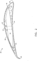
Fig. 2 is a cross-sectional view of an exemplary fan blade airfoil. -
Fig. 3 is a cross-sectional view of an alternative exemplary fan blade airfoil -
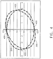
Fig. 4 depicts a graph showing two ellipses. -
Fig. 5 depicts a portion of the graph ofFig. 4 . -
Fig. 6 is side view of an exemplary winglet fan blade modification -
Fig. 7 is a cross-sectional view of the winglet ofFig. 6 . -
Fig. 8 is a top view of the winglet ofFig. 6 . -
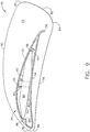
Fig. 9 is an end view of the fan blade ofFig. 2 modified with the winglet ofFig. 6 . -
Fig. 10 is an exploded perspective view of the winglet-blade assembly ofFig. 9 . - Reference will now be made in detail to the present preferred embodiment of the invention, an example of which is illustrated in the accompanying drawings.
- Referring now to the drawings in detail, wherein like numerals indicate the same elements throughout the views,
Fig. 1 showsexemplary fan hub 10, which may be used to provide a fan havingfan blades fan hub 10 includes a plurality ofhub mounting members 12 to whichfan blades fan hub 10 is coupled to a driving mechanism for rotatingfan hub 10 at selectable or predetermined speeds. A suitable hub assembly may thus comprisehub 10 and a driving mechanism coupled tohub 10. Of course, a hub assembly may include a variety of other elements, including a different hub, andfan hub 10 may be driven by any suitable means. In addition,fan hub 10 may have any suitable number ofhub mounting members 12. - As shown in
Figs. 1 through 3 , eachhub mounting member 12 has top surface 14 andbottom surface 16, which terminate into leadingedge 18 andtrailing edge 20. In addition, eachhub mounting member 12 includes opening 22 formed through top surface 14 and going throughbottom surface 16. In the present example, opening 22 is sized to receivefastener 26. Eachhub mounting member 12 is configured to receivefan blade hub mounting members 12 may be provided in a variety of alternative configurations. - In one embodiment,
fan blades U.S. Patent No. 6,244,821 . Of course,fan blades hub 10 at any suitable angular speed. By way of example only, such angular speed may be anywhere in the range of approximately 7 and 108 revolutions per minute. -
Fig. 2 shows a cross section ofexemplary fan blade 30 having curledtrailing edge 38, mounted tohub 10. The cross section is taken along a transverse plane located at the center offan blade 30, looking towardhub 10.Fan blade 30 hastop surface 32 andbottom surface 34, each of which terminate into leadingedge 36 andtrailing edge 38. As shown,trailing edge 38 has a slope of approximately 45° relative to portion oftop surface 32 that is proximate to trailingedge 38 and portion ofbottom surface 34 that is proximate to trailingedge 38. Of course,trailing edge 38 may have any other suitable slope, such as 0° by way of example only, to the extent that it comprises a single, flat surface. Other suitable trailingedge 38 configurations will be apparent to those of ordinary skill in the art. - In the present example,
fan blade 30 is substantially hollow. A plurality of ribs orbosses 40 are located insidefan blade 30. As shown, whenhub mounting member 12 is inserted intofan blade 30, ribs orbosses 40 are positioned such that they contact top surface 14,bottom surface 16, leadingedge 18, and trailingedge 20 ofhub mounting member 12. Bosses 40 thus provide a snug fit betweenfan blade 30 andhub mounting member 12. Alternative configurations forfan blade 30, including but not limited to those affecting the relationship between fan blade (30) and hub mounting member (12), will be apparent to those of ordinary skill in the art. - As used herein, terms such as "chord", "chord length", "maximum thickness," maximum camber," "angle of attack," and the like, shall be ascribed the same meaning ascribed to those terms as used in the art of airplane wing or other airfoil design. In one embodiment, fan blade (30) has a chord length of approximately 10 cm (6.4 inches). Fan blade (30) has a maximum thickness of approximately 16.2% of the chord; and a maximum camber of approximately 12.7% of the chord. The radius of leading edge (36) is approximately 3.9% of the chord. The radius of trailing edge (38) quadrant of bottom surface (34) is approximately 6.8% the chord. In an alternate embodiment, fan blade (30) has a chord of approximately 18 cm (7 inches). In another embodiment, fan blade (3) has a chord of approximately 17 cm (6.6875 inches). Of course, any other suitable dimensions and/or proportions may be used.
- By way of example only, fan blade (30) may display lift to drag ratios ranging from approximately 39.8, under conditions where the Reynolds Number is approximately 120,000, to approximately 93.3, where the Reynolds Number is approximately 250,000. Of course, other lift to drag ratios may be obtained with fan blade (30).
- In one embodiment, fan blade (30) displays drag coefficients ranging from approximately 0.027, under conditions where the Reynolds Number is approximately 75,000, to approximately 0.127, where the Reynolds Number is approximately 112,500. Of course, other drag coefficients may be obtained with fan blade (30).
- In one example, under conditions where the Reynolds Number is approximately 200,000, fan blade (30) moves air such that there is a velocity ratio of approximately 1.6 at bottom surface (34) at trailing edge (38) of fan blade (30). Other velocity ratios may be obtained with fan blade (30).
- In one embodiment, fan blade (30) provides non-stall aerodynamics for angles of attack between approximately -1° to 7°, under conditions where the Reynolds Number is approximately 112,000; and angles of attack between approximately -2° to 10°, where the Reynolds number is approximately 250,000. Of course, these values are merely exemplary.
-
Fig. 3 shows a cross section of another exemplary fan blade (50) having generally elliptical top surface (52) and bottom surface (54), each of which terminate in leading edge (56) and trailing edge (58), mounted to hub (10). The cross section is taken along a transverse plane located at the center of fan blade (50), looking toward hub (10). In the present example, fan blade (50) is hollow. A plurality of bosses (60) are located inside fan blade (50). As shown, when hub mounting member (12) is inserted into fan blade (50), bosses (60) are positioned such that they contact top surface (14), bottom surface (16), leading edge (18), and trailing edge (20) of hub mounting member (12). Bosses (60) thus provide a snug fit between fan blade (50) and hub mounting member (12). Alternative configurations for fan blade (50), including but not limited to those affecting the relationship between fan blade (50) and hub mounting member (12), will be apparent to those of ordinary skill in the art. - As shown, fan blade (50) has a lower radius of curvature toward its leading edge (56), as compared to a higher radius of curvature toward its trailing edge (58). The curvatures of fan blade (50) may be obtained, at least in part, through the generation of two ellipses using the following formulae. Those of ordinary skill in the art will appreciate that a first ellipse, with its origin at the intersection of Cartesian x and y axes, may be generated by these equations:


- where
- a = length of primary radius,
- b = length of secondary radius, and
- t = angle of rotation of a radius about the origin (e.g., in radians).
- Accordingly, a first ellipse may be generated using the foregoing equations. Similarly, a set of coordinates for the first ellipse may be obtained using equations [1] and [2]. Exemplary first ellipse (200) is illustrated in the graph depicted in
Fig. 4 , where a = 3 and b = 2. - Coordinates for a second ellipse may be obtained using these equations:


- where
- x2 = the second "x" coordinate after a counterclockwise rotation of the first ellipse through θ radians about the origin, and
- y2 = the second "y" coordinate after a counterclockwise rotation of the first ellipse through θ radians about the origin.
- Thus, the dimensions of the second ellipse are dependent on the dimensions of the first ellipse. Exemplary second ellipse (300) is illustrated in the graph depicted in
Fig. 4 , where θ = 0.525 radians. It will be appreciated that, where a first and second ellipse are plotted in accordance with equations [1] through [4], the two ellipses may intersect at four points ("ellipse intersections").Fig. 4 shows four ellipse intersections (400) between first ellipse (200) and second ellipse (300). - The curvature of top surface (52) and bottom surface (54) may be based, at least in part, on the curvature of the first and second ellipses between two consecutive ellipse intersections. An example of such a segment of first ellipse (200) and second ellipse (300) is shown in
Fig. 5 , which depicts the portion of ellipses (200 and 300) between consecutive ellipse intersections (400). Accordingly, equations [1] through [4] may be used to generate surface coordinates for at least a portion of top surface (52) and bottom surface (54) of fan blade (50). - It will be appreciated that the chord length-to-thickness ratio of fan blade (50) may vary with the amount of rotation, θ, relative the two ellipses.
- Of course, portions of fan blade (50) may deviate from the curvature of the first and second ellipses. By way of example only, and as shown in
Fig. 3 , leading edge (56) may be modified to have a generally circular curvature. Other deviations will be apparent to those of ordinary skill in the art. - In one embodiment, fan blade (50) is created using equations [1] through [4] with a = 3 units, b = 2 units, and θ = 0.525 radians. In this embodiment, fan blade (50) is fit with circular leading edge (56) having a diameter of 3.5% of chord length. This leading (56) edge curvature is fit tangentially to that of top surface (52) and bottom surface (54). Such a fit may be envisioned by comparing
Figs. 3 and5 . Of course, other dimensions may be used. - In one embodiment, fan blade (50) has a chord length of approximately 19 cm (7.67 inches). In another embodiment , fan blade has a chord length of approximately 20cm (7.687 inches). Of course, fan blade (50) may have any other suitable chord length.
- In the present example, the radius of leading edge (56) is approximately 3.5% of the chord. The maximum thickness of fan blade (50) is approximately 14.2% of the chord. The maximum camber of fan blade (50) is approximately 15.6% of the chord. Of course, any other suitable dimensions and/or proportions may be used.
- in one example, a fan having a 7 m (24-foot) diameter and comprising ten fan blades (50) mounted at an angle of attack of 10° produces a thrust force of approximately 2.4 kg (5.2 lb). When rotating at approximately 7 revolutions per minute (rpm), displacing approximately 2500 m3 per minute (87,302 cubic feet per minute (cfm)). When rotating at approximately 14 rpm, the fan produces a thrust force of approximately 4.8kg (10.52) lb)., displacing approximately 3500 m3 per minute (124,174 cfm). When rotating at approximately 42 rpm, the fan produces a thrust force of approximately 32.2kg (71.01 lb)., displacing approximately 9100 m3 per minute (322,613 cfm). Other thrust forces and/or displacement volumes may be obtained with a fan having fan blades (50).
- By way of example only, fan blade (50) having an angle of attack of approximately 10° may display lift to drag ratios ranging from approximately 39, under conditions where the Reynolds Number is approximately 120,000, to approximately 60, where the Reynolds Number is approximately 250,000. Other lift to drag ratios may be obtained with fan blade (50).
- In one embodiment, fan blade (50) provides non-stall aerodynamics for angles of attack between approximately 1° to 11°, under conditions where the Reynolds Number is approximately 112,000; for angles of attack between approximately 0° and 13°, where the Reynolds number is approximately 200,000; and for angles of attack between approximately 1° to 13°, where the Reynolds number is approximately 250,000. Of course, these values are merely exemplary.
- In one example, a fan having a 4m (14-foot) diameter and comprising ten fan blades (50) is rotated at approximately 25 rpm. The fan runs at approximately 54 watts, with a torque of approximately 8.9NM (78.80 inch-pounds (in.lbs.)) and a flow rate of approximately 970m3 per minute (34,169 cfm). The fan thus has an efficiency of approximately 18m3/per minute/watt (632.76 cfm/Watt).
- In another example, a fan having a 4m (14-foot) diameter and comprising ten fan blades (50) is rotated at approximately 37.5 rpm. The fan runs at approximately 82 watts, with a torque of approximately 21Nm (187.53) inch-pounds (in.lbs)) and a flow rate of approximately 800 m3 per minute (62,421 cfm). The fan thus has an efficiency of approximately 22 m3 per minute/watt (761.23 cfm/watt).
- In yet another example, a fan having a 4m (14-foot) diameter and comprising ten fan blades (50) is rotated at approximately 50 rpm. The fan runs at approximately 263 watts, with a torque of approximately 43Nm (376.59 inch-pounds (in.lbs)) and a flow rate of approximately 2700 m3 per minute (96,816 cfm). The fan thus has an efficiency of approximately 10 m3 per minute/watt (368.12 cfm/watt).
- The following may be applied to any fan blade, including by way of example only, fan blade (30) or fan blade (50):
- In one embodiment, each fan blade (30 or 50) comprises a homogenous continuum of material. By way of example only, fan blades (30 and 50) may be constructed of extruded aluminum. However, it will be appreciated that fan blades (30 and/or 50) may be constructed of any other suitable material or materials, including but not limited to any metal and/or plastic. In addition, it will be appreciated that fan blades (30 and/or 50) may be made by any suitable method of manufacture, including but not limited to stamping, bending, welding, and/or molding. Other suitable materials and methods of manufacture will be apparent to those of ordinary skill in the art.
- When fan blade (30 or 50) is mounted to hub (10), hub mounting members (12) may extend into fan blade (30 or 50) approximately 15cm (6 inches), by way of example only. Alternatively, hub mounting members (12) may extend into fan blade (30 or 50) to any suitable length. It will also be appreciated that hub (10) may have mounting members (12) that fit on the outside of fan blades (30 or 50), rather than inside. Alternatively, mounting members (12) may fit both partially inside and partially outside fan blades (30 or 50).
- Fan blade (30 or 50) may also include one or more openings configured to align with openings (22) in hub mounting member (12). In this embodiment, when openings in fan blade (30 or 50) are aligned with openings (22) is hub mounting member (12), fastener (26) may be inserted through the opening to secure fan blade (30 or 50) to hub mounting member (12). In one embodiment, fastener (26) is a bolt. Other suitable alternatives for fastener(s) (26) will be apparent to those of ordinary skill in the art, including but not limited to adhesives. Accordingly, it will be understood that openings (22) are optional.
- Fan blade (30 or 50) may be approximately 1.2, 1.4, 1.8, 2.1, 2.4, 2.7, 3.0, 3.4, 3.7, 4.0 or 4.2m (4, 5, 6, 7, 8, 9, 10, 11, 12, 13, or 14 feet) long. Alternatively, fan blade (30 ro 50) may be of any other suitable length. In one embodiment, fan blade (30 or 50) and hub (10) are sized such that a fan comprising fan blades (30 or 50) and hub (10) has a diameter of approximately 7m (24 feet). In another embodiment, fan blade (30 or 50) and hub (10) are sized such that a fan comprising fan blades (30 or 50) and hub (10) has a diameter of approximately 4m (14 feet).
- Other suitable dimensions will be apparent to those of ordinary skill in the art.
- It will be appreciated that all cross sections along the length of fan blade (30 or 50) need not be identical. In other words, the configuration of fan blade (30 or 50) need not be uniform along the entire length of fan blade (30 or 50). By way of example only, a portion of the "hub mounting end" of fan blade (30 or 50) (i.e. the end of fan blade (30 or 50) that will be mounted to hub (10)) may be removed. In one example, an oblique cut is made to leading edge (56) of fan blade (50) to accommodate another blade (50) on hub (10).
- Alternatively, fan blade (30 or 50) may be formed or constructed such that a portion of the hub mounting end or another portion is omitted, relieved, or otherwise "missing." It will be appreciated that the absence of such a portion (regardless of whether it was removed or never there to begin with) may alleviate problems associated with blades (30 or 50) interfering with each other at hub (10). Such interference may be caused by a variety of factors, including but not limited to chord length of fan blades (30 or 50). Of course, factors other than interference may influence the removal or other absence of a portion of fan blade (30 or 50). The absent portion may comprise a portion of leading edge (36 or 56), a portion of trailing edge (38 or 58), or both.
- Alternatively, to address fan blade (30 or 50) interference at hub (10), the diameter of hub may be increased (e.g., such as without increasing the number of hub mounting members (12)). Alternatively, the chord of fan blades (30 or 50) may be reduced. Still other alternatives and variations of hub (10) and/or fan blades (30 or 50) will be apparent to those of ordinary skill in the art.
- Those of ordinary skill in the art will appreciate that fan blade (30 or 50) may have a zero or non-zero angle of attack. By way of example only, when mounted to hub mounting member (12), fan blade (30 or 50) may have an angle of attack in the range of approximately -1 to 7°, inclusive; between -2° and 10°, inclusive; or approximately 7°, 8°, 10°, or 13° by way of example only. Of course, fan blade (30 or 50) may have any other suitable angle of attack. Fan blade (30 or 50) may be substantially straight along its length, and the angle of attack may be provided by having hub mounting member (12) with the desired angle of attack.
- Alternatively, the angle of attack of hub mounting member (12) may be zero, and an angle of attack for fan blade (30 or 50) may be provided by a twist in fan blade (30 or 50). In other words, fan blade (30 or 50) may be substantially straight along the length to which hub mounting member (12) extends in fan blade (30 or 50), and a twist may be provided to provide an angle of attack for the remaining portion of fan blade (30 or 50). Such a twist may occur over any suitable length of fan blade (30 or 50) (e.g. the entire remainder of fan blade (30 or 50) length has a twist; or the twist is brief, such that nearly all of the remainder of fan blade (30 or 50) is substantially straight; etc.). Still other suitable configurations and methods for providing an angle of attack for all or part of fan blade (30) will be apparent to those of ordinary skill in the art. In addition, it will be appreciated that all or any portion of fan blade (30 or 50) may have one or more twists for any purpose.
- Those of ordinary skill in the art will appreciate that a fan blade (e.g., 30 or 50) may be modified in a number of ways. Such modifications may alter the characteristics of fan performance. As illustrated in exemplary form in
Figs. 6 through 10 , one such modification may include winglet (70). While winglets (70) will be discussed in the context of fan blades (30 and 50), it will be appreciated that winglets (70) may be used with any other suitable fan blades. - Winglet (70) of the present example includes vertical member (72). Vertical member (72) comprises flat inner surface (74) and rounded outer surface (76). Other suitable configurations for inner surface (74) and outer surface (76) will be apparent to those of ordinary skill in the art. In the present example, the perimeter of vertical member (72) is defined by lower edge (78), upper edge (80), and rear edge (82). Each edge (78, 80, and 82) meets generally at respective corner (84). Thus, in the present example, vertical member (72) has three corners (84). As shown, each corner (84) is rounded. Accordingly, the term "corner," as that term is used herein, shall not be read to require a sharp angle. In other words, a corner need not be limited to a point or region at which a pair of straight lines meet or intersect. While in the present example vertical member (72) is described as having three corners, it will be appreciated that vertical member (72) may have any suitable number of corners (84).
- Other variations of vertical member (72) will be apparent to those of ordinary skill in the art.
- Winglet (70) of the present example further includes winglet mounting member (90), which extends substantially perpendicularly from inner surface (74) of vertical member (72). As shown, winglet mounting member (90) is configured similar to hub mounting member (12). Winglet mounting member (90) has top surface (92) and bottom surface (94), which each terminate into leading edge (96) and trailing edge (98). In addition, each winglet mounting member (92) includes openings (100) formed through top surface (92) and bottom surface (94). In the present example, each opening (100) is sized to receive fastener (26). Winglet mounting member (90) is configured to be inserted into an end of fan blade (30 or 50). Those of ordinary skill in the art will appreciate that winglet mounting members (90) may be provided in a variety of alternative configurations.
-
Fig. 9 shows a cross section of fan blade (30) with winglet (70) mounted thereto. The cross section is taken along a transverse plane located at the center of fan blade (30), looking toward winglet (70) (i.e. away from hub (10)). In the present example, and as shown inFigs. 9 and10 , winglet mounting member (90) is configured to fit in the end of fan blade (30 or 50). Like hub mounting member (12), winglet mounting member (90) fits snugly against bosses (40 or 60) in fan blade (30 or 50). In the present example, upper edge (80) of winglet (70) extends above top surface (32 or 52) of fan blade (30 or 50), in addition to extending beyond leading edge (36 or 56). Similarly, lower edge (78) of winglet (70) extends below bottom surface (34 or 54) of fan blade (30 or 50). Rear edge (82) of winglet (70) extends beyond trailing edge (38 or 58) of fan blade (30 or 50). Of course, winglets (70) and fan blades (30 or 50) may have any other relative sizing and/or configuration. - Fan blade (30 or 50) may have one or more openings, formed near the tip of fan blade (30 or 50) through top surface (32 or 52) and/or bottom surface (34 or 54), which is/are positioned to align with opening(s) (100) in winglet mounting member (90) when winglet mounting member (90) is inserted into fan blade (30 or 50), and which is/are sized to receive fastener (26). Winglets (70) may thus be secured to fan blades (30 or 50) with one or more fasteners (26). In one embodiment, fastener (26) is a bolt. In another embodiment, fastener (26) comprises a complimentary pair of thin head interlocking binding screws, such as screw posts occasionally used to bind a large volume of papers together (e.g., "male" screw with threaded outer surface configured to mate with "female" screw having threaded inner surface). However, any other suitable fastener(s) may be used, including but not limited to adhesives. Accordingly, it will be appreciated that openings (100) are optional.
- It will also be appreciated that winglet mounting member (90) need not be inserted into an end of fan blade (30 or 50). In other words, and similar to hub mounting members (12), winglet mounting member (90) may be made to fit on the outside of fan blades (30 or 50), rather than inside. Alternatively, winglet mounting members (90) may fit both partially inside and partially outside fan blades (30 or 50). Still other configurations will be apparent to those of ordinary skill in the art.
- In an alternate embodiment, winglet (70) lacks mounting member (90), and instead has a recess formed in inner surface (74) of vertical member (72). In this embodiment, the tip of fan blade (30 or 50) is inserted into winglet (70) for attachment of winglet (70) to fan blade (30 or 50). In yet another embodiment, fan blade (30 or 50) is integrally formed with winglet (70). Accordingly, those of ordinary skill in the art will appreciate that there exists a variety of configurations for providing fan blade (30 or 50) with winglet (70).
- While vertical member (72) is shown as being substantially perpendicular to mounting member (90), it will be appreciated that these two members may be at any suitable angle relative to each other. Thus, and by way of example only, vertical member (72) may tilt inward or outward when winglet (70) is attached to fan blade (30 or 50). Alternatively, vertical member (72) may comprise more than one angle. In other words, vertical member (72) may be configured such that the top portion of vertical member and the bottom portion of vertical member each tilt inward when winglet is attached to fan blade (30 or 50). Other variations of winglet (70), including but not limited to angular variations, will be apparent to those of ordinary skill in the art.
- While winglet (70) is specifically described herein as a modification to fan blades (30 or 50), it will be appreciated that winglet (70) may be used to modify any other fan blades.
- In one embodiment, winglet (70) is formed from homogenous continuum of molded plastic. However, it will be appreciated that winglet (70) may be made from a variety of materials, including but not limited to any suitable metal and/or plastic, and may comprise a plurality of pieces. In addition, it will be appreciated that winglet may be made by any suitable method of manufacture.
- It will also be appreciated that trailing vortices that form at or near the tips of fan blades (30 or 50) may increase lift near the tips of fan blades (30 or 50). Winglets (70) may inhibit the radial airflow over top surface (32 or 52) and/or bottom surface (34 or 54) near the tips of fan blades (30 or 50). Such inhibition may force air to flow more normally from leading edge (36 or 56) to trailing edge (38 or 58), thereby enhancing efficiency of a fan having fan blades (30 or 50) with winglets (70), at least at certain rotational speeds.
- In one example, winglets (70) are attached to ends of fan blades (30 or 50) on a fan having a 2m (6 foot) diameter. With the addition of winglets (70), the air flow rate of the fan is increased by 4.8% at 171 rpm.
- In another example, winglets (70) are attached to ends of fan blades (30 or 50) on a fan having a 4m (14 foot) diameter. With the addition of winglets (70), the air flow rate of the fan is increased by 4.4% at 75 rpm
- The following two tables illustrate efficiencies that may be obtained by adding winglets (70) to a fan having a 4m (14 foot) diameter:
Table 1: Fan Without Winglets (70) Speed (rpm) Max. Power (watt) Avg. Power (watt) Torque (Nm) Flowrate (m3 per minute) Efficiency (m3 per minute/watt) 12.5 54 50 2.0 (17.86 in.lbs) 0 (0 cfm) 0 (0 cfm/watt) 25 66 54 8.9 (78.80 in.lbs) 970 (34,169 cfm) 18 (632.76 cfm/watt) 37.5 125 82 21 (187.53 in.lbs) 1800 (62,421 cfm) 22 (761.23 cfm/watt) 50 339 263 43 (376.59 in.lbs) 2700 (96,816 cfm) 10(368.12 cfm/watt) 62.5 700 660 64 (564.01 in.lbs) 3100 (110,784 cfm) 0.5 (167.85 cfm/watt) 75 1170 1140 95 (839.75 in.lbs) 3700 (129,983 cfm) 0.4(114.02 cfm/watt) Table 2: Fan With Winglets (70) Speed (rpm) Max. Power (watt) Avg. Power (watt) Torque (Nm) Flowrate (m3 per minute) Efficiency (m3 per minute/watt) 12.5 50 42 2.0 (18.56 in. lbs) 760 (26,815 cfm) 18 (638.45 cfm/watt) 25 58 43 8.9 (18.39 in.lbs) 1300 (46,547 cfm) 31 (1,082.49 cfm/watt) 37.5 68 49 21 (186.00 in.lbs) 1700 (61,661 cfm) 36 (1,258.39 cfm/watt) 50 241 198 43 (354.61 in.lbs) 2500 (87,552 cfm) 13 (442.18 cfm/watt) 62.5 591 528 64 (582.78 in.lbs) 3400 (120,859 cfm) 6 (228.90 cfm/watt) 75 980 950 95 (847.41 in.lbs) 3900 (136,560 cfm) 4 (143.75 cfm/watt) - Of course, other values may be realized through use of winglets (70). In addition, suitable variations of winglets, including but not limited to alternative winglet configurations, will be apparent to those of ordinary skill in the art.
- In summary, numerous benefits have been described which result from employing the concepts of the invention. The foregoing description of one or more embodiments of the invention has been presented for purposes of illustration and description. It is not intended to be exhaustive or to limit the invention to the precise form disclosed. Obvious modifications or variations are possible in light of the above teachings. The one or more embodiments were chosen and described in order to best illustrate the principles of the invention and its practical application to thereby enable one of ordinary skill in the art to best utilize the invention in various embodiments and with various modifications as are suited to the particular use contemplated. It is intended that the scope of the invention be defined by the claims appended hereto.
Claims (10)
- A fan blade (50) configured to mount to a rotating fan hub (10), the fan blade (50) comprising:(a) a top surface (52) having a generally elliptical curvature;(b) a bottom surface (54) having a generally elliptical curvature;(c) a leading edge (56), wherein the top surface (52) and bottom surface (54) each terminate at the leading edge (56); and(d) a trailing edge (58), wherein the top surface (52) and bottom surface (54) each terminate at the trailing edge (58);
characterized in that:the curvature of the top surface (52) is based on a first ellipse (200) having a first primary radius and a first secondary radius;the curvature of the bottom surface (54) is based on a second ellipse (300) having a second primary radius and a second secondary radius; andwherein the first primary radius and the first secondary radius are not equal. - The fan blade of claim 1, further comprising: a first radius of curvature proximate the leading edge (56), and a second radius of curvature proximate the trailing edge (58), wherein the first radius of curvature is lower than the second radius of curvature.
- The fan blade of claim 1, wherein the curvature of the second ellipse (300) is dependent on the curvature of the first ellipse (200).
- The fan blade of claim 1, wherein the first ellipse (200) is generated based at least in part on the following equations:

 wherein x and y provide an x-y plot of the first ellipse (200),wherein a = length of the first primary radius,wherein b = length of the first secondary radius, andwherein t = angle of rotation of a radius about an origin.
 - The fan blade of claim 4, wherein the second ellipse (300) is generated based at least in part on the following equations:

 x2 and y2 provide an x-y plot of the second ellipse (300), andwherein θ = an angle of rotation of the first ellipse about the origin.
 - The fan blade of claim 5, wherein θ = 0.525 radians.
- The fan blade of claim 1, wherein the cross section of the fan blade (50) is uniform along the length of the fan blade (50).
- The fan blade of claim 1, wherein the fan blade (50) is substantially straight along the length of the fan blade (50).
- The fan blade of claim 1, wherein the fan blade (50) is substantially hollow.
- The fan blade of claim 1, wherein the fan blade (50) is formed of extruded aluminum.
Applications Claiming Priority (2)
| Application Number | Priority Date | Filing Date | Title |
|---|---|---|---|
| US58994504P | 2004-07-21 | 2004-07-21 | |
| US11/046,593 US7284960B2 (en) | 2004-07-21 | 2005-01-28 | Fan blades |
Publications (3)
| Publication Number | Publication Date |
|---|---|
| EP1619392A2 EP1619392A2 (en) | 2006-01-25 |
| EP1619392A3 EP1619392A3 (en) | 2006-09-20 |
| EP1619392B1 true EP1619392B1 (en) | 2017-01-04 |
Family
ID=35355209
Family Applications (1)
| Application Number | Title | Priority Date | Filing Date |
|---|---|---|---|
| EP05250654.0A Expired - Lifetime EP1619392B1 (en) | 2004-07-21 | 2005-02-04 | Fan blades |
Country Status (3)
| Country | Link |
|---|---|
| US (1) | US7284960B2 (en) |
| EP (1) | EP1619392B1 (en) |
| ES (1) | ES2631252T3 (en) |
Cited By (17)
| Publication number | Priority date | Publication date | Assignee | Title |
|---|---|---|---|---|
| USD880684S1 (en) | 2018-07-10 | 2020-04-07 | Hunter Fan Company | Ceiling fan blade |
| USD880681S1 (en) | 2018-07-10 | 2020-04-07 | Hunter Fan Company | Ceiling fan blade |
| USD880680S1 (en) | 2018-07-10 | 2020-04-07 | Hunter Fan Company | Ceiling fan blade |
| USD880683S1 (en) | 2018-07-10 | 2020-04-07 | Hunter Fan Company | Ceiling fan blade |
| USD880682S1 (en) | 2018-07-10 | 2020-04-07 | Hunter Fan Company | Ceiling fan blade |
| USD902377S1 (en) | 2018-07-10 | 2020-11-17 | Hunter Fan Company | Ceiling fan blade |
| USD903092S1 (en) | 2018-07-10 | 2020-11-24 | Hunter Fan Company | Ceiling fan blade |
| USD903091S1 (en) | 2018-07-10 | 2020-11-24 | Hunter Fan Company | Ceiling fan blade |
| USD905227S1 (en) | 2018-07-10 | 2020-12-15 | Hunter Fan Company | Ceiling fan blade |
| USD905226S1 (en) | 2018-07-10 | 2020-12-15 | Hunter Fan Company | Ceiling fan blade |
| USD905845S1 (en) | 2018-07-10 | 2020-12-22 | Hunter Fan Company | Ceiling fan blade |
| USD906511S1 (en) | 2018-07-10 | 2020-12-29 | Hunter Fan Company | Ceiling fan blade |
| US11111930B2 (en) | 2018-07-10 | 2021-09-07 | Hunter Fan Company | Ceiling fan blade |
| USD957618S1 (en) | 2018-07-10 | 2022-07-12 | Hunter Fan Compnay | Ceiling fan blade |
| USD957619S1 (en) | 2018-07-10 | 2022-07-12 | Hunter Fan Company | Ceiling fan blade |
| USD957617S1 (en) | 2018-07-10 | 2022-07-12 | Hunter Fan Company | Ceiling fan blade |
| USD980408S1 (en) | 2018-07-10 | 2023-03-07 | Hunter Fan Company | Ceiling fan blade |
Families Citing this family (61)
| Publication number | Priority date | Publication date | Assignee | Title |
|---|---|---|---|---|
| US7934907B2 (en) * | 2004-07-21 | 2011-05-03 | Delta T Corporation | Cuffed fan blade modifications |
| US8079823B2 (en) * | 2004-07-21 | 2011-12-20 | Delta T Corporation | Fan blades |
| US7252478B2 (en) * | 2004-07-21 | 2007-08-07 | Delta T Corporation | Fan blade modifications |
| ES2319599B1 (en) * | 2007-01-08 | 2010-01-26 | Guillermo Petri Larrea | REVERSIBLE SECTIONING SYSTEM IN VARIOUS PARTS OF AEROGENERATING BLADES. |
| EP2118494B1 (en) * | 2007-03-01 | 2019-05-01 | Delta T, LLC | Angled airfoil extension for fan blade |
| US20080253896A1 (en) * | 2007-04-13 | 2008-10-16 | Walls Gary C | High efficiency fan blades with airflow-directing baffle elements |
| NL2000667C2 (en) * | 2007-05-29 | 2008-12-02 | Herman Ter Wijlen | Fan system. |
| US8152453B2 (en) * | 2007-09-17 | 2012-04-10 | Delta T Corporation | Ceiling fan with angled mounting |
| US8147204B2 (en) * | 2007-09-26 | 2012-04-03 | Delta T Corporation | Aerodynamic interface component for fan blade |
| US8672649B2 (en) * | 2007-10-10 | 2014-03-18 | Delta T Corporation | Ceiling fan system with brushless motor |
| WO2009049052A1 (en) * | 2007-10-10 | 2009-04-16 | Delta T Corporation | Ceiling fan with concentric stationary tube and power-down features |
| US8123479B2 (en) * | 2007-12-19 | 2012-02-28 | Delta T Corporation | Method to minimize oscillation in ceiling fans |
| ES2733595T3 (en) * | 2008-02-04 | 2019-12-02 | Delta T Llc | Automatic control system for ceiling fan based on temperature and humidity differentials |
| CA2941957C (en) | 2008-03-06 | 2019-06-04 | Delta T Corporation | Ceiling fan with l-shaped blade retainers |
| USD587799S1 (en) | 2008-08-15 | 2009-03-03 | Delta T Corporation | Winglet for a fan blade |
| US20100054948A1 (en) * | 2008-09-04 | 2010-03-04 | Ken-Tuan Chen | Blades of a ceiling fan (2) |
| US20100054947A1 (en) * | 2008-09-04 | 2010-03-04 | Ken-Tuan Chen | Blades of a ceiling fan (1) |
| WO2010053775A1 (en) * | 2008-10-29 | 2010-05-14 | Delta T Corporation | Multi-part modular airfoil section and method of attachment between parts |
| WO2010111339A1 (en) * | 2009-03-25 | 2010-09-30 | Delta T Corporation | High efficiency ducted fan |
| AU2010246122B2 (en) * | 2009-05-04 | 2015-06-18 | Aspen Motion Technologies, Inc | Ceiling fan with variable blade pitch and variable speed control |
| SG179003A1 (en) * | 2009-10-02 | 2012-04-27 | Delta T Corp | Air fence for fan blade |
| USD635237S1 (en) | 2010-03-05 | 2011-03-29 | Delta T Corporation | Fan with ground support |
| USD641075S1 (en) | 2010-03-05 | 2011-07-05 | Delta T Corporation | Fan with ground support and winglets |
| US8770937B2 (en) | 2010-04-22 | 2014-07-08 | Delta T Corporation | Fan blade retention system |
| US8562302B2 (en) * | 2010-07-06 | 2013-10-22 | General Electric Company | Wind turbine blade with integrated handling mechanism attachment bores |
| CA2861920C (en) | 2012-01-20 | 2022-10-18 | Delta T Corporation | Thin airfoil ceiling fan blade |
| IN2014DN06523A (en) | 2012-01-25 | 2015-06-12 | Delta T Corp | |
| USD672868S1 (en) | 2012-02-09 | 2012-12-18 | Delta T Corporation | Winglet for fan blade |
| WO2013152014A1 (en) * | 2012-04-03 | 2013-10-10 | Delta T Corporation | Airfoil for fan blade |
| US9011099B2 (en) | 2012-06-19 | 2015-04-21 | Skyblade Fan Company | High volume low speed fan |
| US8842000B2 (en) | 2012-07-17 | 2014-09-23 | 4Front Engineered Solutions, Inc. | Fire control systems |
| US9121287B2 (en) | 2012-09-12 | 2015-09-01 | United Technologies Corporation | Hollow fan blade with honeycomb filler |
| CA2902863C (en) | 2012-10-31 | 2023-09-12 | Delta T Corporation | Integrated thermal comfort control system utilizing circulating fans |
| US10309663B1 (en) | 2013-03-15 | 2019-06-04 | Delta T, Llc | Condensation control system and related method |
| USD723678S1 (en) | 2013-06-17 | 2015-03-03 | Delta T Corporation | Winglet for a ceiling fan |
| US9874214B2 (en) | 2014-01-28 | 2018-01-23 | 4Front Engineered Solutions, Inc. | Fan with fan blade mounting structure |
| USD732657S1 (en) | 2014-02-27 | 2015-06-23 | Delta T Corporation | Winglet |
| USD717936S1 (en) | 2014-02-27 | 2014-11-18 | Delta T Corporation | Blade tip |
| US9856883B1 (en) | 2014-04-14 | 2018-01-02 | Delta T Corporation | Predictive condensation control system and related method |
| US11085455B1 (en) * | 2014-08-11 | 2021-08-10 | Delta T, Llc | System for regulating airflow associated with product for sale |
| US9726192B2 (en) | 2015-03-31 | 2017-08-08 | Assa Abloy Entrance Systems Ab | Fan blades and associated blade tips |
| US20170159664A1 (en) * | 2015-12-08 | 2017-06-08 | Phase Industrial Design Ningbo Co., Ltd. | Direct Drive Ceiling Fan |
| US11674526B2 (en) | 2016-01-22 | 2023-06-13 | Hunter Fan Company | Ceiling fan having a dual redundant motor mounting assembly |
| EP4030064B1 (en) | 2015-12-14 | 2024-08-14 | Hunter Fan Company | Ceiling fan |
| CN107542684B (en) | 2016-06-28 | 2020-05-05 | 建准电机工业股份有限公司 | ceiling fan |
| TWI617743B (en) * | 2016-06-28 | 2018-03-11 | 建準電機工業股份有限公司 | Ceiling fan |
| CN106050739A (en) * | 2016-07-22 | 2016-10-26 | 西安航空制动科技有限公司 | High-performance wing section for cooling fan |
| CN106523431B (en) * | 2016-12-09 | 2019-06-11 | 长沙福田汽车科技有限公司 | Blade, fan and spray device having the same, and method for determining blade |
| US11359643B2 (en) | 2017-03-20 | 2022-06-14 | Shop Vac Corporation | Fan having housing formed by connectable pieces and including air guide ribs and an internal ramp |
| TWI655369B (en) * | 2018-01-11 | 2019-04-01 | 建準電機工業股份有限公司 | ceiling fan |
| US11175081B1 (en) | 2018-04-27 | 2021-11-16 | Delta T, Llc | Condensation control system with radiant heating and related method |
| US11480191B2 (en) | 2019-09-24 | 2022-10-25 | Delta T, Llc | Blade retention system for overhead fan |
| IT202000005110A1 (en) * | 2020-03-10 | 2021-09-10 | Cofimco Srl | BLADE SYSTEM FOR FANS FOR INDUSTRIAL USE |
| US20210388841A1 (en) | 2020-06-16 | 2021-12-16 | Delta T, Llc | Ceiling fan with germicidal capabilities |
| US12383651B2 (en) | 2020-10-30 | 2025-08-12 | Nordicco ApS | Fan assembly with ultra violet disinfection |
| CN114673685B (en) * | 2020-12-25 | 2024-07-12 | 广东美的白色家电技术创新中心有限公司 | Fan blade profile construction method, fan blade, fan equipment and storage medium |
| US12331753B2 (en) | 2021-06-28 | 2025-06-17 | Nordicco A/S | Blade construction |
| US20250389278A1 (en) * | 2022-02-28 | 2025-12-25 | Delta T, Llc | Fan blades and modifications thereof |
| WO2023197869A1 (en) * | 2022-04-13 | 2023-10-19 | 苏州欧普照明有限公司 | Blade structure and fan lamp |
| CN122148592A (en) * | 2022-04-13 | 2026-06-05 | 欧普照明股份有限公司 | Fan blade structure and fan lamp |
| WO2025165810A1 (en) | 2024-01-29 | 2025-08-07 | Delta T, Llc | Modular restrictor for a dynamic fan mount |
Citations (3)
| Publication number | Priority date | Publication date | Assignee | Title |
|---|---|---|---|---|
| US2592471A (en) * | 1946-08-22 | 1952-04-08 | James G Sawyer | Axial flow fan |
| EP0096255A1 (en) * | 1982-06-01 | 1983-12-21 | Siemens Aktiengesellschaft | Electric motor-driven axial fan, especially for motor vehicle cooling fans |
| JPH04234598A (en) * | 1990-12-29 | 1992-08-24 | Toshiba Corp | Multiblade fan |
Family Cites Families (15)
| Publication number | Priority date | Publication date | Assignee | Title |
|---|---|---|---|---|
| US572535A (en) * | 1896-12-08 | Type-writing machine | ||
| GB100134A (en) | 1915-03-01 | 1917-03-01 | Bbc Brown Boveri & Cie | Improvements in the Manufacture of Blades for Steam and Gas Turbines. |
| DE3017226A1 (en) | 1979-05-12 | 1980-11-20 | Papst Motoren Kg | FAN BLADE |
| US4968216A (en) * | 1984-10-12 | 1990-11-06 | The Boeing Company | Two-stage fluid driven turbine |
| DE3819145A1 (en) | 1988-06-04 | 1989-12-14 | Albrecht George Prof D Fischer | Aerodynamically active end plates for aircraft-wing and propeller-blade tips |
| US5823480A (en) * | 1993-04-05 | 1998-10-20 | La Roche; Ulrich | Wing with a wing grid as the end section |
| US5564901A (en) * | 1993-12-14 | 1996-10-15 | The Moore Company | Low noise fan |
| US6161797A (en) * | 1996-11-25 | 2000-12-19 | Dugan Air Technologies, Inc. | Method and apparatus for reducing airplane noise |
| US5725355A (en) | 1996-12-10 | 1998-03-10 | General Electric Company | Adhesive bonded fan blade |
| US6039541A (en) * | 1998-04-07 | 2000-03-21 | University Of Central Florida | High efficiency ceiling fan |
| US6884034B1 (en) * | 1998-04-07 | 2005-04-26 | University Of Central Florida | Enhancements to high efficiency ceiling fan |
| US6244821B1 (en) * | 1999-02-19 | 2001-06-12 | Mechanization Systems Company, Inc. | Low speed cooling fan |
| US6565320B1 (en) * | 2000-11-13 | 2003-05-20 | Borgwarner, Inc. | Molded cooling fan |
| US6626640B2 (en) * | 2001-11-19 | 2003-09-30 | Durmitor Inc. | Fan with reduced noise |
| US6719533B2 (en) * | 2002-07-11 | 2004-04-13 | Hunter Fan Company | High efficiency ceiling fan |
-
2005
- 2005-01-28 US US11/046,593 patent/US7284960B2/en not_active Expired - Lifetime
- 2005-02-04 ES ES05250654.0T patent/ES2631252T3/en not_active Expired - Lifetime
- 2005-02-04 EP EP05250654.0A patent/EP1619392B1/en not_active Expired - Lifetime
Patent Citations (3)
| Publication number | Priority date | Publication date | Assignee | Title |
|---|---|---|---|---|
| US2592471A (en) * | 1946-08-22 | 1952-04-08 | James G Sawyer | Axial flow fan |
| EP0096255A1 (en) * | 1982-06-01 | 1983-12-21 | Siemens Aktiengesellschaft | Electric motor-driven axial fan, especially for motor vehicle cooling fans |
| JPH04234598A (en) * | 1990-12-29 | 1992-08-24 | Toshiba Corp | Multiblade fan |
Cited By (19)
| Publication number | Priority date | Publication date | Assignee | Title |
|---|---|---|---|---|
| USD880684S1 (en) | 2018-07-10 | 2020-04-07 | Hunter Fan Company | Ceiling fan blade |
| USD880681S1 (en) | 2018-07-10 | 2020-04-07 | Hunter Fan Company | Ceiling fan blade |
| USD880680S1 (en) | 2018-07-10 | 2020-04-07 | Hunter Fan Company | Ceiling fan blade |
| USD880683S1 (en) | 2018-07-10 | 2020-04-07 | Hunter Fan Company | Ceiling fan blade |
| USD880682S1 (en) | 2018-07-10 | 2020-04-07 | Hunter Fan Company | Ceiling fan blade |
| USD902377S1 (en) | 2018-07-10 | 2020-11-17 | Hunter Fan Company | Ceiling fan blade |
| USD903092S1 (en) | 2018-07-10 | 2020-11-24 | Hunter Fan Company | Ceiling fan blade |
| USD903091S1 (en) | 2018-07-10 | 2020-11-24 | Hunter Fan Company | Ceiling fan blade |
| USD905227S1 (en) | 2018-07-10 | 2020-12-15 | Hunter Fan Company | Ceiling fan blade |
| USD905226S1 (en) | 2018-07-10 | 2020-12-15 | Hunter Fan Company | Ceiling fan blade |
| USD905845S1 (en) | 2018-07-10 | 2020-12-22 | Hunter Fan Company | Ceiling fan blade |
| USD906511S1 (en) | 2018-07-10 | 2020-12-29 | Hunter Fan Company | Ceiling fan blade |
| US11111930B2 (en) | 2018-07-10 | 2021-09-07 | Hunter Fan Company | Ceiling fan blade |
| USD957618S1 (en) | 2018-07-10 | 2022-07-12 | Hunter Fan Compnay | Ceiling fan blade |
| USD957619S1 (en) | 2018-07-10 | 2022-07-12 | Hunter Fan Company | Ceiling fan blade |
| USD957617S1 (en) | 2018-07-10 | 2022-07-12 | Hunter Fan Company | Ceiling fan blade |
| US11566633B2 (en) | 2018-07-10 | 2023-01-31 | Hunter Fan Company | Ceiling fan blade |
| USD980408S1 (en) | 2018-07-10 | 2023-03-07 | Hunter Fan Company | Ceiling fan blade |
| US11927196B2 (en) | 2018-07-10 | 2024-03-12 | Hunter Fan Company | Ceiling fan blade |
Also Published As
| Publication number | Publication date |
|---|---|
| US7284960B2 (en) | 2007-10-23 |
| EP1619392A3 (en) | 2006-09-20 |
| ES2631252T3 (en) | 2017-08-29 |
| US20060018758A1 (en) | 2006-01-26 |
| EP1619392A2 (en) | 2006-01-25 |
Similar Documents
| Publication | Publication Date | Title |
|---|---|---|
| EP1619391B1 (en) | Fan blade | |
| US7284960B2 (en) | Fan blades | |
| EP2195528B1 (en) | Cuffed fan blade modifications | |
| AU2010214764B2 (en) | Fan blades and modifications | |
| US8079823B2 (en) | Fan blades | |
| US20120128501A1 (en) | Fan blade tips | |
| CA2719755C (en) | Fan blades | |
| HK1086319B (en) | Fan blades | |
| HK1086319A (en) | Fan blades | |
| HK1086320A (en) | Fan blade | |
| HK1086320B (en) | Fan blade |
Legal Events
| Date | Code | Title | Description |
|---|---|---|---|
| PUAI | Public reference made under article 153(3) epc to a published international application that has entered the european phase |
Free format text: ORIGINAL CODE: 0009012 |
|
| AK | Designated contracting states |
Kind code of ref document: A2 Designated state(s): AT BE BG CH CY CZ DE DK EE ES FI FR GB GR HU IE IS IT LI LT LU MC NL PL PT RO SE SI SK TR |
|
| AX | Request for extension of the european patent |
Extension state: AL BA HR LV MK YU |
|
| PUAL | Search report despatched |
Free format text: ORIGINAL CODE: 0009013 |
|
| REG | Reference to a national code |
Ref country code: HK Ref legal event code: DE Ref document number: 1086319 Country of ref document: HK |
|
| AK | Designated contracting states |
Kind code of ref document: A3 Designated state(s): AT BE BG CH CY CZ DE DK EE ES FI FR GB GR HU IE IS IT LI LT LU MC NL PL PT RO SE SI SK TR |
|
| AX | Request for extension of the european patent |
Extension state: AL BA HR LV MK YU |
|
| 17P | Request for examination filed |
Effective date: 20070223 |
|
| AKX | Designation fees paid |
Designated state(s): AT BE BG CH CY CZ DE DK EE ES FI FR GB GR HU IE IS IT LI LT LU MC NL PL PT RO SE SI SK TR |
|
| 17Q | First examination report despatched |
Effective date: 20080107 |
|
| GRAP | Despatch of communication of intention to grant a patent |
Free format text: ORIGINAL CODE: EPIDOSNIGR1 |
|
| INTG | Intention to grant announced |
Effective date: 20160721 |
|
| GRAS | Grant fee paid |
Free format text: ORIGINAL CODE: EPIDOSNIGR3 |
|
| STAA | Information on the status of an ep patent application or granted ep patent |
Free format text: STATUS: GRANT OF PATENT IS INTENDED |
|
| GRAA | (expected) grant |
Free format text: ORIGINAL CODE: 0009210 |
|
| STAA | Information on the status of an ep patent application or granted ep patent |
Free format text: STATUS: THE PATENT HAS BEEN GRANTED |
|
| AK | Designated contracting states |
Kind code of ref document: B1 Designated state(s): AT BE BG CH CY CZ DE DK EE ES FI FR GB GR HU IE IS IT LI LT LU MC NL PL PT RO SE SI SK TR |
|
| REG | Reference to a national code |
Ref country code: GB Ref legal event code: FG4D |
|
| REG | Reference to a national code |
Ref country code: DE Ref legal event code: R081 Ref document number: 602005051054 Country of ref document: DE Owner name: DELTA T, LLC, LEXINGTON, US Free format text: FORMER OWNER: DELTA T CORP., LEXINGTON, KENTUCKY, US |
|
| REG | Reference to a national code |
Ref country code: CH Ref legal event code: EP |
|
| REG | Reference to a national code |
Ref country code: AT Ref legal event code: REF Ref document number: 859525 Country of ref document: AT Kind code of ref document: T Effective date: 20170115 |
|
| REG | Reference to a national code |
Ref country code: IE Ref legal event code: FG4D |
|
| REG | Reference to a national code |
Ref country code: DE Ref legal event code: R096 Ref document number: 602005051054 Country of ref document: DE |
|
| REG | Reference to a national code |
Ref country code: FR Ref legal event code: PLFP Year of fee payment: 13 |
|
| REG | Reference to a national code |
Ref country code: LT Ref legal event code: MG4D Ref country code: NL Ref legal event code: MP Effective date: 20170104 |
|
| PG25 | Lapsed in a contracting state [announced via postgrant information from national office to epo] |
Ref country code: BE Free format text: LAPSE BECAUSE OF NON-PAYMENT OF DUE FEES Effective date: 20170228 |
|
| REG | Reference to a national code |
Ref country code: AT Ref legal event code: MK05 Ref document number: 859525 Country of ref document: AT Kind code of ref document: T Effective date: 20170104 |
|
| PG25 | Lapsed in a contracting state [announced via postgrant information from national office to epo] |
Ref country code: NL Free format text: LAPSE BECAUSE OF FAILURE TO SUBMIT A TRANSLATION OF THE DESCRIPTION OR TO PAY THE FEE WITHIN THE PRESCRIBED TIME-LIMIT Effective date: 20170104 |
|
| PG25 | Lapsed in a contracting state [announced via postgrant information from national office to epo] |
Ref country code: IS Free format text: LAPSE BECAUSE OF FAILURE TO SUBMIT A TRANSLATION OF THE DESCRIPTION OR TO PAY THE FEE WITHIN THE PRESCRIBED TIME-LIMIT Effective date: 20170504 Ref country code: FI Free format text: LAPSE BECAUSE OF FAILURE TO SUBMIT A TRANSLATION OF THE DESCRIPTION OR TO PAY THE FEE WITHIN THE PRESCRIBED TIME-LIMIT Effective date: 20170104 Ref country code: LT Free format text: LAPSE BECAUSE OF FAILURE TO SUBMIT A TRANSLATION OF THE DESCRIPTION OR TO PAY THE FEE WITHIN THE PRESCRIBED TIME-LIMIT Effective date: 20170104 Ref country code: GR Free format text: LAPSE BECAUSE OF FAILURE TO SUBMIT A TRANSLATION OF THE DESCRIPTION OR TO PAY THE FEE WITHIN THE PRESCRIBED TIME-LIMIT Effective date: 20170405 |
|
| REG | Reference to a national code |
Ref country code: ES Ref legal event code: FG2A Ref document number: 2631252 Country of ref document: ES Kind code of ref document: T3 Effective date: 20170829 |
|
| PG25 | Lapsed in a contracting state [announced via postgrant information from national office to epo] |
Ref country code: PT Free format text: LAPSE BECAUSE OF FAILURE TO SUBMIT A TRANSLATION OF THE DESCRIPTION OR TO PAY THE FEE WITHIN THE PRESCRIBED TIME-LIMIT Effective date: 20170504 Ref country code: BG Free format text: LAPSE BECAUSE OF FAILURE TO SUBMIT A TRANSLATION OF THE DESCRIPTION OR TO PAY THE FEE WITHIN THE PRESCRIBED TIME-LIMIT Effective date: 20170404 Ref country code: AT Free format text: LAPSE BECAUSE OF FAILURE TO SUBMIT A TRANSLATION OF THE DESCRIPTION OR TO PAY THE FEE WITHIN THE PRESCRIBED TIME-LIMIT Effective date: 20170104 Ref country code: PL Free format text: LAPSE BECAUSE OF FAILURE TO SUBMIT A TRANSLATION OF THE DESCRIPTION OR TO PAY THE FEE WITHIN THE PRESCRIBED TIME-LIMIT Effective date: 20170104 Ref country code: SE Free format text: LAPSE BECAUSE OF FAILURE TO SUBMIT A TRANSLATION OF THE DESCRIPTION OR TO PAY THE FEE WITHIN THE PRESCRIBED TIME-LIMIT Effective date: 20170104 |
|
| REG | Reference to a national code |
Ref country code: CH Ref legal event code: PL |
|
| REG | Reference to a national code |
Ref country code: DE Ref legal event code: R097 Ref document number: 602005051054 Country of ref document: DE |
|
| PG25 | Lapsed in a contracting state [announced via postgrant information from national office to epo] |
Ref country code: CH Free format text: LAPSE BECAUSE OF NON-PAYMENT OF DUE FEES Effective date: 20170228 Ref country code: SK Free format text: LAPSE BECAUSE OF FAILURE TO SUBMIT A TRANSLATION OF THE DESCRIPTION OR TO PAY THE FEE WITHIN THE PRESCRIBED TIME-LIMIT Effective date: 20170104 Ref country code: LI Free format text: LAPSE BECAUSE OF NON-PAYMENT OF DUE FEES Effective date: 20170228 Ref country code: CZ Free format text: LAPSE BECAUSE OF FAILURE TO SUBMIT A TRANSLATION OF THE DESCRIPTION OR TO PAY THE FEE WITHIN THE PRESCRIBED TIME-LIMIT Effective date: 20170104 Ref country code: RO Free format text: LAPSE BECAUSE OF FAILURE TO SUBMIT A TRANSLATION OF THE DESCRIPTION OR TO PAY THE FEE WITHIN THE PRESCRIBED TIME-LIMIT Effective date: 20170104 Ref country code: EE Free format text: LAPSE BECAUSE OF FAILURE TO SUBMIT A TRANSLATION OF THE DESCRIPTION OR TO PAY THE FEE WITHIN THE PRESCRIBED TIME-LIMIT Effective date: 20170104 |
|
| PLBE | No opposition filed within time limit |
Free format text: ORIGINAL CODE: 0009261 |
|
| STAA | Information on the status of an ep patent application or granted ep patent |
Free format text: STATUS: NO OPPOSITION FILED WITHIN TIME LIMIT |
|
| REG | Reference to a national code |
Ref country code: IE Ref legal event code: MM4A |
|
| PG25 | Lapsed in a contracting state [announced via postgrant information from national office to epo] |
Ref country code: MC Free format text: LAPSE BECAUSE OF FAILURE TO SUBMIT A TRANSLATION OF THE DESCRIPTION OR TO PAY THE FEE WITHIN THE PRESCRIBED TIME-LIMIT Effective date: 20170104 Ref country code: DK Free format text: LAPSE BECAUSE OF FAILURE TO SUBMIT A TRANSLATION OF THE DESCRIPTION OR TO PAY THE FEE WITHIN THE PRESCRIBED TIME-LIMIT Effective date: 20170104 |
|
| 26N | No opposition filed |
Effective date: 20171005 |
|
| PG25 | Lapsed in a contracting state [announced via postgrant information from national office to epo] |
Ref country code: LU Free format text: LAPSE BECAUSE OF NON-PAYMENT OF DUE FEES Effective date: 20170204 |
|
| REG | Reference to a national code |
Ref country code: BE Ref legal event code: MM Effective date: 20170228 |
|
| REG | Reference to a national code |
Ref country code: FR Ref legal event code: PLFP Year of fee payment: 14 |
|
| PG25 | Lapsed in a contracting state [announced via postgrant information from national office to epo] |
Ref country code: IE Free format text: LAPSE BECAUSE OF NON-PAYMENT OF DUE FEES Effective date: 20170204 Ref country code: SI Free format text: LAPSE BECAUSE OF FAILURE TO SUBMIT A TRANSLATION OF THE DESCRIPTION OR TO PAY THE FEE WITHIN THE PRESCRIBED TIME-LIMIT Effective date: 20170104 |
|
| PG25 | Lapsed in a contracting state [announced via postgrant information from national office to epo] |
Ref country code: HU Free format text: LAPSE BECAUSE OF FAILURE TO SUBMIT A TRANSLATION OF THE DESCRIPTION OR TO PAY THE FEE WITHIN THE PRESCRIBED TIME-LIMIT; INVALID AB INITIO Effective date: 20050204 |
|
| PG25 | Lapsed in a contracting state [announced via postgrant information from national office to epo] |
Ref country code: CY Free format text: LAPSE BECAUSE OF NON-PAYMENT OF DUE FEES Effective date: 20170104 |
|
| PG25 | Lapsed in a contracting state [announced via postgrant information from national office to epo] |
Ref country code: TR Free format text: LAPSE BECAUSE OF FAILURE TO SUBMIT A TRANSLATION OF THE DESCRIPTION OR TO PAY THE FEE WITHIN THE PRESCRIBED TIME-LIMIT Effective date: 20170104 |
|
| REG | Reference to a national code |
Ref country code: DE Ref legal event code: R082 Ref document number: 602005051054 Country of ref document: DE Representative=s name: ADVOTEC. PATENT- UND RECHTSANWALTSPARTNERSCHAF, DE |
|
| REG | Reference to a national code |
Ref country code: DE Ref legal event code: R081 Ref document number: 602005051054 Country of ref document: DE Owner name: DELTA T, LLC, LEXINGTON, US Free format text: FORMER OWNER: DELTA T CORP., LEXINGTON, KY., US |
|
| REG | Reference to a national code |
Ref country code: ES Ref legal event code: PC2A Owner name: DELTA T, LLC Effective date: 20220503 |
|
| PGFP | Annual fee paid to national office [announced via postgrant information from national office to epo] |
Ref country code: ES Payment date: 20240301 Year of fee payment: 20 |
|
| PGFP | Annual fee paid to national office [announced via postgrant information from national office to epo] |
Ref country code: DE Payment date: 20240228 Year of fee payment: 20 Ref country code: GB Payment date: 20240227 Year of fee payment: 20 |
|
| PGFP | Annual fee paid to national office [announced via postgrant information from national office to epo] |
Ref country code: IT Payment date: 20240222 Year of fee payment: 20 Ref country code: FR Payment date: 20240226 Year of fee payment: 20 |
|
| REG | Reference to a national code |
Ref country code: DE Ref legal event code: R071 Ref document number: 602005051054 Country of ref document: DE |
|
| REG | Reference to a national code |
Ref country code: GB Ref legal event code: PE20 Expiry date: 20250203 Ref country code: ES Ref legal event code: FD2A Effective date: 20250226 |
|
| PG25 | Lapsed in a contracting state [announced via postgrant information from national office to epo] |
Ref country code: ES Free format text: LAPSE BECAUSE OF EXPIRATION OF PROTECTION Effective date: 20250205 |
|
| PG25 | Lapsed in a contracting state [announced via postgrant information from national office to epo] |
Ref country code: GB Free format text: LAPSE BECAUSE OF EXPIRATION OF PROTECTION Effective date: 20250203 |