EP1619343A2 - System of aluminium framed door/window panels - Google Patents
System of aluminium framed door/window panels Download PDFInfo
- Publication number
- EP1619343A2 EP1619343A2 EP05386009A EP05386009A EP1619343A2 EP 1619343 A2 EP1619343 A2 EP 1619343A2 EP 05386009 A EP05386009 A EP 05386009A EP 05386009 A EP05386009 A EP 05386009A EP 1619343 A2 EP1619343 A2 EP 1619343A2
- Authority
- EP
- European Patent Office
- Prior art keywords
- profile member
- members
- wing
- frame profile
- angular
- Prior art date
- Legal status (The legal status is an assumption and is not a legal conclusion. Google has not performed a legal analysis and makes no representation as to the accuracy of the status listed.)
- Granted
Links
Images







Classifications
-
- E—FIXED CONSTRUCTIONS
- E06—DOORS, WINDOWS, SHUTTERS, OR ROLLER BLINDS IN GENERAL; LADDERS
- E06B—FIXED OR MOVABLE CLOSURES FOR OPENINGS IN BUILDINGS, VEHICLES, FENCES OR LIKE ENCLOSURES IN GENERAL, e.g. DOORS, WINDOWS, BLINDS, GATES
- E06B3/00—Window sashes, door leaves, or like elements for closing wall or like openings; Layout of fixed or moving closures, e.g. windows in wall or like openings; Features of rigidly-mounted outer frames relating to the mounting of wing frames
-
- E—FIXED CONSTRUCTIONS
- E05—LOCKS; KEYS; WINDOW OR DOOR FITTINGS; SAFES
- E05C—BOLTS OR FASTENING DEVICES FOR WINGS, SPECIALLY FOR DOORS OR WINDOWS
- E05C9/00—Arrangements of simultaneously actuated bolts or other securing devices at well-separated positions on the same wing
- E05C9/06—Arrangements of simultaneously actuated bolts or other securing devices at well-separated positions on the same wing with three or more sliding bars
- E05C9/063—Arrangements of simultaneously actuated bolts or other securing devices at well-separated positions on the same wing with three or more sliding bars extending along three or more sides of the wing or frame
-
- E—FIXED CONSTRUCTIONS
- E05—LOCKS; KEYS; WINDOW OR DOOR FITTINGS; SAFES
- E05C—BOLTS OR FASTENING DEVICES FOR WINGS, SPECIALLY FOR DOORS OR WINDOWS
- E05C9/00—Arrangements of simultaneously actuated bolts or other securing devices at well-separated positions on the same wing
- E05C9/24—Means for transmitting movements between vertical and horizontal sliding bars, rods or cables for the fastening of wings, e.g. corner guides
-
- E—FIXED CONSTRUCTIONS
- E06—DOORS, WINDOWS, SHUTTERS, OR ROLLER BLINDS IN GENERAL; LADDERS
- E06B—FIXED OR MOVABLE CLOSURES FOR OPENINGS IN BUILDINGS, VEHICLES, FENCES OR LIKE ENCLOSURES IN GENERAL, e.g. DOORS, WINDOWS, BLINDS, GATES
- E06B3/00—Window sashes, door leaves, or like elements for closing wall or like openings; Layout of fixed or moving closures, e.g. windows in wall or like openings; Features of rigidly-mounted outer frames relating to the mounting of wing frames
- E06B3/96—Corner joints or edge joints for windows, doors, or the like frames or wings
-
- E—FIXED CONSTRUCTIONS
- E06—DOORS, WINDOWS, SHUTTERS, OR ROLLER BLINDS IN GENERAL; LADDERS
- E06B—FIXED OR MOVABLE CLOSURES FOR OPENINGS IN BUILDINGS, VEHICLES, FENCES OR LIKE ENCLOSURES IN GENERAL, e.g. DOORS, WINDOWS, BLINDS, GATES
- E06B5/00—Doors, windows, or like closures for special purposes; Border constructions therefor
- E06B5/10—Doors, windows, or like closures for special purposes; Border constructions therefor for protection against air-raid or other war-like action; for other protective purposes
- E06B5/11—Doors, windows, or like closures for special purposes; Border constructions therefor for protection against air-raid or other war-like action; for other protective purposes against burglary
-
- E—FIXED CONSTRUCTIONS
- E06—DOORS, WINDOWS, SHUTTERS, OR ROLLER BLINDS IN GENERAL; LADDERS
- E06B—FIXED OR MOVABLE CLOSURES FOR OPENINGS IN BUILDINGS, VEHICLES, FENCES OR LIKE ENCLOSURES IN GENERAL, e.g. DOORS, WINDOWS, BLINDS, GATES
- E06B7/00—Special arrangements or measures in connection with doors or windows
- E06B7/16—Sealing arrangements on wings or parts co-operating with the wings
- E06B7/22—Sealing arrangements on wings or parts co-operating with the wings by means of elastic edgings, e.g. elastic rubber tubes; by means of resilient edgings, e.g. felt or plush strips, resilient metal strips
Definitions
- the invention relates in the field of the art of aluminium framed door and window panels for buildings. Specifically, the invention proposes a system of aluminium framed door/window panels characterized by a perimetrical locking capacity, a novel configuration of reinforcing angular members employed in clamping together two sides of the frame or wing sides and provisions for air tightness and heat and sound proof capacity of such door or window panels.
- Another object of the invention is to provide for an advantageous mushroom configuration of the locking pins employed in the aforementioned perimetrically locked panels of the invention, wherein each locking pin is provided with an enlarged mushroom shaped head and a circumferential recession in the cylindrical axial body underlying said enlarged mushroom shaped head so as to hook into engaging walls of the corresponding locking pin receiving member, an arrangement of such receiving members corresponding to the locking pins being fixedly mounted perimetrically onto the frame of the door/window panel assembly.
- a further object of the invention is to propose embodiment of the aforementioned locking pins with the advantageous mushroom shaped head onto an arrangement of sequentially engaged linear and angular rods, mounted within the hollow sectioned perimeter of the wing member of the door/window panel assembly, said locking pins being received within a suitable plurality of receiving members fixedly mounted perimetrically around the frame member of the door/window panel assembly, wherein the perimetrically mounted plurality of locking pins may be alternatively set at a locked or unlocked condition by means of a single rotation of a rotatable handle mounted onto the wing member of the door/window panel assembly.
- Another object of the invention is to disclose an optimally designed angular reinforcing connection member of the frame or wing sides of the door/window panel assembly, wherein such angular reinforcing connection member is provided in two alternative width dimensions, so that it may selectively be employed in door/window panel assemblies incorporating a heat insulating interface member or not, such angular reinforcing connection member being provided with an arrangement of openings adapted for the reception of suspension shafts of the side hinges of the wing members of the door/window panel assembly.
- Another object of the invention is to propose alternative embodiments of the herein disclosed system of aluminium frame door/window panels with a perimetrical locking capacity as a compact system wherein each frame or wing member consists of a single aluminium profile or as a divided profile system wherein each frame or wing member consists of a pair of profiles being engaged by means of a heat insulating interface member thereby offering enhanced heat insulation properties.
- Another object of the invention is to propose in association with the herein disclosed system of aluminium framed door/window panels, optimally designed rubber fittings for exterior and interior air tight sealing of the door/window panel assembly of the invention, as well as polyamide profiles adapted to operate as heat insulating interface members in a divided profile embodiment of the invention, wherein the combination of the abovementioned rubber fittings and polyamide profiles provide an optimally air tight and heat proof performance of the door/window panel assembly of the invention under all circumstances.
- Another object of the invention is to disclose alternative profile sections and accessories in implementation of the scope of the invention.
- Figs. 1 and 2 present a perspective and a sectional view of a wing and frame profile members of the first embodiment of the invention for profiles of a compact structure
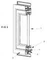
- Figs. 3 and 4 correspondingly show perspective and sectional views of a wing and frame profile members of the second embodiment of the invention for profiles divided in two parts with a heat insulating scope.
- Figures 13 and 14 are shown perspective views of alternative embodiments of door/window panel assemblies of the invention wherein the profiles are of a divided heat insulating mode.
- a frame profile member 1 and a wing profile member 2 is employed in each one of the alternative embodiments of the invention and in all various embodiments shown in Figs. 1-2, 3-4, 13, 14, the abovementioned frame profile member 1 and wing profile member 2 do exhibit a series of common characteristics.
- wing profile member 2 under all circumstances comprises:
- the polyamide profile 32a or 32b comprises a planar surface 33, the width of which corresponds to the distance separating the parts of the divided wing and frame profile members.
- the planar surface 33 extends into side protrusions 33a, 33b that are inserted within recessions being provided at symmetrically opposite ends of the parts of the divided wing and frame profile members.
- the polyamide profile 32b additionally comprises a downwardly extending inclined leg member 33c and it is employed at the bottom of the interconnected parts of the wing profile member 2.
- the downwardly extending inclined leg member 33c abuts, as will be explained hereinafter, upon an extension of the central rubber sealant 16b employed in the divided profile embodiment of the invention.
- the characteristic channel 4 of the wing profile member 2 has dimensions such as to receive the perimetrical locking mechanism comprising sequentially engaged linear and angular members with a toothed connection means being provided with projecting locking pins.
- channel 4 has preferable dimensions of width 16.3 mm, depth 11.7 mm and axial distance of 9 mm from the opposing frame profile member.
- channel 4 allowing introduction within the same of linear and angular rod members being provided with the abovementioned toothed connection means result in the advantageous system of aluminium door/window panels of the invention that not only ensures substantially enhanced perimetrical locking security, but also offers precision and speed in the assembly process that might be performed even by relatively unskilled labour.
- the engagement of an angular rod member 22 with a linear rod member 21 is performed through engagement of the male toothed end 22a of the angular rod member 22 with the female toothed end 21a of the linear rod member 21.
- Fig. 8 shows an angular rod member 22 of the invention being provided with locking pins 24 at either side thereof, these locking pins being engaged when a locking movement is performed into corresponding receiving members 23 fixedly mounted onto channel 5 of the frame profile member 1.
- Fig. 10 shows an angular rod member 22 being provided with projecting locking pins 24 being inserted within channel 4 of the wing profile member 1 of the door/window panel assembly and adjacently shows a locking pin receiving member 23 being mounted onto channel 5 of a corresponding frame profile member 1.
- Fig. 9 shows another example of part of the perimetrical locking mechanism of the invention, wherein the rotatable handle 25 is engaged with a side extension mechanism 26 of linear rod member 21 for converting rotational motion of handle 25 into linear, reciprocating motion of the linear rod member 21. Accordingly, linear rod member 21 is provided with a projecting locking pin 24 that locks within the adjacently shown receiving member 23 located within channel 5 of the frame profile member 1.
- Fig. 15 shows an overall plan of the sequentially engaged linear rod members 21 and angular rod members 22, both being provided with a desired number of locking pins 24 projecting outwards channel 4 of the wing profile member 2 and of the corresponding number of receiving members 23 located within channel 5 of the frame profile member 1.
- the overall plurality of locking pins 24 is set at a locked condition whereby all locking pins 24 are encaged within the corresponding receiving members 23 or at an unlocked condition wherein all locking pins 24 are released from corresponding receiving members 23, such locked or unlocked condition being performed by means of a simple clockwise or counterclockwise rotation respectively of the rotatable handle 25.
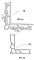
- angular reinforcing connection members 15 (Fig. 5a) and 15' (Fig. 5b) employed in the connection of frame and wing profile member sides respectively.
- Such angular reinforcing connection member is introduced within receiving channels 6 of the frame profile sides being brought into an orthogonal contact and correspondingly within channels 7 of the wing profile sides. Following introduction thereof into channels 6 or 7, the angular reinforcing connection members are pressed and fixedly mounted therein.
- Each angular reinforcing connection member 15 of the frame profile member 1 and 15' for the wing profile member 2 is provided in two alternative width dimensions, wherein the angular reinforcing connection member of the smaller width is adapted to be used in door/window panel assemblies incorporating a heat insulating interface member and the angular reinforcing connection member of the larger width is adapted to be used in door/window panel assemblies wherein the frame and wing profiles are of a compact structure.
- the configuration of the angular reinforcing connection member 15 of the frame profile member 1 is the same as that of the angular reinforcing connection member 15' of the wing profile member 2.
- angular reinforcing connection member 15 of the frame profile member is of increased thickness and is additionally provided with an arrangement of openings 15a adapted for the reception of suspension shafts of the side hinges 28 by means of which the wing profile members 1 are pivotally connected to the frame profile members 1 of the door/window panel assembly.
- each hinge 28 is provided with a pair of suspension shafts 29 which, during installation of the door/window panel assembly of the invention, are inserted and screwed within a corresponding pair of openings 15a of the reinforcing angular connection member 15.
- the elliptical configuration of openings 15a and their serial arrangement along the reinforcing angular connection member 15 are such as to ensure alternative employment of various types of commercially available hinges 28. Thanks to the extensive load receiving surface thereof, the reinforcing angular connection member 15 of the invention is capable of reliably withstanding the load of the wing panel suspended thereupon and thereby solving the problem of systems of the prior art wherein the wing panel is unreliably suspended directly from the relatively thin frame profile member.
- the circumferential rubber sealant 8 comprises a body 8c that fits within channel 9 of the wing profile member 2 at one side of the door/window panel assembly and at the other side thereof within channel 10 of the frame profile member 1.
- the body 8c of rubber sealant 8 fitted within channels 9, 10 extends into a pair of fins 8a, 8b that form an angle.
- the shorter fin 8b abuts on the side surface of either the linear leg extension member 11 of wing profile member 2 or on the side of the linear leg extension member 12 of the frame profile member 1.
- the longer fin 8a correspondingly abuts on the top end of linear leg extension member 11 or 12.
- Such configuration of the circumferential rubber sealant 8 ensures an optimally reliable air tightness and contributes towards decreasing thermal losses, since it functions in a manner such as to increase the pressure of abutment of fin 8a on the top end of linear leg extension member 11 or 12 as wind tends to press upon the shorter fin 8b increasing abutment thereof with the side surface of linear leg extension member 11 or 12.
- the central rubber sealant comprises a body 30 that is of a planar form (16b) or elongated form (16a) correspondingly in the alternative versions of divided and compact profile system of the invention. In either case the body 30 of the central rubber sealant extends into side slots 30a, 30b that slidably abut into nerves on either side of channel 14 of the frame profile member 1.
- the upwardly extending body 30 of the central rubber sealant 16a, 16b terminates at a downwardly bent fin end 31, which abuts onto a downwardly extending inclined surface 13 of the wing profile member 2 in a compact aluminium profile series and onto the downwardly extending inclined leg member 33c of the polyamide profile 32b employed in a divided aluminium profile series.
- a characterizing feature of the invention is the mushroom configuration of the locking pins 24 being provided along the aforementioned sequentially engaged linear rod members 21 and angular rod members 22.
- Each locking pin is provided with an enlarged mushroom shaped head and a circumferential recession in the cylindrical axial body underlying the enlarged mushroom shaped head so as to hook into engaging walls of the corresponding locking pin receiving member 23 of the arrangement of such receiving members 23 corresponding to the locking pins being fixedly mounted perimetrically onto the frame of the door/window panel assembly.
Landscapes
- Engineering & Computer Science (AREA)
- Civil Engineering (AREA)
- Structural Engineering (AREA)
- Mechanical Engineering (AREA)
- Specific Sealing Or Ventilating Devices For Doors And Windows (AREA)
- Wing Frames And Configurations (AREA)
- Seal Device For Vehicle (AREA)
- Special Wing (AREA)
- Window Of Vehicle (AREA)
Abstract
Description
- The invention relates in the field of the art of aluminium framed door and window panels for buildings. Specifically, the invention proposes a system of aluminium framed door/window panels characterized by a perimetrical locking capacity, a novel configuration of reinforcing angular members employed in clamping together two sides of the frame or wing sides and provisions for air tightness and heat and sound proof capacity of such door or window panels.
- Various systems of framed door and window panels are known in the prior art including among others door/window panels locked in a plurality of points. Consumer demand of burglarproof door/window panels has resulted in an increased demand for a plurality of locking points therein. EP 1219768, EP 845566 or EP 945580 all disclose door/window panel systems wherein locking together of the aluminium framed wing and frame members in a plurality of points is envisaged. However, these and other commercially available aluminium profile systems do not allow for an overall perimetrically locking device, whilst even in the confined number of locking points, locking security is rather restricted because of the rather shallow channel provided for in the wing member that does not allow reception of coupling rods of an adequate thickness. Moreover, such rather shallow channel of the wing member fails to provide an advantageously adjustable engagement of such coupling rods and instead leads to a requirement for a fixed riveting of the same.
- Known systems of aluminium framed door/window panels also do not provide for the combination of such perimetrically locked panels with a sufficiently robust configuration of angular reinforcing connection members of frame sides providing for the reception of various commercially available hinge members for the suspension of wing panels from the fixed frame and further do not provide for the combination of such perimetrically locked panels provided with angular reinforcing connection members with means of an adequately air tight and heat/sound proof closure of the wing panels onto the fixed frame.
- It is therefore an object of the present invention to advantageously overcome disadvantages and drawbacks of the prior art and provide a system of aluminium framed door/window panels with an optimally enhanced burglarproof capacity, such capacity being obtained by means of a channel in the wing member of adequate dimensions so as to receive perimetrically sequentially engaged linear and angular rods bearing a plurality of locking pins at a desired arrangement of a plurality of points, such channel also allowing employment of withdrawable and sequentially engaged linear and angular rod members provided with a toothed configuration in the connecting ends thereof.
- Another object of the invention is to provide for an advantageous mushroom configuration of the locking pins employed in the aforementioned perimetrically locked panels of the invention, wherein each locking pin is provided with an enlarged mushroom shaped head and a circumferential recession in the cylindrical axial body underlying said enlarged mushroom shaped head so as to hook into engaging walls of the corresponding locking pin receiving member, an arrangement of such receiving members corresponding to the locking pins being fixedly mounted perimetrically onto the frame of the door/window panel assembly.
- A further object of the invention is to propose embodiment of the aforementioned locking pins with the advantageous mushroom shaped head onto an arrangement of sequentially engaged linear and angular rods, mounted within the hollow sectioned perimeter of the wing member of the door/window panel assembly, said locking pins being received within a suitable plurality of receiving members fixedly mounted perimetrically around the frame member of the door/window panel assembly, wherein the perimetrically mounted plurality of locking pins may be alternatively set at a locked or unlocked condition by means of a single rotation of a rotatable handle mounted onto the wing member of the door/window panel assembly.
- Another object of the invention is to disclose an optimally designed angular reinforcing connection member of the frame or wing sides of the door/window panel assembly, wherein such angular reinforcing connection member is provided in two alternative width dimensions, so that it may selectively be employed in door/window panel assemblies incorporating a heat insulating interface member or not, such angular reinforcing connection member being provided with an arrangement of openings adapted for the reception of suspension shafts of the side hinges of the wing members of the door/window panel assembly.
- Another object of the invention is to propose alternative embodiments of the herein disclosed system of aluminium frame door/window panels with a perimetrical locking capacity as a compact system wherein each frame or wing member consists of a single aluminium profile or as a divided profile system wherein each frame or wing member consists of a pair of profiles being engaged by means of a heat insulating interface member thereby offering enhanced heat insulation properties.
- Another object of the invention is to propose in association with the herein disclosed system of aluminium framed door/window panels, optimally designed rubber fittings for exterior and interior air tight sealing of the door/window panel assembly of the invention, as well as polyamide profiles adapted to operate as heat insulating interface members in a divided profile embodiment of the invention, wherein the combination of the abovementioned rubber fittings and polyamide profiles provide an optimally air tight and heat proof performance of the door/window panel assembly of the invention under all circumstances.
- Another object of the invention is to disclose alternative profile sections and accessories in implementation of the scope of the invention.
-
- Fig. 1 shows a perspective sectional view of a frame and a wing member of the door/window panel assembly in accordance with a first preferred embodiment of the invention with a compact structure of the profiles.
- Fig. 2 shows a cross sectional view of the frame and wing profile members of Fig. 1.
- Fig. 3 shows a perspective sectional view of a frame and a wing member of the door/window panel assembly in accordance with a second preferred embodiment of the invention wherein each frame or wing member comprises a pair of profiles.
- Fig. 4 shows a cross sectional view of the frame and wing profile members of Fig. 3.
- Figures 5a, 5b present a cross sectional view of the reinforcing angular member employed in the connection of frame and wing sides respectively.
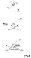
- Fig. 6 shows cross sectional views of the rubber sealant applied at the exterior perimeter of contact of the wing profile onto the frame profile and of the centrally located rubber sealants for a compact and a divided profile series respectively.
- Fig. 7 shows a cross sectional view of the polyamide profiles forming the heat insulating interface member in the divided profile series of the invention.
- Fig. 8 shows a perspective view of an angular rod of the invention being provided with locking pins, also showing a corresponding locking pin receiving member being fixedly mounted onto a frame side of the door/window panel assembly.
- Fig. 9 shows a perspective view of the rotatable handle and the reciprocatingly movable linear rod that is provided with a locking pin insertable within the adjacently shown receiving member being fixedly mounted onto a frame side.
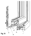
- Fig. 10 shows a perspective view of an angular rod being provided with locking pins inserted within a channel of the wing member of the door/window panel assembly and of an adjacently shown locking pin receiving member being mounted onto a corresponding frame profile member.
- Fig. 11 shows a perspective view of the hinge suspension means of a wing member onto a frame member of the door/window panel assembly of the invention.
- Fig. 12 shows a perspective view of an illustrative arrangement of toothed connection of an angular and a linear rod of the invention.
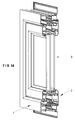
- Figs. 13 and 14 present a perspective view of other illustrative embodiments of door/window panel assemblies incorporating the perimetrical locking capacity of the invention.
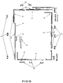
- Fig. 15 shows a planar view of parts and accessories of the perimetrically locked door/window panel assembly of the invention.
- Figs. 1 and 2 present a perspective and a sectional view of a wing and frame profile members of the first embodiment of the invention for profiles of a compact structure, whereas Figs. 3 and 4 correspondingly show perspective and sectional views of a wing and frame profile members of the second embodiment of the invention for profiles divided in two parts with a heat insulating scope. In Figures 13 and 14 are shown perspective views of alternative embodiments of door/window panel assemblies of the invention wherein the profiles are of a divided heat insulating mode.
- A
frame profile member 1 and awing profile member 2 is employed in each one of the alternative embodiments of the invention and in all various embodiments shown in Figs. 1-2, 3-4, 13, 14, the abovementionedframe profile member 1 andwing profile member 2 do exhibit a series of common characteristics. - Thus,
wing profile member 2 under all circumstances comprises: - The
characteristic channel 4 wherein are slidably inserted all various parts of the perimetrical locking assembly of the invention. - A pair of symmetrically
opposite slots 20 adapted to receivepads 20a that provide a perimetrical supporting means of theglass panel 3. - A linear
leg extension member 11 and a rubber sealant receiving slot forming extension member 9 correspondingly at one and the other side of contact of the wing and frame profile members. - An opening 7 overlying
channel 4, wherein is inserted the angular reinforcing connection member 15' of the sides of thewing profile member 2. - A
channel 5 located opposite tochannel 4 of thewing profile member 2, wherein are inserted the receiving members of the locking pins that project outwardly overlyingchannel 4. - A linear
leg extension member 12 and a rubber sealant receiving slot formingextension member 10 correspondingly at one and the other side of contact of the wing and frame profile members, wherein the linearleg extension member 12 further constitutes a side wall of theabovementioned channel 5. - An opening 6
underlying channel 5, wherein is inserted the angular reinforcingconnection member 15 of the sides of theframe profile member 1. - A
slot 14 adjacent tochannel 5 adapted to receiving the centrally located rubber sealant 16a or 16b. - In accordance with the divided aluminium profile system embodiments illustratively shown in Figs. 3, 4 and 13, 14, the two discrete parts of the
frame profile member 1 and correspondingly those of thewing profile member 2 are interconnected by means of the specially shaped reinforced polyamide profile members 32a and 32b shown in Fig. 7. - The polyamide profile 32a or 32b comprises a
planar surface 33, the width of which corresponds to the distance separating the parts of the divided wing and frame profile members. Theplanar surface 33 extends into side protrusions 33a, 33b that are inserted within recessions being provided at symmetrically opposite ends of the parts of the divided wing and frame profile members. - The polyamide profile 32b additionally comprises a downwardly extending inclined leg member 33c and it is employed at the bottom of the interconnected parts of the
wing profile member 2. The downwardly extending inclined leg member 33c abuts, as will be explained hereinafter, upon an extension of the central rubber sealant 16b employed in the divided profile embodiment of the invention. - The
characteristic channel 4 of thewing profile member 2 has dimensions such as to receive the perimetrical locking mechanism comprising sequentially engaged linear and angular members with a toothed connection means being provided with projecting locking pins. In accordance with a preferred embodiment of the invention, always within certain tolerances,channel 4 has preferable dimensions of width 16.3 mm, depth 11.7 mm and axial distance of 9 mm from the opposing frame profile member. - The configuration of
channel 4 allowing introduction within the same of linear and angular rod members being provided with the abovementioned toothed connection means result in the advantageous system of aluminium door/window panels of the invention that not only ensures substantially enhanced perimetrical locking security, but also offers precision and speed in the assembly process that might be performed even by relatively unskilled labour. Thus, as illustratively shown in Fig. 12, the engagement of anangular rod member 22 with alinear rod member 21 is performed through engagement of the male toothed end 22a of theangular rod member 22 with thefemale toothed end 21a of thelinear rod member 21. The shallow channel of reception of rod members of the prior art does not allow introduction of the toothed engaged ends proposed in the present invention and instead have to undergo the time and skill consuming process of measuring distances and accurately cutting, perforating and eventually fixedly riveting connected rod members of the locking mechanism. - Fig. 8 shows an
angular rod member 22 of the invention being provided withlocking pins 24 at either side thereof, these locking pins being engaged when a locking movement is performed into corresponding receivingmembers 23 fixedly mounted ontochannel 5 of theframe profile member 1. Fig. 10 shows anangular rod member 22 being provided with projectinglocking pins 24 being inserted withinchannel 4 of thewing profile member 1 of the door/window panel assembly and adjacently shows a lockingpin receiving member 23 being mounted ontochannel 5 of a correspondingframe profile member 1. Fig. 9 shows another example of part of the perimetrical locking mechanism of the invention, wherein therotatable handle 25 is engaged with aside extension mechanism 26 oflinear rod member 21 for converting rotational motion ofhandle 25 into linear, reciprocating motion of thelinear rod member 21. Accordingly,linear rod member 21 is provided with a projectinglocking pin 24 that locks within the adjacently shown receivingmember 23 located withinchannel 5 of theframe profile member 1. - Fig. 15 shows an overall plan of the sequentially engaged
linear rod members 21 andangular rod members 22, both being provided with a desired number oflocking pins 24 projecting outwardschannel 4 of thewing profile member 2 and of the corresponding number of receivingmembers 23 located withinchannel 5 of theframe profile member 1. The overall plurality oflocking pins 24 is set at a locked condition whereby alllocking pins 24 are encaged within the corresponding receivingmembers 23 or at an unlocked condition wherein alllocking pins 24 are released from corresponding receivingmembers 23, such locked or unlocked condition being performed by means of a simple clockwise or counterclockwise rotation respectively of therotatable handle 25. - Another characteristic feature of the invention is the optimally designed angular reinforcing connection members 15 (Fig. 5a) and 15' (Fig. 5b) employed in the connection of frame and wing profile member sides respectively. Such angular reinforcing connection member is introduced within receiving
channels 6 of the frame profile sides being brought into an orthogonal contact and correspondingly withinchannels 7 of the wing profile sides. Following introduction thereof intochannels connection member 15 of theframe profile member 1 and 15' for thewing profile member 2 is provided in two alternative width dimensions, wherein the angular reinforcing connection member of the smaller width is adapted to be used in door/window panel assemblies incorporating a heat insulating interface member and the angular reinforcing connection member of the larger width is adapted to be used in door/window panel assemblies wherein the frame and wing profiles are of a compact structure. The configuration of the angular reinforcingconnection member 15 of theframe profile member 1 is the same as that of the angular reinforcing connection member 15' of thewing profile member 2. However the angular reinforcingconnection member 15 of the frame profile member is of increased thickness and is additionally provided with an arrangement ofopenings 15a adapted for the reception of suspension shafts of the side hinges 28 by means of which thewing profile members 1 are pivotally connected to theframe profile members 1 of the door/window panel assembly. - As shown in Fig. 11, each hinge 28 is provided with a pair of
suspension shafts 29 which, during installation of the door/window panel assembly of the invention, are inserted and screwed within a corresponding pair ofopenings 15a of the reinforcingangular connection member 15. It is hereby noted that the elliptical configuration ofopenings 15a and their serial arrangement along the reinforcingangular connection member 15 are such as to ensure alternative employment of various types of commercially available hinges 28. Thanks to the extensive load receiving surface thereof, the reinforcingangular connection member 15 of the invention is capable of reliably withstanding the load of the wing panel suspended thereupon and thereby solving the problem of systems of the prior art wherein the wing panel is unreliably suspended directly from the relatively thin frame profile member. - Another characteristic feature of the invention is the ensuring of an optimum circumferential air tightness with the rubber sealants shown in Fig. 8. The
circumferential rubber sealant 8 comprises a body 8c that fits within channel 9 of thewing profile member 2 at one side of the door/window panel assembly and at the other side thereof withinchannel 10 of theframe profile member 1. The body 8c ofrubber sealant 8 fitted withinchannels 9, 10 extends into a pair of fins 8a, 8b that form an angle. When the wing panel closes onto the frame panel, the shorter fin 8b abuts on the side surface of either the linearleg extension member 11 ofwing profile member 2 or on the side of the linearleg extension member 12 of theframe profile member 1. At the same time, the longer fin 8a correspondingly abuts on the top end of linearleg extension member circumferential rubber sealant 8 ensures an optimally reliable air tightness and contributes towards decreasing thermal losses, since it functions in a manner such as to increase the pressure of abutment of fin 8a on the top end of linearleg extension member leg extension member - Another characterizing feature of the invention is the employment of the centrally located rubber sealant that alternatively takes the form 16a or 16b that is respectively being used with the aluminium framed door/window panels of the compact or the divided type. The central rubber sealant comprises a
body 30 that is of a planar form (16b) or elongated form (16a) correspondingly in the alternative versions of divided and compact profile system of the invention. In either case thebody 30 of the central rubber sealant extends into side slots 30a, 30b that slidably abut into nerves on either side ofchannel 14 of theframe profile member 1. The upwardly extendingbody 30 of the central rubber sealant 16a, 16b terminates at a downwardlybent fin end 31, which abuts onto a downwardly extendinginclined surface 13 of thewing profile member 2 in a compact aluminium profile series and onto the downwardly extending inclined leg member 33c of the polyamide profile 32b employed in a divided aluminium profile series. - A characterizing feature of the invention is the mushroom configuration of the locking pins 24 being provided along the aforementioned sequentially engaged
linear rod members 21 andangular rod members 22. Each locking pin is provided with an enlarged mushroom shaped head and a circumferential recession in the cylindrical axial body underlying the enlarged mushroom shaped head so as to hook into engaging walls of the corresponding lockingpin receiving member 23 of the arrangement of such receivingmembers 23 corresponding to the locking pins being fixedly mounted perimetrically onto the frame of the door/window panel assembly. - It must herein be noted that the description of the invention was made by reference to non-confining illustrative examples. Thus any change or amendment relating to the dimensions, design characteristics or applications of the invented object is to be considered part of the scope and the aims of the appended claims.
Claims (8)
- System of aluminium framed door/window panels comprising a frame profile member (1) and a wing profile member (2), wherein the wing profile member (2) is provided with a pair of symmetrically opposite slots (20) adapted to receive pads (20a) that provide a perimetrical supporting means of a glass panel (3), wherein, throughout the circumferential exterior and interior level of contact of the wing profile member (2) onto the frame profile member (1), the wing profile member (2) comprises a linear leg extension member (11) opposite to a slot extension (10) of the frame profile member (1) at one side thereof and a slot extension (9) opposite to a linear leg extension member (12) of the frame profile member (1) at the other end, the system of aluminium framed door/window panels being characterized by that it further comprises in combination:a channel (4) of the wing profile member (2) having dimensions such as to receive a perimetrical locking mechanism comprising sequentially engaged linear rod members (21) and angular rod members (22), said linear rod members (21) and angular rod members (22) being provided with a plurality of projecting locking pins (24) and wherein a rotatable handle (25) is engaged with a side extension mechanism (26) of a linear rod member (21) for converting rotational motion of said handle (25) into linear, reciprocating motion of the linear rod member (21) and henceforth of the overall assembly of sequentially engaged linear rod members (21) and angular rod members (22), so as to effect either a simultaneous engagement of the overall plurality of said locking pins (24) within corresponding receiving members (23) located within a channel (5) of the frame profile member (1), thereby setting said aluminium door/window panel assembly at a locked condition or a simultaneous release of all locking pins (24) from corresponding receiving members (23), thereby setting said aluminium door/window panel assembly at an unlocked condition;angular reinforcing connection members (15), (15') employed in the connection of orthogonally abutting sides of the frame profile member (1) and wing profile member (2) respectively, said angular reinforcing connection members (15), (15') being correspondingly introduced within receiving channels (6) of the frame profile sides and within receiving channels (7) of the wing profile sides, wherein following introduction thereof into said channels (6) or (7), the angular reinforcing connection members are pressed and fixedly mounted therein;a circumferential rubber sealant (8) comprising a body (8c) that fits within said slot extension (9) of the wing profile member (2) or within said slot extension (10) of the frame profile member (1) respectively throughout the exterior and interior level of contact of the wing profile member (2) onto the frame profile member (1), wherein said body (8c) of rubber sealant (8) extends into a pair of a shorter fin (8a) and a longer fin (8b) that form an angle with the shorter fin (8b) abutting on the side surface of said linear leg extension member (11) of wing profile member (2) at the exterior level of contact of the wing profile member (2) onto the frame profile member (1) and on the side of said linear leg extension member (12) of the frame profile member (1) at the interior level of contact of the wing profile member (2) onto the frame profile member (1) and with the longer fin (8a) correspondingly abutting on the top end of said linear leg extension member (11) or (12) respectively, wherein an optimally enhanced air tightness is obtained since wind forces being exerted upon said shorter fin (8b) press it in an increased abutment onto the side of said linear leg extension member (11) or (12) thereby also pulling said longer fin (8a) in an increased abutment on the top end of said linear leg extension member (11) or (12) respectively, anda centrally located rubber sealant (16a, 16b) that is mounted internally in between the pair of said circumferential rubber sealants (8) employed throughout the exterior and interior level of contact of the wing profile member (2) onto the frame profile member (1).
- System of aluminium framed door/window panels as claimed in above claim 1, characterized by that, within a certain range of tolerances and minor amendments, said channel (4) of the wing profile member (2) has a width of 16.3 mm, a depth of 11.7 mm and an axial distance of 9 mm from the opposite facing side of frame profile member (1).
- System of aluminium framed door/window panels as claimed in above claim 1, characterized by that each linear rod member (21) of the sequentially engaged arrangement of linear rod members (21) and angular rod members (22) is provided with a female toothed end and each angular rod member (22) of the sequentially engaged arrangement of linear rod members (21) and angular rod members (22) is provided with a male toothed end, whereby an enhanced accuracy with notable ease and increased speed in the assembly process of the sequentially engaged linear rod members (21) and angular rod members (22) is obtained by means of the adjustable engagement of female toothed ends (21a) of each one of the linear rod members (21) with the male toothed ends (22a) of each one of the angular rod members (22).
- System of aluminium framed door/window panels as claimed in above claim 1, characterized by that said angular reinforcing connection members (15), besides from being employed in the connection of orthogonally abutting sides of the frame profile member (1), has surfaces of increased thickness with an array of suitably spaced openings (15a) for the reception of a pair of suspension shafts (29) of a hinge (28) by means of which the wing profile member framed door/window panel is suspended from the circumferential frame, wherein during installation of the door/window panel assembly of the invention said pair of suspension shafts (29) of said hinge (28) are inserted and screwed within a corresponding pair of said suitably spaced openings (15a) of the reinforcing angular connection member (15) and wherein an elliptical configuration of said openings (15a) and their spacing along said angular reinforcing connection member (15) are such as to ensure alternative employment of various types of commercially available hinges (28).
- System of aluminium framed door/window panels as claimed in above claim 1, characterized by that said frame profile member (1) and wing profile member (2) are of a compact structure, said wing profile member (2) further comprising a polygonal surface extending in the interior thereof in between said slot extension (9) and said linear leg extension member (11), one side of said polygonal surface constituting a side wall of said channel (4) being adapted to receive said perimetrical locking mechanism and the other side of said polygonal surface comprising an inclined surface (13), a channel (14) being provided at said frame profile member (1) opposite to said polygonal surface of wing profile member (2), wherein said centrally located rubber sealant (16a) extends in between said channel (14) of the frame profile member (1) and said polygonal surface of the wing profile member (2) and comprises an elongated body (30) extending at opposing slots (30a, 30b) at one end thereof that slidably abut into nerves on either side of a channel (14) of the frame profile member (1) for fixedly mounting said rubber sealant (16a) within said channel (14) and at the other end thereof extends into a downwardly inclined fin end (31) which abuts onto said inclined surface (13) of the wing profile member (2).
- System of aluminium framed door/window panels as claimed in above claim 1, characterized by that each one of said frame profile members (1) and wing profile members (2) is divided in two independent parts being interconnected by means of a specially formed reinforced polyamide profile member (32a) adapted to operate as a heat insulation enhancing interface between said two independent parts of said frame profile members (1) and wing profile members (2), said polyamide profile member (32a) comprising a planar surface (33), the width of which corresponds to the distance separating said two independent parts of the divided wing and frame profile members, said planar surface (33) extending into side protrusions (33a, 33b) that are inserted within recessions being provided at symmetrically opposite ends of said two independent parts of the divided wing profile member (2) and frame profile member (1).
- System of aluminium framed door/window panels as claimed in above claim 6, characterized by that a specially formed reinforced polyamide profile member (32b) being employed at the lower region of interconnection of said two independent parts of the wing profile member (2) further comprises a downwardly extending inclined leg member (33c) and by that said centrally located rubber sealant (16b) comprises a planar body (30) extending into side slots (30a, 30b) at one end thereof that slidably abut into nerves on either side of said channel (14) of the frame profile member (1) for fixedly mounting said rubber sealant (16a) within said channel (14) and at the other end thereof extends into a downwardly inclined fin end (31), wherein said downwardly inclined fin end (31) abuts onto said downwardly extending inclined leg member (33c) of said polyamide profile member (32b).
- System of aluminium framed door/window panels as claimed in above claim 1, characterized by that each one of said locking pins (24) being provided along said sequentially engaged linear rod members (21) and angular rod members (22) have a mushroom configuration, each locking pin (24) being provided with an enlarged mushroom shaped head and a circumferential recession in the cylindrical axial body underlying said enlarged mushroom shaped head so as to hook into engaging walls of the corresponding locking pin receiving member (23).
Priority Applications (2)
| Application Number | Priority Date | Filing Date | Title |
|---|---|---|---|
| PL05386009T PL1619343T3 (en) | 2004-05-10 | 2005-05-10 | System of aluminium framed door/window panels |
| CY20081100176T CY1107194T1 (en) | 2004-05-10 | 2008-02-14 | DOOR / WINDOW FRAMEWORK SYSTEMS WITH ALUMINUM PROFILE |
Applications Claiming Priority (1)
| Application Number | Priority Date | Filing Date | Title |
|---|---|---|---|
| GR20040100174A GR1004910B (en) | 2004-05-10 | 2004-05-10 | System of sashes made of compact aluminium profile |
Publications (3)
| Publication Number | Publication Date |
|---|---|
| EP1619343A2 true EP1619343A2 (en) | 2006-01-25 |
| EP1619343A3 EP1619343A3 (en) | 2006-09-20 |
| EP1619343B1 EP1619343B1 (en) | 2007-11-14 |
Family
ID=38566162
Family Applications (1)
| Application Number | Title | Priority Date | Filing Date |
|---|---|---|---|
| EP05386009A Expired - Lifetime EP1619343B1 (en) | 2004-05-10 | 2005-05-10 | System of aluminium framed door/window panels |
Country Status (8)
| Country | Link |
|---|---|
| EP (1) | EP1619343B1 (en) |
| AT (1) | ATE378490T1 (en) |
| DE (1) | DE602005003271T2 (en) |
| DK (1) | DK1619343T3 (en) |
| ES (1) | ES2297654T3 (en) |
| GR (1) | GR1004910B (en) |
| PL (1) | PL1619343T3 (en) |
| PT (1) | PT1619343E (en) |
Cited By (11)
| Publication number | Priority date | Publication date | Assignee | Title |
|---|---|---|---|---|
| DE102008030635A1 (en) * | 2008-07-01 | 2010-01-14 | LEICHT - Fenster und Türen GmbH | Window- or door profile for closing e.g. building opening, has groove formed in stop region and formed such that air flow penetrating between stationary part and opening-/closable part is deflected in whirling motion |
| CN101476436B (en) * | 2008-12-01 | 2011-11-16 | 陈洪法 | Aluminum alloy concealed sliding anti-theft window |
| DE202013101148U1 (en) | 2012-03-21 | 2013-04-24 | Marek Trzcinski | Set of window or door profiles made of plastic |
| PT107117A (en) * | 2013-08-13 | 2015-02-13 | Brás & Gonçalves Sist S De Caixilharia Lda B | CAIXILIARIA TO MAKE DOORS OR WINDOWS OF LARGE AREAS |
| WO2015193692A1 (en) * | 2014-06-16 | 2015-12-23 | Tzika Asimo | Device for delivering an insulation enhancing polyurethane foam within profiles used in doors, windows and related applications |
| CN106088937A (en) * | 2016-08-12 | 2016-11-09 | 河南恒美铝业有限公司 | A kind of aluminium alloy out-open window |
| CN106088936A (en) * | 2016-08-12 | 2016-11-09 | 河南恒美铝业有限公司 | A kind of aluminium alloy out-open window |
| CN106088932A (en) * | 2016-08-12 | 2016-11-09 | 河南恒美铝业有限公司 | A kind of aluminium alloy out-open window |
| CN106088935A (en) * | 2016-08-12 | 2016-11-09 | 河南恒美铝业有限公司 | A kind of aluminium alloy out-open window |
| CN106121445A (en) * | 2016-08-12 | 2016-11-16 | 河南恒美铝业有限公司 | A kind of aluminium alloy out-open window |
| DE102019001692A1 (en) * | 2019-03-11 | 2020-09-17 | Karim Bouzrara | Process for improving burglary protection |
Families Citing this family (6)
| Publication number | Priority date | Publication date | Assignee | Title |
|---|---|---|---|---|
| ITBO20050695A1 (en) * | 2005-11-15 | 2007-05-16 | Gsg Int Spa | DOOR LOCK WITH DOOR OPENING |
| CN101476437B (en) * | 2008-12-01 | 2011-06-29 | 陈洪法 | Plastic-steel concealed and fixed anti-theft window |
| ES2496240B1 (en) * | 2013-03-18 | 2015-11-19 | Roberto DE MIGUEL SANCHO | Sliding hurricane window |
| CN106088930A (en) * | 2016-08-12 | 2016-11-09 | 河南恒美铝业有限公司 | A kind of aluminium alloy out-open window |
| CN106088931A (en) * | 2016-08-12 | 2016-11-09 | 河南恒美铝业有限公司 | A kind of aluminium alloy out-open window |
| CN106088933B (en) * | 2016-08-12 | 2018-10-30 | 河南恒美铝业有限公司 | A kind of aluminium alloy out-open window |
Family Cites Families (4)
| Publication number | Priority date | Publication date | Assignee | Title |
|---|---|---|---|---|
| EP0845566A3 (en) * | 1996-12-02 | 1999-01-13 | Exacta-Fenster-Bau GmbH | Wing assembly |
| NL1015090C2 (en) * | 2000-05-02 | 2001-11-05 | Reynolds Aluminium Bv | Cargo space, with watertight closing doors. |
| IT1314886B1 (en) * | 2000-12-13 | 2003-01-16 | Euroinvest S R L | MECHANICAL CONNECTION OF USE INSIDE PERIMETER ANCHORING DEVICES FOR ANTI-THEFT FRAME DOORS IN METAL PROFILE |
| DE10246932A1 (en) * | 2002-10-08 | 2004-04-22 | Aluplast Gmbh | Seal for a window profile and process for its manufacture |
-
2004
- 2004-05-10 GR GR20040100174A patent/GR1004910B/en active IP Right Grant
-
2005
- 2005-05-10 PL PL05386009T patent/PL1619343T3/en unknown
- 2005-05-10 DE DE602005003271T patent/DE602005003271T2/en not_active Expired - Lifetime
- 2005-05-10 AT AT05386009T patent/ATE378490T1/en active
- 2005-05-10 DK DK05386009T patent/DK1619343T3/en active
- 2005-05-10 PT PT05386009T patent/PT1619343E/en unknown
- 2005-05-10 EP EP05386009A patent/EP1619343B1/en not_active Expired - Lifetime
- 2005-05-10 ES ES05386009T patent/ES2297654T3/en not_active Expired - Lifetime
Cited By (14)
| Publication number | Priority date | Publication date | Assignee | Title |
|---|---|---|---|---|
| DE102008030635A1 (en) * | 2008-07-01 | 2010-01-14 | LEICHT - Fenster und Türen GmbH | Window- or door profile for closing e.g. building opening, has groove formed in stop region and formed such that air flow penetrating between stationary part and opening-/closable part is deflected in whirling motion |
| CN101476436B (en) * | 2008-12-01 | 2011-11-16 | 陈洪法 | Aluminum alloy concealed sliding anti-theft window |
| DE202013101148U1 (en) | 2012-03-21 | 2013-04-24 | Marek Trzcinski | Set of window or door profiles made of plastic |
| PT107117B (en) * | 2013-08-13 | 2020-06-30 | B.Brás & Gonçalves -Sistemas De Caixilharia, Lda. | FRAME TO MAKE DOORS OR WINDOWS OF LARGE AREAS |
| PT107117A (en) * | 2013-08-13 | 2015-02-13 | Brás & Gonçalves Sist S De Caixilharia Lda B | CAIXILIARIA TO MAKE DOORS OR WINDOWS OF LARGE AREAS |
| EP2853674A2 (en) | 2013-08-13 | 2015-04-01 | B. Bras & Goncalves-Sistema de Caixilharia, LDA | Framework for manufacturing doors or windows of large dimensions |
| WO2015193692A1 (en) * | 2014-06-16 | 2015-12-23 | Tzika Asimo | Device for delivering an insulation enhancing polyurethane foam within profiles used in doors, windows and related applications |
| CN106088937A (en) * | 2016-08-12 | 2016-11-09 | 河南恒美铝业有限公司 | A kind of aluminium alloy out-open window |
| CN106088932A (en) * | 2016-08-12 | 2016-11-09 | 河南恒美铝业有限公司 | A kind of aluminium alloy out-open window |
| CN106088935A (en) * | 2016-08-12 | 2016-11-09 | 河南恒美铝业有限公司 | A kind of aluminium alloy out-open window |
| CN106121445A (en) * | 2016-08-12 | 2016-11-16 | 河南恒美铝业有限公司 | A kind of aluminium alloy out-open window |
| CN106088936A (en) * | 2016-08-12 | 2016-11-09 | 河南恒美铝业有限公司 | A kind of aluminium alloy out-open window |
| DE102019001692A1 (en) * | 2019-03-11 | 2020-09-17 | Karim Bouzrara | Process for improving burglary protection |
| DE102019001692B4 (en) * | 2019-03-11 | 2020-09-24 | Karim Bouzrara | Process for improving burglary protection |
Also Published As
| Publication number | Publication date |
|---|---|
| ATE378490T1 (en) | 2007-11-15 |
| DE602005003271T2 (en) | 2008-09-18 |
| ES2297654T3 (en) | 2008-05-01 |
| PL1619343T3 (en) | 2008-04-30 |
| EP1619343B1 (en) | 2007-11-14 |
| EP1619343A3 (en) | 2006-09-20 |
| GR1004910B (en) | 2005-06-09 |
| DE602005003271D1 (en) | 2007-12-27 |
| DK1619343T3 (en) | 2008-03-25 |
| PT1619343E (en) | 2008-02-22 |
Similar Documents
| Publication | Publication Date | Title |
|---|---|---|
| EP1619343B1 (en) | System of aluminium framed door/window panels | |
| US7313890B2 (en) | Wall opening support system | |
| CA1321511C (en) | Prefabricated glazing gasket | |
| EP2141314B1 (en) | System of lift-and-slide aluminium framed door/window panels | |
| KR101471088B1 (en) | Adiabatic Metal Windows | |
| US20090166494A1 (en) | Mounting system, especially for solar modules | |
| US4008552A (en) | Wall structure and elements therefor | |
| WO2010013233A2 (en) | Double pane panel unit and method of assembling same | |
| HU201820B (en) | Skylight as well as corner shape for building-in skylight | |
| WO2005031087A1 (en) | A temporary closure | |
| US6574927B2 (en) | Fitting for a window and parts for such fitting | |
| US3881287A (en) | Glass framing system | |
| US5687529A (en) | Fastening device | |
| US7509780B2 (en) | Joint for the angular connection of door window profile frames and the like | |
| KR102053956B1 (en) | Bracket assembly and window system and window construction structure on external insulation wall having the same | |
| US20070193152A1 (en) | Building block assembly system | |
| US3734552A (en) | House door latching device | |
| PL212637B1 (en) | Assembly of the interlocking seat in the frame, preferably in the roof window frame | |
| EP1219768A2 (en) | Mechanical junction assembly for perimetrical locking device of wings of burglarproof doors and windows made of metallic profiles | |
| EP2017427A2 (en) | Multi-function system for assembling profiles | |
| EP1571270A1 (en) | Connecting device | |
| JPH0372773B2 (en) | ||
| KR200146934Y1 (en) | Door assembling structure of double lattice winddows and doors | |
| JP3030535B2 (en) | Roof structure | |
| EP1691022A2 (en) | Corner piece and joinery which is provided with such a corner piece |
Legal Events
| Date | Code | Title | Description |
|---|---|---|---|
| PUAI | Public reference made under article 153(3) epc to a published international application that has entered the european phase |
Free format text: ORIGINAL CODE: 0009012 |
|
| AK | Designated contracting states |
Kind code of ref document: A2 Designated state(s): AT BE BG CH CY CZ DE DK EE ES FI FR GB GR HU IE IS IT LI LT LU MC NL PL PT RO SE SI SK TR |
|
| AX | Request for extension of the european patent |
Extension state: AL BA HR LV MK YU |
|
| PUAL | Search report despatched |
Free format text: ORIGINAL CODE: 0009013 |
|
| 17P | Request for examination filed |
Effective date: 20060728 |
|
| AK | Designated contracting states |
Kind code of ref document: A3 Designated state(s): AT BE BG CH CY CZ DE DK EE ES FI FR GB GR HU IE IS IT LI LT LU MC NL PL PT RO SE SI SK TR |
|
| AX | Request for extension of the european patent |
Extension state: AL BA HR LV MK YU |
|
| AKX | Designation fees paid |
Designated state(s): AT BE BG CH CY CZ DE DK EE ES FI FR GB GR HU IE IS IT LI LT LU MC NL PL PT RO SE SI SK TR |
|
| AXX | Extension fees paid |
Extension state: AL Payment date: 20060728 Extension state: MK Payment date: 20060728 |
|
| GRAP | Despatch of communication of intention to grant a patent |
Free format text: ORIGINAL CODE: EPIDOSNIGR1 |
|
| GRAS | Grant fee paid |
Free format text: ORIGINAL CODE: EPIDOSNIGR3 |
|
| GRAA | (expected) grant |
Free format text: ORIGINAL CODE: 0009210 |
|
| AK | Designated contracting states |
Kind code of ref document: B1 Designated state(s): AT BE BG CH CY CZ DE DK EE ES FI FR GB GR HU IE IS IT LI LT LU MC NL PL PT RO SE SI SK TR |
|
| AX | Request for extension of the european patent |
Extension state: AL MK |
|
| REG | Reference to a national code |
Ref country code: GB Ref legal event code: FG4D |
|
| REG | Reference to a national code |
Ref country code: CH Ref legal event code: EP |
|
| REG | Reference to a national code |
Ref country code: IE Ref legal event code: FG4D |
|
| REF | Corresponds to: |
Ref document number: 602005003271 Country of ref document: DE Date of ref document: 20071227 Kind code of ref document: P |
|
| REG | Reference to a national code |
Ref country code: RO Ref legal event code: EPE |
|
| REG | Reference to a national code |
Ref country code: PT Ref legal event code: SC4A Free format text: AVAILABILITY OF NATIONAL TRANSLATION Effective date: 20080213 |
|
| REG | Reference to a national code |
Ref country code: CH Ref legal event code: NV Representative=s name: ABREMA AGENCE BREVET ET MARQUES, GANGUILLET |
|
| REG | Reference to a national code |
Ref country code: SE Ref legal event code: TRGR |
|
| REG | Reference to a national code |
Ref country code: DK Ref legal event code: T3 |
|
| REG | Reference to a national code |
Ref country code: PL Ref legal event code: T3 |
|
| REG | Reference to a national code |
Ref country code: ES Ref legal event code: FG2A Ref document number: 2297654 Country of ref document: ES Kind code of ref document: T3 |
|
| PG25 | Lapsed in a contracting state [announced via postgrant information from national office to epo] |
Ref country code: SI Free format text: LAPSE BECAUSE OF FAILURE TO SUBMIT A TRANSLATION OF THE DESCRIPTION OR TO PAY THE FEE WITHIN THE PRESCRIBED TIME-LIMIT Effective date: 20071114 Ref country code: IS Free format text: LAPSE BECAUSE OF FAILURE TO SUBMIT A TRANSLATION OF THE DESCRIPTION OR TO PAY THE FEE WITHIN THE PRESCRIBED TIME-LIMIT Effective date: 20080314 Ref country code: LT Free format text: LAPSE BECAUSE OF FAILURE TO SUBMIT A TRANSLATION OF THE DESCRIPTION OR TO PAY THE FEE WITHIN THE PRESCRIBED TIME-LIMIT Effective date: 20071114 |
|
| ET | Fr: translation filed | ||
| PLBE | No opposition filed within time limit |
Free format text: ORIGINAL CODE: 0009261 |
|
| STAA | Information on the status of an ep patent application or granted ep patent |
Free format text: STATUS: NO OPPOSITION FILED WITHIN TIME LIMIT |
|
| 26N | No opposition filed |
Effective date: 20080815 |
|
| REG | Reference to a national code |
Ref country code: HU Ref legal event code: AG4A Ref document number: E003468 Country of ref document: HU |
|
| PG25 | Lapsed in a contracting state [announced via postgrant information from national office to epo] |
Ref country code: MC Free format text: LAPSE BECAUSE OF NON-PAYMENT OF DUE FEES Effective date: 20080531 |
|
| PG25 | Lapsed in a contracting state [announced via postgrant information from national office to epo] |
Ref country code: GR Free format text: LAPSE BECAUSE OF FAILURE TO SUBMIT A TRANSLATION OF THE DESCRIPTION OR TO PAY THE FEE WITHIN THE PRESCRIBED TIME-LIMIT Effective date: 20080215 Ref country code: EE Free format text: LAPSE BECAUSE OF FAILURE TO SUBMIT A TRANSLATION OF THE DESCRIPTION OR TO PAY THE FEE WITHIN THE PRESCRIBED TIME-LIMIT Effective date: 20071114 |
|
| PG25 | Lapsed in a contracting state [announced via postgrant information from national office to epo] |
Ref country code: BG Free format text: LAPSE BECAUSE OF NON-PAYMENT OF DUE FEES Effective date: 20081031 |
|
| PGRI | Patent reinstated in contracting state [announced from national office to epo] |
Ref country code: BG Effective date: 20090520 |
|
| PG25 | Lapsed in a contracting state [announced via postgrant information from national office to epo] |
Ref country code: LU Free format text: LAPSE BECAUSE OF NON-PAYMENT OF DUE FEES Effective date: 20080510 |
|
| PGFP | Annual fee paid to national office [announced via postgrant information from national office to epo] |
Ref country code: ES Payment date: 20110530 Year of fee payment: 7 Ref country code: FR Payment date: 20110523 Year of fee payment: 7 Ref country code: CH Payment date: 20110512 Year of fee payment: 7 Ref country code: CZ Payment date: 20110509 Year of fee payment: 7 Ref country code: SE Payment date: 20110524 Year of fee payment: 7 Ref country code: TR Payment date: 20110506 Year of fee payment: 7 Ref country code: IE Payment date: 20110523 Year of fee payment: 7 Ref country code: PT Payment date: 20110509 Year of fee payment: 7 |
|
| PGFP | Annual fee paid to national office [announced via postgrant information from national office to epo] |
Ref country code: BE Payment date: 20110511 Year of fee payment: 7 Ref country code: FI Payment date: 20110519 Year of fee payment: 7 Ref country code: DK Payment date: 20110512 Year of fee payment: 7 Ref country code: AT Payment date: 20110512 Year of fee payment: 7 Ref country code: PL Payment date: 20110509 Year of fee payment: 7 Ref country code: SK Payment date: 20110509 Year of fee payment: 7 Ref country code: HU Payment date: 20110506 Year of fee payment: 7 Ref country code: GB Payment date: 20110513 Year of fee payment: 7 Ref country code: NL Payment date: 20110524 Year of fee payment: 7 |
|
| PGFP | Annual fee paid to national office [announced via postgrant information from national office to epo] |
Ref country code: IT Payment date: 20110518 Year of fee payment: 7 Ref country code: DE Payment date: 20110606 Year of fee payment: 7 |
|
| PGFP | Annual fee paid to national office [announced via postgrant information from national office to epo] |
Ref country code: CY Payment date: 20110509 Year of fee payment: 7 |
|
| REG | Reference to a national code |
Ref country code: PT Ref legal event code: MM4A Free format text: LAPSE DUE TO NON-PAYMENT OF FEES Effective date: 20121112 |
|
| BERE | Be: lapsed |
Owner name: HELLENIC ALUMINIUM INDUSTRY ELVIAL S.A. Effective date: 20120531 |
|
| REG | Reference to a national code |
Ref country code: NL Ref legal event code: V1 Effective date: 20121201 |
|
| REG | Reference to a national code |
Ref country code: CH Ref legal event code: PL |
|
| REG | Reference to a national code |
Ref country code: SE Ref legal event code: EUG |
|
| REG | Reference to a national code |
Ref country code: AT Ref legal event code: MM01 Ref document number: 378490 Country of ref document: AT Kind code of ref document: T Effective date: 20120510 |
|
| REG | Reference to a national code |
Ref country code: DK Ref legal event code: EBP |
|
| GBPC | Gb: european patent ceased through non-payment of renewal fee |
Effective date: 20120510 |
|
| PG25 | Lapsed in a contracting state [announced via postgrant information from national office to epo] |
Ref country code: CH Free format text: LAPSE BECAUSE OF NON-PAYMENT OF DUE FEES Effective date: 20120531 Ref country code: AT Free format text: LAPSE BECAUSE OF NON-PAYMENT OF DUE FEES Effective date: 20120510 Ref country code: CY Free format text: LAPSE BECAUSE OF NON-PAYMENT OF DUE FEES Effective date: 20120510 Ref country code: CZ Free format text: LAPSE BECAUSE OF NON-PAYMENT OF DUE FEES Effective date: 20120510 Ref country code: LI Free format text: LAPSE BECAUSE OF NON-PAYMENT OF DUE FEES Effective date: 20120531 Ref country code: FI Free format text: LAPSE BECAUSE OF NON-PAYMENT OF DUE FEES Effective date: 20120510 Ref country code: SK Free format text: LAPSE BECAUSE OF NON-PAYMENT OF DUE FEES Effective date: 20120510 Ref country code: HU Free format text: LAPSE BECAUSE OF NON-PAYMENT OF DUE FEES Effective date: 20120511 |
|
| REG | Reference to a national code |
Ref country code: SK Ref legal event code: MM4A Ref document number: E 2997 Country of ref document: SK Effective date: 20120510 |
|
| REG | Reference to a national code |
Ref country code: IE Ref legal event code: MM4A |
|
| PG25 | Lapsed in a contracting state [announced via postgrant information from national office to epo] |
Ref country code: BE Free format text: LAPSE BECAUSE OF NON-PAYMENT OF DUE FEES Effective date: 20120531 Ref country code: IT Free format text: LAPSE BECAUSE OF NON-PAYMENT OF DUE FEES Effective date: 20120510 Ref country code: SE Free format text: LAPSE BECAUSE OF NON-PAYMENT OF DUE FEES Effective date: 20120511 Ref country code: PT Free format text: LAPSE BECAUSE OF NON-PAYMENT OF DUE FEES Effective date: 20121112 |
|
| REG | Reference to a national code |
Ref country code: FR Ref legal event code: ST Effective date: 20130131 |
|
| REG | Reference to a national code |
Ref country code: DE Ref legal event code: R119 Ref document number: 602005003271 Country of ref document: DE Effective date: 20121201 |
|
| PG25 | Lapsed in a contracting state [announced via postgrant information from national office to epo] |
Ref country code: NL Free format text: LAPSE BECAUSE OF NON-PAYMENT OF DUE FEES Effective date: 20121201 |
|
| PG25 | Lapsed in a contracting state [announced via postgrant information from national office to epo] |
Ref country code: RO Free format text: LAPSE BECAUSE OF NON-PAYMENT OF DUE FEES Effective date: 20120510 Ref country code: GB Free format text: LAPSE BECAUSE OF NON-PAYMENT OF DUE FEES Effective date: 20120510 Ref country code: IE Free format text: LAPSE BECAUSE OF NON-PAYMENT OF DUE FEES Effective date: 20120510 Ref country code: DK Free format text: LAPSE BECAUSE OF NON-PAYMENT OF DUE FEES Effective date: 20120531 Ref country code: FR Free format text: LAPSE BECAUSE OF NON-PAYMENT OF DUE FEES Effective date: 20120531 |
|
| PG25 | Lapsed in a contracting state [announced via postgrant information from national office to epo] |
Ref country code: DE Free format text: LAPSE BECAUSE OF NON-PAYMENT OF DUE FEES Effective date: 20121201 |
|
| PG25 | Lapsed in a contracting state [announced via postgrant information from national office to epo] |
Ref country code: BG Free format text: LAPSE BECAUSE OF NON-PAYMENT OF DUE FEES Effective date: 20121231 |
|
| REG | Reference to a national code |
Ref country code: ES Ref legal event code: FD2A Effective date: 20130820 |
|
| PG25 | Lapsed in a contracting state [announced via postgrant information from national office to epo] |
Ref country code: PL Free format text: LAPSE BECAUSE OF NON-PAYMENT OF DUE FEES Effective date: 20120510 |
|
| REG | Reference to a national code |
Ref country code: PL Ref legal event code: LAPE |
|
| PG25 | Lapsed in a contracting state [announced via postgrant information from national office to epo] |
Ref country code: ES Free format text: LAPSE BECAUSE OF NON-PAYMENT OF DUE FEES Effective date: 20120511 |
|
| PG25 | Lapsed in a contracting state [announced via postgrant information from national office to epo] |
Ref country code: TR Free format text: LAPSE BECAUSE OF NON-PAYMENT OF DUE FEES Effective date: 20120510 |
|
| PGFP | Annual fee paid to national office [announced via postgrant information from national office to epo] |
Ref country code: RO Payment date: 20190506 Year of fee payment: 15 Ref country code: BG Payment date: 20190515 Year of fee payment: 15 |
|
| PG25 | Lapsed in a contracting state [announced via postgrant information from national office to epo] |
Ref country code: BG Free format text: LAPSE BECAUSE OF NON-PAYMENT OF DUE FEES Effective date: 20201130 Ref country code: RO Free format text: LAPSE BECAUSE OF NON-PAYMENT OF DUE FEES Effective date: 20200510 |