EP1618313B1 - Electric brake for aircraft - Google Patents
Electric brake for aircraft Download PDFInfo
- Publication number
- EP1618313B1 EP1618313B1 EP04750885.8A EP04750885A EP1618313B1 EP 1618313 B1 EP1618313 B1 EP 1618313B1 EP 04750885 A EP04750885 A EP 04750885A EP 1618313 B1 EP1618313 B1 EP 1618313B1
- Authority
- EP
- European Patent Office
- Prior art keywords
- ram
- brake
- actuator module
- module
- electric motor
- Prior art date
- Legal status (The legal status is an assumption and is not a legal conclusion. Google has not performed a legal analysis and makes no representation as to the accuracy of the status listed.)
- Expired - Lifetime
Links
Images



Classifications
-
- F—MECHANICAL ENGINEERING; LIGHTING; HEATING; WEAPONS; BLASTING
- F16—ENGINEERING ELEMENTS AND UNITS; GENERAL MEASURES FOR PRODUCING AND MAINTAINING EFFECTIVE FUNCTIONING OF MACHINES OR INSTALLATIONS; THERMAL INSULATION IN GENERAL
- F16D—COUPLINGS FOR TRANSMITTING ROTATION; CLUTCHES; BRAKES
- F16D65/00—Parts or details
- F16D65/14—Actuating mechanisms for brakes; Means for initiating operation at a predetermined position
- F16D65/16—Actuating mechanisms for brakes; Means for initiating operation at a predetermined position arranged in or on the brake
- F16D65/18—Actuating mechanisms for brakes; Means for initiating operation at a predetermined position arranged in or on the brake adapted for drawing members together, e.g. for disc brakes
-
- B—PERFORMING OPERATIONS; TRANSPORTING
- B60—VEHICLES IN GENERAL
- B60T—VEHICLE BRAKE CONTROL SYSTEMS OR PARTS THEREOF; BRAKE CONTROL SYSTEMS OR PARTS THEREOF, IN GENERAL; ARRANGEMENT OF BRAKING ELEMENTS ON VEHICLES IN GENERAL; PORTABLE DEVICES FOR PREVENTING UNWANTED MOVEMENT OF VEHICLES; VEHICLE MODIFICATIONS TO FACILITATE COOLING OF BRAKES
- B60T13/00—Transmitting braking action from initiating means to ultimate brake actuator with power assistance or drive; Brake systems incorporating such transmitting means, e.g. air-pressure brake systems
- B60T13/74—Transmitting braking action from initiating means to ultimate brake actuator with power assistance or drive; Brake systems incorporating such transmitting means, e.g. air-pressure brake systems with electrical assistance or drive
- B60T13/741—Transmitting braking action from initiating means to ultimate brake actuator with power assistance or drive; Brake systems incorporating such transmitting means, e.g. air-pressure brake systems with electrical assistance or drive acting on an ultimate actuator
-
- B—PERFORMING OPERATIONS; TRANSPORTING
- B64—AIRCRAFT; AVIATION; COSMONAUTICS
- B64C—AEROPLANES; HELICOPTERS
- B64C25/00—Alighting gear
- B64C25/32—Alighting gear characterised by elements which contact the ground or similar surface
- B64C25/42—Arrangement or adaptation of brakes
- B64C25/44—Actuating mechanisms
-
- F—MECHANICAL ENGINEERING; LIGHTING; HEATING; WEAPONS; BLASTING
- F16—ENGINEERING ELEMENTS AND UNITS; GENERAL MEASURES FOR PRODUCING AND MAINTAINING EFFECTIVE FUNCTIONING OF MACHINES OR INSTALLATIONS; THERMAL INSULATION IN GENERAL
- F16D—COUPLINGS FOR TRANSMITTING ROTATION; CLUTCHES; BRAKES
- F16D55/00—Brakes with substantially-radial braking surfaces pressed together in axial direction, e.g. disc brakes
- F16D2055/0075—Constructional features of axially engaged brakes
- F16D2055/0091—Plural actuators arranged side by side on the same side of the rotor
-
- F—MECHANICAL ENGINEERING; LIGHTING; HEATING; WEAPONS; BLASTING
- F16—ENGINEERING ELEMENTS AND UNITS; GENERAL MEASURES FOR PRODUCING AND MAINTAINING EFFECTIVE FUNCTIONING OF MACHINES OR INSTALLATIONS; THERMAL INSULATION IN GENERAL
- F16D—COUPLINGS FOR TRANSMITTING ROTATION; CLUTCHES; BRAKES
- F16D66/00—Arrangements for monitoring working conditions, e.g. wear, temperature
- F16D2066/003—Position, angle or speed
-
- F—MECHANICAL ENGINEERING; LIGHTING; HEATING; WEAPONS; BLASTING
- F16—ENGINEERING ELEMENTS AND UNITS; GENERAL MEASURES FOR PRODUCING AND MAINTAINING EFFECTIVE FUNCTIONING OF MACHINES OR INSTALLATIONS; THERMAL INSULATION IN GENERAL
- F16D—COUPLINGS FOR TRANSMITTING ROTATION; CLUTCHES; BRAKES
- F16D2121/00—Type of actuator operation force
- F16D2121/18—Electric or magnetic
- F16D2121/24—Electric or magnetic using motors
-
- F—MECHANICAL ENGINEERING; LIGHTING; HEATING; WEAPONS; BLASTING
- F16—ENGINEERING ELEMENTS AND UNITS; GENERAL MEASURES FOR PRODUCING AND MAINTAINING EFFECTIVE FUNCTIONING OF MACHINES OR INSTALLATIONS; THERMAL INSULATION IN GENERAL
- F16D—COUPLINGS FOR TRANSMITTING ROTATION; CLUTCHES; BRAKES
- F16D2125/00—Components of actuators
- F16D2125/18—Mechanical mechanisms
- F16D2125/20—Mechanical mechanisms converting rotation to linear movement or vice versa
- F16D2125/34—Mechanical mechanisms converting rotation to linear movement or vice versa acting in the direction of the axis of rotation
- F16D2125/40—Screw-and-nut
-
- F—MECHANICAL ENGINEERING; LIGHTING; HEATING; WEAPONS; BLASTING
- F16—ENGINEERING ELEMENTS AND UNITS; GENERAL MEASURES FOR PRODUCING AND MAINTAINING EFFECTIVE FUNCTIONING OF MACHINES OR INSTALLATIONS; THERMAL INSULATION IN GENERAL
- F16D—COUPLINGS FOR TRANSMITTING ROTATION; CLUTCHES; BRAKES
- F16D2125/00—Components of actuators
- F16D2125/18—Mechanical mechanisms
- F16D2125/44—Mechanical mechanisms transmitting rotation
- F16D2125/46—Rotating members in mutual engagement
- F16D2125/48—Rotating members in mutual engagement with parallel stationary axes, e.g. spur gears
-
- F—MECHANICAL ENGINEERING; LIGHTING; HEATING; WEAPONS; BLASTING
- F16—ENGINEERING ELEMENTS AND UNITS; GENERAL MEASURES FOR PRODUCING AND MAINTAINING EFFECTIVE FUNCTIONING OF MACHINES OR INSTALLATIONS; THERMAL INSULATION IN GENERAL
- F16D—COUPLINGS FOR TRANSMITTING ROTATION; CLUTCHES; BRAKES
- F16D2127/00—Auxiliary mechanisms
- F16D2127/06—Locking mechanisms, e.g. acting on actuators, on release mechanisms or on force transmission mechanisms
Definitions
- the invention herein described relates generally to an electric brake particularly useful in aircraft, and more particularly to an electric brake actuator assembly, components thereof, and associated methods of assembly and operation.
- aircraft wheel and brake assemblies including a non-rotatable wheel support, a wheel mounted to the wheel support for rotation, and a brake disk stack having front and rear axial ends and alternating rotor and stator disks mounted with respect to the wheel support and wheel for relative axial movement.
- Each rotor disk is coupled to the wheel for rotation therewith and each stator disk is coupled to the wheel support against rotation.
- a back plate is located at the rear end of the disk stack and a brake head is located at the front end.
- the brake head houses a plurality of actuator rams that extend to compress the brake disk stack against the back plate. Torque is taken out by the stator disks through a static torque tube or the like.
- U.S. Patent No. 4,596,316 another configuration of an electrically actuated brake uses a roller screw drive wherein a ring gear member interacts through a plurality of roller screws to drive a ram member into engagement with the brake pressure plate to effect compression of the brake disk stack for braking action.
- a plurality of electric motors and their associated pinions drive a ring gear into rotation and the plurality of roller screws effect linear axial movement of the ram member.
- a further electrically actuated aircraft brake employs a roller screw drive mechanism driven by an electric torque motor through a gear drive associated with either the screw or the nut of the roller screw drive mechanism. Rotation of the gear drive by the torque motor moves the other one of the screw or nut into axial engagement with a brake disk stack to compress the stack for braking.
- a plurality of the roller screw drive mechanisms and respective gear drives and torque motors are mounted in a balanced arrangement about the axis of the wheel to apply and release a brake pressure force on the brake disk stack in response to an electrical control signal to the torque motors.
- U.S. Patent No. 6,095,293 discloses an electric brake and method characterized by the use actuator modules each of which can be easily and quickly replaced as a unit. This enables quick and easy replacement of the actuator modules without requiring disassembly of the overall brake and wheel assembly. Also, it is conceivable that a malfunctioning actuator module could be replaced on an aircraft and tested with a minimum of equipment preferably quickly enough to allow the aircraft to remain in scheduled service and/or with a minimum of downtime. In addition, periodic maintenance of the brake can be done quicker and more efficiently by replacing the actuator modules with reconditioned and/or new actuator modules.
- the electric brake described in U. S. Patent No. 6,095,293 comprises a brake disk stack, a brake head, and at least one actuator module mounted to the brake head.
- the actuator module includes a module housing, a reciprocating ram and a motive device, i.e, an electric motor, operatively connected to the reciprocating ram for selectively moving the reciprocating ram into and out of forceful engagement with the brake disk stack for applying and releasing braking force.
- the actuator module is removable as a unit from one side of the brake head and most preferably from the side of the brake head opposite the brake disk stack.
- the ram includes a ram nut, and the electric motor is drivingly connected to a lead screw, e.g.
- the module housing includes a guideway for guiding the ram nut, and the guideway and ram nut respectively have polygonal cross-sections defined by plural outer side surfaces which rotationally interfere with one another to restrain rotation of the ram nut relative to the housing.
- the present invention provides a number of improvements over known electric brakes.
- the present invention provides an electric brake actuator module comprising: a module housing having a guideway; and a reciprocating ram axially movable in the guideway, the ram having an inner portion of non-circular cross-section and an outer portion of circular cross-section, and the guideway having an inner portion of non-circular cross-section for interacting with the inner portion of the ram to prevent rotation of the inner portion of the ram and to determine a stroke of the ram, and an outer portion of circular cross-section sealed with respect to the outer portion of the ram.
- the brake 10 generally comprises a brake actuator assembly 11 and a heat sink in the form of a brake disk stack 12.
- the brake disk stack 12 can be of a conventional design including stationary brake elements and rotary brake elements that are interleaved and surround a torque tube or equivalent (not shown).
- the stationary and rotary brake elements usually are in the form of stator disks 15 and rotor disks 16.
- the stator disks 15 typically are splined to the torque tube and the rotor disks 16 are splined to a wheel (not shown) interiorly of the wheel's rim.
- the splined connection may be effected by a plurality of spline or drive keys that are spaced around the circumference of the rim/torque tube to permit axial movement of the rotor/stator disks while being held to the wheel/torque tube against relative rotation.
- the wheel typically is supported for rotation on an axle (not shown) by axially spaced apart bearings (not shown).
- the axle thus forms a wheel mount and typically is attached to an aircraft landing gear strut or truck (not shown).
- the brake actuator assembly 11 includes a brake head 18 (also commonly referred to as a brake housing) having a central opening 19 for mounting of the brake head on the landing gear axle or other wheel support.
- the brake head can be formed integrally with or fixedly secured (as by splines, bolts, etc.) to the axle or other wheel support for direct transfer of braking torque to the axle or other wheel support.
- the brake head is supported on the axle for limited rotational movement, and the brake head is provided with a torque take-out arm 20.
- the torque take-out arm 20 extends radially and functions as a torque transfer interface between the brake actuator assembly and the landing gear axle/strut/truck structure.
- the torque take-out arm 20 has an eye 23 the provides for connection to a brake rod that in turn is connected to the landing gear axle/strut/truck structure, as in a conventional manner, to provide for transfer of torque from the torque take-out arm to the landing gear axle/strut/truck structure when braking force is being applied to the disk brake stack 12 by the brake actuator assembly 11.
- the disk stack 12 typically is located between a back pressure member (not shown) and the brake head 18.
- the back pressure member can be formed by a radial flange at the end of the torque tube opposite the brake head, which radial flange engages the last brake disk at the outboard end of the disk stack typically through the use of a plurality of circumferentially spaced apart pucks.
- the actuator modules 27 preferably are mounted in a circular arrangement around the center axis of the brake head 18, preferably with the actuator rams 26 generally circumferentially equally spaced apart or with the rams arranged in diametrically opposed pairs.
- the actuator modules 27 are each electrically connected to an electrical cable conduit 29 that has a single interface connector 30 to which a mating connector of a control cable (not shown) can be detachably connected for connecting the brake 10 to a brake controller (not shown) located elsewhere.
- each actuator module 27 preferably includes an electric motor 31, a gear train 32, a ball screw and nut assembly 33, and a bi-stable holding brake 34.
- the motor 31, gearing 32, ball screw and nut assembly 33, and holding brake 34 are all carried in a module housing 36.
- the module housing 36 includes a case 39 having a top opening closed by a top cover 40 and a bottom opening closed by a bottom cover 41. The openings provide for assembly of the various internal components of the actuator module in the module housing.
- the motor 31 can be of any suitable type, such as a brushless DC servo motor that may have integrated or otherwise associated therewith a resolver 42 for motor rotor commutation, angular velocity sensing and/or position sensing.
- the resolver can provide motor position feedback and velocity information.
- the resolver can provide an electrical signal that is proportional to motor shaft position under normal operating conditions.
- Power and control and/or output signals to or from the motor, resolver and holding brake 34 can be provided via an electrical connector 43 ( Figs. 4-6 ), which in the illustrated embodiment is located on an inner side of the actuator module housing for connecting to a mating connector provided in the cable conduit 29.
- the gear train 32 provides for multiple stages of reduction.
- a first stage gear 44 meshes with a gear 45 integral with the drive shaft 46 of the motor 31.
- the gear 44 meshes with a gear 46 on a shaft 47 that has a further gear 48 that meshes with a gear 49 provided on a shaft 50.
- the gear 49 also meshes with a gear 51 provided on a shaft 52.
- the shaft 52 has a further, gear 53 that meshes with a screw drive gear 54 that preferably is formed integrally with the ball screw 55 of the ball screw and nut assembly 33.
- the axes of the several shafts preferably are parallel with the axis of the ball screw and also the shaft 46 of the motor.
- the shafts and ball screw are suitably journalled in the housing by suitable bearings for rotation about their respective axes, as is illustrated in Figs. 9 and 10 .
- the ball screw and nut assembly 33 includes ball nut 56 that moves linearly in response to rotation of the ball screw. It perhaps should be mentioned here that while a ball screw and nut are shown, other types of screw and nut assembly can be alternatively used, as can other types of rotary to linear motion conversion devices.
- the ball nut 56 is attached to or, as illustrated, formed as part of the actuator ram 26. The ball nut and thus also the ram are free to translate along the axis of the ball screw 55 upon rotation of the ball screw, while, rotation of the ball nut is constrained. In the illustrated embodiment, rotation is constrained by interaction of the ball nut with a guideway 58 for the ram in the module housing 36.
- the guideway 58 is formed by a bore in the casing 39 of the housing 18.
- the bore 39 has an inner longitudinal portion 62 of non-circular cross-section for interacting with a non-circular cross-section of the ram nut 56 to prevent rotation of the ram nut relative to the housing.
- the cross-sections of the ball nut and inner portion of the guideway 58 can have corresponding hexagonal or other polygonal shapes.
- the ram nut 56 extends only partway along the linear extent of the ram 26, whereas the outer or forward portion 64 of the ram is circular in cross-section. Similarly, the outer or forward portion 65 of the guideway 58 is circular in cross-section for guided movement of the cylindrical outer portion of the ram. The corresponding circular cross-sections are easier to seal than non-circular cross-sections.
- the guideway has at its outer end an annular groove for receiving a wiper or other suitable seal 67 for preventing foreign matter from entering the module housing and/or for retaining lubricant with the module housing.
- the length of the non-circular inner portion of the guideway will be greater than the length of the ball nut to allow for linear movement of the ball nut.
- the length of the non-circular inner portion of the guideway will also determine the stroke of the ram.
- the length of the circular outer portion of the guideway is about equal the length of the ram nut.
- the particular dimensions can be varied as desired for a given application.
- a lubricant particularly a suitable grease
- a suitable seal 67 such as a wiper seal or a rolling diaphragm seal, is employed to seal against passage of dirt or other undesirable materials between the sliding surfaces.
- An exemplary grease for the ball screw and ram nut assembly is MIL-G-81322 and an exemplary grease for the gear train is MIL-G-81827.
- the ram 26 may be tubular and have its outer end closed by a cap 70 screwed into the end of the bore in the ram or otherwise secured to the ram.
- the cap can also be used as a convenient means to attach an insulating pad 71 to the end of the ram as depicted in Fig. 3 , which pad provides the interface to the brake disk pressure plate and inhibits heat transfer into the actuator module.
- the gear train can be locked by the bi-stable holding brake 34. This is desirable, for example, to retain the rams in an extended position applying braking force to the brake disk stack when the plane is parked, thereby to keep the brake engaged to prevent movement of the aircraft.
- the holding brake is a bi-stable device that will latch and hold in either on or off positions, even when no power is being applied to the brake. However, when pulsed the device can be switched between its on and off positions.
- a suitable bi-stable holding brake can be obtained from Electroid Company of Springfield, NJ, USA. and reference may be had to U.S. Patent No. 5,185,542 .
- the bi-stable holding brake can be coupled to the shaft 49 to permit or prevent rotation of the shaft 50 when the brake is on or off, respectively.
- a mounting flange 73 is provided on the housing for securing the module to the brake head 18.
- the brake head 18 has a plurality of radially outwardly opening slots 75 at radially outer sides thereof for receiving respective actuator modules 27. That is, the actuators can be inserted radially into and radially removed from the slots. Moreover, this can be done without having to remove the brake disk stack 12. Accordingly, a defective actuator module can be swapped out without having to undergo any major disassembly of the overall brake assembly.
- each module 27 preferably engages the surface of the brake head facing the brake stack.
- This surface can be provided with recesses 77 ( Fig. 3 ) for receiving the flanges of the actuator modules, as may be desired to facilitate proper locating of the actuator modules in the brake head and alignment of holes for bolt or other fastening devices.
- a heat shield 79 can be attached to the side of the brake head nearest the brake stack, which shield can be provided with opening for passage of the actuator rams.
- each actuator module 27 and the mating connector of the cable conduit 29 can be configured to provide for connection of the connectors when the actuator module is inserted radially into its respective slot in the brake head.
- the connectors can be oriented for radial insertion of one connector into the other connector.
- each module connector 43' and mating conduit connector 81 can be oriented axially. Accordingly, the actuator modules 27' are first installed, and then the cable conduit is pressed into place to mate the connectors 81 thereof with the respective connectors 43' of the actuator modules.
- the cable conduit is a single line replacement unit which provides for all electrical connectivity to the actuator modules.
- the conduit can be formed by a base member having a channel that opens to one side of the base member.
- the cabling can be placed in the channel and then a cover can be secured to the base member to close the channel.
- Such securement can be effected by one or more threaded fasteners.
- the fasteners can be positioned such that when the conduit is installed to the brake head, the fasteners are covered by respective portions of the brake head, thereby to prevent the screws from falling out should they become loose.
- the conduit can be sealed to prevent entry of foreign material, and the external connectors can be of a type that when mated provide a hermetic seal.
Landscapes
- Engineering & Computer Science (AREA)
- Mechanical Engineering (AREA)
- General Engineering & Computer Science (AREA)
- Aviation & Aerospace Engineering (AREA)
- Transportation (AREA)
- Braking Arrangements (AREA)
- Braking Systems And Boosters (AREA)
Description
- The invention herein described relates generally to an electric brake particularly useful in aircraft, and more particularly to an electric brake actuator assembly, components thereof, and associated methods of assembly and operation.
- Known in the prior art are aircraft wheel and brake assemblies including a non-rotatable wheel support, a wheel mounted to the wheel support for rotation, and a brake disk stack having front and rear axial ends and alternating rotor and stator disks mounted with respect to the wheel support and wheel for relative axial movement. Each rotor disk is coupled to the wheel for rotation therewith and each stator disk is coupled to the wheel support against rotation. A back plate is located at the rear end of the disk stack and a brake head is located at the front end. The brake head houses a plurality of actuator rams that extend to compress the brake disk stack against the back plate. Torque is taken out by the stator disks through a static torque tube or the like.
- Electrically actuated aircraft brakes of various configurations are known, as exemplified by
U.S. Patent Nos. 4,381,049 ,4,432,440 ,4,542,809 and4,567,967 . The brake assemblies shown in these patents include electric motors which respond to an electrical control signal to effect rotation of a ring gear member which interacts through a plurality of balls to drive a linearly movable ram member into contacting engagement with a brake disk stack to effect compression thereof and braking of a wheel. - In
U.S. Patent No. 4,596,316 , another configuration of an electrically actuated brake uses a roller screw drive wherein a ring gear member interacts through a plurality of roller screws to drive a ram member into engagement with the brake pressure plate to effect compression of the brake disk stack for braking action. A plurality of electric motors and their associated pinions drive a ring gear into rotation and the plurality of roller screws effect linear axial movement of the ram member. - In
U.S. Patent No. 4,865,162 , a further electrically actuated aircraft brake employs a roller screw drive mechanism driven by an electric torque motor through a gear drive associated with either the screw or the nut of the roller screw drive mechanism. Rotation of the gear drive by the torque motor moves the other one of the screw or nut into axial engagement with a brake disk stack to compress the stack for braking. A plurality of the roller screw drive mechanisms and respective gear drives and torque motors are mounted in a balanced arrangement about the axis of the wheel to apply and release a brake pressure force on the brake disk stack in response to an electrical control signal to the torque motors. - The repair or maintenance of these previously known brakes including torque motor driven rams heretofore has required significant disassembly of the brake. The complex integrated nature of prior art designs normally requires substantial teardown of the assembly for maintenance, repair and/or overhaul of the assembly even if minor repair or only replacement of a single faulty component is required. Associated with extensive teardown is a lengthy reassembly and retest procedure to verify flight worthiness. Also, a highly integrated design and assembly with complex machining and assembly procedures is costly to process and manufacture. Distribution and parts stocking of individual components of such an assembly is similarly complex and inefficient as can be appreciated by those knowledgeable in this area. Consequently, an aircraft, for example a commercial passenger aircraft, would most likely have to be taken out of scheduled service until a faulty actuator could be serviced. This results in lost revenue for the airline, scheduling adjustments, considerable inconvenience for customers, etc.
-
U.S. Patent No. 6,095,293 discloses an electric brake and method characterized by the use actuator modules each of which can be easily and quickly replaced as a unit. This enables quick and easy replacement of the actuator modules without requiring disassembly of the overall brake and wheel assembly. Also, it is conceivable that a malfunctioning actuator module could be replaced on an aircraft and tested with a minimum of equipment preferably quickly enough to allow the aircraft to remain in scheduled service and/or with a minimum of downtime. In addition, periodic maintenance of the brake can be done quicker and more efficiently by replacing the actuator modules with reconditioned and/or new actuator modules. - The electric brake described in
U. S. Patent No. 6,095,293 comprises a brake disk stack, a brake head, and at least one actuator module mounted to the brake head. The actuator module includes a module housing, a reciprocating ram and a motive device, i.e, an electric motor, operatively connected to the reciprocating ram for selectively moving the reciprocating ram into and out of forceful engagement with the brake disk stack for applying and releasing braking force. The actuator module is removable as a unit from one side of the brake head and most preferably from the side of the brake head opposite the brake disk stack. The ram includes a ram nut, and the electric motor is drivingly connected to a lead screw, e.g. a ball screw, in threaded engagement with the ram nut whereupon rotation of the lead screw effects linear movement of the nut toward and away from the brake disk stack. The module housing includes a guideway for guiding the ram nut, and the guideway and ram nut respectively have polygonal cross-sections defined by plural outer side surfaces which rotationally interfere with one another to restrain rotation of the ram nut relative to the housing. - Documents
EP0831250A2 andUS5620077A disclose an electric brake actuator module comprising a screw-nut mechanism, wherein the nut is guided longitudinally within a frame, said frame has a non-circular cross-section. - The present invention provides a number of improvements over known electric brakes.
- The present invention provides an electric brake actuator module comprising: a module housing having a guideway; and a reciprocating ram axially movable in the guideway, the ram having an inner portion of non-circular cross-section and an outer portion of circular cross-section, and the guideway having an inner portion of non-circular cross-section for interacting with the inner portion of the ram to prevent rotation of the inner portion of the ram and to determine a stroke of the ram, and an outer portion of circular cross-section sealed with respect to the outer portion of the ram.
-
-
Fig. 1 is perspective rendering of an electric brake according to the invention. -
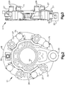
Fig. 2 is an end elevational view of the electric brake. -
Fig. 3 is a radial side elevational view of the electric brake. -
Fig. 4 is a perspective view of an actuator module used in the electric brake. -
Fig. 5 is a side elevational view of the actuator module. -
Fig. 6 is plan view of the actuator module. -
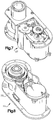
Fig. 7 is a perspective view of the actuator module with a bottom cover removed. -
Fig. 8 is another perspective view of the actuator module with a top cover removed. -
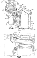
Fig. 9 is a cross-sectional view of the actuator module. -
Fig. 10 is a perspective view of the actuator module with parts of the housing broken away to reveal internal components. -
Fig. 11 is a perspective fragmentary rendering showing another mode of connectivity of an actuator module with a cable conduit according to the invention. - Because the invention was conceived and developed for use in an aircraft braking system, it will be herein described chiefly in this context. However, the principles of the invention in their broader aspects can be adapted to other types of braking systems, such as in train brake systems.
- Referring now in detail to the drawings and initially to
Figs. 1-3 , an electric brake according to the present invention is generally indicated at 10. Thebrake 10 generally comprises abrake actuator assembly 11 and a heat sink in the form of abrake disk stack 12. Thebrake disk stack 12 can be of a conventional design including stationary brake elements and rotary brake elements that are interleaved and surround a torque tube or equivalent (not shown). The stationary and rotary brake elements usually are in the form ofstator disks 15 androtor disks 16. Thestator disks 15 typically are splined to the torque tube and therotor disks 16 are splined to a wheel (not shown) interiorly of the wheel's rim. As is conventional, the splined connection may be effected by a plurality of spline or drive keys that are spaced around the circumference of the rim/torque tube to permit axial movement of the rotor/stator disks while being held to the wheel/torque tube against relative rotation. - The wheel (not shown) typically is supported for rotation on an axle (not shown) by axially spaced apart bearings (not shown). The axle thus forms a wheel mount and typically is attached to an aircraft landing gear strut or truck (not shown).
- The
brake actuator assembly 11 includes a brake head 18 (also commonly referred to as a brake housing) having acentral opening 19 for mounting of the brake head on the landing gear axle or other wheel support. For some applications the brake head can be formed integrally with or fixedly secured (as by splines, bolts, etc.) to the axle or other wheel support for direct transfer of braking torque to the axle or other wheel support. In the illustrated embodiment, the brake head is supported on the axle for limited rotational movement, and the brake head is provided with a torque take-outarm 20. The torque take-outarm 20 extends radially and functions as a torque transfer interface between the brake actuator assembly and the landing gear axle/strut/truck structure. More particularly, the torque take-outarm 20 has aneye 23 the provides for connection to a brake rod that in turn is connected to the landing gear axle/strut/truck structure, as in a conventional manner, to provide for transfer of torque from the torque take-out arm to the landing gear axle/strut/truck structure when braking force is being applied to thedisk brake stack 12 by thebrake actuator assembly 11. - The
disk stack 12 typically is located between a back pressure member (not shown) and thebrake head 18. The back pressure member can be formed by a radial flange at the end of the torque tube opposite the brake head, which radial flange engages the last brake disk at the outboard end of the disk stack typically through the use of a plurality of circumferentially spaced apart pucks. - Pressure is applied to the other or inboard end of the
disk stack 12 by theram 26 of one ormore actuator modules 27 that are mounted to thebrake head 18. Theactuator modules 27 preferably are mounted in a circular arrangement around the center axis of thebrake head 18, preferably with the actuator rams 26 generally circumferentially equally spaced apart or with the rams arranged in diametrically opposed pairs. In the illustrated preferred embodiment, theactuator modules 27 are each electrically connected to anelectrical cable conduit 29 that has asingle interface connector 30 to which a mating connector of a control cable (not shown) can be detachably connected for connecting thebrake 10 to a brake controller (not shown) located elsewhere. - Preferably, the
actuator modules 27 are identical and interchangeable, and a representative one of the actuator modules is shown inFigs. 4-10 . As best seen inFigs. 9 and10 , eachactuator module 27 preferably includes anelectric motor 31, agear train 32, a ball screw andnut assembly 33, and abi-stable holding brake 34. Themotor 31, gearing 32, ball screw andnut assembly 33, and holdingbrake 34 are all carried in amodule housing 36. In the illustrated embodiment, themodule housing 36 includes acase 39 having a top opening closed by atop cover 40 and a bottom opening closed by abottom cover 41. The openings provide for assembly of the various internal components of the actuator module in the module housing. - The
motor 31 can be of any suitable type, such as a brushless DC servo motor that may have integrated or otherwise associated therewith aresolver 42 for motor rotor commutation, angular velocity sensing and/or position sensing. The resolver can provide motor position feedback and velocity information. In particular, the resolver can provide an electrical signal that is proportional to motor shaft position under normal operating conditions. Power and control and/or output signals to or from the motor, resolver and holdingbrake 34 can be provided via an electrical connector 43 (Figs. 4-6 ), which in the illustrated embodiment is located on an inner side of the actuator module housing for connecting to a mating connector provided in thecable conduit 29. - The
gear train 32 provides for multiple stages of reduction. Afirst stage gear 44 meshes with agear 45 integral with thedrive shaft 46 of themotor 31. Thegear 44 meshes with agear 46 on ashaft 47 that has afurther gear 48 that meshes with agear 49 provided on ashaft 50. Thegear 49 also meshes with agear 51 provided on ashaft 52. Theshaft 52 has a further,gear 53 that meshes with ascrew drive gear 54 that preferably is formed integrally with theball screw 55 of the ball screw andnut assembly 33. The axes of the several shafts preferably are parallel with the axis of the ball screw and also theshaft 46 of the motor. Also, the shafts and ball screw are suitably journalled in the housing by suitable bearings for rotation about their respective axes, as is illustrated inFigs. 9 and10 . - In addition to the
ball screw 55, the ball screw andnut assembly 33 includesball nut 56 that moves linearly in response to rotation of the ball screw. It perhaps should be mentioned here that while a ball screw and nut are shown, other types of screw and nut assembly can be alternatively used, as can other types of rotary to linear motion conversion devices. Theball nut 56 is attached to or, as illustrated, formed as part of theactuator ram 26. The ball nut and thus also the ram are free to translate along the axis of theball screw 55 upon rotation of the ball screw, while, rotation of the ball nut is constrained. In the illustrated embodiment, rotation is constrained by interaction of the ball nut with aguideway 58 for the ram in themodule housing 36. - In the illustrated embodiment, the
guideway 58 is formed by a bore in thecasing 39 of thehousing 18. Thebore 39 has an innerlongitudinal portion 62 of non-circular cross-section for interacting with a non-circular cross-section of theram nut 56 to prevent rotation of the ram nut relative to the housing. By way of a preferred example, the cross-sections of the ball nut and inner portion of theguideway 58 can have corresponding hexagonal or other polygonal shapes. - As is preferred, the
ram nut 56 extends only partway along the linear extent of theram 26, whereas the outer orforward portion 64 of the ram is circular in cross-section. Similarly, the outer orforward portion 65 of theguideway 58 is circular in cross-section for guided movement of the cylindrical outer portion of the ram. The corresponding circular cross-sections are easier to seal than non-circular cross-sections. As shown, the guideway has at its outer end an annular groove for receiving a wiper or othersuitable seal 67 for preventing foreign matter from entering the module housing and/or for retaining lubricant with the module housing. As will be appreciated, the length of the non-circular inner portion of the guideway will be greater than the length of the ball nut to allow for linear movement of the ball nut. The length of the non-circular inner portion of the guideway will also determine the stroke of the ram. In the illustrated embodiment, the length of the circular outer portion of the guideway is about equal the length of the ram nut. The particular dimensions can be varied as desired for a given application. - Preferably, a lubricant, particularly a suitable grease, is used to lubricate the relatively sliding surfaces of the ball nut/ram and the
guideway 58. It has been found that the grease and close clearance between theball nut 56 andguideway 58 prevent entry of any appreciable amount of dirt or other foreign material at the sliding surfaces interface so as to prevent any significant degradation of performance. However, as above mentioned, asuitable seal 67, such as a wiper seal or a rolling diaphragm seal, is employed to seal against passage of dirt or other undesirable materials between the sliding surfaces. An exemplary grease for the ball screw and ram nut assembly is MIL-G-81322 and an exemplary grease for the gear train is MIL-G-81827. - As shown, the
ram 26 may be tubular and have its outer end closed by acap 70 screwed into the end of the bore in the ram or otherwise secured to the ram. The cap can also be used as a convenient means to attach an insulatingpad 71 to the end of the ram as depicted inFig. 3 , which pad provides the interface to the brake disk pressure plate and inhibits heat transfer into the actuator module. - As will be appreciated, rotation of the
motor 31 in one direction will effect extension of theram 26 for engaging and squeezing thebrake disk stack 12, whereas rotation in the opposite direction will effect retraction of the ram, as for releasing braking force. In any given position of the ram, the gear train can be locked by thebi-stable holding brake 34. This is desirable, for example, to retain the rams in an extended position applying braking force to the brake disk stack when the plane is parked, thereby to keep the brake engaged to prevent movement of the aircraft. Although other types of braking devices can be used to maintain the actuators in a brake-engaged condition, preferably the holding brake is a bi-stable device that will latch and hold in either on or off positions, even when no power is being applied to the brake. However, when pulsed the device can be switched between its on and off positions. A suitable bi-stable holding brake can be obtained from Electroid Company of Springfield, NJ, USA. and reference may be had toU.S. Patent No. 5,185,542 . - As shown in
Fig. 9 , the bi-stable holding brake can be coupled to theshaft 49 to permit or prevent rotation of theshaft 50 when the brake is on or off, respectively. - As seen in
Figs. 4-10 , a mountingflange 73 is provided on the housing for securing the module to thebrake head 18. As seen inFigs. 1 and2 , thebrake head 18 has a plurality of radially outwardly openingslots 75 at radially outer sides thereof for receivingrespective actuator modules 27. That is, the actuators can be inserted radially into and radially removed from the slots. Moreover, this can be done without having to remove thebrake disk stack 12. Accordingly, a defective actuator module can be swapped out without having to undergo any major disassembly of the overall brake assembly. - The mounting
flange 73 of eachmodule 27 preferably engages the surface of the brake head facing the brake stack. This surface can be provided with recesses 77 (Fig. 3 ) for receiving the flanges of the actuator modules, as may be desired to facilitate proper locating of the actuator modules in the brake head and alignment of holes for bolt or other fastening devices. Also, aheat shield 79 can be attached to the side of the brake head nearest the brake stack, which shield can be provided with opening for passage of the actuator rams. - The
connector 43 on eachactuator module 27 and the mating connector of thecable conduit 29 can be configured to provide for connection of the connectors when the actuator module is inserted radially into its respective slot in the brake head. To that end, the connectors can be oriented for radial insertion of one connector into the other connector. In an alternative configuration shown inFig. 11 , each module connector 43' andmating conduit connector 81 can be oriented axially. Accordingly, the actuator modules 27' are first installed, and then the cable conduit is pressed into place to mate theconnectors 81 thereof with the respective connectors 43' of the actuator modules. As is preferred, the cable conduit is a single line replacement unit which provides for all electrical connectivity to the actuator modules. The conduit can be formed by a base member having a channel that opens to one side of the base member. The cabling can be placed in the channel and then a cover can be secured to the base member to close the channel. Such securement can be effected by one or more threaded fasteners. The fasteners can be positioned such that when the conduit is installed to the brake head, the fasteners are covered by respective portions of the brake head, thereby to prevent the screws from falling out should they become loose. The conduit can be sealed to prevent entry of foreign material, and the external connectors can be of a type that when mated provide a hermetic seal. - Although the invention has been shown and described with respect to a certain preferred embodiment or embodiments, it is obvious that equivalent alterations and modifications will occur to others skilled in the art upon the reading and understanding of this specification and the annexed drawings, within the scope of the appended claims. In particular regard to the various functions performed by the above described integers (components, assemblies, devices, compositions, etc.), the terms (including a reference to a "means") used to describe such integers are intended to correspond, unless otherwise indicated, to any integer which performs the specified function of the described integer (i.e., that is functionally equivalent), even though not structurally equivalent to the disclosed structure which performs the function in the herein illustrated exemplary embodiment or embodiments of the invention. In addition, while a particular feature of the invention may have been described above with respect to only one of several illustrated embodiments, such feature may be combined with one or more other features of the other embodiments, as may be desired and advantageous for any given or particular application.
Claims (10)
- An electric brake actuator module (27), comprising:a module housing (18) having a guideway (58); anda reciprocating ram (26) axially movable in the guideway (58),wherein the ram (26) has an inner portion (56) of non-circular cross-section and an outer portion (64) of circular cross-section, andwherein the guideway (58) has an inner longitudinal portion (62) of non-circular cross-section for interacting with the inner portion of the ram (26) to prevent rotation of the inner portion of the ram (26) and to determine a stroke of the ram (26), and an outer portion (65) of circular cross-section sealed with respect to the outer portion of the ram (26).
- The electric brake actuator module according to claim 1, comprising:an electric motor (31) operatively connected to the reciprocating ram (26) for selectively extending and retracting the reciprocating ram (21) with respect to the module housing (18);wherein an axis of a shaft (46) of the electric motor (31) is parallel with an axis of the ram.
- The actuator module according to claim 1, comprising an annular seal (67) between the outer portion (64) of the ram and the outer portion (65) of the guideway.
- The actuator module according to claim 2, wherein the electric motor (31) is operatively connected to the ram (26) by a screw (55) and a nut (56) linearly driven by the screw (56), the inner portion (56) of the ram (26) including the nut (56).
- The actuator module according to claim 4, wherein the screw (55) and nut (56) are a ball screw (55) and a ball nut (56); the guideway (58) is formed by a bore in the housing (18); and the electric motor (31) is operatively connected to the screw (55) by reducing gears (32) carried on shafts mounted in the housing (18) for rotation about axes parallel to the rotational axes of the electric motor (31) and screw (55).
- The actuator module (27) according to claim 2, further comprising:
a bi-stable holding brake (34) having a first state permitting at least retraction of the ram (26) and a second state preventing at least retraction of the ram (26). - The actuator module (27) according to claim 2, wherein the reciprocating ram (26) has a movement direction, and the actuator module (27) further comprises:
an electrical connector (43) on the module housing (18), the electrical connector (43) having an insertion direction for connecting to a mating connector (81), and the insertion direction is parallel to the movement direction of the ram (26). - A brake comprising:a brake head (18); andat least one actuator module (27) according to claim 2 mounted to the brake head (18), wherein the electric motor (31) is operatively connected to the reciprocating ram (26) for selectively moving the reciprocating ram (26) into and out of forceful engagement with a brake disk stack (12) for applying and releasing braking force, wherein the module housing (18) carries the ram (26) and the electric motor (31) for removal from the brake head (18) as a unit; andwherein the brake head (18) has at least one radially outwardly opening slot at a radially outer side thereof for receiving said one actuator module (21).
- A brake comprising:a brake head (18); andat least one actuator module (27) according to claim 2 mounted to the brake head (18), wherein the electric motor (31) is operatively connected to a the reciprocating ram (26) for selectively moving the reciprocating ram (26) into and out of forceful engagement with a brake disk stack (12) for applying and releasing braking force, wherein the module housing (18)-carries the electric motor (31) for removal from the brake head (18) as a unit; andwherein the brake head (18) has at least one radially outwardly opening slot at a radially outer side thereof for receiving said one actuator module (21).
- A system comprising:a brake according to claim 8; anda cable conduit for the brake, comprising:a generally arcuate-shaped channel;a plurality of module connectors (43) disposed along the length of the channel for connecting to respective actuator modules (27) of the brake;a common connector disposed along the length of the channel for connecting to an external cable; andelectrical wiring in the channel for connecting the common connector to each of the module connectors.
Applications Claiming Priority (2)
| Application Number | Priority Date | Filing Date | Title |
|---|---|---|---|
| US46657903P | 2003-04-30 | 2003-04-30 | |
| PCT/US2004/013213 WO2005001303A2 (en) | 2003-04-30 | 2004-04-30 | Electric brake for aircraft |
Publications (2)
| Publication Number | Publication Date |
|---|---|
| EP1618313A2 EP1618313A2 (en) | 2006-01-25 |
| EP1618313B1 true EP1618313B1 (en) | 2020-12-02 |
Family
ID=33551402
Family Applications (1)
| Application Number | Title | Priority Date | Filing Date |
|---|---|---|---|
| EP04750885.8A Expired - Lifetime EP1618313B1 (en) | 2003-04-30 | 2004-04-30 | Electric brake for aircraft |
Country Status (3)
| Country | Link |
|---|---|
| US (1) | US7717240B2 (en) |
| EP (1) | EP1618313B1 (en) |
| WO (1) | WO2005001303A2 (en) |
Cited By (2)
| Publication number | Priority date | Publication date | Assignee | Title |
|---|---|---|---|---|
| EP4420942A1 (en) * | 2023-02-24 | 2024-08-28 | Goodrich Corporation | Brake assembly with electric brake actuators and method |
| EP4146537B1 (en) * | 2020-05-04 | 2024-10-30 | Safran Landing Systems | Heat shield for a braking device of an aircraft wheel |
Families Citing this family (21)
| Publication number | Priority date | Publication date | Assignee | Title |
|---|---|---|---|---|
| FR2862280B1 (en) * | 2003-11-14 | 2006-03-03 | Messier Bugatti | LANDING DEVICE, BRAKE FOR AIRCRAFT WHEEL, AIRCRAFT AIRBORNE WHEEL ASSEMBLY, AND METHOD OF MAINTAINING SUCH A LICENSOR |
| US7527129B2 (en) | 2004-08-31 | 2009-05-05 | Honeywell International Inc. | Brake carrier having improved electromechanical actuator and mounting arrangement therefor |
| US10252477B2 (en) * | 2009-08-26 | 2019-04-09 | Honeywell International Inc. | Mechanical assembly housing |
| US8919504B2 (en) | 2009-12-03 | 2014-12-30 | Honeywell International Inc. | Brake actuator assembly with line replaceable motor features |
| US9440735B2 (en) * | 2010-01-25 | 2016-09-13 | Honeywell International Inc. | Aircraft electric brake actuation system and method |
| US9815438B2 (en) * | 2010-02-12 | 2017-11-14 | Honeywell International Inc. | Aircraft electric brake actuator assembly with line replaceable actuator brake |
| US9061674B2 (en) * | 2012-10-24 | 2015-06-23 | Goodrich Corporation | Braking system and method of detecting a failure of a brake actuator |
| FR3003413B1 (en) * | 2013-03-12 | 2015-04-10 | Messier Bugatti Dowty | ELECTROMECHANICAL ACTUATOR FOR BRAKE |
| FR3013294B1 (en) | 2013-11-20 | 2017-04-21 | Messier Bugatti Dowty | ELECTROMECHANICAL ACTUATOR FOR A VEHICLE BRAKE AND A BRAKING SYSTEM COMPRISING SUCH ACTUATOR. |
| EP2921358B1 (en) * | 2014-03-21 | 2019-05-01 | IMS Gear SE & Co. KGaA | Actuator assembly |
| US9308990B2 (en) * | 2014-05-30 | 2016-04-12 | Goodrich Corporation | Voice coil linear activated park brake |
| US9995353B2 (en) * | 2015-12-21 | 2018-06-12 | Goodrich Corporation | Modified actuator design to improve load distribution and damping |
| US10584754B2 (en) * | 2017-09-19 | 2020-03-10 | Whippany Actuation Systems Llc | Line replaceable brake |
| US10458499B2 (en) * | 2017-10-20 | 2019-10-29 | Akebono Brake Industry Co., Ltd. | Multi-caliper brake assembly per rotor |
| CN108760107A (en) * | 2018-05-07 | 2018-11-06 | 西安航空制动科技有限公司 | A kind of force snesor in electric brake actuator |
| US11518353B2 (en) * | 2020-06-17 | 2022-12-06 | The Boeing Company | Systems and method for determining running clearance brake command for a brake system |
| KR102159186B1 (en) * | 2020-07-09 | 2020-09-23 | (주)대영엠텍 | Aircraft electric braking system |
| US11713794B2 (en) | 2020-08-21 | 2023-08-01 | Goodrich Corporation | Piston housing assembly |
| FR3117561B1 (en) * | 2020-12-10 | 2022-11-25 | Safran Landing Systems | Integrated parking brake actuator |
| CN115534915A (en) * | 2022-08-30 | 2022-12-30 | 万向钱潮(上海)汽车系统有限公司 | An electronic parking actuator |
| US20240270216A1 (en) * | 2023-02-10 | 2024-08-15 | Goodrich Corporation | Integrated actuator plate for ebrake |
Citations (3)
| Publication number | Priority date | Publication date | Assignee | Title |
|---|---|---|---|---|
| US4865162A (en) * | 1986-12-15 | 1989-09-12 | Opus Acquisition Corporation | Electrically actuated aircraft brakes |
| EP0831250A2 (en) * | 1996-09-24 | 1998-03-25 | Dana Corporation | Linear actuator |
| DE10128251A1 (en) * | 2000-09-04 | 2002-05-16 | Continental Teves Ag & Co Ohg | Actuating unit for an electromechanically actuated disc brake |
Family Cites Families (13)
| Publication number | Priority date | Publication date | Assignee | Title |
|---|---|---|---|---|
| US4567967A (en) * | 1979-07-30 | 1986-02-04 | Goodyear Aerospace Corporation | Electrically actuated aircraft brakes |
| US4596316A (en) * | 1984-02-10 | 1986-06-24 | Goodyear Aerospace Corporation | Electrically actuated aircraft brakes |
| US5185542A (en) * | 1991-08-28 | 1993-02-09 | Electroid Company | Electromagnetic pulse operated bi-stable brake |
| GB2290840A (en) * | 1994-06-01 | 1996-01-10 | Arthur Richard | Fail-safe brake actuation system |
| US5452948A (en) * | 1994-10-07 | 1995-09-26 | The Whitaker Corporation | Apparatus and method for electronically controlled hydraulic actuator |
| DE19621533A1 (en) * | 1996-05-29 | 1997-12-04 | Bosch Gmbh Robert | Electromotive brake device |
| DE19752543A1 (en) * | 1997-11-27 | 1999-06-02 | Bosch Gmbh Robert | Magnetic brake and electromechanical braking device with a magnetic brake |
| US6095293A (en) * | 1998-02-13 | 2000-08-01 | The B. F. Goodrich Company | Aircraft brake and method with electromechanical actuator modules |
| JP2000127934A (en) * | 1998-10-23 | 2000-05-09 | Unisia Jecs Corp | Hydraulic unit of anti-lock brake device |
| US6581730B1 (en) * | 1999-09-13 | 2003-06-24 | Goodrich Corporation | Aircraft landing gear with integrated brake actuation system |
| EP1214531B1 (en) * | 1999-09-13 | 2005-12-28 | Goodrich Corporation | Electric brake actuator module for aircraft |
| FR2813580B1 (en) | 2000-09-01 | 2002-12-20 | Labinal | BRAKING DEVICE FOR AN AIRCRAFT WHEEL |
| US7527129B2 (en) * | 2004-08-31 | 2009-05-05 | Honeywell International Inc. | Brake carrier having improved electromechanical actuator and mounting arrangement therefor |
-
2004
- 2004-04-30 EP EP04750885.8A patent/EP1618313B1/en not_active Expired - Lifetime
- 2004-04-30 WO PCT/US2004/013213 patent/WO2005001303A2/en not_active Ceased
- 2004-04-30 US US10/554,941 patent/US7717240B2/en active Active
Patent Citations (3)
| Publication number | Priority date | Publication date | Assignee | Title |
|---|---|---|---|---|
| US4865162A (en) * | 1986-12-15 | 1989-09-12 | Opus Acquisition Corporation | Electrically actuated aircraft brakes |
| EP0831250A2 (en) * | 1996-09-24 | 1998-03-25 | Dana Corporation | Linear actuator |
| DE10128251A1 (en) * | 2000-09-04 | 2002-05-16 | Continental Teves Ag & Co Ohg | Actuating unit for an electromechanically actuated disc brake |
Cited By (2)
| Publication number | Priority date | Publication date | Assignee | Title |
|---|---|---|---|---|
| EP4146537B1 (en) * | 2020-05-04 | 2024-10-30 | Safran Landing Systems | Heat shield for a braking device of an aircraft wheel |
| EP4420942A1 (en) * | 2023-02-24 | 2024-08-28 | Goodrich Corporation | Brake assembly with electric brake actuators and method |
Also Published As
| Publication number | Publication date |
|---|---|
| US20070187192A1 (en) | 2007-08-16 |
| US7717240B2 (en) | 2010-05-18 |
| WO2005001303A3 (en) | 2005-02-17 |
| WO2005001303A2 (en) | 2005-01-06 |
| EP1618313A2 (en) | 2006-01-25 |
Similar Documents
| Publication | Publication Date | Title |
|---|---|---|
| US7717240B2 (en) | Electric brake for aircraft | |
| CA2261506C (en) | Brake and method with electromechanical actuator modules | |
| CA2318688C (en) | Aircraft landing gear with integrated brake actuation system | |
| EP1766256B1 (en) | Electric brake for aircraft | |
| EP1214531B1 (en) | Electric brake actuator module for aircraft | |
| EP2060821A1 (en) | Aircraft brake and method with electromechanical actuator modules | |
| EP2147226B1 (en) | Repair of electric aircraft brake | |
| EP1214530B1 (en) | Integrated aircraft wheel, brake and axle for all-electric aircraft braking system | |
| EP3453612B1 (en) | Aircraft brake torque load reaction through landing gear bogie structure | |
| EP1384914B1 (en) | Electrically actuated disc brake assembly | |
| US20100276233A1 (en) | System to eliminate electric actuator contamination | |
| EP1626001A1 (en) | Multi-disc brake for aircraft | |
| US8794394B2 (en) | Electric brake system with flexible force transfer member |
Legal Events
| Date | Code | Title | Description |
|---|---|---|---|
| PUAI | Public reference made under article 153(3) epc to a published international application that has entered the european phase |
Free format text: ORIGINAL CODE: 0009012 |
|
| 17P | Request for examination filed |
Effective date: 20051104 |
|
| AK | Designated contracting states |
Kind code of ref document: A2 Designated state(s): AT BE BG CH CY CZ DE DK EE ES FI FR GB GR HU IE IT LI LU MC NL PL PT RO SE SI SK TR |
|
| AX | Request for extension of the european patent |
Extension state: AL HR LT LV MK |
|
| DAX | Request for extension of the european patent (deleted) | ||
| RBV | Designated contracting states (corrected) |
Designated state(s): DE FR GB |
|
| 17Q | First examination report despatched |
Effective date: 20100121 |
|
| STAA | Information on the status of an ep patent application or granted ep patent |
Free format text: STATUS: EXAMINATION IS IN PROGRESS |
|
| GRAP | Despatch of communication of intention to grant a patent |
Free format text: ORIGINAL CODE: EPIDOSNIGR1 |
|
| STAA | Information on the status of an ep patent application or granted ep patent |
Free format text: STATUS: GRANT OF PATENT IS INTENDED |
|
| INTG | Intention to grant announced |
Effective date: 20200618 |
|
| GRAS | Grant fee paid |
Free format text: ORIGINAL CODE: EPIDOSNIGR3 |
|
| GRAA | (expected) grant |
Free format text: ORIGINAL CODE: 0009210 |
|
| STAA | Information on the status of an ep patent application or granted ep patent |
Free format text: STATUS: THE PATENT HAS BEEN GRANTED |
|
| REG | Reference to a national code |
Ref country code: DE Ref legal event code: R081 Ref document number: 602004054875 Country of ref document: DE Owner name: GOODRICH CORP., CHARLOTTE, US Free format text: FORMER OWNER: GOODRICH CORP., CHARLOTTE, N.C., US |
|
| AK | Designated contracting states |
Kind code of ref document: B1 Designated state(s): DE FR GB |
|
| REG | Reference to a national code |
Ref country code: GB Ref legal event code: FG4D |
|
| REG | Reference to a national code |
Ref country code: DE Ref legal event code: R096 Ref document number: 602004054875 Country of ref document: DE |
|
| REG | Reference to a national code |
Ref country code: DE Ref legal event code: R097 Ref document number: 602004054875 Country of ref document: DE |
|
| PLBE | No opposition filed within time limit |
Free format text: ORIGINAL CODE: 0009261 |
|
| STAA | Information on the status of an ep patent application or granted ep patent |
Free format text: STATUS: NO OPPOSITION FILED WITHIN TIME LIMIT |
|
| 26N | No opposition filed |
Effective date: 20210903 |
|
| PGFP | Annual fee paid to national office [announced via postgrant information from national office to epo] |
Ref country code: FR Payment date: 20230321 Year of fee payment: 20 |
|
| PGFP | Annual fee paid to national office [announced via postgrant information from national office to epo] |
Ref country code: GB Payment date: 20230321 Year of fee payment: 20 |
|
| P01 | Opt-out of the competence of the unified patent court (upc) registered |
Effective date: 20230522 |
|
| PGFP | Annual fee paid to national office [announced via postgrant information from national office to epo] |
Ref country code: DE Payment date: 20230321 Year of fee payment: 20 |
|
| REG | Reference to a national code |
Ref country code: DE Ref legal event code: R071 Ref document number: 602004054875 Country of ref document: DE |
|
| REG | Reference to a national code |
Ref country code: GB Ref legal event code: PE20 Expiry date: 20240429 |
|
| PG25 | Lapsed in a contracting state [announced via postgrant information from national office to epo] |
Ref country code: GB Free format text: LAPSE BECAUSE OF EXPIRATION OF PROTECTION Effective date: 20240429 |
|
| PG25 | Lapsed in a contracting state [announced via postgrant information from national office to epo] |
Ref country code: GB Free format text: LAPSE BECAUSE OF EXPIRATION OF PROTECTION Effective date: 20240429 |