EP1617145A2 - Cooling aft end of a combustion liner - Google Patents
Cooling aft end of a combustion liner Download PDFInfo
- Publication number
- EP1617145A2 EP1617145A2 EP05254276A EP05254276A EP1617145A2 EP 1617145 A2 EP1617145 A2 EP 1617145A2 EP 05254276 A EP05254276 A EP 05254276A EP 05254276 A EP05254276 A EP 05254276A EP 1617145 A2 EP1617145 A2 EP 1617145A2
- Authority
- EP
- European Patent Office
- Prior art keywords
- liner
- air
- transition region
- channels
- combustion
- Prior art date
- Legal status (The legal status is an assumption and is not a legal conclusion. Google has not performed a legal analysis and makes no representation as to the accuracy of the status listed.)
- Withdrawn
Links
Images

Classifications
-
- F—MECHANICAL ENGINEERING; LIGHTING; HEATING; WEAPONS; BLASTING
- F23—COMBUSTION APPARATUS; COMBUSTION PROCESSES
- F23R—GENERATING COMBUSTION PRODUCTS OF HIGH PRESSURE OR HIGH VELOCITY, e.g. GAS-TURBINE COMBUSTION CHAMBERS
- F23R3/00—Continuous combustion chambers using liquid or gaseous fuel
- F23R3/002—Wall structures
-
- F—MECHANICAL ENGINEERING; LIGHTING; HEATING; WEAPONS; BLASTING
- F23—COMBUSTION APPARATUS; COMBUSTION PROCESSES
- F23R—GENERATING COMBUSTION PRODUCTS OF HIGH PRESSURE OR HIGH VELOCITY, e.g. GAS-TURBINE COMBUSTION CHAMBERS
- F23R3/00—Continuous combustion chambers using liquid or gaseous fuel
- F23R3/02—Continuous combustion chambers using liquid or gaseous fuel characterised by the air-flow or gas-flow configuration
- F23R3/04—Air inlet arrangements
-
- F—MECHANICAL ENGINEERING; LIGHTING; HEATING; WEAPONS; BLASTING
- F23—COMBUSTION APPARATUS; COMBUSTION PROCESSES
- F23R—GENERATING COMBUSTION PRODUCTS OF HIGH PRESSURE OR HIGH VELOCITY, e.g. GAS-TURBINE COMBUSTION CHAMBERS
- F23R2900/00—Special features of, or arrangements for continuous combustion chambers; Combustion processes therefor
- F23R2900/03042—Film cooled combustion chamber walls or domes
-
- F—MECHANICAL ENGINEERING; LIGHTING; HEATING; WEAPONS; BLASTING
- F23—COMBUSTION APPARATUS; COMBUSTION PROCESSES
- F23R—GENERATING COMBUSTION PRODUCTS OF HIGH PRESSURE OR HIGH VELOCITY, e.g. GAS-TURBINE COMBUSTION CHAMBERS
- F23R2900/00—Special features of, or arrangements for continuous combustion chambers; Combustion processes therefor
- F23R2900/03043—Convection cooled combustion chamber walls with means for guiding the cooling air flow
Definitions
- This invention relates to internal cooling within a gas turbine engine; and more particularly, to apparatus providing better and more uniform cooling in a transition region between a combustion section and discharge section of the turbine.
- the apparatus which comprises a liner of an improved design, minimizes thermal stresses in the region, while increasing the effectiveness of cooling in the region, reduces the amount of cooling air required in this portion of the turbine. This allows more air to be directed the combustion section of the turbine which improves combustion of fuel and reduces emissions (NOx).
- a gas turbine engine has an air inlet section, a fuel combustion section, and an aft discharge section. There is a transition region between the combustion section of the turbine and the discharge section.
- a generally cylindrical liner is installed in this transition region and has openings formed therein through which cooling air is introduced into and flows through the liner to control the temperature in the transition region.
- the hot gas air temperature at the upstream, inlet portion of the liner (the outlet from the combustion section of the turbine), is on the order of 2800-3000°F.
- the target metal temperature is on the order of 1400-1550°F.
- the aft end of the liner is cooled by a plurality of uniform geometry cold side axial channels that flow air, at the turbine's compressor discharge temperature, over the liner's aft end. This produces convective cooling.
- a limitation with this geometry is that the resultant cooling has been found to be non-uniform with a substantial metal temperature gradient between one section of the liner and another. Overcoming this limitation has heretofore required increasing the quantity of cooling air flowed into passages of the liner in order to achieve an adequate level of cooling.
- the resulting increased airflow to and through the liner means that air which could otherwise be directed to the combustion section of the turbine, to aid in the combustion and reduce emissions, particularly NOx emissions, must instead be diverted to the aft end of the turbine to help keep the liner temperature within permissible bounds.
- the present invention is directed to an improved liner construction for enhancing the cooling in the transition region of a turbine engine between its combustion and discharge sections.
- the improvement of the invention comprises a liner having a plurality of airflow or cooling channels whose cross-section varies along the axial length of the liner. That is, the height of the channel decreases along the axial length of the liner from an air inlet to an air outlet of the liner's cooling channel. In one embodiment of the invention, the height of the channel is reduced by as much as approximately 60% from the inlet to the outlet end of each axial channel. Decreasing the height of the airflow channel in this way varies the cooling effect of air flowing through the channel in such a way as to result in more uniform metal temperatures. Importantly, this reduces thermal stresses, particularly at the aft, air outlet end of the liner.
- Optimizing the cooling of the aft end of the liner has significant advantages over current liner constructions.
- a particular advantage is that because of the improvement in cooling with the new liner, less air is required to flow through the liner to achieve desired liner metal temperatures; and, there is a balancing of the local velocity of air in the liner passage with the local temperature of the air.
- This provides a constant cooling heat flux along the length of the liner channel. As a result of this, there are reduced thermal gradients and thermal stresses within the liner.
- the reduced cooling air requirements also help prolong the service life of the liner due to reduced combustion reaction temperatures.
- the reduced airflow requirements allow more air to be directed to the combustion section of the turbine to improve combustion and reduce turbine emissions.
- a turbine engine is indicated generally 10 in Fig. 1.
- Engine 10 has a combustion section 12 where air drawn into the engine is combusted with a fuel.
- the engine further includes a discharge section 14.
- Hot gases from the combustion in section 12 flow from section 12 into section 14.
- the hot gas temperatures at the aft end of section 12, the inlet portion of region 16, is on the order of 2800°-3000°F.
- the liner metal temperature at the downstream, outlet portion of region 16 is preferably on the order of 1400°-1550°F.
- a liner 18 is provided through which cooling air is flowed. The cooling air serves to draw off heat from the liner and thereby significantly lower the liner metal temperature relative to that of the hot gases.
- Liner 18 has an associated compression-type seal 20, commonly referred to as a hula seal, mounted between a cover plate 22 (see Fig. 3) of the liner, and a portion of transition region 16.
- the cover plate is mounted on the liner to form a mounting surface for the compression seal and to form a portion of the axial airflow channels C.
- liner 18 has a plurality of axial channels formed with a plurality of axial raised sections or ribs 24 all of which extend over a portion of aft end of the liner.
- the cover plate 22 and ribs 24 together define the respective airflow channels C. These channels are parallel channels extending over a portion of aft end of liner 18. Cooling air is introduced into the channels through air inlet slots or openings 26 at the forward end of the channel. The air then flows into and through the channels C and exits the liner through openings 28 at an aft end 30 of the liner.
- the design of liner 18 is such as to minimize cooling air flow requirements, while still providing for sufficient heat transfer at aft end 30 of the liner, so to produce a uniform metal temperature along the liner. It will be understood by those skilled in the art that the combustion occurring within section 12 of the turbine results in a hot-side heat transfer coefficient and gas temperatures on an inner surface of liner 18. Outer surface (aft end) cooling of current design liners is now required so metal temperatures and thermal stresses to which the aft end of the liner is subjected remain within acceptable limits. Otherwise, damage to the liner resulting from excessive stress, temperature, or both, significantly shortens the useful life of the liner.
- Liner 18 of the present invention utilizes existing static pressure gradients occurring between the coolant outer side, and hot gas inner side, of the liner to affect cooling at the aft end of the liner. This is achieved by balancing the airflow velocity in liner channels C with the temperature of the air so to produce a constant cooling effect along the length of the channels and the liner.
- a prior art liner indicated generally 100, has a flow metering hole 102 extending across the forward end of the cover plate.
- the cross-section of the channel is constant along the entire length of the channel. This thickness is, for example, 0.045" (0.11cm).
- liner 18 of the present invention has a channel height which is substantially (approximately 45%) greater than the channel height of liner 100 at inlet 26 to the channel.
- this height steadily and uniformly decreases along the length of channel C so that, at the aft end of the channel, the channel height is substantially (approximately 55%) less than exit height of prior art liner 100.
- Liner 18 has, for example, an entrance channel height of 0.065" (0.16cm) and an exit height of, for example, 0.025" (0.06cm), so the height of the channel decreases by slightly more than 60% from the inlet end to the outlet end of the channel.
- Liner 18 therefore has the advantage of producing a more uniform axial thermal gradient, and reduced thermal stresses within the liner. This, in turn, results in an increased useful service life for the liner. As importantly, the requirement for cooling air to flow through the liner is now substantially reduced, and this air can be routed to combustion stage 12 of the turbine to improve combustion and reduce exhaust emissions, particularly NOx emissions.
- Fig. 4 is a comparison of the respective backside heat transfer coefficients at the aft end of prior art liner 100 and liner 18 of the present invention based upon the results from the studies.
- Fig. 4 by uniformly reducing the height of channels C in liner 18 along the length of the liner, heat transfer characteristics are now more uniform, although of relatively the same magnitude as with liner 100.
- the reduced plenum feed required by liner 18 provides maximum cold-side coverage, and there are no areas of poor cooling.
- the aft end of liner 18 exhibits a significant reduction in thermal strain when compared with the aft end of liner 100.
- Fig. 5 represents the metal temperatures within prior art liner 100 and liner 18 of the present invention.
- the hot side of each liner is subject to a gas temperature of 2750°F.
- liner 18 exhibits more uniform metal temperatures than liner 100.
- the increase in metal temperature at the aft end of liner 18 is an acceptable performance condition for the typical thermal strains experienced at this end of the liner.
- liner 18 of the present invention in which the height of the liner uniformly tapers along the length of the liner, the level of thermal strain at the liner's aft end is acceptable. Again, this not only helps promote the service life of the liner but also allows a portion of the airflow that previously had to be directed through the liner to now be routed to combustion section 12 of the turbine to improve combustion and reduce emissions.
Landscapes
- Engineering & Computer Science (AREA)
- Chemical & Material Sciences (AREA)
- Combustion & Propulsion (AREA)
- Mechanical Engineering (AREA)
- General Engineering & Computer Science (AREA)
- Turbine Rotor Nozzle Sealing (AREA)
Abstract
A liner (18) installed in a transition region between a combustion section of a gas turbine engine and an air discharge section of the turbine. The liner has an air inlet (26) for admitting air into the liner, and an air outlet (28) by which air is discharged from the liner. Flow of air through the liner acts to cool air flowing through the transition region of the turbine between the combustion and air discharge sections thereof, so to lower the liner metal temperature from hot gas temperatures resulting from combustion reaction to metal temperatures consistent with useful part life. The liner has a plurality of axial channel (C) formed in it for flow of air through the liner. The cross-sectional of the channels uniformly decrease along the length of each channel from the channel's air inlet to its air outlet. This liner construction reduces the thermal strain occurring at the aft end of the liner, prolonging the useful life of the liner, while reducing the amount of air needed to flow through the liner to affect a desired level of cooling in the transition region.
Description
- This invention relates to internal cooling within a gas turbine engine; and more particularly, to apparatus providing better and more uniform cooling in a transition region between a combustion section and discharge section of the turbine. The apparatus, which comprises a liner of an improved design, minimizes thermal stresses in the region, while increasing the effectiveness of cooling in the region, reduces the amount of cooling air required in this portion of the turbine. This allows more air to be directed the combustion section of the turbine which improves combustion of fuel and reduces emissions (NOx).
- A gas turbine engine has an air inlet section, a fuel combustion section, and an aft discharge section. There is a transition region between the combustion section of the turbine and the discharge section. A generally cylindrical liner is installed in this transition region and has openings formed therein through which cooling air is introduced into and flows through the liner to control the temperature in the transition region. The hot gas air temperature at the upstream, inlet portion of the liner (the outlet from the combustion section of the turbine), is on the order of 2800-3000°F. At the downstream, outlet portion of the liner, the target metal temperature is on the order of 1400-1550°F.
- Currently, the aft end of the liner is cooled by a plurality of uniform geometry cold side axial channels that flow air, at the turbine's compressor discharge temperature, over the liner's aft end. This produces convective cooling. A limitation with this geometry is that the resultant cooling has been found to be non-uniform with a substantial metal temperature gradient between one section of the liner and another. Overcoming this limitation has heretofore required increasing the quantity of cooling air flowed into passages of the liner in order to achieve an adequate level of cooling. The resulting increased airflow to and through the liner means that air which could otherwise be directed to the combustion section of the turbine, to aid in the combustion and reduce emissions, particularly NOx emissions, must instead be diverted to the aft end of the turbine to help keep the liner temperature within permissible bounds.
- Briefly stated, the present invention is directed to an improved liner construction for enhancing the cooling in the transition region of a turbine engine between its combustion and discharge sections. The improvement of the invention comprises a liner having a plurality of airflow or cooling channels whose cross-section varies along the axial length of the liner. That is, the height of the channel decreases along the axial length of the liner from an air inlet to an air outlet of the liner's cooling channel. In one embodiment of the invention, the height of the channel is reduced by as much as approximately 60% from the inlet to the outlet end of each axial channel. Decreasing the height of the airflow channel in this way varies the cooling effect of air flowing through the channel in such a way as to result in more uniform metal temperatures. Importantly, this reduces thermal stresses, particularly at the aft, air outlet end of the liner.
- Optimizing the cooling of the aft end of the liner has significant advantages over current liner constructions. A particular advantage is that because of the improvement in cooling with the new liner, less air is required to flow through the liner to achieve desired liner metal temperatures; and, there is a balancing of the local velocity of air in the liner passage with the local temperature of the air. This provides a constant cooling heat flux along the length of the liner channel. As a result of this, there are reduced thermal gradients and thermal stresses within the liner. The reduced cooling air requirements also help prolong the service life of the liner due to reduced combustion reaction temperatures. Finally, the reduced airflow requirements allow more air to be directed to the combustion section of the turbine to improve combustion and reduce turbine emissions.
- Embodiments of the invention will now be described, by way of example, with reference to the accompanying drawings, in which:
- Fig. 1 is a sectional view of a turbine engine illustrating a transition region between combustion and compressor air discharge sections of the turbine;
- Fig. 2 is an elevation view of a prior art aft liner region and an aft liner region of the present invention for flowing cooling air through a plurality of channels in a transition region of the turbine;
- Fig. 3 is an exploded view of a liner aft end of the present invention;
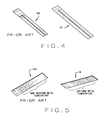
- Fig. 4 is a plan view of an aft end of a prior art liner and liner of the present invention illustrating relative differences in heat transfer coefficients between the two constructions; and,
- Fig. 5 is a plan view of the aft end of a prior art liner and liner of the present invention illustrating the relative differences in predicted metal temperatures between the two constructions.
- Corresponding reference numerals indicate corresponding parts throughout the several figures of the drawings.
- The following detailed description illustrates the invention by way of example and not by way of limitation. The description clearly enables one skilled in the art to make and use the invention, describes several embodiments, adaptations, variations, alternatives, and uses of the invention, including what is presently believed to be the best mode of carrying out the invention.
- Referring to the drawings, a turbine engine is indicated generally 10 in Fig. 1.
Engine 10 has acombustion section 12 where air drawn into the engine is combusted with a fuel. The engine further includes adischarge section 14. Hot gases from the combustion insection 12 flow fromsection 12 intosection 14. There is a transition region indicated generally 16 between these two sections. As previously noted, the hot gas temperatures at the aft end ofsection 12, the inlet portion ofregion 16, is on the order of 2800°-3000°F. However, the liner metal temperature at the downstream, outlet portion ofregion 16 is preferably on the order of 1400°-1550°F. To help cool the liner to this lower metal temperature range, during passage of heated gases throughregion 16, aliner 18 is provided through which cooling air is flowed. The cooling air serves to draw off heat from the liner and thereby significantly lower the liner metal temperature relative to that of the hot gases. -
Liner 18 has an associated compression-type seal 20, commonly referred to as a hula seal, mounted between a cover plate 22 (see Fig. 3) of the liner, and a portion oftransition region 16. The cover plate is mounted on the liner to form a mounting surface for the compression seal and to form a portion of the axial airflow channels C. As shown in Fig. 3,liner 18 has a plurality of axial channels formed with a plurality of axial raised sections orribs 24 all of which extend over a portion of aft end of the liner. Thecover plate 22 andribs 24 together define the respective airflow channels C. These channels are parallel channels extending over a portion of aft end ofliner 18. Cooling air is introduced into the channels through air inlet slots oropenings 26 at the forward end of the channel. The air then flows into and through the channels C and exits the liner throughopenings 28 at anaft end 30 of the liner. - In accordance with the invention, the design of
liner 18 is such as to minimize cooling air flow requirements, while still providing for sufficient heat transfer ataft end 30 of the liner, so to produce a uniform metal temperature along the liner. It will be understood by those skilled in the art that the combustion occurring withinsection 12 of the turbine results in a hot-side heat transfer coefficient and gas temperatures on an inner surface ofliner 18. Outer surface (aft end) cooling of current design liners is now required so metal temperatures and thermal stresses to which the aft end of the liner is subjected remain within acceptable limits. Otherwise, damage to the liner resulting from excessive stress, temperature, or both, significantly shortens the useful life of the liner. -
Liner 18 of the present invention utilizes existing static pressure gradients occurring between the coolant outer side, and hot gas inner side, of the liner to affect cooling at the aft end of the liner. This is achieved by balancing the airflow velocity in liner channels C with the temperature of the air so to produce a constant cooling effect along the length of the channels and the liner. - As shown in Fig. 2, a prior art liner, indicated generally 100, has a
flow metering hole 102 extending across the forward end of the cover plate. As indicated by the dotted lines extending the length ofliner 100, the cross-section of the channel, as defined by its height, is constant along the entire length of the channel. This thickness is, for example, 0.045" (0.11cm). - In contrast,
liner 18 of the present invention has a channel height which is substantially (approximately 45%) greater than the channel height ofliner 100 atinlet 26 to the channel. However, this height steadily and uniformly decreases along the length of channel C so that, at the aft end of the channel, the channel height is substantially (approximately 55%) less than exit height ofprior art liner 100.Liner 18 has, for example, an entrance channel height of 0.065" (0.16cm) and an exit height of, for example, 0.025" (0.06cm), so the height of the channel decreases by slightly more than 60% from the inlet end to the outlet end of the channel. - In comparing
prior art liner 100 withliner 18 of the present invention, it has been found that reducing the height of the channels (not shown) inliner 100, in order to match the cooling flow ofliner 18, will not provide sufficient cooling to produce acceptable metal temperatures inliner 100, nor does it effectively change; i.e., minimize, the flow requirement for cooling air through the liner. Rather, it has been found that providing a variable cooling passage height withinliner 18 optimizes the cooling ataft end 28 of the liner. With a variable channel height, optimal cooling is achieved because the local air velocity in the channel is now balanced with the local temperature of the cooling air flowing through the channel. That is, because the channel height is gradually reduced along the length of each channel, the cross-sectional area of the channel is similarly reduced. This results in an increase in the velocity of the cooling air flowing through channels C and can produce a more constant cooling heat flux along the entire length of each channel.Liner 18 therefore has the advantage of producing a more uniform axial thermal gradient, and reduced thermal stresses within the liner. This, in turn, results in an increased useful service life for the liner. As importantly, the requirement for cooling air to flow through the liner is now substantially reduced, and this air can be routed tocombustion stage 12 of the turbine to improve combustion and reduce exhaust emissions, particularly NOx emissions. - A series of CFD studies were performed using on design model of
liner 18 with boundary conditions assumed to be those of a 6FA+e combustion system under base load conditions. Results of the studies indicate that, under normal operating conditions, the design ofliner 18 provides sufficient cooling to the backside of the combustion liner. Predicted metal temperatures directly belowair inlet slot 26 indicate significant reduction in metal temperature variations. The results also indicate approximately a 50% reduction in cooling airflow requirements to maintain equivalent trailing edge life projections. - Fig. 4 is a comparison of the respective backside heat transfer coefficients at the aft end of
prior art liner 100 andliner 18 of the present invention based upon the results from the studies. As shown in Fig. 4, by uniformly reducing the height of channels C inliner 18 along the length of the liner, heat transfer characteristics are now more uniform, although of relatively the same magnitude as withliner 100. In addition, the reduced plenum feed required byliner 18 provides maximum cold-side coverage, and there are no areas of poor cooling. As a result, the aft end ofliner 18 exhibits a significant reduction in thermal strain when compared with the aft end ofliner 100. - Finally, Fig. 5 represents the metal temperatures within
prior art liner 100 andliner 18 of the present invention. Using boundary conditions at for a base load onturbine 10, the hot side of each liner is subject to a gas temperature of 2750°F. However, as shown in Fig. 5,liner 18 exhibits more uniform metal temperatures thanliner 100. The increase in metal temperature at the aft end of liner 18 (as compared to that at the aft end of liner 100) is an acceptable performance condition for the typical thermal strains experienced at this end of the liner. As noted above, it has been found that merely reducing the channel height in aliner 100, to reduce airflow through the liner, will not produce acceptable thermal strains at these increased metal temperatures. Withliner 18 of the present invention, in which the height of the liner uniformly tapers along the length of the liner, the level of thermal strain at the liner's aft end is acceptable. Again, this not only helps promote the service life of the liner but also allows a portion of the airflow that previously had to be directed through the liner to now be routed tocombustion section 12 of the turbine to improve combustion and reduce emissions.
Claims (10)
- A liner (18) adapted for installation in a transition region (16) between a combustion section (12) and an air discharge section (14) of an engine, comprising:a plurality of axial channels (C) extending over a portion of an aft end portion the liner parallel to each other, the cross-sectional area of each channel varying along the length of the channel; and,an air inlet (26) for admitting air into each channel and an air outlet (28) by which air is discharged from the liner, flow of air through the channels serving to cool the transition region of the engine between the combustion and air discharge sections thereof.
- The liner of claim 1 in which the cross-sectional area of each channel uniformly decreases along the length of the liner from the air inlet end to the air outlet end of the liner.
- The liner of claim 2 in which the height of the channel uniformly decreases along the length of the liner from the air inlet end to the air outlet end of the liner, thereby to reduce thermal strain occurring at the aft end of the liner so to prolong the useful life of the liner and reduce the amount of air needed to flow through the liner to affect a desired level of cooling in the transition region.
- The liner of claim 3 in which the height of the channels substantially decreases from the air inlet end to the air outlet end of the liner.
- The liner of claim 4 in which the height of the channels decreases by at least 40% from the air inlet end to the air outlet end of the liner.
- The liner of claim 1 which reduces the airflow through the liner required to lower the temperature in the transition region to a predetermined range of temperatures, this allowing an increased flow of air to the combustion section of the engine to improve combustion and reduce emissions.
- A turbine engine (10) comprising:a combustion section (12);an air discharge section (14) downstream of the combustion section;a transition region (16) between the sections; and,a liner (18) having an air inlet (26) for admitting air into the liner, an air outlet (28) by which air is discharged from the liner, flow of air through the liner serving to cool air flowing through the transition region of the engine between the combustion and air discharge sections thereof, and a plurality of channels (C) extending parallel to each other the length of the liner for flow of air through the liner, the cross-sectional area of the channels decreasing along the length of the liner from the air inlet end to the air outlet end thereof, thereby to reduce thermal strain occurring at the aft end of the liner so to prolong the useful life of the liner and reduce the amount of air needed to flow through the liner to affect a desired level of cooling in the transition region.
- The engine of claim 7 in which the height of the channels uniformly tapers along the length of the liner channels.
- The engine of claim 8 in which the height of the channels decreases by at least 40% from the air inlet end to the air outlet end of the liner.
- The engine of claim 7 which reduces the airflow through the liner required to lower the temperature in the transition region to a predetermined range of temperatures by at least 30%, this allowing an increased flow of air to the combustion section of the turbine to improve combustion and reduce emissions.
Applications Claiming Priority (1)
| Application Number | Priority Date | Filing Date | Title |
|---|---|---|---|
| US10/891,966 US20060010874A1 (en) | 2004-07-15 | 2004-07-15 | Cooling aft end of a combustion liner |
Publications (1)
| Publication Number | Publication Date |
|---|---|
| EP1617145A2 true EP1617145A2 (en) | 2006-01-18 |
Family
ID=35058824
Family Applications (1)
| Application Number | Title | Priority Date | Filing Date |
|---|---|---|---|
| EP05254276A Withdrawn EP1617145A2 (en) | 2004-07-15 | 2005-07-07 | Cooling aft end of a combustion liner |
Country Status (4)
| Country | Link |
|---|---|
| US (1) | US20060010874A1 (en) |
| EP (1) | EP1617145A2 (en) |
| JP (1) | JP2006029334A (en) |
| CN (1) | CN1721670A (en) |
Cited By (3)
| Publication number | Priority date | Publication date | Assignee | Title |
|---|---|---|---|---|
| EP2144003A3 (en) * | 2008-07-10 | 2014-02-12 | United Technologies Corporation | A combustion liner for a gas turbine engine |
| CN111853855A (en) * | 2020-06-18 | 2020-10-30 | 中国航发湖南动力机械研究所 | Gas turbine engine combustor |
| DE102009026052B4 (en) | 2008-07-07 | 2022-11-17 | General Electric Co. | Cooling device for the aft end of a combustor transition piece and associated method |
Families Citing this family (10)
| Publication number | Priority date | Publication date | Assignee | Title |
|---|---|---|---|---|
| JP2008274774A (en) * | 2007-04-25 | 2008-11-13 | Mitsubishi Heavy Ind Ltd | Gas turbine combustor and gas turbine |
| JP4831835B2 (en) * | 2007-09-25 | 2011-12-07 | 三菱重工業株式会社 | Gas turbine combustor |
| US20090120093A1 (en) * | 2007-09-28 | 2009-05-14 | General Electric Company | Turbulated aft-end liner assembly and cooling method |
| US8544277B2 (en) * | 2007-09-28 | 2013-10-01 | General Electric Company | Turbulated aft-end liner assembly and cooling method |
| US8673234B2 (en) * | 2008-03-04 | 2014-03-18 | Aerojet Rocketdyne Of De, Inc. | Reactor vessel and liner |
| US8549861B2 (en) * | 2009-01-07 | 2013-10-08 | General Electric Company | Method and apparatus to enhance transition duct cooling in a gas turbine engine |
| US7926283B2 (en) * | 2009-02-26 | 2011-04-19 | General Electric Company | Gas turbine combustion system cooling arrangement |
| JP5281685B2 (en) * | 2011-10-31 | 2013-09-04 | 三菱重工業株式会社 | Gas turbine combustor and gas turbine |
| US11859818B2 (en) * | 2019-02-25 | 2024-01-02 | General Electric Company | Systems and methods for variable microchannel combustor liner cooling |
| CN113074387B (en) * | 2021-04-29 | 2022-02-25 | 北京航空航天大学 | Regenerative cooling channel with truss structure |
Family Cites Families (6)
| Publication number | Priority date | Publication date | Assignee | Title |
|---|---|---|---|---|
| US3572031A (en) * | 1969-07-11 | 1971-03-23 | United Aircraft Corp | Variable area cooling passages for gas turbine burners |
| US3706203A (en) * | 1970-10-30 | 1972-12-19 | United Aircraft Corp | Wall structure for a gas turbine engine |
| US4719748A (en) * | 1985-05-14 | 1988-01-19 | General Electric Company | Impingement cooled transition duct |
| DE4222391C2 (en) * | 1992-07-08 | 1995-04-20 | Gutehoffnungshuette Man | Cylindrical combustion chamber housing of a gas turbine |
| US5724816A (en) * | 1996-04-10 | 1998-03-10 | General Electric Company | Combustor for a gas turbine with cooling structure |
| US7010921B2 (en) * | 2004-06-01 | 2006-03-14 | General Electric Company | Method and apparatus for cooling combustor liner and transition piece of a gas turbine |
-
2004
- 2004-07-15 US US10/891,966 patent/US20060010874A1/en not_active Abandoned
-
2005
- 2005-07-07 EP EP05254276A patent/EP1617145A2/en not_active Withdrawn
- 2005-07-14 JP JP2005205081A patent/JP2006029334A/en not_active Withdrawn
- 2005-07-15 CN CNA2005100844379A patent/CN1721670A/en active Pending
Cited By (3)
| Publication number | Priority date | Publication date | Assignee | Title |
|---|---|---|---|---|
| DE102009026052B4 (en) | 2008-07-07 | 2022-11-17 | General Electric Co. | Cooling device for the aft end of a combustor transition piece and associated method |
| EP2144003A3 (en) * | 2008-07-10 | 2014-02-12 | United Technologies Corporation | A combustion liner for a gas turbine engine |
| CN111853855A (en) * | 2020-06-18 | 2020-10-30 | 中国航发湖南动力机械研究所 | Gas turbine engine combustor |
Also Published As
| Publication number | Publication date |
|---|---|
| US20060010874A1 (en) | 2006-01-19 |
| JP2006029334A (en) | 2006-02-02 |
| CN1721670A (en) | 2006-01-18 |
Similar Documents
| Publication | Publication Date | Title |
|---|---|---|
| EP1617145A2 (en) | Cooling aft end of a combustion liner | |
| CN1704573B (en) | Apparatus for cooling combustor liner and transition piece of a gas turbine | |
| EP2211105A2 (en) | Turbulated combustor aft-end liner assembly and related cooling method | |
| US4805397A (en) | Combustion chamber structure for a turbojet engine | |
| JP4162855B2 (en) | Turbine engine that directs cooled P3 air to the rear cavity of the impeller | |
| CN101113820B (en) | Combustor liner with film cooling | |
| US8181443B2 (en) | Heat exchanger to cool turbine air cooling flow | |
| EP0284819B1 (en) | Gas turbine combustor transition duct forced convection cooling | |
| US20090120093A1 (en) | Turbulated aft-end liner assembly and cooling method | |
| US20130152591A1 (en) | System of integrating baffles for enhanced cooling of cmc liners | |
| US20110120135A1 (en) | Turbulated aft-end liner assembly and cooling method | |
| US7581385B2 (en) | Metering sheet and iso-grid arrangement for a non axi-symmetric shaped cooling liner within a gas turbine engine exhaust duct | |
| US20120269649A1 (en) | Turbine blade with improved trailing edge cooling | |
| EP2375160A2 (en) | Angled seal cooling system | |
| JP2018141460A (en) | Mounting bracket for fan casing and oil cooler | |
| US8413449B2 (en) | Gas turbine having an improved cooling architecture | |
| JPH08284688A (en) | Gas turbine and gas turbine combustion device | |
| JP2008309059A (en) | Cooling structure of turbine casing | |
| US20110214431A1 (en) | Turbine guide vane support for a gas turbine and method for operating a gas turbine | |
| US20200056504A1 (en) | Mounting portion for an exhaust gas turbocharger, and exhaust gas turbocharger | |
| CN117570471B (en) | Impact cooling integrated combustion chamber flame tube cooling wall structure and flame tube | |
| CN120331906A (en) | A turbine guide installation edge insulation structure | |
| JPS62111132A (en) | Gas turbine combustor tail tube cooling structure | |
| JPH07332113A (en) | Gas turbine and gas turbine combustion device | |
| JP2512256B2 (en) | Gas turbine combustor |
Legal Events
| Date | Code | Title | Description |
|---|---|---|---|
| PUAI | Public reference made under article 153(3) epc to a published international application that has entered the european phase |
Free format text: ORIGINAL CODE: 0009012 |
|
| AK | Designated contracting states |
Kind code of ref document: A2 Designated state(s): AT BE BG CH CY CZ DE DK EE ES FI FR GB GR HU IE IS IT LI LT LU LV MC NL PL PT RO SE SI SK TR |
|
| AX | Request for extension of the european patent |
Extension state: AL BA HR MK YU |
|
| STAA | Information on the status of an ep patent application or granted ep patent |
Free format text: STATUS: THE APPLICATION IS DEEMED TO BE WITHDRAWN |
|
| 18D | Application deemed to be withdrawn |
Effective date: 20100301 |