EP1617118A1 - Solenoid air valve - Google Patents
Solenoid air valve Download PDFInfo
- Publication number
- EP1617118A1 EP1617118A1 EP05014835A EP05014835A EP1617118A1 EP 1617118 A1 EP1617118 A1 EP 1617118A1 EP 05014835 A EP05014835 A EP 05014835A EP 05014835 A EP05014835 A EP 05014835A EP 1617118 A1 EP1617118 A1 EP 1617118A1
- Authority
- EP
- European Patent Office
- Prior art keywords
- area
- moving core
- frame
- air valve
- core
- Prior art date
- Legal status (The legal status is an assumption and is not a legal conclusion. Google has not performed a legal analysis and makes no representation as to the accuracy of the status listed.)
- Withdrawn
Links
- 238000012856 packing Methods 0.000 claims abstract description 21
- 230000004907 flux Effects 0.000 claims description 12
- 239000000696 magnetic material Substances 0.000 claims description 9
- 210000002445 nipple Anatomy 0.000 description 14
- 230000036772 blood pressure Effects 0.000 description 4
- 238000005259 measurement Methods 0.000 description 4
- 239000011347 resin Substances 0.000 description 2
- 229920005989 resin Polymers 0.000 description 2
- VTYYLEPIZMXCLO-UHFFFAOYSA-L Calcium carbonate Chemical compound [Ca+2].[O-]C([O-])=O VTYYLEPIZMXCLO-UHFFFAOYSA-L 0.000 description 1
- XEEYBQQBJWHFJM-UHFFFAOYSA-N Iron Chemical compound [Fe] XEEYBQQBJWHFJM-UHFFFAOYSA-N 0.000 description 1
- 229910000831 Steel Inorganic materials 0.000 description 1
- 210000001367 artery Anatomy 0.000 description 1
- 230000000694 effects Effects 0.000 description 1
- 230000005284 excitation Effects 0.000 description 1
- 230000035699 permeability Effects 0.000 description 1
- 238000007789 sealing Methods 0.000 description 1
- 238000005549 size reduction Methods 0.000 description 1
- 239000010959 steel Substances 0.000 description 1
- 229940056345 tums Drugs 0.000 description 1
- 210000000707 wrist Anatomy 0.000 description 1
Images



Classifications
-
- A—HUMAN NECESSITIES
- A61—MEDICAL OR VETERINARY SCIENCE; HYGIENE
- A61B—DIAGNOSIS; SURGERY; IDENTIFICATION
- A61B5/00—Measuring for diagnostic purposes; Identification of persons
- A61B5/02—Detecting, measuring or recording for evaluating the cardiovascular system, e.g. pulse, heart rate, blood pressure or blood flow
- A61B5/021—Measuring pressure in heart or blood vessels
- A61B5/022—Measuring pressure in heart or blood vessels by applying pressure to close blood vessels, e.g. against the skin; Ophthalmodynamometers
- A61B5/0235—Valves specially adapted therefor
-
- F—MECHANICAL ENGINEERING; LIGHTING; HEATING; WEAPONS; BLASTING
- F16—ENGINEERING ELEMENTS AND UNITS; GENERAL MEASURES FOR PRODUCING AND MAINTAINING EFFECTIVE FUNCTIONING OF MACHINES OR INSTALLATIONS; THERMAL INSULATION IN GENERAL
- F16K—VALVES; TAPS; COCKS; ACTUATING-FLOATS; DEVICES FOR VENTING OR AERATING
- F16K31/00—Actuating devices; Operating means; Releasing devices
- F16K31/02—Actuating devices; Operating means; Releasing devices electric; magnetic
- F16K31/06—Actuating devices; Operating means; Releasing devices electric; magnetic using a magnet, e.g. diaphragm valves, cutting off by means of a liquid
- F16K31/0644—One-way valve
-
- F—MECHANICAL ENGINEERING; LIGHTING; HEATING; WEAPONS; BLASTING
- F16—ENGINEERING ELEMENTS AND UNITS; GENERAL MEASURES FOR PRODUCING AND MAINTAINING EFFECTIVE FUNCTIONING OF MACHINES OR INSTALLATIONS; THERMAL INSULATION IN GENERAL
- F16K—VALVES; TAPS; COCKS; ACTUATING-FLOATS; DEVICES FOR VENTING OR AERATING
- F16K31/00—Actuating devices; Operating means; Releasing devices
- F16K31/02—Actuating devices; Operating means; Releasing devices electric; magnetic
- F16K31/06—Actuating devices; Operating means; Releasing devices electric; magnetic using a magnet, e.g. diaphragm valves, cutting off by means of a liquid
- F16K31/0644—One-way valve
- F16K31/0655—Lift valves
-
- F—MECHANICAL ENGINEERING; LIGHTING; HEATING; WEAPONS; BLASTING
- F16—ENGINEERING ELEMENTS AND UNITS; GENERAL MEASURES FOR PRODUCING AND MAINTAINING EFFECTIVE FUNCTIONING OF MACHINES OR INSTALLATIONS; THERMAL INSULATION IN GENERAL
- F16K—VALVES; TAPS; COCKS; ACTUATING-FLOATS; DEVICES FOR VENTING OR AERATING
- F16K31/00—Actuating devices; Operating means; Releasing devices
- F16K31/02—Actuating devices; Operating means; Releasing devices electric; magnetic
- F16K31/06—Actuating devices; Operating means; Releasing devices electric; magnetic using a magnet, e.g. diaphragm valves, cutting off by means of a liquid
- F16K31/0675—Electromagnet aspects, e.g. electric supply therefor
-
- H—ELECTRICITY
- H01—ELECTRIC ELEMENTS
- H01F—MAGNETS; INDUCTANCES; TRANSFORMERS; SELECTION OF MATERIALS FOR THEIR MAGNETIC PROPERTIES
- H01F7/00—Magnets
- H01F7/06—Electromagnets; Actuators including electromagnets
- H01F7/08—Electromagnets; Actuators including electromagnets with armatures
- H01F7/16—Rectilinearly-movable armatures
Definitions
- the present invention relates to a structure of a solenoid air valve used in a blood pressure monitor or the like.
- Blood pressure is measured based on information on artery obtained by placing an air bag around human body (brachium, wrist) and inflating the same with air to apply pressure to the human body.
- the air bag When inflated by an air pump, the air bag is closed so as to avoid air leakage.
- deflation control is performed.
- the inflated air bag needs to be deflated, in order to release the human body from constraint.
- a solenoid air valve is often used in such a case.
- a conventional air valve structure is disclosed in Japanese Patent Laying-Open No. 09-135817 (hereinafter, referred to as document 1) and Japanese Patent Laying-Open No. 2000-097364 (hereinafter, referred to as document 2) described below.
- a nipple is pressed against and brought in contact with a packing portion provided at a tip end of a movable plunger by prescribed elastic force by a spring or the like, thereby controlling air flow rate.
- the air valve structure disclosed in document 2 is driven by a moving core or a moving coil, in which a packing is brought in contact with a nipple so as to control a pressure of air that flows, and a viscous member is provided between the moving core or the moving coil and a solenoid fixing member so as to smoothly control air flow rate.
- the nipple serving as an air outlet is pressed and closed by sufficient driving force so as to avoid air leakage during inflation. While measurement is being performed and when measurement is finished, the packing is moved in order to control deflation and to release air pressure.
- FIGs. 5 and 6 show a cross-sectional structure of a conventional solenoid air valve 200.
- a frame 201 has a frame main body 202 and a frame cover 203.
- Frame main body 202 accommodates a bobbin 241.
- a coil body 260 is accommodated between an outer circumferential surface of bobbin 241 and an inner circumferential surface of frame main body 202.
- a fixed core 210 and a moving core 220 serving as a slider are coaxially arranged, and a coil spring 230 applying force in a direction separating fixed core 21 and moving core 220 is accommodated therebetween.
- an air passage 211 is provided in the fixed core.
- a convex nipple (air outlet) 212 is provided at a position of the fixed core opposed to moving core 220, and a rubber packing 250 is embedded in a position of moving core 220 opposed to nipple 212.
- an end surface portion of moving core 220 opposite to fixed core 210 is covered by bobbin 241 made of resin composed of a non-magnetic material.
- bobbin 241 made of resin composed of a non-magnetic material.
- an object of the present invention is to provide a solenoid air valve structured such that an area of magnetic pole is sufficiently ensured even if a moving core is made thinner in order to ensure a volume of a coil body in reducing the solenoid air valve in size.
- a solenoid air valve includes: a fixed core fixed and adhered to inside of a frame made of a magnetic material; in the frame, a moving core accommodated in a bobbin made of a non-magnetic material in a manner movable in an axial direction; a gas outlet provided in a surface of the fixed core opposed to the moving core; a packing provided in a surface of the moving core opposed to the gas outlet; force-applying means for applying force to the moving core in a direction away from the fixed core; and a coil body for generating magnetic flux in order to form a magnetic circuit for generating force attracting the moving core toward the fixed core and bringing the same in contact.
- the moving core has a flange portion having a first diameter and a shaft portion having a second diameter smaller than the first diameter.
- the packing is provided in the flange portion, and the coil body is accommodated in a space between the bobbin surrounding the shaft portion and an inner circumferential surface of the frame.
- the moving core has the flange portion having a first diameter and the shaft portion having a second diameter smaller than the first diameter, and a packing is provided in the flange portion.
- the flange portion having a larger diameter is opposed to the fixed core, so that reduction in the area of magnetic pole is avoided and driving force for closing the air outlet by means of the packing can sufficiently be ensured.
- the coil body is accommodated in a space between the bobbin surrounding the shaft portion and the inner circumferential surface of the frame, so that a smaller dimension of the outer diameter of the frame and a resultant smaller size of the solenoid air valve can be achieved, while ensuring the volume of the coil portion.
- Solenoid air valve 100 includes a frame 101 made of a magnetic material.
- Frame 101 has a frame main body 102 and a frame cover 103 covering one end portion.
- SUYB-1 electromagnettic steel
- a fixed core 110 is fixed and adhered to the inside of frame main body 102 on the other end side, such that a part of the fixed core projects outward.
- An air passage 111 is provided in fixed core 110, and a convex nipple (air outlet) 112 is provided at a position of fixed core 110 opposed to a moving core 120 which will be described later.
- frame main body 102 houses moving core 120 accommodated in a bobbin 140 made of a non-magnetic material in a manner movable in an axial direction.
- Movable core 120 includes a flange portion 122 arranged on a side of fixed core 110, provided in a radially projecting manner and having a first diameter, and a shaft portion 121 having a second diameter smaller than the first diameter.
- a coil spring 130 serving as force-applying means for applying force in a direction separating flange portion 122 and fixed core 110 is accommodated therebetween.
- a rubber packing 150 is embedded in flange portion 122 of moving core 120 opposed to nipple 112.
- Bobbin 140 is provided along an outer circumferential surface of moving core 120, and has a shaft portion area 141 provided along shaft portion 121 of moving core 120, a flange portion area 142 provided along flange portion 122 from shaft portion 121 of flange portion 122, an extension portion area 143 provided along the outer circumferential surface of flange portion 122, and a frame cover area 144 provided along an inner surface of frame cover 103 in an area opposite to flange portion area 142. Therefore, bobbin 140 has a dimension of an outer diameter of flange portion area 142 larger than that of shaft portion area 141.
- a coil body 160 for generating magnetic flux is accommodated in a space between the outer circumferential surface of shaft portion area 141 of bobbin 140 and the inner circumferential surface of frame main body 102, in order to form a magnetic circuit for generating force attracting moving core 120 toward fixed core 110 and bringing the same in contact.
- Coil body 160 has a coil wire diameter of approximately ⁇ 0.1mm, the number of tums of approximately 1000 and resistance of approximately 30 ⁇ , and attains a coil current of approximately 80mA.
- frame cover 103 has an opening 103a, through which an end portion of shaft portion 121 of moving core 120 projects outward.
- a convex portion 141a projecting toward frame cover 103 is provided in an area where shaft portion area 141 of bobbin 140 intersects with frame cover area 144.
- a concave portion 103b accepting convex portion 141 a is provided in frame cover 103.
- a current is fed to coil body 160 in solenoid air valve 100 structured as above.
- solenoid air valve 100 structured as above.
- extension portion area 143 of bobbin 140 made of a non-magnetic material extends along the outer circumferential surface of flange portion 122 of moving core 120, it is ensured that magnetic flux M is guided toward fixed core 110.
- moving core 120 is shaped like a flange consisting of shaft portion 121 and flange portion 122, in order to ensure sufficient driving force for closing nipple 112 without reducing the area of magnetic pole opposed to a fixed electrode even when the diameter ( ⁇ 1) of moving core 120 is made smaller for ensuring a volume of the coil.
- coil body 160 is accommodated in the space between shaft portion area 141 of bobbin 140 surrounding shaft portion 121 of moving core 120 and the inner circumferential surface of frame main body 102, so that the dimension of the outer diameter of frame 101 is made smaller while ensuring the volume of a coil portion, and consequently solenoid air valve 100 can be reduced in size.
- flange portion 122 is provided in moving core 120 and flange portion area 142 along flange portion 122 is provided in bobbin 140, so that a stop area is provided.
- the stop area defines a distance of travel of moving core 120 in a direction away from fixed core 110 by abutment of a surface of flange portion 122 opposite to fixed core 110 and flange portion area 142 of bobbin 140 when moving core 120 moves along bobbin 140 upon receiving force applied by coil spring 130.
- a gap (distance: L2) between the surface of frame cover 103 facing shaft portion 121 and the side surface of shaft portion 121 of moving core 120 should only correspond to a distance of clearance in which moving core 120 can slide. That is, the gap (distance: L2) can be minimized.
- magnetic reluctance between frame cover 103 and moving core 120 due to this gap (distance) can be lowered (see equation 1), whereby efficiency of the magnetic circuit can be improved.
- convex portion 141a and concave portion 103b accepting convex portion 141a described above are provided between frame cover 103 and bobbin 140, as a positioning area for positioning frame cover 103 and bobbin 140.
- Fig. 4 shows magnetic flux density and a result of analysis of the magnetic flux, using solenoid air valve 100 according to the present embodiment as a model.
- the analysis result represents 1/4-scale CAE analysis model.
- the analysis result also shows that magnetic flux M through flange portion 122 of moving core 120 as well as in the gap between the surface of frame cover 103 facing shaft portion 121 and the side surface of shaft portion 121 of moving core 120 smoothly flows, without extremely been concentrated.
- the stop area has been formed by flange portion 122 of moving core 120 and flange portion area 142 of bobbin 140.
- a mutual engagement area may separately be provided between the side surface of moving core 120 and bobbin 140, for use as the stop area.
Landscapes
- Health & Medical Sciences (AREA)
- Engineering & Computer Science (AREA)
- Life Sciences & Earth Sciences (AREA)
- General Engineering & Computer Science (AREA)
- Vascular Medicine (AREA)
- Cardiology (AREA)
- Physics & Mathematics (AREA)
- Medical Informatics (AREA)
- General Health & Medical Sciences (AREA)
- Biophysics (AREA)
- Biomedical Technology (AREA)
- Heart & Thoracic Surgery (AREA)
- Physiology (AREA)
- Molecular Biology (AREA)
- Surgery (AREA)
- Animal Behavior & Ethology (AREA)
- Pathology (AREA)
- Public Health (AREA)
- Veterinary Medicine (AREA)
- Electromagnetism (AREA)
- Mechanical Engineering (AREA)
- Ophthalmology & Optometry (AREA)
- Power Engineering (AREA)
- Magnetically Actuated Valves (AREA)
- Measuring Pulse, Heart Rate, Blood Pressure Or Blood Flow (AREA)
Abstract
Description
- The present invention relates to a structure of a solenoid air valve used in a blood pressure monitor or the like.
- Blood pressure is measured based on information on artery obtained by placing an air bag around human body (brachium, wrist) and inflating the same with air to apply pressure to the human body. When inflated by an air pump, the air bag is closed so as to avoid air leakage. At the time of measurement, deflation control is performed. When the measurement is finished, the inflated air bag needs to be deflated, in order to release the human body from constraint. A solenoid air valve is often used in such a case. A conventional air valve structure is disclosed in Japanese Patent Laying-Open No. 09-135817 (hereinafter, referred to as document 1) and Japanese Patent Laying-Open No. 2000-097364 (hereinafter, referred to as document 2) described below.
- According to the air valve structure disclosed in document 1, a nipple is pressed against and brought in contact with a packing portion provided at a tip end of a movable plunger by prescribed elastic force by a spring or the like, thereby controlling air flow rate. In addition, the air valve structure disclosed in document 2 is driven by a moving core or a moving coil, in which a packing is brought in contact with a nipple so as to control a pressure of air that flows, and a viscous member is provided between the moving core or the moving coil and a solenoid fixing member so as to smoothly control air flow rate. In this manner, in the air valve according to the conventional structure, the nipple serving as an air outlet is pressed and closed by sufficient driving force so as to avoid air leakage during inflation. While measurement is being performed and when measurement is finished, the packing is moved in order to control deflation and to release air pressure.
- In recent years, in order to improve portability also of a blood pressure monitor, reduction in size of a main unit of the blood pressure monitor is demanded, which means that the air valve contained therein should also be made smaller. The conventional structure, however, suffers from the following problems. The packing for sufficiently covering the nipple portion is necessary for confining air. When the packing is brought in direct contact with the moving core and the moving core is made thinner for size reduction, magnetic reluctance is increased and driving force necessary for pressing the packing is lowered, which results in failure in achieving sufficient sealing and reduction in size.
- Figs. 5 and 6 show a cross-sectional structure of a conventional
solenoid air valve 200. Aframe 201 has a framemain body 202 and aframe cover 203. Framemain body 202 accommodates abobbin 241. Acoil body 260 is accommodated between an outer circumferential surface ofbobbin 241 and an inner circumferential surface of framemain body 202. In addition, inbobbin 241, a fixedcore 210 and a movingcore 220 serving as a slider are coaxially arranged, and acoil spring 230 applying force in a direction separating fixed core 21 and movingcore 220 is accommodated therebetween. In the fixed core, anair passage 211 is provided. A convex nipple (air outlet) 212 is provided at a position of the fixed core opposed to movingcore 220, and arubber packing 250 is embedded in a position of movingcore 220 opposed to nipple 212. - In a normal state (a state in which a current is not fed to coil body 260), as shown in Fig. 6,
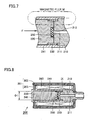
rubber packing 250 of movingcore 220 andnipple 212 of fixedcore 210 are separated from each other by means ofcoil spring 230, whereby air can flow out throughair passage 211. On the other hand, in a closed state, as shown in Fig. 7, the current is fed tocoil body 260, so that magnetic flux is generated by excitation ofcoil body 260 and movingcore 220 is attracted to and brought in contact withfixed core 210. In addition, nipple 212 is pressed byrubber packing 250 to closeair passage 211. - Here, reduction in size of
air valve 200 structured as above is considered. As shown in Fig. 8, it is possible to make smaller an outer diameter offrame 201, as well as to make smaller an outer diameter φ1 offixed core 210 and movingcore 220 for ensuring a volume ofcoil body 260. Taking into account the air flow rate, however, an inner diameter ofnipple 212 cannot be made smaller, or a diameter ofrubber packing 250 for closing nipple 212 cannot be changed either. Therefore, as shown in Fig. 9, an area of magnetic pole of movingcore 220 aroundrubber packing 250 is made smaller. In such a case, magnetic flux M is concentrated in a narrow area aroundrubber packing 250, which results in increase in magnetic reluctance, lower efficiency of a magnetic circuit, and lowering in the driving force. Consequently, attractive force of fixedcore 210 to be exerted on movingcore 220 may extremely be lowered, and leakage of air from nipple 212 is caused. Meanwhile; in order to obtain attractive force equivalent to that in the conventional example in the more compact structure shown in Fig. 8, the current should be increased, which results in increase in a current value. - In addition, as shown in Fig. 10, an end surface portion of moving
core 220 opposite to fixedcore 210 is covered bybobbin 241 made of resin composed of a non-magnetic material. As a gap L1 comparable to a thickness of the resin is present betweenframe cover 203 and movingcore 220 implementing the magnetic circuit, magnetic reluctance at gap L1 is increased, which may become a factor to lower efficiency of the magnetic circuit. - The present invention aims to solve the problems of lower driving force and lower efficiency of the magnetic circuit caused when the solenoid air valve is made smaller. From the foregoing, an object of the present invention is to provide a solenoid air valve structured such that an area of magnetic pole is sufficiently ensured even if a moving core is made thinner in order to ensure a volume of a coil body in reducing the solenoid air valve in size.
- A solenoid air valve according to the present invention includes: a fixed core fixed and adhered to inside of a frame made of a magnetic material; in the frame, a moving core accommodated in a bobbin made of a non-magnetic material in a manner movable in an axial direction; a gas outlet provided in a surface of the fixed core opposed to the moving core; a packing provided in a surface of the moving core opposed to the gas outlet; force-applying means for applying force to the moving core in a direction away from the fixed core; and a coil body for generating magnetic flux in order to form a magnetic circuit for generating force attracting the moving core toward the fixed core and bringing the same in contact. The moving core has a flange portion having a first diameter and a shaft portion having a second diameter smaller than the first diameter. The packing is provided in the flange portion, and the coil body is accommodated in a space between the bobbin surrounding the shaft portion and an inner circumferential surface of the frame.
- In the solenoid air valve according to the present invention, the moving core has the flange portion having a first diameter and the shaft portion having a second diameter smaller than the first diameter, and a packing is provided in the flange portion. Here, the flange portion having a larger diameter is opposed to the fixed core, so that reduction in the area of magnetic pole is avoided and driving force for closing the air outlet by means of the packing can sufficiently be ensured. In addition, the coil body is accommodated in a space between the bobbin surrounding the shaft portion and the inner circumferential surface of the frame, so that a smaller dimension of the outer diameter of the frame and a resultant smaller size of the solenoid air valve can be achieved, while ensuring the volume of the coil portion.
- The foregoing and other objects, features, aspects and advantages of the present invention will become more apparent from the following detailed description of the present invention when taken in conjunction with the accompanying drawings.
-
- Fig. 1 is a cross-sectional view of a structure of a solenoid air valve according to the present embodiment.
- Fig. 2 is a partially-enlarged cross-sectional view of an area encircled by II in Fig. 1.
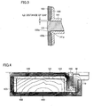
- Fig. 3 is a partially-enlarged cross-sectional view of an area encircled by III in Fig. 1.
- Fig. 4 shows magnetic flux density and a result of analysis of the magnetic flux, using the solenoid air valve according to the present embodiment as a model.
- Fig. 5 is a cross-sectional view of a structure of a conventional solenoid air valve.
- Fig. 6 is a partially-enlarged cross-sectional view of the structure of the conventional solenoid air valve (opened state).
- Fig. 7 is a partially-enlarged cross-sectional view of the structure of the conventional solenoid air valve (closed state).
- Fig. 8 is a cross-sectional view of a problem showing the conventional solenoid air valve.
- Fig. 9 is a partially-enlarged cross-sectional view showing a first problem of the conventional solenoid air valve.
- Fig. 10 is a partially-enlarged cross-sectional view showing a second problem of the conventional solenoid air valve.
- A structure of a solenoid air valve according to an embodiment of the present invention will be described hereinafter with reference to Figs. 1 to 3.
- Referring first to Fig. 1, the structure of a
solenoid air valve 100 in the present embodiment will be described.Solenoid air valve 100 includes aframe 101 made of a magnetic material.Frame 101 has a framemain body 102 and aframe cover 103 covering one end portion. For example, SUYB-1 (electromagnetic steel) or the like is used as a magnetic material for framemain body 102 andframe cover 103. Afixed core 110 is fixed and adhered to the inside of framemain body 102 on the other end side, such that a part of the fixed core projects outward. Anair passage 111 is provided in fixedcore 110, and a convex nipple (air outlet) 112 is provided at a position of fixedcore 110 opposed to a movingcore 120 which will be described later. In addition, framemain body 102houses moving core 120 accommodated in abobbin 140 made of a non-magnetic material in a manner movable in an axial direction. -
Movable core 120 includes aflange portion 122 arranged on a side of fixedcore 110, provided in a radially projecting manner and having a first diameter, and ashaft portion 121 having a second diameter smaller than the first diameter. Acoil spring 130 serving as force-applying means for applying force in a direction separatingflange portion 122 and fixedcore 110 is accommodated therebetween. A rubber packing 150 is embedded inflange portion 122 of movingcore 120 opposed tonipple 112. -
Bobbin 140 is provided along an outer circumferential surface of movingcore 120, and has ashaft portion area 141 provided alongshaft portion 121 of movingcore 120, aflange portion area 142 provided alongflange portion 122 fromshaft portion 121 offlange portion 122, anextension portion area 143 provided along the outer circumferential surface offlange portion 122, and aframe cover area 144 provided along an inner surface offrame cover 103 in an area opposite toflange portion area 142. Therefore,bobbin 140 has a dimension of an outer diameter offlange portion area 142 larger than that ofshaft portion area 141. - A
coil body 160 for generating magnetic flux is accommodated in a space between the outer circumferential surface ofshaft portion area 141 ofbobbin 140 and the inner circumferential surface of framemain body 102, in order to form a magnetic circuit for generating force attracting movingcore 120 toward fixedcore 110 and bringing the same in contact.Coil body 160 has a coil wire diameter of approximately Φ0.1mm, the number of tums of approximately 1000 and resistance of approximately 30Ω, and attains a coil current of approximately 80mA. - Referring to Figs. 1 and 3,
frame cover 103 has anopening 103a, through which an end portion ofshaft portion 121 of movingcore 120 projects outward. In an area whereshaft portion area 141 ofbobbin 140 intersects withframe cover area 144, aconvex portion 141a projecting towardframe cover 103 is provided. Inframe cover 103, aconcave portion 103b acceptingconvex portion 141 a is provided. - A current is fed to
coil body 160 insolenoid air valve 100 structured as above. As shown in Fig. 2, as a sufficient area of magnetic pole is ensured around rubber packing 150 inflange portion 122 of movingcore 120, magnetic reluctance is low and flow of magnetic flux M toward fixedcore 110 is smooth. In addition, asextension portion area 143 ofbobbin 140 made of a non-magnetic material extends along the outer circumferential surface offlange portion 122 of movingcore 120, it is ensured that magnetic flux M is guided toward fixedcore 110. - Here, it is known that magnetic reluctance of a gap (L) between fixed
electrode 110 andflange portion 122 of movingcore 120 can be expressed by equation (1) below.
(magnetic reluctance: R, distance of gap: L, magnetic pole area: S, relative permeability of air: µ0) - It can be seen from this equation (1) that, for ensuring driving force, an area of magnetic pole (S) should be made larger to lower magnetic reluctance R and enhance efficiency of the magnetic circuit. Paying attention to this equation, the present invention achieves a smaller size of the solenoid air valve in the following manner. Specifically, moving
core 120 is shaped like a flange consisting ofshaft portion 121 andflange portion 122, in order to ensure sufficient driving force for closingnipple 112 without reducing the area of magnetic pole opposed to a fixed electrode even when the diameter (φ1) of movingcore 120 is made smaller for ensuring a volume of the coil. - In addition,
coil body 160 is accommodated in the space betweenshaft portion area 141 ofbobbin 140 surroundingshaft portion 121 of movingcore 120 and the inner circumferential surface of framemain body 102, so that the dimension of the outer diameter offrame 101 is made smaller while ensuring the volume of a coil portion, and consequentlysolenoid air valve 100 can be reduced in size. - Moreover,
flange portion 122 is provided in movingcore 120 andflange portion area 142 alongflange portion 122 is provided inbobbin 140, so that a stop area is provided. The stop area defines a distance of travel of movingcore 120 in a direction away from fixedcore 110 by abutment of a surface offlange portion 122 opposite to fixedcore 110 andflange portion area 142 ofbobbin 140 when movingcore 120 moves alongbobbin 140 upon receiving force applied bycoil spring 130. - Accordingly, as it is not necessary to define a distance of travel at an end portion of the moving core, the end portion of
shaft portion 121 of movingcore 120 can project outward throughopening 103a offrame cover 103. Consequently, as shown in Fig. 3, a gap (distance: L2) between the surface offrame cover 103 facingshaft portion 121 and the side surface ofshaft portion 121 of movingcore 120 should only correspond to a distance of clearance in which movingcore 120 can slide. That is, the gap (distance: L2) can be minimized. As a result, magnetic reluctance betweenframe cover 103 and movingcore 120 due to this gap (distance) can be lowered (see equation 1), whereby efficiency of the magnetic circuit can be improved. - Preferably,
convex portion 141a andconcave portion 103b acceptingconvex portion 141a described above are provided betweenframe cover 103 andbobbin 140, as a positioning area for positioningframe cover 103 andbobbin 140. - Fig. 4 shows magnetic flux density and a result of analysis of the magnetic flux, using
solenoid air valve 100 according to the present embodiment as a model. The analysis result represents 1/4-scale CAE analysis model. The analysis result also shows that magnetic flux M throughflange portion 122 of movingcore 120 as well as in the gap between the surface offrame cover 103 facingshaft portion 121 and the side surface ofshaft portion 121 of movingcore 120 smoothly flows, without extremely been concentrated. - In the embodiment described above, the stop area has been formed by
flange portion 122 of movingcore 120 andflange portion area 142 ofbobbin 140. In order to define a distance of travel of movingcore 120 in the direction away from fixedcore 110, however, a mutual engagement area may separately be provided between the side surface of movingcore 120 andbobbin 140, for use as the stop area. - Although the present invention has been described and illustrated in detail, it is clearly understood that the same is by way of illustration and example only and is not to be taken by way of limitation, the spirit and scope of the present invention being limited only by the terms of the appended claims.
Claims (5)
- A solenoid air valve comprising:a fixed core (110) fixed and adhered to inside of a frame (101) made of a magnetic material;in said frame (101),a moving core (120) accommodated in a bobbin (140) made of a non-magnetic material in a manner movable in an axial direction;a gas outlet (111) provided in a surface of said fixed core (110) opposed to said moving core (120);a packing (150) provided in a surface of said moving core (120) opposed to said gas outlet (110);force-applying means (130) for applying force to said moving core (120) in a direction away from said fixed core (110); anda coil body (160) for generating magnetic flux in order to form a magnetic circuit for generating force attracting said moving core (120) toward said fixed core (110) and bringing the same in contact; whereinsaid moving core (120) has a flange portion (122) having a first diameter and a shaft portion (121) having a second diameter smaller than said first diameter, andsaid packing (150) is provided in said flange portion (122), and said coil body (160) is accommodated in a space between said bobbin (140) surrounding said shaft portion (121) and an inner circumferential surface of said frame (101).
- The solenoid air valve according to claim 1, wherein
an extension portion area (143) of said bobbin (140) is provided in a manner extending between the outer circumferential surface of said flange portion (122) and the inner circumferential surface of said frame (101). - The solenoid air valve according to claim 2, wherein
said bobbin (140) has a shaft portion area (141) provided along said shaft portion (121) of said moving core (120), a flange portion area (142) provided along said flange portion (122) from said shaft portion (121), said extension portion area (143) provided along the outer circumferential surface of said flange portion (122), and a frame cover area (144) provided along the inner circumferential surface of said frame (101) in an area opposite to said flange portion area (142). - The solenoid air valve according to claim 3, wherein
said frame (101) has a frame main body (102) and a frame cover (103) covering one end portion, and
said frame cover (103) has an opening (103 a), through which an end portion of said shaft portion (121) of said moving core (120) projects outward. - The solenoid air valve according to claim 4, wherein
in an area where said shaft portion area (141) of said bobbin (140) intersects with said frame cover area (144), a convex portion (141a) projecting toward said frame cover (103) is provided, and
in said frame cover (103), a concave portion (103b) accepting said convex portion (141a) is provided.
Applications Claiming Priority (1)
| Application Number | Priority Date | Filing Date | Title |
|---|---|---|---|
| JP2004206209A JP4576908B2 (en) | 2004-07-13 | 2004-07-13 | Solenoid air valve |
Publications (1)
| Publication Number | Publication Date |
|---|---|
| EP1617118A1 true EP1617118A1 (en) | 2006-01-18 |
Family
ID=35033589
Family Applications (1)
| Application Number | Title | Priority Date | Filing Date |
|---|---|---|---|
| EP05014835A Withdrawn EP1617118A1 (en) | 2004-07-13 | 2005-07-08 | Solenoid air valve |
Country Status (5)
| Country | Link |
|---|---|
| US (1) | US7049917B2 (en) |
| EP (1) | EP1617118A1 (en) |
| JP (1) | JP4576908B2 (en) |
| KR (1) | KR100727204B1 (en) |
| CN (1) | CN100394085C (en) |
Cited By (1)
| Publication number | Priority date | Publication date | Assignee | Title |
|---|---|---|---|---|
| CN103453148A (en) * | 2012-06-04 | 2013-12-18 | 厦门科际精密器材有限公司 | Electromagnetic pressure relief valve |
Families Citing this family (12)
| Publication number | Priority date | Publication date | Assignee | Title |
|---|---|---|---|---|
| US7104523B2 (en) * | 2004-06-12 | 2006-09-12 | Borgwarner Inc. | Valve having contamination counter-measures |
| US7564546B2 (en) * | 2004-06-30 | 2009-07-21 | Chemimage Corporation | Dynamic imaging of biological cells and other subjects |
| JP4219905B2 (en) * | 2005-02-25 | 2009-02-04 | 株式会社日立製作所 | Rotating gantry for radiation therapy equipment |
| JP4640211B2 (en) * | 2006-02-27 | 2011-03-02 | 株式会社デンソー | Electromagnetic drive device |
| US7800470B2 (en) | 2007-02-12 | 2010-09-21 | Engineering Matters, Inc. | Method and system for a linear actuator with stationary vertical magnets and coils |
| DE202008017033U1 (en) * | 2008-12-30 | 2010-05-12 | Eto Magnetic Gmbh | Electromagnetic actuator |
| KR101080871B1 (en) * | 2009-02-05 | 2011-11-07 | 르노삼성자동차 주식회사 | Solenoid valve apparatus |
| US8387945B2 (en) * | 2009-02-10 | 2013-03-05 | Engineering Matters, Inc. | Method and system for a magnetic actuator |
| CN102579027B (en) * | 2012-02-13 | 2013-12-11 | 刘忠发 | Button-type rapid air exhaust one-way air valve |
| JP6089517B2 (en) * | 2012-09-11 | 2017-03-08 | オムロンヘルスケア株式会社 | Flow rate control valve and blood pressure information measuring apparatus provided with the same |
| JP6248439B2 (en) * | 2013-07-10 | 2017-12-20 | オムロンヘルスケア株式会社 | Electromagnetic valve and electronic blood pressure monitor having the same |
| JP5541430B1 (en) * | 2013-08-19 | 2014-07-09 | ソニー株式会社 | Imaging unit, mounting device |
Citations (7)
| Publication number | Priority date | Publication date | Assignee | Title |
|---|---|---|---|---|
| FR2470990A1 (en) * | 1979-12-07 | 1981-06-12 | Lucas Industries Ltd | Solenoid operated fluid press. control valve - regulates pressure difference between inlet and outlet by varying flow |
| US4459991A (en) * | 1980-02-18 | 1984-07-17 | Asulab A.G. | Blood pressure measuring equipment |
| JPH09135817A (en) | 1995-11-16 | 1997-05-27 | Fukuda Denshi Co Ltd | Flow control valve and automatic blood pressure monitor equipped with the flow control valve |
| DE29707905U1 (en) * | 1997-05-02 | 1998-08-27 | Honeywell B.V., Amsterdam | Solenoid valve and its application for controlling the gas supply to a burner |
| JP2000097364A (en) | 1998-09-22 | 2000-04-04 | Terumo Corp | Constant speed exhaust valve |
| JP2003225213A (en) * | 2002-02-06 | 2003-08-12 | Aitekku:Kk | Blood pressure measuring device and electromagnetic exhaust valve |
| EP1617117A1 (en) * | 2004-07-12 | 2006-01-18 | Omron Healthcare Co., Ltd. | Solenoid air valve |
Family Cites Families (7)
| Publication number | Priority date | Publication date | Assignee | Title |
|---|---|---|---|---|
| GB2064720B (en) | 1979-12-07 | 1983-06-02 | Lucas Industries Ltd | Solenoid operated fluid pressure control valve |
| US5110087A (en) * | 1990-06-25 | 1992-05-05 | Borg-Warner Automotive Electronic & Mechanical Systems Corporation | Variable force solenoid hydraulic control valve |
| FR2717551B1 (en) * | 1994-03-17 | 1996-04-19 | Eaton Sa Monaco | Two-way solenoid valve for fluid. |
| US5992461A (en) * | 1998-08-18 | 1999-11-30 | Numatics, Incorporated | Solenoid valve housing |
| KR20010045839A (en) * | 1999-11-08 | 2001-06-05 | 최진섭 | Solenoid valve in refrigerant control device |
| JP4022850B2 (en) * | 2000-12-19 | 2007-12-19 | 株式会社デンソー | Solenoid valve and moving core assembly fixing method thereof |
| JP2002276839A (en) * | 2001-03-14 | 2002-09-25 | Staf Corp | Air valve |
-
2004
- 2004-07-13 JP JP2004206209A patent/JP4576908B2/en not_active Expired - Fee Related
-
2005
- 2005-07-08 US US11/176,688 patent/US7049917B2/en not_active Expired - Lifetime
- 2005-07-08 KR KR1020050061650A patent/KR100727204B1/en not_active Expired - Fee Related
- 2005-07-08 EP EP05014835A patent/EP1617118A1/en not_active Withdrawn
- 2005-07-11 CN CNB2005100835628A patent/CN100394085C/en not_active Expired - Fee Related
Patent Citations (7)
| Publication number | Priority date | Publication date | Assignee | Title |
|---|---|---|---|---|
| FR2470990A1 (en) * | 1979-12-07 | 1981-06-12 | Lucas Industries Ltd | Solenoid operated fluid press. control valve - regulates pressure difference between inlet and outlet by varying flow |
| US4459991A (en) * | 1980-02-18 | 1984-07-17 | Asulab A.G. | Blood pressure measuring equipment |
| JPH09135817A (en) | 1995-11-16 | 1997-05-27 | Fukuda Denshi Co Ltd | Flow control valve and automatic blood pressure monitor equipped with the flow control valve |
| DE29707905U1 (en) * | 1997-05-02 | 1998-08-27 | Honeywell B.V., Amsterdam | Solenoid valve and its application for controlling the gas supply to a burner |
| JP2000097364A (en) | 1998-09-22 | 2000-04-04 | Terumo Corp | Constant speed exhaust valve |
| JP2003225213A (en) * | 2002-02-06 | 2003-08-12 | Aitekku:Kk | Blood pressure measuring device and electromagnetic exhaust valve |
| EP1617117A1 (en) * | 2004-07-12 | 2006-01-18 | Omron Healthcare Co., Ltd. | Solenoid air valve |
Non-Patent Citations (3)
| Title |
|---|
| PATENT ABSTRACTS OF JAPAN vol. 1997, no. 09 30 September 1997 (1997-09-30) * |
| PATENT ABSTRACTS OF JAPAN vol. 2000, no. 07 29 September 2000 (2000-09-29) * |
| PATENT ABSTRACTS OF JAPAN vol. 2003, no. 12 5 December 2003 (2003-12-05) * |
Cited By (1)
| Publication number | Priority date | Publication date | Assignee | Title |
|---|---|---|---|---|
| CN103453148A (en) * | 2012-06-04 | 2013-12-18 | 厦门科际精密器材有限公司 | Electromagnetic pressure relief valve |
Also Published As
| Publication number | Publication date |
|---|---|
| US20060012454A1 (en) | 2006-01-19 |
| KR100727204B1 (en) | 2007-06-13 |
| US7049917B2 (en) | 2006-05-23 |
| JP2006029394A (en) | 2006-02-02 |
| CN1721744A (en) | 2006-01-18 |
| CN100394085C (en) | 2008-06-11 |
| KR20060049979A (en) | 2006-05-19 |
| JP4576908B2 (en) | 2010-11-10 |
Similar Documents
| Publication | Publication Date | Title |
|---|---|---|
| EP1617117B1 (en) | Solenoid air valve | |
| US7049917B2 (en) | Solenoid air valve | |
| US11166639B2 (en) | Flow control valve and blood pressure information measurement device having the same | |
| EP1847743B1 (en) | Electric-powered air release valve and blood pressure gauge | |
| US20110001072A1 (en) | Normally opened solenoid valve | |
| CN111712661B (en) | Electromagnetic valve, sphygmomanometer and equipment | |
| JP2019138403A5 (en) | ||
| JP6805558B2 (en) | Flow control valve, its manufacturing method, and blood pressure information measuring device | |
| JPH0333573A (en) | Electrically operated valve and assembling process of the same | |
| JP2006242232A (en) | Electric exhaust valve and blood pressure monitor | |
| JP2004185268A (en) | Flow regulator | |
| KR20140105182A (en) | Solenoid valve | |
| JP2004141568A (en) | Massage unit | |
| JPH1163283A (en) | Assembling method of poppet type solenoid proportional valve | |
| JP2017219061A (en) | Flow control valve and blood pressure information measuring device | |
| JP2006138658A (en) | Energization checker for solenoid valve coil | |
| JP2005155898A (en) | VALVE BODY, FLOW CONTROL DEVICE EQUIPPED WITH THIS VALVE BODY, AND BLOOD METER | |
| JP2020012522A (en) | solenoid valve |
Legal Events
| Date | Code | Title | Description |
|---|---|---|---|
| PUAI | Public reference made under article 153(3) epc to a published international application that has entered the european phase |
Free format text: ORIGINAL CODE: 0009012 |
|
| AK | Designated contracting states |
Kind code of ref document: A1 Designated state(s): AT BE BG CH CY CZ DE DK EE ES FI FR GB GR HU IE IS IT LI LT LU LV MC NL PL PT RO SE SI SK TR |
|
| AX | Request for extension of the european patent |
Extension state: AL BA HR MK YU |
|
| 17P | Request for examination filed |
Effective date: 20060714 |
|
| AKX | Designation fees paid |
Designated state(s): DE ES FR GB IT NL |
|
| 17Q | First examination report despatched |
Effective date: 20060906 |
|
| GRAP | Despatch of communication of intention to grant a patent |
Free format text: ORIGINAL CODE: EPIDOSNIGR1 |
|
| GRAS | Grant fee paid |
Free format text: ORIGINAL CODE: EPIDOSNIGR3 |
|
| GRAJ | Information related to disapproval of communication of intention to grant by the applicant or resumption of examination proceedings by the epo deleted |
Free format text: ORIGINAL CODE: EPIDOSDIGR1 |
|
| RIN1 | Information on inventor provided before grant (corrected) |
Inventor name: FUKUI, RYOICHI Inventor name: KARO, HIROMICHI Inventor name: KISHIMOTO, HIROSHI Inventor name: MATSUDA, HISATOMI Inventor name: MIYATANI, YASUTARO C/O OMRON CORPORATION Inventor name: SANO, YOSHIHIKO |
|
| STAA | Information on the status of an ep patent application or granted ep patent |
Free format text: STATUS: THE APPLICATION IS DEEMED TO BE WITHDRAWN |
|
| 18D | Application deemed to be withdrawn |
Effective date: 20080110 |