EP1617042A2 - Noise control - Google Patents
Noise control Download PDFInfo
- Publication number
- EP1617042A2 EP1617042A2 EP05253645A EP05253645A EP1617042A2 EP 1617042 A2 EP1617042 A2 EP 1617042A2 EP 05253645 A EP05253645 A EP 05253645A EP 05253645 A EP05253645 A EP 05253645A EP 1617042 A2 EP1617042 A2 EP 1617042A2
- Authority
- EP
- European Patent Office
- Prior art keywords
- noise
- blade
- blades
- attenuation
- duct
- Prior art date
- Legal status (The legal status is an assumption and is not a legal conclusion. Google has not performed a legal analysis and makes no representation as to the accuracy of the status listed.)
- Granted
Links
- 230000000694 effects Effects 0.000 claims abstract description 7
- 238000001228 spectrum Methods 0.000 claims description 39
- 230000035939 shock Effects 0.000 claims description 25
- 238000000034 method Methods 0.000 claims description 23
- 230000004044 response Effects 0.000 claims description 5
- 230000001419 dependent effect Effects 0.000 claims description 3
- 238000004519 manufacturing process Methods 0.000 abstract description 5
- 238000011282 treatment Methods 0.000 abstract description 5
- 230000002238 attenuated effect Effects 0.000 abstract description 3
- 230000009467 reduction Effects 0.000 abstract description 3
- 230000007613 environmental effect Effects 0.000 abstract description 2
- 230000008707 rearrangement Effects 0.000 abstract 1
- 238000004590 computer program Methods 0.000 description 5
- 238000013461 design Methods 0.000 description 5
- 230000009021 linear effect Effects 0.000 description 3
- 238000013459 approach Methods 0.000 description 2
- 230000009286 beneficial effect Effects 0.000 description 2
- 238000011144 upstream manufacturing Methods 0.000 description 2
- 230000008859 change Effects 0.000 description 1
- 230000001010 compromised effect Effects 0.000 description 1
- 230000002596 correlated effect Effects 0.000 description 1
- 238000010586 diagram Methods 0.000 description 1
- 238000002474 experimental method Methods 0.000 description 1
- 239000012530 fluid Substances 0.000 description 1
- 238000012986 modification Methods 0.000 description 1
- 230000004048 modification Effects 0.000 description 1
- 230000009022 nonlinear effect Effects 0.000 description 1
- 230000001902 propagating effect Effects 0.000 description 1
- 230000035945 sensitivity Effects 0.000 description 1
- 230000003595 spectral effect Effects 0.000 description 1
- 238000012360 testing method Methods 0.000 description 1
Images


Classifications
-
- F—MECHANICAL ENGINEERING; LIGHTING; HEATING; WEAPONS; BLASTING
- F02—COMBUSTION ENGINES; HOT-GAS OR COMBUSTION-PRODUCT ENGINE PLANTS
- F02C—GAS-TURBINE PLANTS; AIR INTAKES FOR JET-PROPULSION PLANTS; CONTROLLING FUEL SUPPLY IN AIR-BREATHING JET-PROPULSION PLANTS
- F02C7/00—Features, components parts, details or accessories, not provided for in, or of interest apart form groups F02C1/00 - F02C6/00; Air intakes for jet-propulsion plants
- F02C7/04—Air intakes for gas-turbine plants or jet-propulsion plants
- F02C7/045—Air intakes for gas-turbine plants or jet-propulsion plants having provisions for noise suppression
-
- F—MECHANICAL ENGINEERING; LIGHTING; HEATING; WEAPONS; BLASTING
- F05—INDEXING SCHEMES RELATING TO ENGINES OR PUMPS IN VARIOUS SUBCLASSES OF CLASSES F01-F04
- F05D—INDEXING SCHEME FOR ASPECTS RELATING TO NON-POSITIVE-DISPLACEMENT MACHINES OR ENGINES, GAS-TURBINES OR JET-PROPULSION PLANTS
- F05D2260/00—Function
- F05D2260/96—Preventing, counteracting or reducing vibration or noise
-
- Y—GENERAL TAGGING OF NEW TECHNOLOGICAL DEVELOPMENTS; GENERAL TAGGING OF CROSS-SECTIONAL TECHNOLOGIES SPANNING OVER SEVERAL SECTIONS OF THE IPC; TECHNICAL SUBJECTS COVERED BY FORMER USPC CROSS-REFERENCE ART COLLECTIONS [XRACs] AND DIGESTS
- Y02—TECHNOLOGIES OR APPLICATIONS FOR MITIGATION OR ADAPTATION AGAINST CLIMATE CHANGE
- Y02T—CLIMATE CHANGE MITIGATION TECHNOLOGIES RELATED TO TRANSPORTATION
- Y02T50/00—Aeronautics or air transport
- Y02T50/60—Efficient propulsion technologies, e.g. for aircraft
Definitions
- the present invention relates to noise control and more particularly to noise control with regard to rotating machinery such as a gas turbine engine.
- the shocks in a) are all of equal amplitude and spacing around the fan disk and no buzz-saw noise results whilst the shocks in b) are not equal and buzz-saw noise is generated.
- the diagram refers to an aerodynamic condition at part speed where the shocks become "detached”. At this condition the shock non-uniformities for case b) are in fact known to be proportional to the difference in stagger angles. So that in b) S n+1 ⁇ n+1 - ⁇ n (equation 1) where S n+1 is the shock strength on the n+1 th blade, ⁇ n+1 is the stagger angle of the n+1 th blade and ⁇ n is the stagger angle on the n th blade. At speeds closer to design the shocks may become "swallowed". In this case the shocks will depend upon the stagger angle.
- the shocks will also have a dependence upon other blade-to-blade geometric differences such as thickness, camber, lean and leading edge blade angle.
- the harmonic frequencies of the buzz-saw noise are those of the harmonics of the disc rotational frequency of the fan called here engine orders.
- the invention is effective for either part speed conditions where the shocks are "detached” or at design conditions where the shocks are "swallowed”.
- the principal problem relates to the non-uniformity of the rotating assembly geometry creating disparities in the regularity of shocks at the rotational speeds defined. These disparities with respect to the adjacent casing or duct wall cause the associated buzz-saw noise.
- the use of acoustic wall treatments to attenuate noise levels is inhibited by the variable nature of the frequencies of the noise as well as the nature of the acoustic wall treatment, which disproportionately attenuates noise at different frequencies.
- a method of noise control for a plurality of blades mounted on a disc or hub to rotate within a housing whereby when rotating those blades cause noise comprising;
- the noise frequency spectrum is shifted by matching harmonic frequency distribution determinations.
- noise frequency spectrum is determined by experiment or theory or by empirical means.
- the noise frequency spectrum at the rotor can be determined using an equation S n+1 ⁇ ⁇ n+1 - ⁇ n where S n+1 is the shock strength on the n+1 th blade and ⁇ n+1 is the stagger angle on the n+1 th blade and ⁇ n is the stagger angle on the n th blade.
- the plurality of the blades may be arranged to also provide unbalance, blade stress or flutter limitation and/or to reduce stagger differences between adjacent blades and/or to control the variation in spacing of rotational shocks affecting higher frequency noise and/or to minimise blade to blade geometric differences.
- a noise control arrangement for a plurality of blades mounted on a disc or hub to rotate within a duct whereby when rotating those blades cause noise, the duct including noise attenuation means with varying attenuation frequency response dependent upon noise frequency, and the blades mounted in specific order upon the disc or hub to enhance, upon rotation, the proportion of noise at the harmonic frequencies of higher attenuation by the noise attenuation means.
- the plurality of the blades are also arranged to provide rotor unbalance, blade stress or flutter limitation and/or to reduce blade stagger angle differences between adjacent blades and/or to control spacing of rotational shocks and/or to minimise blade to blade geometric differences.
- the blade differences which determine the buzz-saw noise frequency spectrum are often found to be almost constant with fan speed despite the obvious blade untwist which occurs to the blade stagger angle when a rotating assembly is run.
- the buzz-saw noise frequency spectrum will therefore in most cases be dependent only upon the rotor speed and the blade to blade differences. If however the spectrum is expressed in terms of engine order instead of frequency where engine order is the frequency of the engine LP shaft rotation, then this engine ordered spectrum is to a large degree constant with rotor speed. Then by reordering the blades, the engine ordered spectrum can be optimised to the noise attenuation of the duct liner. Often this means that the blade set is only perfectly optimised at one critical speed but the benefits are spread over a wider range of speeds.
- Other blade parameters which may control the shock and hence the buzz-saw noise spectrum are blade camber, blade lean and interblade spacing.
- blades may also be arranged at the same time to provide a minimal moment weight unbalance and/or minimal unevenness of tip rub against the fan case and/or minimal blade flutter characteristics. Limits for these parameters can also be incorporated into the method.
- Fig. 2a if a fan assembly consists of B unequal stagger angles, the buzz-saw noise spectrum is predicted using the stagger angles of the blades in order around the disc according to equation 2 above for each engine order (r) of blades.
- Fig. 2a shows a typical predicted buzz-saw noise spectrum obtained in this way.
- the spectral character is symmetric about engine orders 0.5B, 1.5, 2.5B and 3.5B (in fact this is true also for 4.5B, 5.5B, .etc.).
- the noise is that of the rotor-alone blade passing noise which would be produced even if there were no blade to blade differences.
- the noise is produced by the blade to blade differences (in this case stagger angle) and is in fact the buzz-saw noise of the fan.
- This noise is characterized by the spectrum amplitude shape which in fact repeats between zero engine order and blade passing engine order and between every blade passing frequency harmonic (i.e. engine order B or multiple of B). Any change to the spectrum shape due to a different blade order will therefore be reflected between every blade passing harmonic.
- a particular design of acoustic liner may have an attenuation spectrum similar to that depicted in Fig. 2b (though in principle the liner could be designed to any frequency attenuation shape).
- the attenuation frequency spectrum may be translated into an engine order spectrum from knowledge of the engine LP shaft rotation rate as in Fig. 2c.
- This attenuation spectrum of the liner becomes altered when incorporated into a duct due to cut-off effects. This occurs at low engine orders and can be calculated in a standard manner from knowledge of the fan blade number, blade tip Mach number, duct radius and Mach numbers of the flow within the duct.
- Fig. 2d shows a typical attenuation engine order spectrum of the duct/acoustic liner combination.
- An algorithm may be created in the form of a computer program to calculate the predicted buzz-saw noise spectrum after attenuation in the manner described above.
- a new buzz-saw noise spectrum can quickly be calculated using the program if one blade pair is swapped.
- the program can also calculate the total noise difference between any two blade swaps. This total noise difference can be used to decide whether to keep the blade swap or not, i.e. if the total noise is reduced the blade swap is kept.
- the computer program can do very many blade swaps in this way and fairly quickly to find a blade order which has optimum noise. In principle what the computer program is doing is transferring the noise from engine blade orders where there is not much attenuation by the liner or duct, etc. to engine blade orders where there is more attenuation.
- the program does this by swapping blades around the fan disc until it finds the optimum blade order for optimum total noise.
- no computer is yet fast enough to test all these blade orders however the computer can fairly quickly obtain an optimum total noise after a few thousand swaps have been tried.
- the method might be changed to also include limiting fan flutter or engine orders known to cause vibration in the fan and adjoining structures.
- total noise between any two blade swaps was chosen as a measure of the success of the noise reduction.
- the total noise is merely an addition of square pressure amplitudes of the noise at each engine order.
- the total noise and the noise at each engine order is usually expressed as a SPL level in dB where the SPL is defined as 10log (square pressure amplitude/reference value). It would equally be possible to use some other measure of noise as a way to optimize the blade order.
- PNL or dBA These units are also expressed like the total noise in dB but are frequency weighted to reflect the response of human ear. Frequency weightings could also be added to the method for atmospheric attenuation or aircraft cabin wall attenuation.
- the non-linear noise attenuation for a given engine order noise spectrum at the rotor can be calculated for an acoustically lined duct for each engine order of the spectrum.
- the method would then proceed in exactly the same way as before except that the predicted duct liner attenuation would include these non linear effects and the predicted buzz-saw noise would more accurately reflect the actual buzz-saw noise at the exit of the duct.
- This addition to the method might be very beneficial since the non linear attenuation will increase the variation from shock on one blade to the shock on the next blade.
- the shocks will not only vary in amplitude from blade to blade but also in the circumferential position of the shocks. Since these variations in position can affect the higher frequencies of the buzz-saw spectrum, optimizing the spectrum using this modification could be also beneficial to the higher frequencies.
- a prediction of noise using equation 2 will have some errors when compared to measured data. These errors can be included in the prediction by assuming they are uncorrelated with, for example, stagger angle. So for example, the prediction of noise using stagger angle differences alone becomes, F r ( ⁇ n + 1 - ⁇ n ) + F r (errors) where error can be determined by the errors required to match the prediction to the measured data.
- the method can also be combined with procedures for selecting blades from a blade repository to minimize certain blade to blade differences in a fan blade set.
- the method in the form of a computer program could be used by the aeroengine owners to reorder the blades after blade replacements due to damage or some other reasons. Thus ensuring the fan remains optimized throughout it's life.
Landscapes
- Engineering & Computer Science (AREA)
- Chemical & Material Sciences (AREA)
- Combustion & Propulsion (AREA)
- Mechanical Engineering (AREA)
- General Engineering & Computer Science (AREA)
- Structures Of Non-Positive Displacement Pumps (AREA)
- Measurement Of Mechanical Vibrations Or Ultrasonic Waves (AREA)
- Turbine Rotor Nozzle Sealing (AREA)
Abstract
Description
- The present invention relates to noise control and more particularly to noise control with regard to rotating machinery such as a gas turbine engine.
- Control of noise is important as sensitivity to the perceived environment increases. Thus, such rotating machinery as gas turbine engines and in particular such engines used for aircraft operations are constantly reviewed in terms of noise targets. Clearly, these noise targets are increasingly stringent with an ongoing objective to reduce environmental and where appropriate aircraft cabin noise. Nevertheless, rotating machinery by its nature will create noise and in particular so called buzz saw noise generated by the rotating fan assembly.
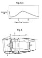
- Buzz-saw noise occurs when the fan assembly operates with the rotor blade tips - or a lower span of the rotor blades - at sonic or supersonic Mach numbers, i.e. when Mr > 1. Where Mr is the resultant rotor relative tip Mach number associated with the inlet fluid flow Mach number in the stationary frame of reference, Ma and the effective blade tip circumferential Mach number Mt. i.e. Mr = √(Mt 2 + Ma 2). Where Mach no. = velocity / speed of sound. The shock waves, generated by the rotor assembly will sweep over the outer wall of the annulus and propagate upstream and out of the engine intake. When the outer annulus wall is treated with an acoustic layer the propagating noise will be attenuated and a lower sound pressure level will be experienced at an upstream plane relative to an engine with the same hardware but with no acoustic treatment.
- The buzz-saw noise arises from the production of non-uniform shock waves resulting from the blade-to-blade geometric differences associated with the manufacturing tolerances of the rotor blades. If all blades were manufactured identically then no buzz-saw noise would occur and rotor only noise would occur at blade passing frequencies and its harmonics. This noise would then be observed by a stationary observer relative to the rotor assembly. However such a reduction in tolerances will significantly increase the manufacturing cost of the rotor blades. Fig. 1 below shows an example, considering blade stagger angle alone, of the effect of a) all blades being identical b) the effect of one blade stagger angle being larger than the others. The shocks in a) are all of equal amplitude and spacing around the fan disk and no buzz-saw noise results whilst the shocks in b) are not equal and buzz-saw noise is generated. The diagram refers to an aerodynamic condition at part speed where the shocks become "detached". At this condition the shock non-uniformities for case b) are in fact known to be proportional to the difference in stagger angles. So that in b) Sn+1 ∝Θn+1 - Θn (equation 1) where Sn+1 is the shock strength on the n+1 th blade, Θn+1 is the stagger angle of the n+1 th blade and Θn is the stagger angle on the n th blade. At speeds closer to design the shocks may become "swallowed". In this case the shocks will depend upon the stagger angle.
- At either condition the shocks will also have a dependence upon other blade-to-blade geometric differences such as thickness, camber, lean and leading edge blade angle. The harmonic frequencies of the buzz-saw noise are those of the harmonics of the disc rotational frequency of the fan called here engine orders. The invention is effective for either part speed conditions where the shocks are "detached" or at design conditions where the shocks are "swallowed".
- From the above it will be appreciated that the principal problem relates to the non-uniformity of the rotating assembly geometry creating disparities in the regularity of shocks at the rotational speeds defined. These disparities with respect to the adjacent casing or duct wall cause the associated buzz-saw noise. The use of acoustic wall treatments to attenuate noise levels is inhibited by the variable nature of the frequencies of the noise as well as the nature of the acoustic wall treatment, which disproportionately attenuates noise at different frequencies.
- Acoustic duct liner design for frequency and attenuation is usually compromised for different specific noise sources such as broadband noise or specific aircraft conditions such as approach, take-off or cruise. Therefore the attenuation-frequency spectrum characteristic of the duct liner are usually far from ideal for the buzz-saw noise source considered here. In such circumstances, previously greater effort has been placed upon improving blade manufacturing tolerances and assembly accuracy. Nevertheless, there are commercial as well as practical limits to such approaches, i.e. more accurately manufactured and assembled blades will greatly increase costs.
- In accordance with the present invention there is provided a method of noise control for a plurality of blades mounted on a disc or hub to rotate within a housing whereby when rotating those blades cause noise, the method comprising;
- a) Determination of a noise attenuation frequency spectrum within the housing and any attenuation means associated with that housing;
- b) Determination of a noise frequency spectrum at the rotor face for the plurality of blades when specifically rotated; and,
- c) Rearranging specific blade positions upon the disc or hub to optimise the noise frequency spectrum for more consistency with the attenuation of the duct and any noise attenuation means for greater noise control.
- Typically, the noise frequency spectrum is shifted by matching harmonic frequency distribution determinations.
- Generally, determination of the noise frequency spectrum is performed by experiment or theory or by empirical means.
- Additionally, for b uneven blades and when the acoustic liner in the duct is most effective in the engine order range n to m then it is necessary to arrange the blades around the disc or hub to ensure the 1 to (n-1) Fourier coefficients and m to (b-1) Fourier coefficients of either one or more combinations of stagger, thickness, camber, lean, and leading edge blade angle of the blade set are reduced.
- Additionally, wherein the noise frequency spectrum at the rotor can be determined using an equation Sn+1 ∝ θn+1 - θn where Sn+1 is the shock strength on the n+1 th blade and θn+1 is the stagger angle on the n+1 th blade and θn is the stagger angle on the n th blade.
- In addition to the arrangement of blades to control noise, the plurality of the blades may be arranged to also provide unbalance, blade stress or flutter limitation and/or to reduce stagger differences between adjacent blades and/or to control the variation in spacing of rotational shocks affecting higher frequency noise and/or to minimise blade to blade geometric differences.
- There may be a blade repository comprising a plurality of blades of known replacement response and one of those replacement blades may be used to replace a blade in the plurality of blades.
- Also, in accordance with the present invention there is a noise control arrangement for a plurality of blades mounted on a disc or hub to rotate within a duct whereby when rotating those blades cause noise, the duct including noise attenuation means with varying attenuation frequency response dependent upon noise frequency, and the blades mounted in specific order upon the disc or hub to enhance, upon rotation, the proportion of noise at the harmonic frequencies of higher attenuation by the noise attenuation means.
- Advantageously, the plurality of the blades are also arranged to provide rotor unbalance, blade stress or flutter limitation and/or to reduce blade stagger angle differences between adjacent blades and/or to control spacing of rotational shocks and/or to minimise blade to blade geometric differences.
- The blade differences which determine the buzz-saw noise frequency spectrum are often found to be almost constant with fan speed despite the obvious blade untwist which occurs to the blade stagger angle when a rotating assembly is run. The buzz-saw noise frequency spectrum will therefore in most cases be dependent only upon the rotor speed and the blade to blade differences. If however the spectrum is expressed in terms of engine order instead of frequency where engine order is the frequency of the engine LP shaft rotation, then this engine ordered spectrum is to a large degree constant with rotor speed. Then by reordering the blades, the engine ordered spectrum can be optimised to the noise attenuation of the duct liner. Often this means that the blade set is only perfectly optimised at one critical speed but the benefits are spread over a wider range of speeds.
- If a fan blade assembly consists of B unequal blades, then a buzz-saw noise prediction can be obtained using the following equation, Fr (θn+1-θn) where Fr is the rth Fourier coefficient for a set of blade stagger angles n=1 to B (equation 2). In this way the engine ordered amplitude can be calculated for each engine order r of the spectrum. It is not necessary to predict the absolute value of the buzz-saw noise but only to give the correct relative noise value given by any stagger angle, blade order or engine order.
-
Equation 2 can be modified for any other rotor blade parameter which buzz-saw noise may depend upon. So for example, if differences in blade thickness is an important factor in the buzz-saw noise then the buzz-saw noise prediction could include a term such as Fr (tn) where Fr is the rth Fourier coefficient for a set of blade thicknesses of blades n=1 to B. Also if the blade shock is swallowed which it may be at some operating conditions the buzz-saw noise may depend upon stagger angle so that the buzz-saw noise prediction may include a term Fr (θn) where Fr is the rth Fourier coefficient for a set of blade stagger angles n=1 to B. Other blade parameters which may control the shock and hence the buzz-saw noise spectrum are blade camber, blade lean and interblade spacing. - It has however been found that stagger angle difference is the most important cause of buzz-saw noise for the type of aeroengine fans most commonly encountered and at the aircraft conditions most critical to buzz-saw noise. In principle however the present method could be used for predicting the noise according to which blade parameter terms are most important for the rotating assembly design and/or aircraft condition. In accordance with the method the blades will then be reordered to optimise noise attenuation with the duct liner using the modified buzz-saw noise prediction.
- Additionally the blades may also be arranged at the same time to provide a minimal moment weight unbalance and/or minimal unevenness of tip rub against the fan case and/or minimal blade flutter characteristics. Limits for these parameters can also be incorporated into the method.
- Embodiments of the present invention will now be described by way of example only and with reference to Fig. 2. Referring to Fig. 2a, if a fan assembly consists of B unequal stagger angles, the buzz-saw noise spectrum is predicted using the stagger angles of the blades in order around the disc according to
equation 2 above for each engine order (r) of blades. Fig. 2a shows a typical predicted buzz-saw noise spectrum obtained in this way. We note that the spectral character is symmetric about engine orders 0.5B, 1.5, 2.5B and 3.5B (in fact this is true also for 4.5B, 5.5B, .....etc.). At each engine order B or multiple of B, the noise is that of the rotor-alone blade passing noise which would be produced even if there were no blade to blade differences. At other engine orders the noise is produced by the blade to blade differences (in this case stagger angle) and is in fact the buzz-saw noise of the fan. - This noise is characterized by the spectrum amplitude shape which in fact repeats between zero engine order and blade passing engine order and between every blade passing frequency harmonic (i.e. engine order B or multiple of B). Any change to the spectrum shape due to a different blade order will therefore be reflected between every blade passing harmonic.
- A particular design of acoustic liner may have an attenuation spectrum similar to that depicted in Fig. 2b (though in principle the liner could be designed to any frequency attenuation shape). At any particular rotational speed which may be deemed critical to noise, the attenuation frequency spectrum may be translated into an engine order spectrum from knowledge of the engine LP shaft rotation rate as in Fig. 2c. This attenuation spectrum of the liner becomes altered when incorporated into a duct due to cut-off effects. This occurs at low engine orders and can be calculated in a standard manner from knowledge of the fan blade number, blade tip Mach number, duct radius and Mach numbers of the flow within the duct. Fig. 2d shows a typical attenuation engine order spectrum of the duct/acoustic liner combination.
- At each engine order the buzz-saw noise after propagation through the liner can now be obtained by simply subtracting the attenuation spectrum of the duct/liner in Fig. 2d from the predicted buzz-saw spectrum in Fig. 2a. Thus the spectrum after attenuation is obtained in Fig. 2e.
- An algorithm may be created in the form of a computer program to calculate the predicted buzz-saw noise spectrum after attenuation in the manner described above. A new buzz-saw noise spectrum can quickly be calculated using the program if one blade pair is swapped. The program can also calculate the total noise difference between any two blade swaps. This total noise difference can be used to decide whether to keep the blade swap or not, i.e. if the total noise is reduced the blade swap is kept. The computer program can do very many blade swaps in this way and fairly quickly to find a blade order which has optimum noise. In principle what the computer program is doing is transferring the noise from engine blade orders where there is not much attenuation by the liner or duct, etc. to engine blade orders where there is more attenuation. The program does this by swapping blades around the fan disc until it finds the optimum blade order for optimum total noise. Note that the total number of possible blade arrangements around the fan disc is (B-1)! for an aeroengine fan with the number of blades being B=25, this would mean 24! or 6.204x10²³ ways of ordering the fan blades. In practice no computer is yet fast enough to test all these blade orders however the computer can fairly quickly obtain an optimum total noise after a few thousand swaps have been tried. Also there are other constraints to the blade order that the computer program has to make to reduce to some predefined limit the moment weight unbalance of the fan and to limit the degree of blade tip rub against the fan case. The method might be changed to also include limiting fan flutter or engine orders known to cause vibration in the fan and adjoining structures.
- In this example, total noise between any two blade swaps was chosen as a measure of the success of the noise reduction. The total noise is merely an addition of square pressure amplitudes of the noise at each engine order. The total noise and the noise at each engine order is usually expressed as a SPL level in dB where the SPL is defined as 10log (square pressure amplitude/reference value). It would equally be possible to use some other measure of noise as a way to optimize the blade order. For example, PNL or dBA. These units are also expressed like the total noise in dB but are frequency weighted to reflect the response of human ear. Frequency weightings could also be added to the method for atmospheric attenuation or aircraft cabin wall attenuation.
- One important factor which can be added to the method is the influence on the noise of non-linear noise attenuation which occurs along the duct length. The non-linear noise attenuation for a given engine order noise spectrum at the rotor can be calculated for an acoustically lined duct for each engine order of the spectrum. The method would then proceed in exactly the same way as before except that the predicted duct liner attenuation would include these non linear effects and the predicted buzz-saw noise would more accurately reflect the actual buzz-saw noise at the exit of the duct. This addition to the method might be very beneficial since the non linear attenuation will increase the variation from shock on one blade to the shock on the next blade. Therefore at the end of the duct, the shocks will not only vary in amplitude from blade to blade but also in the circumferential position of the shocks. Since these variations in position can affect the higher frequencies of the buzz-saw spectrum, optimizing the spectrum using this modification could be also beneficial to the higher frequencies.
- Another important factor which can be added to the method is the influence of non-correlated noise. For example, a prediction of
noise using equation 2 will have some errors when compared to measured data. These errors can be included in the prediction by assuming they are uncorrelated with, for example, stagger angle. So for example, the prediction of noise using stagger angle differences alone becomes, Fr (θn + 1-θn) + Fr (errors) where error can be determined by the errors required to match the prediction to the measured data. - The method can also be combined with procedures for selecting blades from a blade repository to minimize certain blade to blade differences in a fan blade set.
- Once the aeroengine is in service, the method in the form of a computer program could be used by the aeroengine owners to reorder the blades after blade replacements due to damage or some other reasons. Thus ensuring the fan remains optimized throughout it's life.
Claims (10)
- A method of noise control for a plurality of blades mounted on a disc or hub to rotate within a housing whereby when rotating those blades cause noise, the method comprising;a) Determination of a noise attenuation frequency spectrum within the housing and any attenuation means associated with that housing;b) Determination of a noise frequency spectrum at the rotor face for the plurality of blades when specifically rotated; and,c) Rearranging specific blade positions upon the disc or hub to optimise the noise frequency spectrum for more consistency with the attenuation of the duct and any noise attenuation means for greater noise control.
- A method as claimed in claim 1 wherein the noise frequency spectrum is shifted by matching harmonic frequency distribution determinations.
- A method as claimed in claim 1 or claim 2 wherein determination of the noise frequency spectrum is performed by experimental, theoretical or by empirical means.
- A method as claimed in any preceding claim wherein the noise attenuation spectrum and related duct effects are determined by experimental, theoretical or empirical means
- A method as claimed in any preceding claim wherein for b uneven blades and when the acoustic liner in the duct is most effective in the engine order range n to m then it is necessary to arrange the blades around the disc or hub to ensure the 1 to (n-1) Fourier coefficients and m to (b-1) Fourier coefficients of either one or more combinations of stagger, thickness, camber, lean, and leading edge blade angle of the blade set are reduced.
- A method as claimed in any preceding claim wherein the noise frequency spectrum is determined using an equation such as Sn+1 ∝ θn+1 - θn where Sn+1 is the shock strength on the n+1 th blade and θn+1 is the stagger angle on the n+1 th blade and θn is the stagger angle on the n th blade.
- A method as claimed in any preceding claim wherein the plurality of the blades are also arranged to provide unbalance, blade stress or flutter limitation and/or to reduce stagger differences between adjacent blades and/or to control spacing of rotational shock affecting higher frequency noise and/or to minimise blade to blade geometric differences.
- A method as claimed in any preceding claim wherein there is a blade repository comprising a plurality of blades of known replacement response and one of those replacement blades used to replace a blade in the plurality of blades.
- A noise control arrangement for a plurality of blades mounted on a disc or hub to rotate within a duct whereby when rotating those blades cause noise, the duct including noise attenuation means with varying attenuation response dependent upon noise frequency, and the blades mounted in specific order upon the disc or hub to enhance, upon rotation, the proportion of noise at the harmonic frequencies of higher attenuation by the noise attenuation means.
- An arrangement as claimed in claim 9 wherein the plurality of the blades are also arranged to provide rotor unbalance and/or blade stress and/or flutter limitation and/or to reduce stagger between adjacent blades and/or to control spacing of rotational shocks and/or to minimise blade to blade geometric differences.
Applications Claiming Priority (1)
| Application Number | Priority Date | Filing Date | Title |
|---|---|---|---|
| GBGB0415844.0A GB0415844D0 (en) | 2004-07-15 | 2004-07-15 | Noise control |
Publications (3)
| Publication Number | Publication Date |
|---|---|
| EP1617042A2 true EP1617042A2 (en) | 2006-01-18 |
| EP1617042A3 EP1617042A3 (en) | 2011-12-14 |
| EP1617042B1 EP1617042B1 (en) | 2013-10-23 |
Family
ID=32893610
Family Applications (1)
| Application Number | Title | Priority Date | Filing Date |
|---|---|---|---|
| EP05253645.5A Ceased EP1617042B1 (en) | 2004-07-15 | 2005-06-14 | A method of noise control for a plurality of blades mounted on a rotor disc |
Country Status (3)
| Country | Link |
|---|---|
| US (1) | US7648330B2 (en) |
| EP (1) | EP1617042B1 (en) |
| GB (1) | GB0415844D0 (en) |
Cited By (1)
| Publication number | Priority date | Publication date | Assignee | Title |
|---|---|---|---|---|
| US11047244B2 (en) | 2018-11-12 | 2021-06-29 | Rolls-Royce Plc | Rotor blade arrangement |
Families Citing this family (19)
| Publication number | Priority date | Publication date | Assignee | Title |
|---|---|---|---|---|
| US7861823B2 (en) * | 2005-11-04 | 2011-01-04 | United Technologies Corporation | Duct for reducing shock related noise |
| US8602156B2 (en) * | 2006-05-19 | 2013-12-10 | United Technologies Corporation | Multi-splice acoustic liner |
| GB0620769D0 (en) * | 2006-10-19 | 2006-11-29 | Rolls Royce Plc | A fan blade |
| US8167540B2 (en) * | 2008-01-30 | 2012-05-01 | Hamilton Sundstrand Corporation | System for reducing compressor noise |
| US8172510B2 (en) * | 2009-05-04 | 2012-05-08 | Hamilton Sundstrand Corporation | Radial compressor of asymmetric cyclic sector with coupled blades tuned at anti-nodes |
| US8172511B2 (en) * | 2009-05-04 | 2012-05-08 | Hamilton Sunstrand Corporation | Radial compressor with blades decoupled and tuned at anti-nodes |
| WO2014143280A1 (en) * | 2013-03-15 | 2014-09-18 | United Technologies Corporation | Gas turbine blade array with reduced acoustic output |
| FR3029576B1 (en) * | 2014-12-04 | 2016-12-30 | Snecma | METHOD FOR REDUCING THE NOISE LEVEL OF A TURBOMACHINE BLOWER |
| FR3037111B1 (en) | 2015-06-08 | 2017-05-19 | Snecma | PROCESS FOR MANUFACTURING TURBOMACHINE BLOWER WITH REDUCED NOISE LEVEL AT MULTIPLE ROTATION FREQUENCIES OF TURBOMACHINE |
| US10215194B2 (en) | 2015-12-21 | 2019-02-26 | Pratt & Whitney Canada Corp. | Mistuned fan |
| US10344711B2 (en) * | 2016-01-11 | 2019-07-09 | Rolls-Royce Corporation | System and method of alleviating blade flutter |
| CA2958459C (en) | 2016-02-19 | 2025-07-08 | Pratt & Whitney Canada Corp. | Compressor rotor for supersonic flutter and/or resonant stress mitigation |
| US10458436B2 (en) | 2017-03-22 | 2019-10-29 | Pratt & Whitney Canada Corp. | Fan rotor with flow induced resonance control |
| US10480535B2 (en) | 2017-03-22 | 2019-11-19 | Pratt & Whitney Canada Corp. | Fan rotor with flow induced resonance control |
| US10823203B2 (en) | 2017-03-22 | 2020-11-03 | Pratt & Whitney Canada Corp. | Fan rotor with flow induced resonance control |
| US10465539B2 (en) * | 2017-08-04 | 2019-11-05 | Pratt & Whitney Canada Corp. | Rotor casing |
| GB201808646D0 (en) * | 2018-05-25 | 2018-07-11 | Rolls Royce Plc | Rotor Blade Arrangement |
| GB201808651D0 (en) | 2018-05-25 | 2018-07-11 | Rolls Royce Plc | Rotor blade arrangement |
| GB201808650D0 (en) * | 2018-05-25 | 2018-07-11 | Rolls Royce Plc | Rotor Blade Arrangement |
Citations (3)
| Publication number | Priority date | Publication date | Assignee | Title |
|---|---|---|---|---|
| US4122672A (en) | 1976-04-05 | 1978-10-31 | Rolls-Royce Limited | Duct linings |
| US4732532A (en) | 1979-06-16 | 1988-03-22 | Rolls-Royce Plc | Arrangement for minimizing buzz saw noise in bladed rotors |
| US20020061110A1 (en) | 2000-11-20 | 2002-05-23 | National Aerospace Laboratory Of Japan | Actively-controlled sound absorption panel system using movement-controlled reflective plate |
Family Cites Families (14)
| Publication number | Priority date | Publication date | Assignee | Title |
|---|---|---|---|---|
| US2989136A (en) * | 1959-04-14 | 1961-06-20 | Wohlberg George | Sound attenuation |
| US3058528A (en) * | 1960-01-18 | 1962-10-16 | Continental Motors Corp | Noise suppressed fan structure |
| US3574477A (en) * | 1969-02-19 | 1971-04-13 | Boeing Co | Noise attenuating system for rotary engines |
| GB1523884A (en) * | 1976-02-26 | 1978-09-06 | Nu Aire Contracts Ltd | Mixed flow fans |
| DE3335648A1 (en) | 1983-09-30 | 1985-04-18 | Siemens AG, 1000 Berlin und 8000 München | STEERING WHEELLESS AXIAL FAN, ESPECIALLY FOR VENTILATING HEAT EXCHANGERS |
| US5448645A (en) * | 1994-02-28 | 1995-09-05 | Raymond Guerci International, Inc. | Active fan blade noise cancellation system |
| US5478199A (en) * | 1994-11-28 | 1995-12-26 | General Electric Company | Active low noise fan assembly |
| US5537861A (en) * | 1995-03-20 | 1996-07-23 | United Technologies Corporation | Method of balancing a bladed rotor |
| US5681145A (en) * | 1996-10-30 | 1997-10-28 | Itt Automotive Electrical Systems, Inc. | Low-noise, high-efficiency fan assembly combining unequal blade spacing angles and unequal blade setting angles |
| US5966452A (en) * | 1997-03-07 | 1999-10-12 | American Technology Corporation | Sound reduction method and system for jet engines |
| US5966525A (en) * | 1997-04-09 | 1999-10-12 | United Technologies Corporation | Acoustically improved gas turbine blade array |
| US6158690A (en) * | 1998-10-30 | 2000-12-12 | Sikorsky Aircraft Corporation | Cabin interior panel system for reducing noise transmission in an aircraft |
| US6260660B1 (en) * | 1998-12-18 | 2001-07-17 | Sikorsky Aircraft Corporation | Aircraft cabin interior noise treatment |
| CA2293076C (en) * | 1999-12-22 | 2010-03-30 | Man-Chun Tse | Fan and compressor noise attenuation |
-
2004
- 2004-07-15 GB GBGB0415844.0A patent/GB0415844D0/en not_active Ceased
-
2005
- 2005-06-14 EP EP05253645.5A patent/EP1617042B1/en not_active Ceased
- 2005-06-15 US US11/152,505 patent/US7648330B2/en not_active Expired - Fee Related
Patent Citations (3)
| Publication number | Priority date | Publication date | Assignee | Title |
|---|---|---|---|---|
| US4122672A (en) | 1976-04-05 | 1978-10-31 | Rolls-Royce Limited | Duct linings |
| US4732532A (en) | 1979-06-16 | 1988-03-22 | Rolls-Royce Plc | Arrangement for minimizing buzz saw noise in bladed rotors |
| US20020061110A1 (en) | 2000-11-20 | 2002-05-23 | National Aerospace Laboratory Of Japan | Actively-controlled sound absorption panel system using movement-controlled reflective plate |
Cited By (1)
| Publication number | Priority date | Publication date | Assignee | Title |
|---|---|---|---|---|
| US11047244B2 (en) | 2018-11-12 | 2021-06-29 | Rolls-Royce Plc | Rotor blade arrangement |
Also Published As
| Publication number | Publication date |
|---|---|
| US20060029493A1 (en) | 2006-02-09 |
| GB0415844D0 (en) | 2004-08-18 |
| EP1617042A3 (en) | 2011-12-14 |
| EP1617042B1 (en) | 2013-10-23 |
| US7648330B2 (en) | 2010-01-19 |
Similar Documents
| Publication | Publication Date | Title |
|---|---|---|
| US7648330B2 (en) | Noise control | |
| JP4095155B2 (en) | Turbine engine rotor and method for reducing coupled noise | |
| Heidmann | Interim prediction method for fan and compressor source noise | |
| US10502134B2 (en) | Reduction of turbofan noise | |
| Astley et al. | Computational aero-acoustics for fan duct propagation and radiation. Current status and application to turbofan liner optimisation | |
| US8727707B2 (en) | Intake duct liner for a turbofan gas turbine engine | |
| CA2888919C (en) | Reduction of equally spaced turbine nozzle vane excitation | |
| EP2832973A1 (en) | Acoustic liner | |
| EP0784845A4 (en) | ACTIVE MANAGEMENT OF INTAKE NOISE OF AIRCRAFT ENGINES USING COMPACT SOUND SOURCES AND DISTRIBUTED ERROR SENSORS | |
| Cattanei et al. | Effect of the uneven blade spacing on the noise annoyance of axial-flow fans and side channel blowers | |
| McAlpine et al. | Acoustic scattering by a spliced turbofan inlet duct liner at supersonic fan speeds | |
| US11415152B2 (en) | System for reducing interference noise of rotor and stator blades, and flight vehicle | |
| McAlpine et al. | On the prediction of “buzz-saw” noise in acoustically lined aero-engine inlet ducts | |
| Karim et al. | Computational aero-acoustics simulation of compressor whoosh noise in automotive turbochargers | |
| Astley et al. | Reprint of: A review of CAA for fan duct propagation and radiation, with application to liner optimisation | |
| Karim et al. | Automotive turbochargers compressor onset of surge prediction using computational fluid dynamics | |
| US20100050594A1 (en) | Method for reducing the vibration levels of a propfan of contrarotating bladed disks of a turbine engine | |
| US10865645B2 (en) | Method for manufacturing a turbomachine fan having a reduced noise level at multiple rotational frequencies of said turbomachine | |
| Kota et al. | Wake generator control of inlet flow to cancel flow distortion noise | |
| RU2317419C2 (en) | Method to reduce self-sustained oscillations of turbomachine wheel (versions) | |
| Jaron et al. | Multidisciplinary Design Optimization of a Low-Noise and Efficient Next-Generation Aero-Engine Fan | |
| CN118395750B (en) | Wind tunnel compressor noise control method | |
| Gorny et al. | Attenuation of ducted axial propulsors' blade tone noise using adaptively tunable resonators | |
| Canepa et al. | Aerodynamic noise from cooling and HVAC systems features important to land vehicles in urban traffic conditions | |
| Jeon | Study on structure borne noise prediction and reduction design of underwater platform mounted equipment for military |
Legal Events
| Date | Code | Title | Description |
|---|---|---|---|
| PUAI | Public reference made under article 153(3) epc to a published international application that has entered the european phase |
Free format text: ORIGINAL CODE: 0009012 |
|
| AK | Designated contracting states |
Kind code of ref document: A2 Designated state(s): AT BE BG CH CY CZ DE DK EE ES FI FR GB GR HU IE IS IT LI LT LU MC NL PL PT RO SE SI SK TR |
|
| AX | Request for extension of the european patent |
Extension state: AL BA HR LV MK YU |
|
| REG | Reference to a national code |
Ref country code: DE Ref legal event code: R079 Ref document number: 602005041588 Country of ref document: DE Free format text: PREVIOUS MAIN CLASS: F01D0005140000 Ipc: F02C0007045000 |
|
| PUAL | Search report despatched |
Free format text: ORIGINAL CODE: 0009013 |
|
| AK | Designated contracting states |
Kind code of ref document: A3 Designated state(s): AT BE BG CH CY CZ DE DK EE ES FI FR GB GR HU IE IS IT LI LT LU MC NL PL PT RO SE SI SK TR |
|
| AX | Request for extension of the european patent |
Extension state: AL BA HR LV MK YU |
|
| RIC1 | Information provided on ipc code assigned before grant |
Ipc: F02C 7/045 20060101AFI20111107BHEP |
|
| 17P | Request for examination filed |
Effective date: 20120215 |
|
| AKX | Designation fees paid |
Designated state(s): DE FR GB |
|
| 17Q | First examination report despatched |
Effective date: 20120918 |
|
| GRAP | Despatch of communication of intention to grant a patent |
Free format text: ORIGINAL CODE: EPIDOSNIGR1 |
|
| INTG | Intention to grant announced |
Effective date: 20130712 |
|
| GRAS | Grant fee paid |
Free format text: ORIGINAL CODE: EPIDOSNIGR3 |
|
| GRAA | (expected) grant |
Free format text: ORIGINAL CODE: 0009210 |
|
| AK | Designated contracting states |
Kind code of ref document: B1 Designated state(s): DE FR GB |
|
| REG | Reference to a national code |
Ref country code: GB Ref legal event code: FG4D |
|
| REG | Reference to a national code |
Ref country code: DE Ref legal event code: R096 Ref document number: 602005041588 Country of ref document: DE Effective date: 20131219 |
|
| REG | Reference to a national code |
Ref country code: DE Ref legal event code: R097 Ref document number: 602005041588 Country of ref document: DE |
|
| PLBE | No opposition filed within time limit |
Free format text: ORIGINAL CODE: 0009261 |
|
| STAA | Information on the status of an ep patent application or granted ep patent |
Free format text: STATUS: NO OPPOSITION FILED WITHIN TIME LIMIT |
|
| 26N | No opposition filed |
Effective date: 20140724 |
|
| REG | Reference to a national code |
Ref country code: DE Ref legal event code: R097 Ref document number: 602005041588 Country of ref document: DE Effective date: 20140724 |
|
| REG | Reference to a national code |
Ref country code: FR Ref legal event code: PLFP Year of fee payment: 12 |
|
| REG | Reference to a national code |
Ref country code: FR Ref legal event code: CA Effective date: 20170517 |
|
| REG | Reference to a national code |
Ref country code: FR Ref legal event code: PLFP Year of fee payment: 13 |
|
| REG | Reference to a national code |
Ref country code: FR Ref legal event code: PLFP Year of fee payment: 14 |
|
| PGFP | Annual fee paid to national office [announced via postgrant information from national office to epo] |
Ref country code: GB Payment date: 20200630 Year of fee payment: 16 |
|
| PGFP | Annual fee paid to national office [announced via postgrant information from national office to epo] |
Ref country code: DE Payment date: 20200827 Year of fee payment: 16 |
|
| PGFP | Annual fee paid to national office [announced via postgrant information from national office to epo] |
Ref country code: FR Payment date: 20210625 Year of fee payment: 17 |
|
| REG | Reference to a national code |
Ref country code: DE Ref legal event code: R119 Ref document number: 602005041588 Country of ref document: DE |
|
| GBPC | Gb: european patent ceased through non-payment of renewal fee |
Effective date: 20210614 |
|
| PG25 | Lapsed in a contracting state [announced via postgrant information from national office to epo] |
Ref country code: GB Free format text: LAPSE BECAUSE OF NON-PAYMENT OF DUE FEES Effective date: 20210614 Ref country code: DE Free format text: LAPSE BECAUSE OF NON-PAYMENT OF DUE FEES Effective date: 20220101 |
|
| PG25 | Lapsed in a contracting state [announced via postgrant information from national office to epo] |
Ref country code: FR Free format text: LAPSE BECAUSE OF NON-PAYMENT OF DUE FEES Effective date: 20220630 |